Hand Held Electric Pulse Tool And A Method For Tightening Operations
ASPLUND; Daniel Per Erik ; et al.
U.S. patent application number 17/044804 was filed with the patent office on 2021-04-15 for hand held electric pulse tool and a method for tightening operations. This patent application is currently assigned to ATLAS COPCO INDUSTRIAL TECHNIQUE AB. The applicant listed for this patent is ATLAS COPCO INDUSTRIAL TECHNIQUE AB. Invention is credited to Daniel Per Erik ASPLUND, John Robert Christian FRIBERG.
| Application Number | 20210107122 17/044804 |
| Document ID | / |
| Family ID | 1000005332400 |
| Filed Date | 2021-04-15 |

| United States Patent Application | 20210107122 |
| Kind Code | A1 |
| ASPLUND; Daniel Per Erik ; et al. | April 15, 2021 |
HAND HELD ELECTRIC PULSE TOOL AND A METHOD FOR TIGHTENING OPERATIONS
Abstract
A hand held electric pulse tool performs tightening operations in which torque is delivered in pulses to tighten a screw joint. The tool includes an output shaft and a sensor to determine a parameter value associated with tightening of the screw joint. The tool is operative to provide torque pulses on the output shaft in a tightening direction until a first parameter value associated with the tightening of the screw joint is reached, then pause the tightening during a first time interval, and then provide torque pulses on the output shaft in a loosening direction until a second parameter value is reached. Next the electrical pulse tool is operative to pause the tightening during a second time interval and provide torque pulses on the output shaft in the tightening direction until a third parameter value is reached.
| Inventors: | ASPLUND; Daniel Per Erik; (Huddinge, SE) ; FRIBERG; John Robert Christian; (Nacka, SE) | ||||||||||
| Applicant: |
|
||||||||||
|---|---|---|---|---|---|---|---|---|---|---|---|
| Assignee: | ATLAS COPCO INDUSTRIAL TECHNIQUE
AB Stockholm SE |
||||||||||
| Family ID: | 1000005332400 | ||||||||||
| Appl. No.: | 17/044804 | ||||||||||
| Filed: | April 2, 2019 | ||||||||||
| PCT Filed: | April 2, 2019 | ||||||||||
| PCT NO: | PCT/EP2019/058271 | ||||||||||
| 371 Date: | October 1, 2020 |
| Current U.S. Class: | 1/1 |
| Current CPC Class: | B25B 23/1475 20130101; B25B 21/02 20130101 |
| International Class: | B25B 23/147 20060101 B25B023/147; B25B 21/02 20060101 B25B021/02 |
Foreign Application Data
| Date | Code | Application Number |
|---|---|---|
| Apr 18, 2018 | SE | 1830129-1 |
Claims
1-11. (canceled)
12. A hand held electric pulse tool for performing tightening operations in which torque is delivered in pulses to tighten a screw joint, the hand held electric pulse tool comprising: an output shaft; a sensor configured to determine a parameter value associated with tightening of the screw joint; and a processor configured to control the hand held electric pulse tool to: provide a plurality of torque pulses on the output shaft in a tightening direction until a first parameter value associated with the tightening of the screw joint is reached; pause the tightening during a first time interval; provide a plurality of torque pulses on the output shaft in a loosening direction until a second parameter value associated with the tightening of the screw joint is reached; pause the tightening during a second time interval; and provide a plurality of torque pulses on the output shaft in the tightening direction until a third parameter value associated with the tightening of the screw joint is reached.
13. The hand held electric pulse tool according to claim 12, wherein the processor is configured to determine required pulses in the loosening direction sufficient to condition the screw joint.
14. The hand held electric pulse tool according to claim 12, wherein the sensor is a torque sensor and the first and second parameter values associated with the tightening of the screw joint are torque values.
15. The hand held electric pulse tool according to claim 12, wherein the sensor is an angle meter and the first and second parameter values associated with the tightening of the screw joint are angle values.
16. The hand held electric pulse tool according to claim 12, wherein the processor is configured to control the hand held electric pulse tool to reduce power of the torque pulses in the loosening direction.
17. A method for a hand held electric pulse tool for performing tightening operations in which torque is delivered in pulses to tighten a screw joint, the hand held electric pulse tool comprising an output shaft and a sensor configured to determine a parameter value associated with tightening of the screw joint, the method comprising: providing a plurality of torque pulses on the output shaft in a tightening direction until a first parameter value associated with the tightening of the screw joint is reached; pausing the tightening during a first time interval; providing a plurality of torque pulses on the output shaft in a loosening direction until a second parameter value associated with the tightening of the screw joint is reached; pausing the tightening during a second time interval; and providing a plurality of torque pulses on the output shaft in the tightening direction until a third parameter value associated with the tightening of the screw joint is reached.
18. The method according to claim 17, wherein further comprising determining required pulses in the loosening direction sufficient to condition the screw joint.
19. The method according to claim 17, wherein the sensor is a torque sensor and the first and second parameter values associated with the tightening of the screw joint are torque values.
20. The method according to claim 17, wherein the sensor is an angle meter and the first and second parameter values associated with the tightening of the screw joint are angle values.
21. The method according to claim 17, further comprising reducing power of the torque pulses in the loosening direction.
22. A non-transitory computer-readable storage medium having stored thereon a computer program which is executable by a computer in an electric pulse tool, to control the electric pulse tool to perform operations comprising: providing a plurality of torque pulses on the output shaft in a tightening direction until a first parameter value associated with the tightening of the screw joint is reached; pausing the tightening during a first time interval; providing a plurality of torque pulses on the output shaft in a loosening direction until a second parameter value associated with the tightening of the screw joint is reached; pausing the tightening during a second time interval; and providing a plurality of torque pulses on the output shaft in the tightening direction until a third parameter value associated with the tightening of the screw joint is reached.
Description
[0001] The disclosure relates to a hand held electric pulse tool and a method in a hand held electric pulse tool for performing tightening operations where torque is delivered in pulses to tighten and/or loosen screw joints.
BACKGROUND
[0002] During a tightening operation, in which an hand held electric pulse tool is used for tightening a joint, torque is applied to the joint in pulses by a motor housed inside the hand held electric pulse tool. Often it is desired to control the tightening such that a specific torque or clamp force is installed into the joint. The applied torque may be monitored by a torque sensor, but it may also be monitored by an angle meter, an accelerometer or a gyro that monitors the retardation of the output shaft so as to indirectly monitor the applied torque.
[0003] It is often important to achieve high productivity and accuracy when using hand held electric pulse tools. For instance when the hand held electric pulse tool is used in production productivity it is important in order to shorten the time used to produce each unit. Therefore the hand held electric pulse tool is often adapted to tighten screw joints as fast and accurate as possible.
[0004] One solution to increase the accuracy is to reduce the power of torque pulses towards the end of the tightening.
[0005] For hand held power tools it is important both that the reaction force that is subjected to the operator is as low as possible and that the accuracy of the concluded tightening is as high as possible.
[0006] An accurate tightening typically implies that the clamp force installed into the joint is as accurate as possible. The clamp force in the joint is however typically not measured. Instead is the torque measured, which gives an indication how much clamp force that have been installed into the joint. However, the torque sometimes give an incorrect measure of how much clamp force that have been installed into the joint. This since the friction may vary between different joints.
[0007] Hence, there is a need for an hand held electric pulse tool that is adapted to deliver torque pulses in which the installed torque may be controlled and in which a tightening operation is performed with as high accuracy as possible.
SUMMARY OF THE DISCLOSURE
[0008] An object of the present disclosure is to provide a hand held electrical pulse tool 10 that can reduce scatter in clamp force installed into the joints. This object is achieved by that the hand held electrical pulse tool tightens and loosens the joint back and forth several times. By tightening and loosening the joint back and forth several times the joint will be mechanically normalized. Individual differences in surface structure will be worn down, and the population of joints will be more similar. This will result in lower difference in clamp force between different joints.
[0009] Since the hand held electrical pulse tool delivers torque in pulses, changing between tightening and loosening is possible without affecting the ergonomics of the hand held electrical pulse tool.
[0010] The ergonomics would be severely affected if the hand held tool tightened and loosened the bolt by continuously turning the bolt. Since this would result in a changing reaction force when the tool changed from tightening to loosing and vice versa.
[0011] This object is achieved in accordance with a first aspect of the disclosure by a hand held electric pulse tool for performing tightening operations, where torque is delivered in pulses to tighten a screw joint. The hand held electric pulse tool comprising, an output shaft; a sensor arranged to determine a parameter value associated with the tightening of the screw joint, whereby the electrical pulse tool is operative to provide several torque pulse on the output shaft in a tightening direction until a first parameter value associated with the tightening of the screw joint is reached. Then pause the tightening during a first time interval. And then provide several torque pulse on the output shaft in a loosening direction until a second parameter value associated with the tightening of the screw joint is reached. Next the electrical pulse tool is operative to pause the tightening during a second time interval. And provide several torque pulse on the output shaft in a tightening direction until a third parameter value associated with the tightening of the screw joint is reached.
[0012] In accordance with a second aspect the disclosure relates to a method in a hand held electric pulse tool for performing tightening operations, where torque is delivered in pulses to tighten a screw joint, the hand held electric pulse tool comprising: an output shaft; a sensor arranged to determine a parameter value associated with the tightening of the screw joint, wherein the method comprises the steps of, provide several torque pulse on the output shaft in a tightening direction until a first parameter value associated with the tightening of the screw joint is reached. And then pause the tightening during a first time interval. Thereafter provide several torque pulse on the output shaft in a loosening direction until a second parameter value associated with the tightening of the screw joint is reached. Next pause the tightening during a second time interval. And thereafter provide several torque pulse on the output shaft in a tightening direction until a third parameter value associated with the tightening of the screw joint is reached.
SHORT DESCRIPTION OF THE DRAWINGS
[0013] Further objects, features, and advantages of the present disclosure will appear from the following detailed description, wherein some aspects of the disclosure will be described in more detail with reference to the accompanying drawings, in which:
[0014] FIG. 1 is a schematic representation of a hand held electric pulse tool according to an exemplary embodiment of the disclosure.
[0015] FIG. 2 is a schematic representation of the delivered torque pulses as a function of operation time in an example of a tightening performed by the hand held electric pulse tool.
[0016] FIG. 3 is a flow chart illustrating exemplary embodiments of the methods performed in the hand held electric pulse tool.
DETAILED DESCRIPTION OF THE SHOWN EMBODIMENT OF THE DISCLOSURE
[0017] Aspects of the present disclosure will be described more fully hereinafter with reference to the accompanying drawings. The device, method and computer program disclosed herein can, however, be realized in many different forms and should not be considered as being limited to the aspects set forth herein. Like numbers in the drawings refer to like elements throughout.
[0018] The terminology used herein is for the purpose of describing particular aspects of the disclosure only, and is not intended to limit the disclosure. As used herein, the singular forms "a", "an" and "the" are intended to include the plural forms as well, unless the context clearly indicates otherwise.
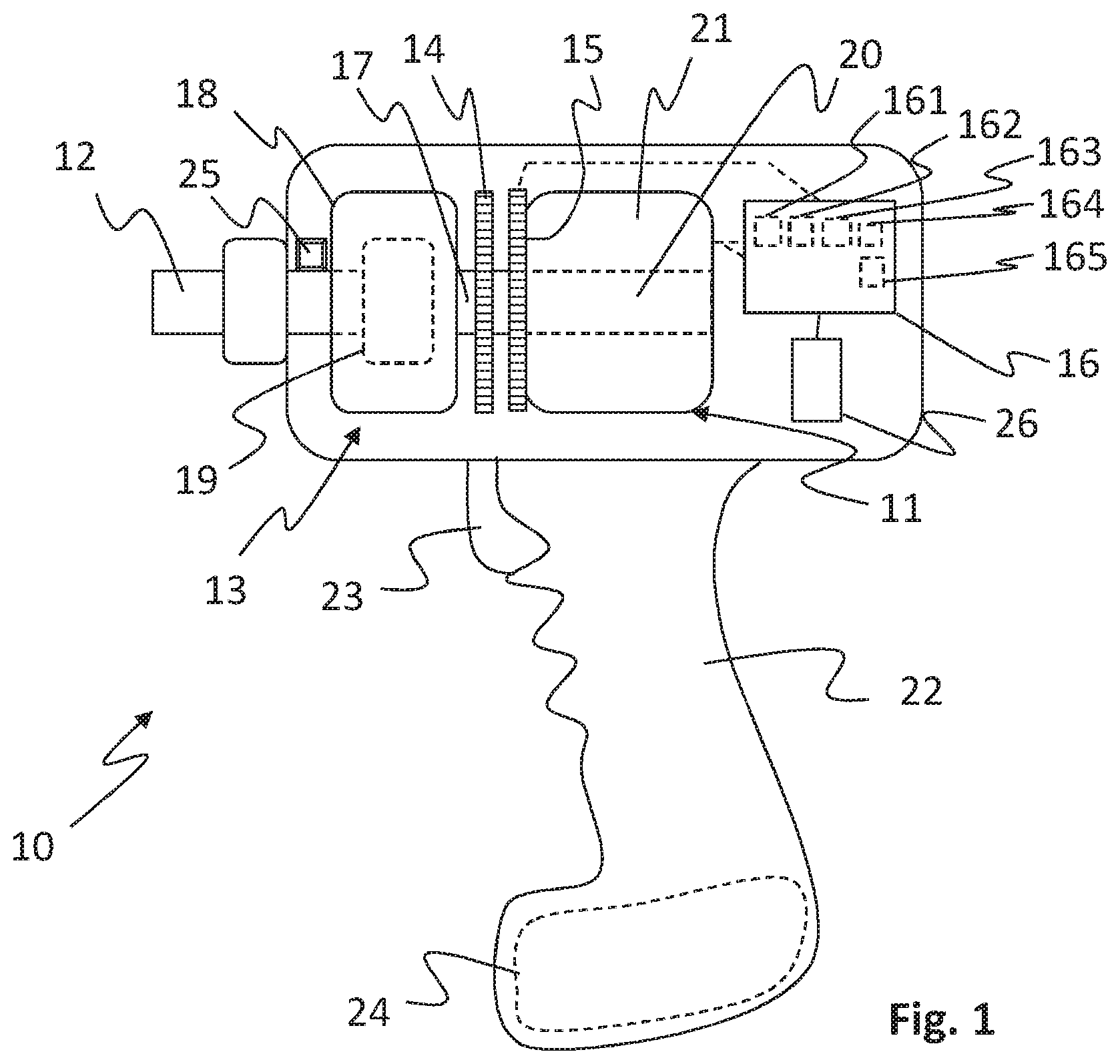
[0019] In FIG. 1 a hand held electric pulse tool 10 in accordance with a specific embodiment of the disclosure is schematically shown. The hand held electrical pulse tool 10 is configured to perform tightening operations where torque is delivered in pulses to tighten screw joints. For this purpose the hand held electrical pulse tool 10 comprises a bidirectional electric motor 11 which is arranged to deliver torque in two opposite rotational directions, i.e. clockwise and counter clockwise.
[0020] The hand held electric pulse tool 10 further comprises a handle 22, which is of a pistol type in the shown embodiment. The disclosure is however intended to cover any type of handheld pulse tools. The disclosure is not limited to handheld hand held electric pulse tools, but can also be implemented in other types of electrical pulse tools. A power supply 24, such as a battery, is arranged in the lower part of the handle and a trigger 23 is arranged for manipulation of the operator so as to power the electric motor 11. The power supply may also be a connection to an electric cable.
[0021] Further, the hand held electric pulse tool comprises an output shaft 12 and a sensor 14, 15, 25 arranged to determine a parameter value associated with the tightening of the screw joint. The sensor may be a torque sensor, an angle sensor, an accelerometer, a gyro, or the like. In the shown embodiment there is a first sensor 14, 15 that consists of an angle sensor that monitors the rotation of an input shaft 17 by means of a rotational sensor part 14 and a static sensor part 15. A second sensor 25 in the form of a torque sensor is arranged on the output shaft 12. For the disclosure either an angle sensor or a torque sensor is needed, not both. However, both sensors may be provided to offer increased accuracy or redundancy.
[0022] The shown embodiment further comprises a pulse unit 13 comprising an inertia body 18 that houses a piston activated rotator 19. The inertia body 18 is rigidly connected to the input shaft 17 and driven by a rotor 20 of the motor 11. The rotor 20 is in the shown embodiment arranged coaxially inside a stator 21 of the motor 11. A pulse is generated as cam surfaces (not shown) on the inside of the inertia body 18 interacts with the pistons so as to force the rotator 19 to rotate in a conventional manner well known in the art.
[0023] The disclosure is however not limited to pulse tools with a pulse unit. Pulses may also be produced in pulse tools with a direct connection between the motor and the output shaft by pulsing the output of the motor of the pulse tool. The disclosure also covers such pulse tools and striking pulse tools often known as impact wrenches.
[0024] For a pulse tool including a pulse unit the sensor 14, 15, 25 arranged to determine a parameter value associated with the tightening of the screw may be arranged to monitor both the rotation of the inertia body 19 and the retardation of the inertia body 19. The retardation may be used to calculate the torque that is installed into the joint. In case the sensor 14, 15, 25 arranged to determine the parameter value associated with the tightening of the screw joint is a torque sensor 25 the sensor 25 can measure the torque directly. The torque senor 25 is then arranged on the output shaft 12 as close as possible to the joint in order to monitor the delivered torque.
[0025] An object of the present disclosure is to provide an electrical pulse tool 10 that can reduce scatter in clamp force installed into the joint. This object is achieved by tightening and loosening the joint back and forth several times. By tightening and loosening the joint back and forth several times the joint will be mechanically normalized. Individual differences in surface structure will be worn down, and the population of joints will be more similar. This will result in lower difference in clamp force between different joints.
[0026] Another advantage with the inventive method according to the present disclosure is that the joint will also gain some relaxation effect due to the operation. Relaxation effect will also result in less change in clamp force over time for the joint.
[0027] Due to reaction force in the handle this method is not suitable with continuous tightening hand held tools. This since it is not feasible to manage a tightening tool where a high reaction force in the handle change directions during the tightening process.
[0028] With the hand held electric pulse tool according to the present disclosure the reaction force is negligible. Thus a change of tightening direction is possible, without ergonomic issues or other general discomforts for the operator.
[0029] Thus this object is according to an exemplary embodiment of the disclosure achieved by the hand held electric pulse tool being operative to provide several torque pulse on the output shaft in a tightening direction until a first parameter value associated with the tightening of the screw joint is reached. Then the hand held electric pulse tool being operative to pause the tightening during a first time interval. And then provide several torque pulse on said output shaft in a loosening direction until a second parameter value associated with the tightening of the screw joint is reached. Next the hand held electrical pulse tool pause the tightening during a second time interval. And then provide several torque pulse on the output shaft in a tightening direction until a third parameter value associated with the tightening of the screw joint is reached.
[0030] By the hand held electric pulse tool being operative to, it means that the hand held electric pulse tool automatically provides the tightening and loosing pulses according to the different embodiments when the trigger is actuated.
[0031] In an exemplary embodiment of the present disclosure the hand held electrical pulse tool 10 is further operative to determine required pulses in the loosening direction sufficient to condition the joint. According to another exemplary embodiment of the present disclosure the sensor is a torque sensor and the first- and second parameter values associated with the tightening of the screw joint is torque. In yet another exemplary embodiment of the present disclosure the sensor is an angle meter and the first- and second parameter values associated with the tightening of the screw joint is angle. In yet another exemplary embodiment of the present disclosure the hand held electric pulse tool is further adapted to reduce the power of the torque pulses in the loosening direction. In one exemplary embodiment the first parameter value, the second parameter value and the third parameter value can be individually specified through for instance torque, angle or number of pulses. The first time interval and the second time interval can also be individually specified. In one exemplary embodiment first time interval and the second time interval can be set to zero. The individual setting for the first parameter value, the second parameter value, the third parameter value, first time interval and the second time interval can be individually monitored and controlled.
[0032] According to one exemplary embodiment the first parameter value, the second parameter value, the third parameter value, first time interval and the second time interval can be individually monitored and controlled through torque build up and/or decrease, angle build up and/or decrease, and/or number of pulses in the tightening direction and/or loosening direction.
[0033] An advantage with the hand held electric pulse tool 10 according to the present disclosure is thus that the hand electrical pulse tool 10 can provide tightening with low variation in installed clamp force. The majority of the tightening will have the same clamp force. A quality increase is thus achieved, with respect to the clamp force installed into different joints.
[0034] Referring back to FIG. 1, the hand held electric pulse tool 10 further comprise a processor 16 arranged to control the electric motor 11. The hand held electric pulse tool 10 also comprises a memory 26 containing instructions executable by the processor 16. The processor 16 is a Central Processing Unit, CPU, microcontroller, Digital Signal Processor, DSP, or any other suitable type of processor capable of executing computer program code. The memory 26 is a Random Access Memory, RAM, a Read Only Memory, ROM, or a persistent storage, e.g. a single or combination of magnetic memory, optical memory, or solid state memory or even remotely mounted memory.
[0035] According to one aspect, the disclosure further relates to the above mentioned computer program, comprising computer readable code which, when run on the hand held electric pulse tool 10 causes the hand held electric pulse tool 10, 32 to perform any of the aspects of the disclosure described herein.
[0036] When the above-mentioned computer program code is run in the processor 16 of the hand held electric pulse tool 10 it causes the hand held electric pulse tool 10 to be operative to provide several torque pulse on the output shaft in a tightening direction until a first parameter value associated with the tightening of the screw joint is reached.
[0037] Further it causes the hand held electric pulse tool 10 to pause the tightening during a first time interval. And then provide several torque pulse on said output shaft in a loosening direction until a second parameter value associated with the tightening of the screw joint is reached. Next it causes the hand held electrical pulse tool pause the tightening during a second time interval. And then causes the hand held electric pulse tool 10 to provide several torque pulse on the output shaft in a tightening direction until a third parameter value associated with the tightening of the screw joint is reached.
[0038] According to one aspect of the disclosure the processor 16 comprises one or several of: [0039] a first providing module 161 adapted to provide several torque pulse on the output shaft in the tightening direction until the first parameter value associated with the tightening of the screw joint is reached; [0040] a pausing module 162 adapted to pause the tightening during the first time interval; [0041] a second providing module 163 adapted to provide several torque pulse on the output shaft in the loosening direction until the second parameter value associated with the tightening of the screw joint is reached; [0042] a second pausing module 164 adapted to pause the tightening during a second time interval; [0043] a third providing module 165 adapted to provide several torque pulse on the output shaft in the tightening direction until the third parameter value associated with the tightening of the screw joint is reached.
[0044] The first providing module 161, the pausing module 162, the second providing module 163, the second pausing module 164 and the third providing module 165 are implemented in hardware or in software or in a combination thereof. The modules 161, 162, 163, 164 and 165 are according to one aspect implemented as a computer program stored in the memory 26 which run on the processor 16. The hand held electric power tool 10 is further configured to implement all the aspects of the disclosure as described herein.
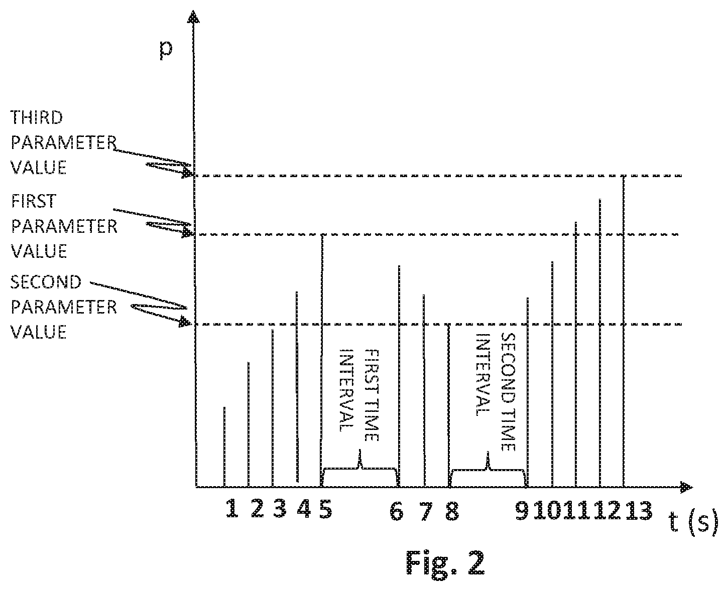
[0045] One example of a tightening performed by the hand held electric pulse tool 10 according to an exemplary embodiment is illustrated in FIG. 2. In FIG. 2 the determined parameter associated with the tightening of the screw joint is illustrated as a function of time t. In this example the tightening operation is illustrated as comprising 13 torque pulses 1-13. The tightening operation can however require fewer or more torque pulses. Each torque pulse in the tightening direction will add torque and thus increase the parameter associated with the tightening of the screw joint. And each torque pulse in the loosening direction will reduce the parameter associated with the tightening of the screw joint. As can be seen in FIG. 2 the hand held electric pulse tool 10 provides torque pulses 1 to 5 on the output shaft 12 in the tightening direction until the first parameter value associated with the tightening of the screw joint is reached. Next the hand held electric pulse tool 10 pause the tightening during the first time interval. Thereafter the hand held electric pulse tool 10 provides torque pulses 6 to 8 on the output shaft 12 in the loosening direction until the second parameter value associated with the tightening of the screw joint is reached. Next the hand held electric pulse tool 10 pause the tightening during the second time interval. Thereafter the hand held electric pulse tool 10 provides torque pulses 9 to 13 on the output shaft 12 in the tightening direction until the third parameter value associated with the tightening of the screw joint is reached.
[0046] In the tightening illustrated in FIG. 2 the hand held electric pulse tool 10 thus first provides torque pulses in the tightening direction.
[0047] Then provides torque pulses in the loosening direction. And finally again provides torque pulses in the tightening direction.
[0048] Thus the joint will be mechanically normalized. Individual differences in surface structure will be worn down, and the population of joints will be more similar. This will result in lower difference in clamp force between different joints.
[0049] There are however other exemplary embodiments of the hand held electric pulse tool 10 where the first and second time interval can be set to zero. And thus provides a tightening operation without pauses between the direction changes.
[0050] According to one exemplary embodiment of the electrical pulse tool 10 the sensor 14, 15, 25 is a torque sensor 25 and the parameter value associated with the tightening of the screw joint is torque. In this exemplary embodiment FIG. 2 illustrates torque on the y-axis.
[0051] In another exemplary embodiment of the electrical pulse tool 10 the sensor 14, 15, 25 is an angle meter and the parameter value associated with the tightening of the screw joint is angle. In this exemplary embodiment FIG. 2 illustrates angle on the y-axis.
[0052] In yet another exemplary embodiment of the electrical pulse tool 10 the hand held electric pulse tool 10 is further adapted to reduce the power of the torque pulses in the loosening direction.
[0053] As illustrated in FIG. 2, the first parameter value can be below the third parameter value. In these exemplary embodiments the hand held electric pulse tool 10 can provide tightening were the third parameter value is reached at a later stage in the tightening process.
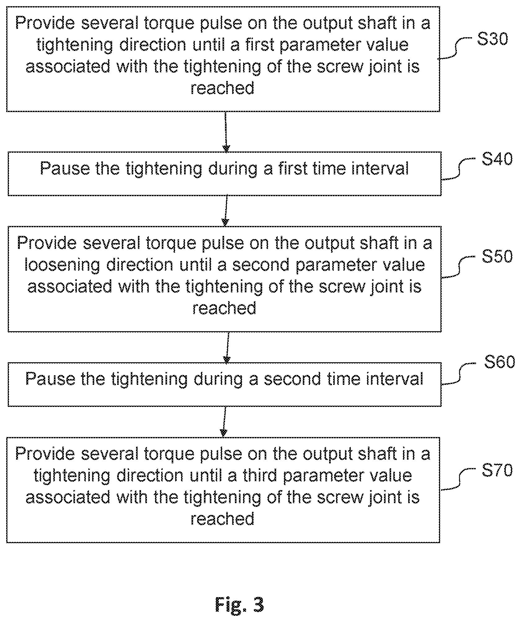
[0054] FIG. 3 illustrates the steps in a method, performed in the hand held electric pulse tool 10 for performing tightening operations according to the above described exemplary embodiments. As in the above described exemplary embodiments, torque is delivered in pulses to tighten a screw joint. Also, as above the hand held electric pulse tool 10 comprises an output shaft 12, a sensor 14, 15, 25 arranged to determine a parameter value associated with the tightening of the screw joint.
[0055] In a first step 30 the hand held electric pulse tool 10 provides torque pulses on the output shaft 12 in a tightening direction until a first parameter value associated with the tightening of the screw joint is reached. In a next step 40 the hand held electric pulse tool 10 pause the tightening during the first time interval. Thereafter in a next step 50 the hand held electric pulse tool 10 provide several torque pulse on the output shaft in a loosening direction until a second parameter value associated with the tightening of the screw joint is reached. In a next step 60 the hand held electric pulse tool 10 pause the tightening during the second time interval. Thereafter in a next step 70 the hand held electric pulse tool 10 provide several torque pulse on the output shaft in a loosening direction until a third parameter value associated with the tightening of the screw joint is reached.
[0056] According to one exemplary embodiment of the method, the method further comprises to determine required pulses in the loosening direction sufficient to condition the joint.
[0057] In another exemplary embodiment of the method, the sensor is a torque sensor and the first- and second parameter values associated with the tightening of the screw joint is torque.
[0058] According to another exemplary embodiment of the method, the sensor is an angle meter and the first- and second parameter values associated with the tightening of the screw joint is angle.
[0059] In a yet another exemplary embodiment of the method, the method further comprises reducing the power of the torque pulses in the loosening direction.
[0060] Aspects of the disclosure are described with reference to the drawings, e.g., block diagrams and/or flowcharts. It is understood that several entities in the drawings, e.g., blocks of the block diagrams, and also combinations of entities in the drawings, can be implemented by computer program instructions, which instructions can be stored in a computer-readable memory.
[0061] In the drawings and specification, there have been disclosed exemplary aspects of the disclosure. However, many variations and modifications can be made to these aspects without substantially departing from the principles of the present disclosure. Thus, the disclosure should be regarded as illustrative rather than restrictive, and not as being limited to the particular aspects discussed above. Accordingly, although specific terms are employed, they are used in a generic and descriptive sense only and not for purposes of limitation.
* * * * *
D00000
D00001
D00002
D00003
XML
uspto.report is an independent third-party trademark research tool that is not affiliated, endorsed, or sponsored by the United States Patent and Trademark Office (USPTO) or any other governmental organization. The information provided by uspto.report is based on publicly available data at the time of writing and is intended for informational purposes only.
While we strive to provide accurate and up-to-date information, we do not guarantee the accuracy, completeness, reliability, or suitability of the information displayed on this site. The use of this site is at your own risk. Any reliance you place on such information is therefore strictly at your own risk.
All official trademark data, including owner information, should be verified by visiting the official USPTO website at www.uspto.gov. This site is not intended to replace professional legal advice and should not be used as a substitute for consulting with a legal professional who is knowledgeable about trademark law.