Robot Cleaner Having Cleaning Device For Cleaning Floor Mopping Roller
Yan; Jason
U.S. patent application number 16/799975 was filed with the patent office on 2021-04-15 for robot cleaner having cleaning device for cleaning floor mopping roller. The applicant listed for this patent is Jason Yan. Invention is credited to Jason Yan.
| Application Number | 20210106197 16/799975 |
| Document ID | / |
| Family ID | 1000004707529 |
| Filed Date | 2021-04-15 |


| United States Patent Application | 20210106197 |
| Kind Code | A1 |
| Yan; Jason | April 15, 2021 |
ROBOT CLEANER HAVING CLEANING DEVICE FOR CLEANING FLOOR MOPPING ROLLER
Abstract
A robot cleaner having cleaning device for cleaning floor mopping roller is provided. The robot cleaner includes a cleaning device disposed on one side or one surface of a robot so as to divert the water stored in a water supply portion inside the robot to a cleaning body of the cleaning device. Then, the cleaning body can be used to clean a floor. When the cleaning body is used to clean the floor, a water squeezing body presses against one side of the cleaning body and a shaft body drives the cleaning body to rotate. Afterward, the water squeezing body can squeeze the water (dirty water) out of the cleaning body. Finally, a recycling body can recycle the water to a water storage portion inside the robot. In this way, the robot cleaner can clean the floor and the cleaning body at the same time.
| Inventors: | Yan; Jason; (New Taipei City, TW) | ||||||||||
| Applicant: |
|
||||||||||
|---|---|---|---|---|---|---|---|---|---|---|---|
| Family ID: | 1000004707529 | ||||||||||
| Appl. No.: | 16/799975 | ||||||||||
| Filed: | February 25, 2020 |
| Current U.S. Class: | 1/1 |
| Current CPC Class: | A47L 11/4027 20130101; A47L 11/4066 20130101; A47L 11/4088 20130101; A47L 11/4083 20130101; A47L 11/4022 20130101; A47L 2201/06 20130101; A47L 11/4041 20130101; A47L 11/292 20130101 |
| International Class: | A47L 11/292 20060101 A47L011/292; A47L 11/40 20060101 A47L011/40 |
Foreign Application Data
| Date | Code | Application Number |
|---|---|---|
| Oct 14, 2019 | TW | 108136834 |
Claims
1. A robot cleaner having cleaning device for cleaning floor mopping roller, comprising: a robot, comprising a water storage portion and a water supply portion disposed therein; a cleaning device, disposed on a side or a surface of the robot, and connected to the water supply portion, the cleaning device comprising: a connection body, connected to the side or the surface of the robot; a shaft body, encapsulated by a cleaning body and pivotally connected to the connection body; and a diversion body, comprising a diversion portion and a water output portion, the diversion portion being connected to the water supply portion to divert a water in the water supply portion to the water output portion, and the water output portion being disposed to be adjacent to the cleaning body in order to output the water to the cleaning body; a water squeezing body, disposed on the robot or the cleaning device, and one end of the water squeezing body pressing against the cleaning body to squeeze the water absorbed by the cleaning body out of the cleaning body; and a recycling body, disposed on the side or the surface of the robot, and adjacent to the water squeezing body, the recycling body being connected to the water storage portion so as to recycle the water squeezed out by the water squeezing body to the water storage portion.
2. The robot cleaner having cleaning device for cleaning floor mopping roller of claim 1, further comprising: a control element, connected to the water supply portion to control a water output volume or a water output mode of the water outputted from water supply portion to the diversion body.
3. The robot cleaner having cleaning device for cleaning floor mopping roller of claim 1, wherein the connection body comprises a concave space and the shaft body is disposed inside the concave space.
4. The robot cleaner having cleaning device for cleaning floor mopping roller of claim 1, further comprising: a removing body, disposed on the robot or the cleaning device, and pressing against the cleaning body in order to remove dirt adhering to the cleaning body.
5. The robot cleaner having cleaning device for cleaning floor mopping roller of claim 4, wherein the removing body is disposed at a position adjacent to the recycling body, such that the recycling body carrying the dirty removed by the removing body to the water storage portion.
6. The robot cleaner having cleaning device for cleaning floor mopping roller of claim 4, wherein the removing body is a brush body.
7. The robot cleaner having cleaning device for cleaning floor mopping roller of claim 1, wherein when the water storage portion is connected to the water supply portion, the robot cleaner further comprising: a filtering body, disposed between the water storage portion and the water supply portion in order to filter the water outputted from the water storage portion to the water supply portion.
8. A robot cleaner having cleaning device for cleaning floor mopping roller, comprising: a robot, comprising a water supply portion disposed therein; a cleaning device, disposed on a side or a surface of the robot, and connected to the water supply portion, the cleaning device comprising: a connection body, connected to the side or the surface of the robot; a shaft body, encapsulated by a cleaning body and pivotally connected to the connection body; a diversion body, comprising a diversion portion and a water output portion, the diversion portion being connected to the water supply portion to divert a water in the water supply portion to the water output portion, and the water output portion being disposed to be adjacent to the cleaning body in order to output the water to the cleaning body; a water squeezing body, disposed on the robot or the cleaning device, and one end of the water squeezing body pressing against the cleaning body to squeeze the water absorbed by the cleaning body out of the cleaning body; a recycling body, disposed on the side or the surface of the robot, and adjacent to the water squeezing body, the recycling body being connected to the water supply portion so as to recycle the water squeezed out by the water squeezing body to the water supply portion; and a filtering body, disposed between the recycling body and the water supply portion in order to filter the water outputted from the recycling body to the water supply portion.
9. The robot cleaner having cleaning device for cleaning floor mopping roller of claim 8, further comprising: a control element, connected to the water supply portion to control a water output volume or a water output mode of the water outputted from water supply portion to the diversion body.
10. The robot cleaner having cleaning device for cleaning floor mopping roller of claim 8, wherein the connection body comprises a concave space and the shaft body is disposed inside the concave space.
Description
BACKGROUND OF THE INVENTION
1. Field of the Invention
[0001] The present invention relates to a robot cleaner, in particular to a robot cleaner having a floor mopping roller and a cleaning device for cleaning the floor and a cleaning body at the same time.
2. Description of the Prior Art
[0002] With advance of technology, self-propelled robots are gradually becoming popular in the robot industry, and the technology thereof is also gradually becoming mature. With advance of robot technology, a robot can already provide various functions, such as production, disaster rescue, exploration, cleaning, etc. Regarding currently most-frequently used intelligent robot cleaners, many families already use robot cleaners to automatically clean the floors of their houses. Thus, robot cleaners should provide some necessary functions in order to perform the cleaning task.
[0003] When the cleaning task is performed, a robot cleaner usually sprinkles the water on the floor by a water sprinkling hole, and then mops the wetted floor by a cleaning component so as to clean the floor. However, when sprinkling the water on the floor, the robot cleaner may accidently sprinkle the water on the area not to be cleaned because the sprinkling range is too wide. Even worse, the robot cleaner may accidently sprinkle the water on the furniture or other objects.
[0004] In addition, when the robot cleaner performs the cleaning operation by the cleaning component, the robot cleaner cannot simultaneously clean the cleaning component. Thus, the cleaning component will be too dirty to effectively clean the floor after performed the cleaning operation for a period of time. Then, the user should remove the cleaning component and wash the cleaning component before the robot cleaner continues the cleaning operation again.
[0005] Therefore, it is an important issue to provide a robot cleaner capable of cleaning the floor and the cleaning body at the same time to avoid that the robot cleaner may sprinkle the water on the area not to be cleaned when sprinkling the water on the floor in order to solve the problem of prior art.
SUMMARY OF THE INVENTION
[0006] One of the primary objects of the present invention is to provide a robot cleaner having cleaning device for cleaning floor mopping roller. When the robot cleaner executes a cleaning operation, a diversion body directly diverts the water to the cleaning body in order to solve the problem that the water is sprinkled to the area not to be cleaned. Meanwhile, the robot cleaner uses a water squeezing body to clean the cleaning body and recycles the dirty water squeezed from the cleaning body by a recycling body so as to cyclically clean the cleaning body and improve the problems of prior art.
[0007] To achieve the foregoing objective, the present invention provides a robot cleaner having cleaning device for cleaning floor mopping roller. The robot cleaner includes a robot, a cleaning device, a water squeezing body and a recycling body. The robot includes a water storage portion and a water supply portion disposed therein. The cleaning device is disposed on one side or one surface of the robot, and connected to the water supply portion; the cleaning device includes a connection body, a shaft body and a diversion body. The connection body is connected to one side or one surface of the robot. The shaft body is encapsulated by a cleaning body and pivotally connected to the connection body. The diversion body includes a diversion portion and a water output portion; the diversion portion is connected to the water supply portion to divert the water in the water supply portion to the water output portion; the water output portion is disposed to be adjacent to the cleaning body in order to output the water to the cleaning body. The water squeezing body is disposed on the robot or the cleaning device, and one end of the water squeezing body presses against the cleaning body to squeeze the water absorbed by the cleaning body out of the cleaning body. The recycling body is disposed on one side or one surface of the robot, and adjacent to the water squeezing body; the recycling body is connected to the water storage portion so as to recycle the water squeezed out by the water squeezing body to the water storage portion.
[0008] Preferably, the robot cleaner having cleaning device for cleaning floor mopping roller further includes a control element. The control element is connected to the water supply portion in order to control the water output volume or the water output mode of the water outputted from water supply portion to the diversion body.
[0009] Preferably, the connection body includes a concave space and the shaft body is disposed inside the concave space.
[0010] Preferably, the robot cleaner having cleaning device for cleaning floor mopping roller further includes a removing body. The removing body is disposed on the robot or the cleaning device, and presses against the cleaning body in order to remove the dirt adhering to the cleaning body.
[0011] Preferably, the removing body is disposed at the position adjacent to the recycling body, such that the recycling body carries the dirty removed by the removing body to the water storage portion.
[0012] Preferably, the removing body is a brush body.
[0013] Preferably, when the water storage portion is connected to the water supply portion, the robot cleaner further includes a filtering body. The filtering body is disposed between the water storage portion and the water supply portion in order to filter the water outputted from the water storage portion to the water supply portion.
[0014] Another of the primary objects of the present invention is to provide a robot cleaner having cleaning device for cleaning floor mopping roller. When the robot cleaner executes a cleaning operation, a diversion body directly diverts the water to the cleaning body in order to solve the problem that the water is sprinkled to the area not to be cleaned. Meanwhile, the robot cleaner uses a water squeezing body to clean the cleaning body and recycles the dirty water squeezed from the cleaning body by a recycling body. When the dirty water is recycled to the water supply portion, the dirty water can be filtered by a filtering body so as to cyclically clean the cleaning body and use water resource, such that problems of prior art can be improved.
[0015] To achieve the foregoing objective, the present invention further provides a robot cleaner having cleaning device for cleaning floor mopping roller. The robot cleaner includes a robot, a cleaning device, a water squeezing body, a recycling body and a filtering body. The robot includes a water supply portion disposed therein. The cleaning device is disposed on a side or a surface of the robot, and connected to the water supply portion; the cleaning device includes a connection body, a shaft body and a diversion body. The connection body is connected to the side or the surface of the robot. The shaft body is encapsulated by a cleaning body and pivotally connected to the connection body. The diversion body includes a diversion portion and a water output portion; the diversion portion is connected to the water supply portion to divert the water in the water supply portion to the water output portion; the water output portion is disposed to be adjacent to the cleaning body in order to output the water to the cleaning body. The water squeezing body is disposed on the robot or the cleaning device, and one end of the water squeezing body presses against the cleaning body to squeeze the water absorbed by the cleaning body out of the cleaning body. The recycling body is disposed on the side or the surface of the robot, and adjacent to the water squeezing body; the recycling body is connected to the water supply portion so as to recycle the water squeezed out by the water squeezing body to the water supply portion. The filtering body is disposed between the recycling body and the water supply portion in order to filter the water outputted from the recycling body to the water supply portion.
[0016] Preferably, the robot cleaner further includes a control element. The control element is connected to the water supply portion to control the water output volume or the water output mode of the water outputted from water supply portion to the diversion body.
[0017] Preferably, the connection body includes a concave space and the shaft body is disposed inside the concave space.
BRIEF DESCRIPTION OF THE DRAWINGS
[0018] For a better understanding of the aforementioned embodiments of the invention as well as additional embodiments thereof, reference should be made to the Description of Embodiments below, in conjunction with the following drawings in which like reference numerals refer to corresponding parts throughout the figures.
[0019] FIG. 1 is a structural schematic view of a robot cleaner in accordance with one embodiment of the present invention.
[0020] FIG. 2 is a schematic view of the robot cleaner performing a cleaning operation in accordance with one embodiment of the present invention.
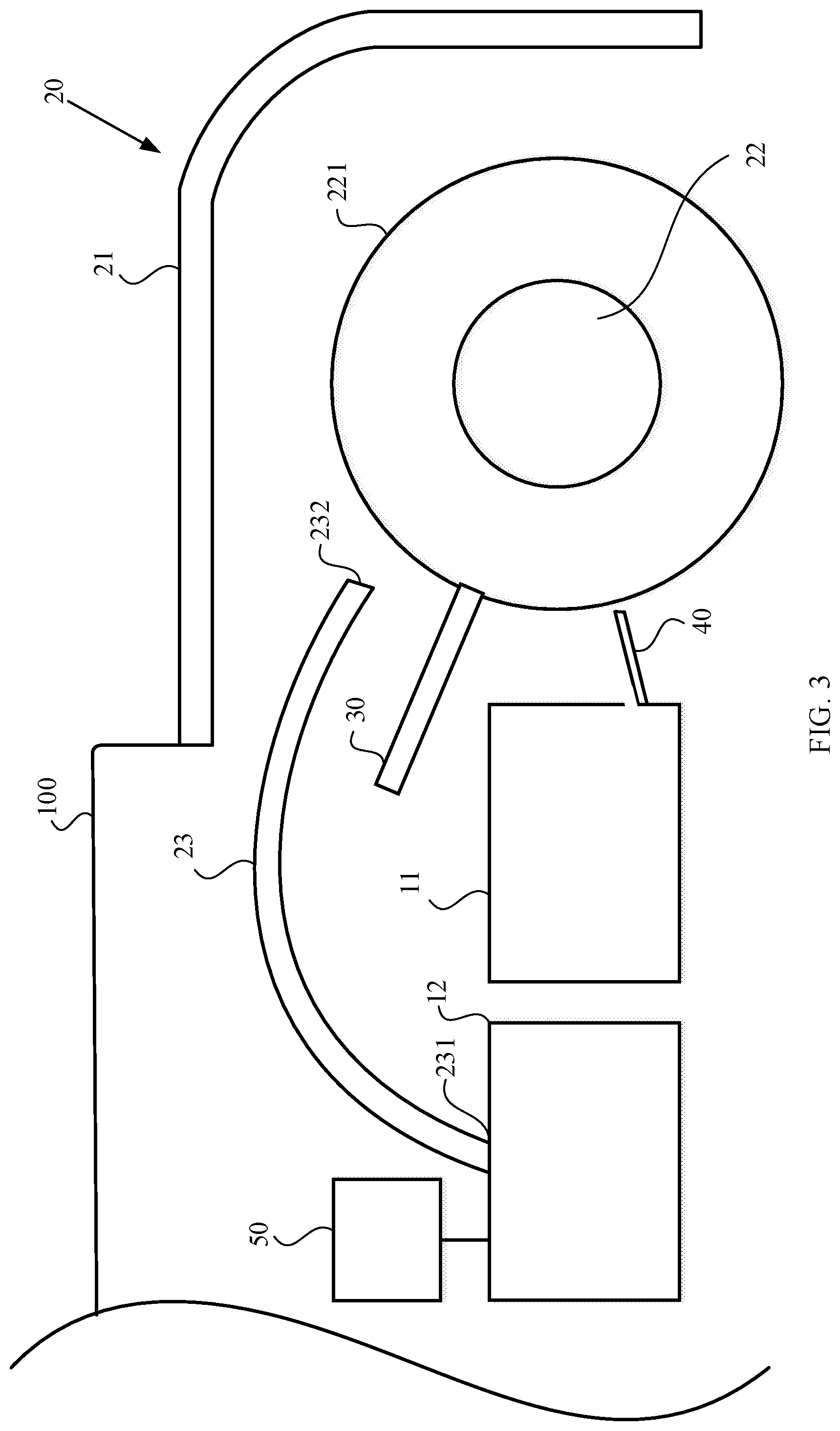
[0021] FIG. 3 is a schematic view of a control element connecting to the water supply portion in accordance with one embodiment of the present invention.
[0022] FIG. 4 is a structural schematic view of a removing body, of the robot cleaner, cleaning dirt from a cleaning body of the robot cleaner in accordance with one embodiment of the present invention.
[0023] FIG. 5 is a schematic view of a connection relation of a filtering body disposed between the water supply portion and a water storage portion in accordance with one embodiment of the present invention.
[0024] FIG. 6 is a schematic view of a connection relation of a filtering body disposed between a recycling body and the water supply portion in accordance with one embodiment of the present invention.
DETAILED DESCRIPTION OF THE PREFERRED EMBODIMENT
[0025] The following description is about embodiments of the present invention; however it is not intended to limit the scope of the present invention.
[0026] Please refer FIG. 1 and FIG. 2, which are a structural schematic view of a robot cleaner and a schematic view of the robot cleaner performing a cleaning operation in accordance with one embodiment of the present invention. As shown in FIG. 1 and FIG. 2, the present invention discloses a robot 100, a cleaning device 20, a water squeezing body 30 and a recycling body 40. The robot 100 is a household floor washing robot or floor cleaning robot. The robot 100 includes a water storage portion 11 and a water supply portion 12. The water storage portion 11 is mainly used to store the dirty water recycled and the water supply portion 12 is used to supply the water for cleaning the floor.
[0027] The cleaning device 20 is disposed on one side or one surface of the robot 100, and connected to the water supply portion 12 so as to output the water from the water supply portion 12 to the cleaning device 20. In the embodiment, the cleaning device 20 is disposed on one side of the robot 100 for illustration.
[0028] The cleaning device 20 includes a connection body 21, a shaft body 22 and a diversion body 23. The connection body 21 is connected to the bottom surface of the robot 100 and protrudes from the periphery of the robot 100. More specifically, the connection body 21 may be a housing having a concave space 211.
[0029] The shaft body 22 is pivotally connected to the connection body 21 and disposed inside the concave space 211, such that the shaft body 22 can rotate clockwise or counterclockwise in the concave space 211. In addition, the shaft body 22 is further encapsulated by a cleaning body 221. When the shaft body 22 rotates, the cleaning body 221 is driven by the shaft body 22 to rotate in the direction which the shaft body 22 rotates. However, as the cleaning body 221 is used to absorb the water provided by the water supply portion 12 so as to clean dirt or dust on a floor, the cleaning body 221 should be an object with proper water absorption ability (e.g. cloth).
[0030] The diversion body 23 may be a tube, which has a diversion portion 231 and a water output portion 232. The diversion portion 231 is connected to the water supply portion 12 so as to divert the water inside the water supply portion 12 to the water output portion 232. The water output portion 232 is disposed at the position adjacent to the cleaning body 221 in order to divert the water to the cleaning body 221. More specifically, the mean of the water supply portion 12 drawing out the water and diverting the water to the diversion body 23 can be realized by height difference. In other words, the water supply portion 12 is disposed at the position higher than that of the cleaning device 12. Then, the water can be controlled by a valve body or a water pump; the valve body can be used to control whether the water is diverted to the diversion body 23; the water pump can be used to draw out the water to the diversion body 23. In the embodiment, the water is controlled by a water pump to draw out the water to the diversion body 23. However, the means of the water supply portion 12 drawing out the water are already known by those skilled in the art, so will not be described again in the following content.
[0031] The water squeezing body 30 may be a plate body with proper hardness, and disposed on the robot 100 or the cleaning device 20. Therefore, when one end of the water squeezing body 30 presses against one side of the cleaning body 221 and the cleaning body 221 is rotating, the water squeezing body 30 does not break because the hardness of the water squeezing body 30 can effectively resist the kinetic energy of the cleaning body 221, and can simultaneously squeeze the water absorbed by the cleaning body 221 out of the cleaning body 221.
[0032] The recycling body 40 is disposed on one side or one surface of the robot 100, and disposed at the position adjacent to the water squeezing body 30. The recycling body 40 is connected to the water storage portion 11 in order to recycle the water squeezed out by the water squeezing body 30 to the water storage portion 11.
[0033] Via the above structure, when the robot cleaner performs a cleaning operation, the cleaning body 221 contacts the floor. Then, when the robot cleaner moves forward, the friction between the cleaning body 221 and the floor is applied to the cleaning body 221. Besides, as the shaft body 22 is pivotally connected to the connection body 21, the cleaning body 221 rotates in the direction opposite to the moving direction of the robot cleaner (i.e. the cleaning body 221 rotates counterclockwise). When a part of the cleaning body 221 rotates to the position corresponding to the water output portion 232, the water output portion 232 diverts the water from the water supply portion 12 to the part of the cleaning body 221 to wet the part of the cleaning body 221. Then, when rotating to contact the floor, the part of the cleaning body 221 can effectively clean the floor. When the part of the cleaning body 221 rotates to the position where the water squeezing body 30 presses, the water squeezing body 30 can squeeze the water (dirty water) absorbed by the cleaning body 221 out of the cleaning body 221. Next, the recycling body 40 recycles the water squeezed from the cleaning body 221 to the water storage portion 11. Afterward, when the part of the cleaning body 221 rotates to the position corresponding to the water output portion 232, the water output portion 232 diverts the water to the part of the cleaning body 221 again and repeat the above process.
[0034] Therefore, via the design of the diversion body 231 and the water squeezing body 30, the cleaning body 221 can be cyclically cleaned and simultaneously clean the floor, which can solve the problem that the currently available robot cleaner cannot be used again until the user detaches and clean the cleaning component.
[0035] Please refer to FIG. 3, which is a schematic view of a control element connecting to the water supply portion in accordance with one embodiment of the present invention. As shown in FIG. 3, as the floors of different buildings may be made of different materials, it is necessary to use the cleaning body 221 with different water content to clean the floors of different materials in order to effectively remove dirt and dust from the floors. Besides, it is also necessary to avoid that the cleaning body 221 is too wet or too dry after the water supply portion 12 supplies the water to the cleaning body 221 for a period of time.
[0036] Moreover, the robot cleaner further includes a control element 50 connected to the water supply portion 12. The control element 50 is used to control the water output volume or the water output mode of the water outputted from the water supply portion 12. Therefore, when the floor is, for example, made of wood, the control element 50 can reduce the water output volume outputted from the water supply portion 12 in order to avoid that the water infiltrates into the floor because the cleaning body 221 absorbs too much water. On the contrary, when the floor is, for example, made of marble, the control element 50 can increase the water output volume outputted from the water supply portion 12 so as to avoid that the cleaning body 221 cannot effectively clean the marble floor because the cleaning body 221 fails to absorb enough water. In this way, the robot cleaner can effectively clean the floor.
[0037] The control element 50 can also control the water output mode of the water supply portion 12 to control the water content of the cleaning body 21 with a view to make the cleaning body 21 have proper water content. For example, the water supply portion 12 can supply the water to the cleaning body 221 according to a dynamic water output mode or a time-based water output mode. For example, when the control element 50 controls the water supply portion 12 to supply the water to the cleaning body 221 according to the dynamic water output mode, the water supply portion 12 can output the water for about 0.1.about.1 second and stop outputting the water for about 0.1.about.1 second to regularly or irregularly supply the water to the cleaning body 221. Alternatively, when the control element 50 controls the water supply portion 12 to supply the water to the cleaning body 221 according to the time-based water output mode, the water supply portion 12 can output the water for about 1.about.5 minutes and stop outputting the water for about 10.about.30 seconds to regularly or irregularly supply the water to the cleaning body 221.
[0038] As described above, the control element 50 can control the water output volume or the water output mode of the water supply portion 12 so as to effectively control the water content of the cleaning body 221, such that the robot cleaner can effectively clean the floors made of different materials.
[0039] The time settings described in the embodiment are just to illustrate the difference between the dynamic water output mode and the time-based water output mode instead of limiting the scope of the claims of the present invention.
[0040] Those skilled in the art can realize the dynamic water output mode and the time-based water output mode by other time settings by referring to the embodiment.
[0041] Please refer to FIG. 4, which is a structural schematic view of a removing body, of the robot cleaner, cleaning dirt from a cleaning body of the robot cleaner in accordance with one embodiment of the present invention. As shown in FIG. 4, when the cleaning body 221 cleans the floor, some dirt (e.g. hairs or flocks, etc.) may be attached to the cleaning body 221 when the cleaning body 221 is rotating.
[0042] Therefore, the robot cleaner further includes a removing body 60 so as to effectively clean the cleaning body 221 and remove the dirt from the cleaning body 221; the removing body 60 may be, for instance, a brush body. The removing body 60 is disposed on the robot 100 or the cleaning device 20, and disposed at the position adjacent to the recycling body 40. The removing body 60 presses against the cleaning body 221 (more specifically, the bristles of the removing body 60 presses against the cleaning body 221). Thus, when the cleaning body 221 rotates, the removing body 60 can remove the dirt attached to the cleaning body 221. The dirt removed by the removing body 60 can be returned to the recycling body 40 in order to store the dirt in the water storage portion 11.
[0043] Please refer to FIG. 5 and FIG. 6; FIG. 5 is a schematic view of a connection relation of a filtering body disposed between the water supply portion and a water storage portion in accordance with one embodiment of the present invention; FIG. 6 is a schematic view of a connection relation of a filtering body disposed between a recycling body and the water supply portion in accordance with one embodiment of the present invention. As shown in FIG. 5, the robot cleaner further includes a filtering body 70 in order to effectively and repeatedly recycle water resource so as to the time of replacing water; the filtering body 70 may be disposed between the water storage portion 11 and the water supply portion 12. Alternatively, as shown in FIG. 6, when the robot cleaner fails to have the water storage portion 11, the filtering body 70 is disposed between the recycling body 40 and the water supply portion 12 in order to filter the dirty water received from the recycling body 40 and then supply the water to the cleaning body 221 via the water supply portion 12, which can reduce the waste of water resource.
[0044] In the above description of the present invention, it should be understood that the terms "clockwise", "counterclockwise", "central", "transverse", "up", "down", "left", "right", "top", "bottom", "inner", "outer" and other terms describing direction or position relations are only used to indicate the directions and the positions shown in the drawings. These terms are only used to conveniently describe the present invention and simplify the content of the specification instead of indicating or implying that the devices or the elements described in the specification should be at specific positions, in specific directions or operated in specific ways. Therefore, the above terms should not be understood to limit the scope of the claims of the present invention.
[0045] The above disclosure is related to the detailed technical contents and inventive features thereof. Those skilled in the art may proceed with a variety of modifications and replacements based on the disclosures and suggestions of the invention as described without departing from the characteristics thereof. Nevertheless, although such modifications and replacements are not fully disclosed in the above descriptions, they have substantially been covered in the following claims as appended.
* * * * *
D00000
D00001
D00002
D00003
D00004
D00005
D00006
XML
uspto.report is an independent third-party trademark research tool that is not affiliated, endorsed, or sponsored by the United States Patent and Trademark Office (USPTO) or any other governmental organization. The information provided by uspto.report is based on publicly available data at the time of writing and is intended for informational purposes only.
While we strive to provide accurate and up-to-date information, we do not guarantee the accuracy, completeness, reliability, or suitability of the information displayed on this site. The use of this site is at your own risk. Any reliance you place on such information is therefore strictly at your own risk.
All official trademark data, including owner information, should be verified by visiting the official USPTO website at www.uspto.gov. This site is not intended to replace professional legal advice and should not be used as a substitute for consulting with a legal professional who is knowledgeable about trademark law.