Impact Mitigation Fit Pods
GLOVER; Travis E. ; et al.
U.S. patent application number 17/113407 was filed with the patent office on 2021-04-15 for impact mitigation fit pods. The applicant listed for this patent is VPG AcquisitionCo, LLC. Invention is credited to Kurt FISCHER, Kayla FUKUDA, Travis E. GLOVER, Adam KOLLGAARD, Jason NEUBAUER, Marie PAHLMEYER, Andre H.P. STONE.
| Application Number | 20210106091 17/113407 |
| Document ID | / |
| Family ID | 1000005325111 |
| Filed Date | 2021-04-15 |


View All Diagrams
| United States Patent Application | 20210106091 |
| Kind Code | A1 |
| GLOVER; Travis E. ; et al. | April 15, 2021 |
Impact Mitigation Fit Pods
Abstract
The protective helmet, the fit pod assemblies and the respective components relates to methods, devices, and systems for improved helmet systems to enhance athletic performance by dispersing impact forces and/or improving helmet comfort and/or fit through size customization and/or conforming to contours of a wearer's head. If desired, the various fit pod assemblies can include modular features to provide a semi-custom and/or customized feel for plug and play assembly and/or retrofitting a commercially available helmet and/or other item of protective clothing.
| Inventors: | GLOVER; Travis E.; (Seattle, WA) ; PAHLMEYER; Marie; (Seattle, WA) ; KOLLGAARD; Adam; (Seattle, WA) ; FUKUDA; Kayla; (Seattle, WA) ; NEUBAUER; Jason; (Sammamish, WA) ; STONE; Andre H.P.; (Seattle, WA) ; FISCHER; Kurt; (Edmonds, WA) | ||||||||||
| Applicant: |
|
||||||||||
|---|---|---|---|---|---|---|---|---|---|---|---|
| Family ID: | 1000005325111 | ||||||||||
| Appl. No.: | 17/113407 | ||||||||||
| Filed: | December 7, 2020 |
Related U.S. Patent Documents
| Application Number | Filing Date | Patent Number | ||
|---|---|---|---|---|
| PCT/US2019/036092 | Jun 7, 2019 | |||
| 17113407 | ||||
| 62810211 | Feb 25, 2019 | |||
| 62748309 | Oct 19, 2018 | |||
| 62682102 | Jun 7, 2018 | |||
| Current U.S. Class: | 1/1 |
| Current CPC Class: | A42B 3/127 20130101; A42B 3/064 20130101 |
| International Class: | A42B 3/06 20060101 A42B003/06; A42B 3/12 20060101 A42B003/12 |
Claims
1. An impact mitigation pod assembly comprising: a fit pod, the fit pod comprises a top layer, a bottom layer, and at least one foam layer; the at least one foam layer disposed between the top layer and the bottom layer; and a connection mechanism, the connection mechanism having a first portion and a second portion, the first portion of the connection mechanism being disposed between the top layer and the bottom layer, the second portion comprising a shape and extending perpendicularly away from the fit pod.
2. The impact mitigation pod assembly of claim 1, wherein the top layer comprises a plurality of channels, the plurality of channels extending in one or more orientations.
3. The impact mitigation pod assembly of claim 1, wherein the first portion having a planar configuration.
4. The impact mitigation pod assembly of claim 3, wherein the bottom layer comprises at least one opening, the at least one opening sized and configured to receive the second portion of the connection mechanism.
5. The impact mitigation pod assembly of claim 1, wherein the shape of the second portion is triangular.
6. The impact mitigation pod assembly of claim 1, wherein the top layer and bottom layer are different materials or the same materials.
7. The impact mitigation pod assembly of claim 1, wherein the at least one foam layer comprises a first foam layer and a second foam layer.
8. The impact mitigation pod assembly of claim 1, wherein the bottom layer comprises polycarbonate.
9. The impact mitigation pod assembly of claim 1, wherein the fit pod further comprises a flat, planar configuration.
10. The impact mitigation pod assembly of claim 1, wherein the fit pod further comprises a curved configuration.
11. The impact mitigation pod assembly of claim 7, wherein the first foam layer comprises a comfort foam and the second foam layer comprises an impact foam.
12. A protective helmet system comprising: a helmet, the helmet comprising an inner surface, the inner surface including a plurality of connection mechanism openings, the plurality of connection mechanism openings positioned in different regions of the inner surface, the plurality of connection mechanism openings having a shape; and a plurality fit pod assemblies, the plurality of fit pod assemblies comprises a fit pod and a connection mechanism, the connection mechanism having a first portion and a second portion, the first portion of the connection mechanism being disposed within the plurality of fit pod assemblies, the second portion comprising a shape and extending perpendicularly away from the plurality of fit pod assemblies; the shape of the second portion substantially matching the shape of the plurality of connection mechanism openings of the inner surface. the second portion of the connection mechanism of the plurality of fit pod assemblies inserted into the plurality of connection mechanism openings and removably coupled to the inner surface.
13. An impact mitigation pod assembly comprising: a fit pod, the fit pod comprises a top layer, a bottom layer, and at least one foam layer; the at least one foam layer disposed between the top layer and the bottom layer, the top layer comprises a plurality of channels, the plurality of channels extending in one or more orientations; and a connection mechanism, the connection mechanism having a first portion and a second portion, the first portion of the connection mechanism being disposed between the top layer and the bottom layer, the second portion comprising a shape and extending perpendicularly away from the fit pod.
14. The impact mitigation pod assembly of claim 13, wherein the first portion having a planar configuration.
15. The impact mitigation pod assembly of claim 13, wherein the bottom layer comprises at least one opening, the at least one opening sized and configured to receive the second portion of the connection mechanism.
16. The impact mitigation pod assembly of claim 13, wherein the shape of the second portion is triangular.
17. The impact mitigation pod assembly of claim 13, wherein the top layer and bottom layer are different materials or the same materials.
18. The impact mitigation pod assembly of claim 13, wherein the at least one foam layer comprises a first foam layer and a second foam layer.
19. The protective helmet of claim 13, wherein the plurality of channels further comprises a channel width, the channel width being movable between first position that allows the channel width to be in a neutral position making the fit pod planar prior to removably coupling to the helmet, and a second position that decreases the channel width making the fit pod curved.
20. The impact mitigation pod assembly of claim 18, wherein the first foam layer comprises a comfort foam and the second foam layer comprises an impact foam.
Description
CROSS-REFERENCE TO RELATED APPLICATIONS
[0001] This application is a continuation of Patent Cooperation Treaty Application Serial No. PCT/US2019/036092, entitled "Impact Mitigation Fit Pods," filed Jun. 7, 2019 which claims benefit of U.S. Provisional Patent Appl. Ser. No. 62/682,102 entitled "Impact Mitigation Pods," filed Jun. 7, 2018, U.S. Provisional Patent Appl. Ser. No. 62/748,309 entitled "Impact Mitigation Pods," filed Oct. 19, 2018 and U.S. Provisional Patent Appl. Ser. No. 62/810,211 entitled "Impact Mitigation Pods," filed Feb. 25, 2019, which all the disclosures are incorporated by reference herein in its entireties.
TECHNICAL FIELD
[0002] The present invention relates to methods, devices, and systems for improved helmet systems with fit pods and/or improved comfort liners to enhance athletic performance by reducing acceleration, dispersing impact forces and/or improving helmet comfort and/or fit. If desired, the various improved helmet comfort liner components can include modular components as well as semi-custom and/or customized components for plug and play assembly and/or retrofitting a commercially available helmet and/or other item of protective clothing.
BACKGROUND OF THE INVENTION
[0003] Helmets and other protective apparel typically incorporate impact absorbing structures to desirably prevent and/or reduce the effect of collisions between the wearer and other stationary and/or moving objects. For example, an athletic helmet typically protects a skull and various other anatomical regions of the wearer from collisions with the ground, equipment, other players and/or other stationary and/or moving objects, while body pads and/or other protective clothing seeks to protect other anatomical regions. Helmets are typically designed with the primary goal of preventing traumatic skull fractures and other blunt trauma, while body pads and ballistic armors are primarily designed to cushion blows to other anatomical regions and/or prevent/resist body penetration by high velocity objects such as bullets and/or shell fragments.
[0004] However, the proper functioning of a helmet, its impact structures and/or comfort liners is often highly dependent upon the proper sizing and "fit" of the headgear to the wearer's head. A helmet that does not fit and/or is uncomfortable to wear is often not worn, resulting in the absence of the helmet when it is needed for protection. Current helmet manufacturers often provide sub-optimal methods for sizing and/or fitting of a helmet because current fitting/sizing methods are generally ineffective in accommodating the unique shape and size of every wearer's head, resulting in an inaccurate sizing and/or shaping of the helmet and/or impact structures for the wearer. Inaccurate sizing or shaping of the helmet supports can allow undesirable movement between the wearer's head and the helmet structures, as well as increased pressure of the helmet on regions of the wearer's head (i.e., "hot spots"), and such helmets may not effectively protect the wearer's head from trauma and the effects of intense physical contact and may perform improperly to absorb and/or significantly ameliorate impacts. For example, a helmet that is too large for a wearer's head can allow the user's head to move within the helmet, allowing the user's head to contact sides of the helmet in an undesirable manner during impact. Another major consideration in protective headgear is wearer comfort--if the helmet is uncomfortable or painful to wear, this discomfort may distract the user's attention (potentially leading to more severe impacts) and/or may cause the user to remove or displace the helmet prior to the moment of impact. In a similar manner, a helmet that is too small for the wearer's head may be uncomfortable or painful for the wearer to wear.
[0005] Furthermore, the use of outdated impact mitigation technologies and/or comfort liners may, in certain instances, greatly reduce the effectiveness of the helmet system and potentially lead to increased incidence and/or severity of injuries. Many conventional football helmets are manufactured with inflatable comfort liners that may be sometimes combined with soft foam comfort liners and/or other materials in an effort to help attenuate impact forces incident to the helmet. These inflatable liners can have a plurality of separate inflatable cells, with these cells adjacently arranged into a general shape inside the helmet, often with interconnect air passageways and the inflatable cells often include a separate valve-controlled inflation tube that may extend out the back or side of the helmet. To "fit" the helmet, the wearer or an assistant (often referred to as the "sizer") may increase or decrease the pressure of air or other fluid/gas within the inflatable comfort liner to desirably increase and/or decrease the size of the cells, while seeking to improve the wearer's fit, comfort and protection. Unfortunately, inflatable liners and related technology often function sub-optimally, in that the inflatable cells are prone to leakage, damage and are highly sensitive to environmental temperatures (i.e., they commonly increase or decrease in size due to temperature fluctuations and/or air pressure changes). Inflatable cells also require more frequent of adjustment (or "spot checks") in comparison to foams and/or other materials to maintain proper sizing in-between pressurization and/or depressurization cycles. In addition, inflatable cells often suffer from a lack of uniform inflation, where some portions of the inflatable comfort liner may be over-inflated and other portions under-inflated; and the distribution of inflatable cells may not be uniform and/or may cause a tilting effect (i.e., inflatable jaw pads or side pads) or a "lift effect" (with an inflatable crown pad) on the helmet. Such negative characteristics of the inflatable comfort liners can adversely affect the fit of the helmet and reduce or eliminate any protection the helmet presumes to provide.
[0006] In addition, research has been revealing that traumatic brain injuries (TBI's) are not only caused by linear impacts, but impacts resulting from oblique, tangential and/or rotational acceleration because the brain is sensitive to rotational motion. Rotational motion and/or acceleration may cause TBI's that results from interrupting the speed of the body relative to the head, which the unrestricted movement of the head occurs out of synchrony with the movement of the neck, torso, and/or lower limbs of the body. Injuries received by players, such as concussions, subdural hemorrhage, hematomas and diffuse axonal injury, can be more easily caused by rotational head motion. Unfortunately, current helmet designs to not adequately protect the head from TBI's due to oblique, tangential and/or rotational acceleration.
BRIEF SUMMARY OF THE INVENTION
[0007] Therefore, there is a need for an improved protective helmet system and methods for sizing and fitting helmets and other protective apparel for a wearer. Improved methods of sizing and shaping a helmet may desirably take into account the shape, size and/or anatomical variability of the wearer's skull. Furthermore, an improved helmet system may include a modular fit pod system to improve and/or enhance helmet shape, size, comfort, fit and/or attenuation in response to high intensity and/or repetitive impact events. This is achieved by providing a different sizes and thicknesses of each fit pod assembly and iterating to acquire the best fit and impact protection.
[0008] In one exemplary embodiment, the modular fit pod system may comprise one or more fit pod assemblies. The fit pod assemblies comprise a fit pod and a connection mechanism, the fit pod comprises a top layer, a bottom layer, a first foam layer and a second foam layer; the first foam layer and the second foam layer disposed between the top layer and bottom layer, the top layer having top surface and a bottom surface, the top layer top surface having a plurality of channels that extend from the top surface towards the bottom surface, the bottom layer having at least one opening, the at least one opening sized and configured to receive a portion of a second portion of the connection mechanism, the top layer coupled to bottom layer; and the connection mechanism having a first portion and the second portion, the first portion having a planar configuration, the second portion extending perpendicularly away from the first portion, the second portion sized and configured to be positioned within the at least one opening. The fit pod assemblies may comprise a flat, planar configuration and/or a curved configuration. The top layer and/or bottom layer may comprise the same materials or different materials. The first foam layer and the second foam layer may comprise the same foam materials or different foam materials.
[0009] In another exemplary embodiment, the modular fit pod system may comprise an alternate one or more fit pod assemblies. The alternate one or more fit pod assemblies comprise a fit pod and a connection mechanism, the fit pod having top surface and a bottom surface, the fit pod top surface having a plurality of channels that extend from the top surface towards the bottom surface. The connection mechanism having a first portion and the second portion, the first portion being larger than the second portion, the second portion extending perpendicularly away from the first portion, the connection mechanism being coupled to the fit pod. More specifically, the connection mechanism first portion is coupled to the fit pod bottom surface. The fit pod may comprise a foam material. The fit pod assemblies may comprise a flat, planar configuration and/or a curved configuration.
[0010] In another exemplary embodiment, the modular fit pod system may comprise an alternate one or more fit pod assemblies. The alternate one or more fit pod assemblies comprise a fit pod, a connection mechanism, and an elastomeric support system. The fit pod having top surface and a bottom surface, the fit pod top surface having a plurality of channels that extend from the top surface towards the bottom surface. The fit pod assemblies may comprise a flat, planar configuration and/or a curved configuration. The one or more fit pods further comprise one or more foam layers that are disposed within the fit pod. The elastomeric support system may comprise an elastomeric polymer frame, a woven elastomeric fabric or cover, an elastomeric fabric or cover (such as a 2-way or 4-way stretch fabric), and/or one or more springs. The elastomeric support system may further comprise a low friction material or layer, the low friction material or layer coupled the fit pod bottom surface. The low friction material or layer to allow the connection mechanism to be slidably movable from a first position, the first position being the connection mechanism is positioned in a neutral position, to a second position, which the connection mechanism is positioned laterally from the neutral position after an oblique or tangential impact force. The elastomeric support system may be coupled to the one or more fit pods. The connection mechanism having a first portion and the second portion, the first portion being larger than the second portion, the second portion extending perpendicularly away from the first portion, the connection mechanism being coupled to the fit pod. More specifically, the connection mechanism first portion is coupled to the fit pod bottom surface and/or coupled to the low-friction material or layer. The fit pod may comprise a foam material.
[0011] In one exemplary embodiment, an improved protective helmet system may comprise a helmet and one or more modular fit pods and/or fit pod layer(s). The helmet may include an outer layer. The helmet may further comprise an inner layer and an impact mitigation structure and/or layer, the impact mitigation layer and/or structure disposed between the inner and outer layer, and/or any combination thereof. The fit pod assemblies are disposed within the helmet and may be desirably positioned around various locations or regions around the wearer's head, such as covering much of the area between an inner shell of the helmet and the user's head. The fit pod layer comprises a plurality of fit pod assemblies. The plurality of fit pod assemblies may comprise a flat, planar configuration and/or a curved configuration. Such plurality of fit pod assemblies may include one or more of the following: a frontal assembly (or front), a crown assembly, an occipital assembly (or lower-back), a mid-back assembly, a parietal assembly (or midline), and a temporal assembly (right and/or left sides), and/or any combination(s) thereof. At least a portion of the fit pod assemblies may be removably coupled to the helmet, including at least one inner layer, impact mitigation layer, outer layer and/or any combination thereof to facilitate energy absorption, reduce angular motion of the wearer after impact, enhance fit and comfort.
[0012] In one exemplary embodiment, the improved protective helmet system may comprise a helmet, one or more fit pod assemblies and/or a fit pod layer, and a comfort liner. The helmet having at least one outer layer, an optional inner layer and an impact mitigation layer disposed between the inner and outer layer, and/or any combination thereof. The fit pod layer comprises a plurality of fit pod assemblies. The fit pod layer may include impact mitigation structure or material, comfort foam and may be desirably positioned around various locations of the wearer's head, such as covering some of the area between an inner shell of the helmet and the user's head. The fit pod assemblies may also include a connection mechanism to connect or attach the pods to the inner shell, the impact mitigation layer, the outer shell or any other parts of the helmet system. Such plurality of fit pod assemblies may include one or more of the following: a frontal assembly (or front), a crown assembly, an occipital assembly (or lower-back), a mid-back assembly, a parietal assembly (or midline), and a temporal assembly (right and/or left sides), and/or any combination(s) thereof. At least a portion of the fit pod assemblies may be removably coupled to at least one inner layer, impact mitigation layer, outer layer, comfort liner and/or any combination thereof to facilitate energy absorption, reduce angular motion of the wearer after impact, enhance fit and comfort. The comfort liner may comprise a first layer, a second layer, and a foam layer. The foam layer may include a plurality of segmented foam pads, each of the plurality of segmented foam pads optionally being separated by gap. The foam layer can be disposed between the first and second layer, or the foam layer could be laminated with first and/or second layers. The gap has a thickness, the thickness allowing substantial flexibility and/or a pivotal connection.
[0013] In one exemplary embodiment, an improved helmet system may comprise a helmet and one or more fit pod assemblies or fit pod layers. The one or more fit pod layers may comprise at least one bottom layer, at least one top layer, at least one foam layer, a connection mechanism, and/or any combination thereof. The at least one bottom layer or least one top layer may comprise a plastic material, a foam material or foam layer, a resilient fabric that may be a two-way or four-way stretch material and/or any elastic material, and/or any combination thereof. In one embodiment, the top layer and/or bottom layer may comprise a 2-way or 4 way stretch fabric and a polymer film. The polymer films comprise a polyethylene film, polypropylene film, a polyurethane film, a nylon film, a polyester film, a polyvinyl chloride film and/or any combination thereof. The polymer film may be coupled or laminated to the 2-way or 4-way stretch fabric. The at least one top layer and at least one bottom layer may be the same material, or they may be different materials. The at least one foam layer may a one single layer, and/or it may be a plurality of foam layers (two or more). In addition, the pocketed fit pod assemblies may further comprise an impact mitigation layer.
[0014] In one exemplary embodiment, an improved helmet system may comprise a helmet and one or more modular fit pods and/or fit pod layer(s) to help protect against oblique, tangential and/or rotational acceleration. The helmet may include an outer layer. The helmet may further comprise an inner layer and/or an impact mitigation layer disposed on an inner surface of the outer layer, and/or between the outer layer or inner layer, and/or any combination thereof. The fit pod layer may comprise a one or more modular fit pod assemblies. The one or more modular fit pod assemblies may be desirably positioned around various locations of the wearer's head, such as covering much of the area between an inner shell of the helmet and the user's head. Each of the fit pod assemblies may also include a fit pod, a connection mechanism and an elastomeric support mechanism. The each one or more fit pods may comprise a top layer, one or more foam layers, and a bottom layer. The elastomeric support mechanism may comprise an elastomeric polymer frame, a woven elastomeric fabric or cover, an elastomeric fabric or cover (such as a 2-way or 4-way stretch fabric), and/or one or more springs. The elastomeric support mechanism may further comprise a low friction material to allow the connection mechanism to be slidably movable from a first position, which the connection mechanism is positioned in a neutral position, to a second position, which the connection mechanism is positioned laterally from the neutral position after a tangential and/or oblique impact force. The elastomeric support system may be coupled to the each one or more fit pods. Such plurality of fit pod assemblies may include one or more of the following: a frontal assembly (or front), a crown assembly, an occipital assembly (or lower-back), a mid-back assembly, a parietal assembly (or midline), and a temporal assembly (right and/or left sides), and/or any combination(s) thereof. At least a portion of the fit pod assemblies may be removably coupled to at least one inner layer, impact mitigation layer, outer layer and/or any combination thereof to facilitate energy absorption, reduce angular motion and/or rotational motion of the wearer after impact, enhance fit and comfort.
[0015] In one exemplary embodiment, the improved helmet system may comprise a helmet, one or more modular jaw pod system. The jaw fit pod system can comprise a jaw fit pod assembly and a bridge fit pod assembly. The jaw pod assembly comprises a jaw connection plate, a face frame or base, and at least one jaw fit pod. The face frame have a first surface and a second surface, the first or second surface has a cavity, the cavity is shaped and configured to receive the jaw connection plate, the jaw connection plate shaped and configured to fit within the cavity, the at least one jaw fit pod and/or jaw fit pod assembly having at least one foam layer., the jaw fit pod and/or jaw fit pod assembly coupled to the first or second surface of the face frame. The bridge fit pod assembly comprises a bridge connection plate, a bridge frame or base, and a bridge fit pod. The bridge frame have a first surface and a second surface, the first or second surface has a cavity, the cavity is shaped and configured to receive the bridge connection plate, the bridge connection plate shaped and configured to fit within the cavity, the bridge fit pod and/or bridge fit pod assembly having at least one foam layer, the bridge fit pod and/or jaw fit pod assembly coupled to the first or second surface of the bridge frame. The bridge fit pod and/or the bridge fit pod assembly being removably coupled to the helmet.
BRIEF DESCRIPTION OF THE SEVERAL VIEWS OF THE DRAWINGS
[0016] FIG. 1 depicts one embodiment of an improved helmet system;
[0017] FIG. 2 depicts an alternate embodiment of an improved helmet system;
[0018] FIGS. 3A-3B depicts various views of one embodiment of an improved helmet outer layer;
[0019] FIGS. 4A-4B depicts various views of an alternate embodiment of an improved helmet outer layer;
[0020] FIGS. 5A-5D depicts cross-sectional view of one embodiment of an improved protective helmet system;
[0021] FIGS. 6A-6C depict various views of one embodiment of a helmet inner layer;
[0022] FIGS. 7A-7B depict one embodiment of a fit pod or fit pod assembly and its cross-sectional view;
[0023] FIGS. 8A-8C depict various views of one embodiment of a fit pod assembly;
[0024] FIGS. 9A-9H depict various views of one embodiment of a fit pod;
[0025] FIGS. 10A-10C depict various views of one embodiment of snap post connection mechanism;
[0026] FIGS. 11A-11H depict various views of one embodiment of a fit pod assembly;
[0027] FIGS. 12A-12B depict a front view and a cross-sectional view of one embodiment of a fit pod assembly;
[0028] FIG. 12C depicts an exploded view of one embodiment of a fit pod assembly;
[0029] FIGS. 13A-13H depict various views of one embodiment of a top layer of a fit pod;
[0030] FIGS. 14A-14H depict various views of an alternate embodiment of snap post connection mechanism;
[0031] FIGS. 15A-15H depict various views of an alternate embodiment of a fit pod assembly;
[0032] FIGS. 16A-16D depict various views of an alternate embodiment of a fit pod assembly;
[0033] FIGS. 16E-16F depict various views of one embodiment of a fit pod assembly;
[0034] FIG. 16G depicts an isometric view of alternate embodiments of a fit pod;
[0035] FIGS. 17A-17H depict various views an alternate embodiment of a fit pod assembly;
[0036] FIG. 18A-18F depicts various views of one embodiment of a rotational fit pod assembly;
[0037] FIG. 19A-19C depicts the cross-section views of fit pod assembly prior to impact and after impact of FIGS. 18A-18F;
[0038] FIGS. 20A-20B depict various views of one embodiment of a helmet with fit pods or fit pod assemblies;
[0039] FIGS. 21A-21B depicts a front view of one embodiment of an improved comfort liner;
[0040] FIG. 21C depicts a cross-sectional view of a portion of a comfort liner of FIGS. 21A-21B;
[0041] FIGS. 22A-22B depicts a side and front view of an alternate embodiment of an improved comfort liner;
[0042] FIG. 23 depicts a front view of an alternate embodiment of an improved comfort liner;
[0043] FIGS. 24A-24D depicts various views of one embodiment of a helmet with an improved comfort liner;
[0044] FIGS. 25A-25B depicts a front view and exploded view of an alternate embodiment of a comfort liner;
[0045] FIGS. 26A-26F depicts various views of a frontal fit pod assembly;
[0046] FIGS. 27A-27B depicts front view and a magnified view of one embodiment of fit pod jaw assembly;
[0047] FIG. 27C depicts an exploded view of a fit pod jaw assembly of FIGS. 27A-27B;
[0048] FIGS. 28A-28E depict various views of an alternate embodiment of a fit pod jaw assembly; and
[0049] FIG. 28F depicts a side view of a helmet with a fit pod jaw assembly of FIGS. 28A-28E.
DETAILED DESCRIPTION OF THE INVENTION
[0050] The fit pod assemblies and the improved protective helmet system will enhance and/or optimize a player's fit and/or impact protection. The fit pod assemblies may be desirably available in different thicknesses, different shapes and configurations, different foam layers, so they may be easily adapted and/or tailored to a specific wearer's sport, position and/or occupation. The one or more modular fit pod assemblies are removably connected to an interior surface of a helmet and may be positioned around various locations of the wearer's head. Such plurality of fit pod assemblies may include one or more of the following locations: a frontal assembly (or front), a crown assembly, an occipital assembly (or lower-back), a mid-back assembly, a parietal assembly (or midline), and a temporal assembly (right and/or left sides), and/or any combination(s) thereof. At least a portion of the fit pod assemblies may be removably coupled to at least one inner layer, impact mitigation layer, outer layer and/or any combination thereof to facilitate energy absorption, reduce angular motion and/or rotational motion of the wearer after impact, enhance fit and comfort. Since the fit pod assemblies can be tailored to the particular demands of each wearer, the fit pod assemblies may be retrofitted to a commercially available helmet; and/or (2) incorporated into a new, customized helmet system with wearer-specific attributes.
[0051] Furthermore, the one or more fit pod assemblies have a unique construction that further enhances flexibility of the fit pod and/or fit pod assembly to conform to the natural shape or contours of the wearer's head. The one or more fit pod and/or fit pod assemblies comprise a plurality of channels or grooves disposed on a top layer and have flexible and/or stretchable materials for the top and bottom layers that allows the one or more fit pods and fit pod assemblies to easily deform from a flattened configuration to a curved configuration. The plurality of channels or grooves have a channel width, and the channel width changes from a first position to a second position. The first position being a neutral uncoupled position, and the second position having at least one of the plurality of channels with a decreased channel width after being removably coupled to the helmet.
[0052] The various fit pod assemblies and/or protective helmet components and designs provided herein are depicted with respect to American football, but it should be understood that the various devices, methods and/or components may be suitable for use in protecting players in various other athletic sports, as well as other occupations that require protection, such as law enforcement, military, construction and/or informal training session uses. For example, the embodiments of the present invention may be suitable for use by individuals engaged in athletic activities such as baseball, bowling, boxing, cricket, cycling, motorcycling, golf, hockey, lacrosse, soccer, rowing, rugby, running, skating, skateboarding, skiing, snowboarding, surfing, swimming, table tennis, tennis, or volleyball, or during training sessions related thereto.
[0053] Full Helmet Systems
[0054] FIG. 1 depicts an exploded view of one embodiment of an improved protective helmet system 100. In one exemplary embodiment, an improved protective helmet system 100 may comprise a helmet and a modular fit pod layer 102. The helmet having at least one outer layer 106, an inner layer 104, supplemental frontal fit pod 108, an impact mitigation layer (not shown) disposed between the inner 104 and outer layer 108, and/or any combination thereof. The fit pod layer 102 may include a plurality of fit pod assemblies that are desirably positioned around the surface of the wearer's head in different regions. Such plurality of fit pod assemblies may include regions such as one or more of the following: a frontal assembly (or front), a crown assembly, an occipital assembly (or lower-back), a mid-back assembly, a parietal assembly (or midline), and a temporal assembly (right and/or left sides), jaw assembly (i.e., right and left sides) and/or any combination(s) thereof. At least a portion of the fit pod assemblies may be removably coupled to at least one inner layer, impact mitigation layer, outer layer, comfort liner and/or any combination thereof to facilitate energy absorption, reduce angular motion of the wearer after impact, enhance fit and comfort. The plurality of fit pod assemblies may include the fit pod and a connection mechanism. At least a portion of the fit pod assemblies may be removably coupled to at least one inner layer, impact mitigation layer, outer layer, comfort liner and/or any combination thereof to facilitate energy absorption, reduce angular motion of the wearer after impact, enhance fit and comfort.
[0055] FIG. 2 depicts an exploded view of an alternate embodiment of an improved protective helmet system 200. In one exemplary embodiment, the improved protective helmet system 200 may comprise a helmet, a fit pod layer 202, and a comfort liner 210. The helmet having at least one outer layer 206, an inner layer 204 and an impact mitigation layer (not shown) disposed between the inner 204 and outer layer 206, a supplemental fit pod 208, and/or any combination thereof. The fit pod layer 202 may include a plurality of fit pod assemblies that are desirably positioned around the circumference of the wearer's head in different regions. Such plurality of fit pod assemblies may include regions such as at least one frontal assembly (or front), a crown assembly, an occipital assembly (or lower-back), a mid-back assembly (i.e., right and/or left sides), a parietal assembly (or midline), and a temporal assembly (right and/or left sides), jaw assembly (i.e., right and left sides) and/or any combination(s) thereof. The comfort liner 210 may comprise a first layer, a second layer, and a foam layer, while in at least one alternative embodiment the comfort liner may be formed from thermoformed foam (optionally without one or both of the inner and outer layers). The foam layer may include a plurality of segmented foam pads, each of the plurality of segmented foam pads are separated by gap. The foam layer is disposed between the first and second layer. The gap has a thickness, the thickness allowing substantial flexibility and/or a pivotal connection. Each of the plurality of fit pod assemblies may include the fit pod and a connection mechanism. At least a portion of the fit pod assemblies may be removably coupled to at least one inner layer, impact mitigation layer, outer layer, comfort liner and/or any combination thereof to facilitate energy absorption, reduce angular motion of the wearer after impact, enhance fit and comfort
[0056] Helmet
[0057] The helmet having at least one outer layer, an inner layer and an impact mitigation layer (not shown) disposed between the inner and outer layer, a supplemental frontal fit pod, and/or any combination thereof. The protective helmet may further comprise a chinstrap (not shown), a faceguard (not shown) and/or a visor (not shown).
[0058] FIGS. 3A-3B and 4A-4B depict isometric views of different embodiments of an outer layer. The outer shell or outer layer 300,400 may be manufactured from a relatively rigid material or rigid material, such as polyethylene, nylon, polycarbonate materials, acrylonitrile Butadiene Styrene (ABS), polyester resin with fiberglass, thermosetting plastics, and/or any other rigid thermoplastic materials. Alternately, the outer shell 1060 may be manufactured from a relatively deformable material, such as polyurethane and/or high-density polyethylene, where such material allows some flexibility and/or local deformation of the outer layer 502 and/or the impact mitigation layer 504 upon impact 508, but provide enough rigidity to prevent the breakage or damage to the helmet as shown in FIG. 5C-5D.
[0059] FIGS. 5A-5D depict cross-sectional views of one embodiment of a protective helmet 500 showing the outer layer 502, the impact mitigation layer 504 and the inner shell 506. The impact mitigation layer 504 may comprise one or more impact mitigation structures. The impact mitigation structures may comprise at least a portion of filaments, at least a portion of laterally supported filament (LSF) structures, at least a portion of auxetic structures, at least a portion of undulated structures, and/or any combination thereof. impact mitigation layers may comprise a portion of at least one of: filaments, laterally supported filaments, auxetic structures, impact foam or foam layer, TPU cones, inflatable bladders, shock bonnets, and/or any combination thereof.
[0060] In one embodiment, the impact mitigating structures and/or impact mitigation layers can comprise at least a portion of filaments. The at least a portion of filaments may be thin, longitudinally extending members having a 3:1 to 1,000:1 aspect ratio (having its length being greater than its width or diameter). The at least a portion of filaments may be shaped and configured to deform non-linearly in response to an impact force. The non-linear deformation behavior is expected to provide improved protection against high-impact forces, and/or oblique forces. The non-linear deformation behavior is described by at least a portion of the filaments stress-strain profile. The non-linear stress-strain profile illustrates that there can be an initial rapid increase in force (region I) followed by a change in slope that may be flat, decreasing or increasing slope (region II), followed by a third region with a different slope (region III).
[0061] In another embodiment, the at least a portion of the filaments may comprise filaments that buckle in response to an incident force, where buckling may be characterized by a localized, sudden failure of the filament structure subjected to high compressive stress, where the actual compressive stress at the point of failure is less than the ultimate compressive stress that the material is capable of withstanding. Furthermore, the at least a portion of the filaments may be configured to deform elastically, allowing the at least a portion of the filaments to substantially return to their initial configuration once the external force is removed.
[0062] In another embodiment, the impact mitigating structures and/or impact mitigation layers can comprise at least a portion of a plurality of filaments that are interconnected by laterally positioned walls or sheets or other supplemental filaments in a polygonal configuration, otherwise known as laterally supported filaments (LSF). The at least a portion of the LSF structures, where the filaments are arranged in a hexagonal pattern interconnected by laterally positioned walls or other supplemental filaments. Alternatively, other polygonal structures known in the art may be contemplated, such as triangular, square, pentagonal, hexagonal, septagonal, octagonal, and/or any combination thereof. A plurality of sheets or lateral walls can be secured between adjacent pairs of filaments with each filament having a pair of lateral walls attached thereto. In the disclosed embodiment, the lateral walls can be oriented approximately 120 degrees apart about the filament axis (preferably, it may be 90 to 135 degrees apart about the filament axis), with each lateral wall extending substantially along the longitudinal length of the filament. In addition, each of the lateral walls may be oriented differently, and have symmetric orientation or asymmetric orientation. The shape, wall thickness or diameter, height, and configuration of the lateral walls, supplemental filaments and/or filaments may vary to "tune" or "tailor" the structures to a desired performance. For example, one embodiment of a hexagonal structure may have a tapered configuration. The hexagonal structure can have a top surface and a bottom surface, with the bottom surface perimeter (and/or bottom surface thickness/diameter of the individual elements) that may be larger than the corresponding top surface perimeter (and/or individual element thickness/diameter). In another example, the hexagonal structure can have an upper ridge. The upper ridge can also facilitate connection to another structure, such as an inner surface of a helmet, an item of protective clothing, and/or a mechanical connection (e.g., a grommet or plug having an enlarged tip that is desirably slightly larger than the opening in the upper ridge of the hexagonal element).
[0063] Furthermore, the polygonal or hexagonal structures may be manufactured as individual structures or in a patterned array. The individual structures can be manufactured using an extrusion, investment casting or injection molding process. Each individual polygonal or hexagonal structure may be affixed directly to a base in a custom location or pattern that may be arranged in continuous or segmented array. Also, they may have the same shape and configuration with repeating symmetrical arrangement or asymmetrical arrangement and/or different shape and configurations with repeating symmetrical arrangement or asymmetrical arrangement.
[0064] Conversely, the polygonal or hexagonal structures may be manufactured directly into a patterned array that is affixed to at least one base membrane. The base membrane may be manufactured with a polymeric or foam material. The polymeric or foam material may be flexible and/or elastic to allows it to be easily bent, twisted or flexed to conform to complex surfaces. Alternatively, the polymeric and/or foam material may be substantially rigid. The manufacturing of each patterned array of polygonal or hexagonal structures may include extrusion, investment casting or injection molding process. The base membrane with the polygonal or hexagonal structures may be affixed directly to at least a portion of the base or the entirety. Affixing each pattered array of polygonal or hexagonal structures may be arranged in continuous or segmented arrays. Also, the polygonal or hexagonal structures may have the same shape and configuration with repeating symmetrical arrangement or asymmetrical arrangement and/or different shape and configurations with repeating symmetrical arrangement or asymmetrical arrangement.
[0065] In another embodiment, the impact mitigation structure may comprise at least a portion of auxetic structures. The auxetic structures may include a plurality of interconnected members forming an array of reentrant shapes positioned on the flexible head layer. Such auxetic structures may be coupled or affixed to the protective enclosure base as a continuous layer or in segmented arrays. The term "auxetic" generally refers to a material or structure that has a negative Poisson ratio, when stretched, auxetic materials or structures become thicker (as opposed to thinner) in a direction perpendicular to the applied force. Such auxetic structures can result in high energy absorption and/or fracture resistance. In particular, when a force is applied to the auxetic material or structure, the impact can cause it to expand (or contract) in one direction, resulting in associated expansion (or contraction) in a perpendicular direction. It should be recognized that those skilled in the art could utilize auxetic structures to include differently shaped segments or other structural members and different shaped voids.
[0066] In another embodiment, the impact mitigation structures may comprise undulated structures. The undulated structures may comprise chevron pattern, herringbone pattern, and/or zig zag pattern. Such undulated structures allow large elastic deformations by releasing strain--a structural deformation, then returning to its original configuration after the impact is removed.
[0067] The inner shell or inner layer 506 may be manufactured from a relatively rigid or rigid material. The inner shell or inner layer 506 being nested within the impact mitigation layer 504. The inner shell 506 having an exterior surface and an interior surface, the at least a portion of the exterior surface of the inner shell 506 may contact an exterior surface of the impact mitigation layer 504. The at least one inner shell 506 being a continuous shell and/or a two-piece shell that conforms and surrounds the head of the wearer. Accordingly, the at least one inner shell 506 may be a rigid material. The at least one inner shell 506 may be more rigid than the outer shell 502 and/or more rigid than the impact mitigation layer 504. In some embodiments, the inner shell 506 is five to 100 times stiffer or more rigid than the outer shell 502 and/or the impact mitigation layer 504. The rigid material may comprise polycarbonate (PC). Alternatively, the inner shell 506 comprises a relatively rigid material or relatively stiff material. The relatively rigid material may be stiff or rigid enough to withstand breakage or cracking, but flexible enough to deform slightly and distribute incident forces after an impact. The at least one inner shell 506 may comprise a thermoplastic material. Thermoplastic materials may comprise polyurethane, polycarbonate, polypropylene, polyether block amide, and/or any combinations thereof. Alternatively, the inner shell 506 may comprise a deformable material, such as polyurethane and/or high-density polyethylene, where such material allows some flexibility and/or local deformation upon impact, but provide enough rigidity to prevent the breakage or damage to the helmet.
[0068] FIGS. 6A-6B depicts various views of an alternate embodiment of an inner shell or inner layer 600. The inner shell or inner layer 600 substantially surrounds the head of the wearer and conforms to the shape of the wearer's head. The inner shell may comprise a first plurality of openings 602, a second plurality of openings 606, and a plurality of retention posts 604. The first plurality of openings 602 may be sized and configured to receive a portion of the fit pod connection mechanism (not shown). Such size and configuration will allow the portion of the fit pod connection mechanism to be compressed, and pushed through the first plurality of openings, and once through, the at least a portion of the connection mechanism will expand and stay in place. The first plurality of openings 602 may match or substantially match the shape of the fit pod connection mechanism to prevent unintended rotation, misalignment or improper orientation. Furthermore, the connection mechanism may comprise an alignment feature, a plurality of detents and/or a detent body that allows for intuitive placement of the fit pod assembly in the correct direction to prevent improper placement or orientation. Tactile feedback with a "snap" may be desired. Accordingly, a second plurality of openings may be sized and configured to secure other components of the helmet, such as a portion of the outer layer and/or the impact mitigation layer. The plurality of retention posts 604 extend perpendicularly from an external surface of the inner layer 600. Alternatively, the retention posts 605 may extend to an oblique angle, the oblique angle ranging from 5-30 degrees. The retention posts 605 may be cylindrically shaped and may comprise a threaded hole for screw attachment to the impact mitigation layer and/or the outer layer.
[0069] Fit Pod Assemblies
[0070] The protective helmet system may comprise a helmet and a modular fit pod layer. The modular fit pod layer may comprise a plurality of fit pod assemblies positioned in different regions around the wearer's head. The plurality of fit pod assemblies may be removably coupled to an inner layer or inner shell, and/or removably coupled to a base layer. The base layer may comprise a polymer, the polymer may comprise polycarbonate or a flexible material. Each of the plurality fit pod assemblies comprise a fit pod and a connection mechanism. The plurality of fit pod assemblies may be provided in different thicknesses to accommodate different needs of each wearer. Each of the plurality of fit pod assemblies may be different thicknesses or the same thicknesses.
[0071] In various embodiments, a helmet or other item of protective clothing or equipment or garment may incorporate one or more fit pod layers and/or fit pod assemblies. The one or more pod assemblies may include at least one fit pod (known as "pods" or "modular pods") and/or a connecting mechanism. The one or more fit pod assemblies can be modular and placed into any configuration within the helmet. Each of the fit pod assemblies may include easily removable connections to couple to the helmet or various components thereof. Each of the plurality of fit pod assemblies may be manufactured to accommodate and protect the desired region of the wearer's head. Such plurality of fit pod assemblies may include regions such as one or more of the following: a frontal assembly (or front), a crown assembly, an occipital assembly (or lower-back), a mid-back assembly (right and/or left sides), a parietal assembly (or midline), and a temporal assembly (right and/or left sides), jaw assembly and/or any combination(s) thereof.
[0072] FIGS. 7A and 7B depict perspective and cross-sectional views of one exemplary embodiment of a fit pod 700. The fit pod 700 may be generally shaped as a regular or irregular polygon, the regular polygon may comprise a triangle, square, rectangle, pentagon, hexagon, septagon, octagon, and/or any combination thereof. The fit pod 700 may comprise one or more channels 702 and one or more vent openings (not shown). The fit pod 700 may comprise a top surface 716 and a bottom surface 718. The one or more channels 702 may be disposed onto the top surface 716, the one or more channels 702 may be spaced apart from each other in a symmetric or non-symmetric pattern, and the one or more channels 702 may extend to the perimeter of fit pod. The one or more channels 702 may extend from the top surface 716 towards the bottom surface 718. The one or more channels may have a first and/or second end, which at least the first or second end of each of the one or more channels 702 may intersect at an intersection point 704. The one or more channels may comprise a width, a depth, and a length. The channel depth and/or width facilitates the flexibility of the fit pod 700. For example, a larger depth can increase the flexibility whether folded inward or outward. Also, a larger width allows increased deflection when folded inwards. Therefore, when the fit pods are coupled to the helmet, the fit pod 700 folds inward from a flat configuration to a curved configuration, thereby decreasing or narrowing the channel width. In one embodiment, the channel width may have a first position, the first position being a non-coupled, neutral position, and the second position, the second position being a coupled position (e.g., coupled to the helmet), where the first position channel width is greater than the second position channel width.
[0073] The fit pod 700 may comprise at least one bottom layer 708, at least one top layer 706, and/or at least one foam layer 710, 712. The fit pod 700 may further comprise an impact mitigation structure (not shown), The at least one bottom layer 708 or least one top layer 706 may comprise at least one foam material or at least one foam layer, a plastic material, a resilient fabric that may be a two-way or four-way stretch material and/or any elastic material. The plastic material may comprise an acrylic, a polypropylene, a polycarbonate, an acrylonitrile-butadiene-styrene, a polyethylene, a polyethylene terephthalate, and/or any combination thereof. In one embodiment, the top layer and/or bottom layer may comprise a 2-way or 4 way stretch fabric and a polymer film. The polymer films comprise a polyethylene film, polypropylene film, a polyurethane film, a nylon film, a polyester film, a polyvinyl chloride film and/or any combination thereof. The polymer film may be coupled or laminated to the 2-way or 4-way stretch fabric. The at least one top layer 706 and at least one bottom layer 708 may be the same material, or they may be different materials. The at least one bottom layer 708 may extend beyond the perimeter of the fit pod 700 to create a flange 714.
[0074] The impact mitigating structures (not shown) and the at least one foam layer 710, 712 may be disposed between the bottom layer 708 and/or at least one top layer 706. The impact mitigation structure may be coupled to the at least one foam layer 710,712 and/or the least one bottom layer 708. Such coupling may be accomplished by using adhesives, molding, heat and/or ultrasonic welding, sintering or any other method known in the art. Alternatively, the impact mitigating structures may be "free-floating" between the base or bottom layer 708 and the top layer 706. Furthermore, impact mitigation structure may be the same material as the at least one foam layer 710,712. Alternatively, the impact mitigation structure may be a different material as the at least one foam layer 710,712.
[0075] The at least one foam layer 710,712 may comprise a single layer or multiple layers, which any of the layers may be comprised of various types of foam. The at least one foam layer can include polymeric foams, quantum foam, polyethylene foam, thermoplastic polyurethane foam (foam rubber), XPS foam, polystyrene, phenolic, memory foam (traditional, open cell, or gel), Ariaprene, impact absorbing foam (e.g., VN600), latex rubber foam, convoluted foam ("egg create foam"), Evlon foam, impact hardening foam, 4.0 Custula comfort foam (open cell low density foam), TPU foam and/or any combination thereof. The at least one foam layer may have an open-cell structure or closed-cell structure. The at least one foam layer can be further tailored to obtain specific characteristics, such as anti-static, breathable, conductive, hydrophilic, high-tensile, high-tear, controlled elongation, and/or any combination thereof. The foam layer 710, 712 and/or the impact mitigation structure may have a thickness ranging from 7 mm to 25 mm.
[0076] The at least one bottom layer 110 and/or the at least one top layer 100 can surround the complete perimeter of the impact mitigating structure 130 and/or the at least one foam layer 120, completely enclosing the impact mitigation structure. Alternatively, the at least one bottom layer 110 and/or the at least one top layer 100 can surround the complete perimeter of the impact mitigating structure 130 and/or the at least one foam layer 120, completely enclosing the impact mitigation structure leaving a flange around the perimeter.
[0077] FIGS. 8A and 8C depict various views of one exemplary embodiment of a fit pod assembly 800. The fit pod assembly 800 may comprise a fit pod 802 and a connection mechanism 806. The fit pod 802 may be generally shaped as a regular or irregular polygon, the regular polygon may comprise a triangle, square, rectangle, pentagon, hexagon, septagon, octagon, and/or any combination thereof. The fit pod 802 may comprise a plurality of channels or grooves 806, and a plurality of vent openings 804. The fit pod 802 may comprise a top surface 808 and a bottom surface 810. The one or more channels 806 may be disposed onto the top surface 808, the one or more channels 806 may be spaced apart from each other in a symmetric or non-symmetric pattern, and the one or more channels 806 may extend to the perimeter of fit pod 802. The one or more channels 806 may extend from the top surface 808 towards the bottom surface 810. The plurality of vent openings 804 may extend through the top surface 808 to the bottom surface to facilitate the movement of air within the protective helmet for ventilation purposes. The plurality of vent openings 804 may be circular, oval or elongated. The plurality of vent openings 804 may be disposed within the plurality of channels or grooves 806. The connection mechanism 806 may be coupled to the bottom surface 810 of the fit pod 800. The connection mechanism 806 may be positioned centered between the plurality of channels or grooves 806, and/or positioned adjacent to the plurality of channels or grooves 806. The fit pod 802 may comprise a flattened or planar configuration, and/or a curved configuration.
[0078] FIGS. 9A-9H depicts various views of one embodiment of a fit pod 900. The modular fit pod 900 comprises a top surface 902 and a bottom surface 910. The top surface 902 may an include one or more score lines or grooves or channels 906, which can desirably facilitate flexing of the fit pod 900 when installed into the helmet (not shown). The grooves or channels 906 may be different widths to increase or decrease flexibility. The grooves or channels 906 may extend from the top surface 902 towards the bottom surface 910. The top surface 902 may comprise bevel edges 904 on the one or more channels 906 and/or the top surface perimeter reduce interference when flexing. The grooves or channels 906 further extend longitudinally or parallel to the top surface 902. The grooves or channels 906 may be spaced apart from each other symmetrically or asymmetrically. Moreover, the one or more grooves or channels 906 may have a first end 914 and a second end 916, which each of the one or more grooves or channels 906 second end 916 may intersect at an intersection point 918. Furthermore, the grooves or channels 906 may be spaced apart symmetrically with a desired interior angle 912, and such grooves or channels 906 creates a top surface 902 with a first, second and third portions.
[0079] In another embodiment, the modular fit pod 900 may include a first surface 902, and a second surface 910, while in other embodiments the modular pod 900 may comprise a thermo-foamed foam layer (optionally without first 902 and/or second surfaces 910). The first surface 902 having a plurality of grooves 906 disposed within, the plurality of grooves 906 may extend from the first surface 902 to at least a portion towards a second surface 910. Desirably, the fit pod 900 can be manufactured in a flattened configuration, and then the fit pod 900 can be curved to varying degrees during installation and/or coupling to the helmet, transforming into a curved configuration (when it desirably conforms to the inner curvature of the helmet liner). The fit pod 900 may further include one or more openings or pores 908 which can facilitate venting and/or cooling of the wearer's head. In one embodiment, the modular fit pod 900 may include a first surface 902 and a second surface 910. The first surface 902 having a plurality of grooves 906 disposed within, the plurality of grooves 906 may extend from the first surface 902 to at least a portion towards the second surface 910, the modular fit pod may further include one or more openings 908, the one or more openings 908 may be disposed within the plurality of grooves 906. The one or more openings 908 may extend through towards the second surface. The one or more openings 908 are sized and configured to receive at least a portion of a connection mechanism 806 (see FIG. 8C).
[0080] The one or more grooves or channels 906 may have a groove width 922 and a groove height 924. By modifying the groove or channel width 922 and groove or channel height 924, the flexibility of the fit pod 900 changes. The larger the groove width 922 and groove height, the fit pod 900 flexibility increases. The smaller the groove width 922 and groove height, the fit pod 900 flexibility decreases. The groove width 922 changes from the flattened configuration at the neutral, uncoupled state, to a smaller groove width 922 changing the fit pod 900 into a curved configuration. The collective groove width 922 of each of the one or more grooves or channels 906 determines the inward curvature or the flexible distance once the second ends 916 of the grooves or channels 906 abut or mate providing a positive stop. Furthermore, the fit pods 900 can be provided in a series of overall sizes and/or thicknesses 920. The one or more fit pods 900 having a 1/4'' thickness progressively up to a 1.25'' or greater thickness 920 (preferably, 0.25 inches or greater). Desirably, the different thickness 920 fit pods can be provided with similar external dimensions (i.e., height and/or width), with only the thickness 920 differing to any substantial degree, allowing different thickness fit pods to be "mixed and matched" for use with a single helmet, helmet liner or other component, and/or other item of protective clothing or equipment.
[0081] FIGS. 10A-10C depict various views of one embodiment of a connection mechanism 1000. The connection mechanism 1000 having a height 1006, a width 1004 and a depth 1010. The connection mechanism 1000 comprises a base 1012, a plurality of longitudinally extending members 1016, and a plurality of detents 1014. The longitudinally extending members 1016 having a member thickness 1008 and a member width 1002, and each of the longitudinally extending members 1016 extending longitudinally away from the base 1012 in the same plane of the base 1012. The longitudinally extending members 1016 may be spaced apart from each other symmetrically or asymmetrically. The longitudinally extending members 1016 may be planar and/or flat. The plurality of detents 1014 extends perpendicularly or substantially perpendicularly away from the base 1012, which "substantially" means that the detents 1014 may have a slight oblique angle from 1 degree to 10 degrees from being perpendicular. The plurality of detents 1014 may be positioned between the longitudinally extending members 1016. Alternatively, the plurality of detents 1014 may be aligned with the longitudinally extending members 1016. The plurality of detents 1014 may arranged into a shape and/or comprise a shape, the shape may match or substantially match the fit pod connection openings. The shape may comprise a circle, an oval, an ellipse, a polygon and/or irregular polygon.
[0082] The plurality of detents 1014 having a first portion 1018 and a second portion 1020, the second portion having a protrusion, where the protrusion is larger than the connection mechanism opening 602 (see FIG. 6A-6C), and the protrusion having a bottom surface that mates with an external surface of the inner shell or inner layer 600. The plurality of detents 1014 will flex inward when being inserted into the connection mechanism opening 602, and once the plurality of detents 1014 are through, the plurality of detents 1014 will return to its unstressed state by expanding, and the expansion will secure the connection mechanism 1000 in place. Therefore, to remove the connection mechanism 1000 from the inner shell or layer 600, the plurality of detents 1014 can be pinched together to release. Accordingly, the detents 1014 can facilitate the desired alignment. The detents 1014 intuitively allows the user to insert into the connection mechanism openings 602 (see FIGS. 6A-6C) into a proper orientation and placement, resulting in little or no confusion for securing the pods to the inner shell or layer 600. Such design of the connection mechanism 1000 and/or the detents 1014 also remove the ability of the fit pods to rotate.
[0083] In another embodiment, the connection mechanism 1000 may be coupled to a fit pod 900 (see FIG. 9A-9H) to create a fit pod assembly 800 (see FIG. 8A-8C). The connection mechanism 1000 may have a first portion and a second portion. The first portion having a top surface and a bottom surface. At least a portion of the second portion being inserted into the connection mechanism opening 602 (see FIG. 6A-6C) of the inner shell or layer 600 until at least a portion of the second portion protrudes from the connection mechanism opening 602, and the top surface of the first portion mates with the inner surface of the inner shell or layer 600. The bottom surface of first portion mates or coupled to fit pod 900 bottom surface 910 (see FIG. 9A-9H). The connection mechanism 1000 may comprise a polymer material known in the art. More specifically, the polymer material allows sufficient flexibility and can withstand repeated cycles of engagement and disengagement from the modular pod and/or the helmet inner layer. Alternatively, other types of connection mechanisms may be utilized, which include Velcro (hook and loop), adhesives, snaps, screws, press-fittings, magnetic mechanisms, and/or any combination thereof. Furthermore, the connection mechanism may comprise an alignment feature, the alignment feature allows for intuitive placement of the fit pod assembly in the correct direction to prevent improper placement or orientation. Tactile feedback with a "snap" may be desired.
[0084] FIGS. 11A-11H depict various views of an alternate embodiment of a fit pod assembly 1100. The fit pod assembly 1100 may desirably comprise a flattened configuration or a curved configuration. The fit pod assembly 1100 may comprise a fit pod and a connection mechanism 1106. The fit pod assembly 1100 comprises a first portion 1102, a second portion 1104, and/or a connection mechanism 1106. The second portion 1104 extends is larger than the perimeter of the first portion 1102 to create a flange. The first portion 1102 comprises a plurality of channels 1108 disposed within, the plurality of channels 1108 may extend from the first portion 1102 towards at least a portion of the second portion 1104. The plurality of channels 1108 may be spaced apart from each other symmetrically or non-symmetrically. At least one end of the plurality of channels 1108 may intersect at an intersection point 1110.
[0085] The fit pod comprises a generally triangular shaped body with rounded corners (an isosceles triangle, for example), although a variety of other shapes, including other shaped circles, triangles, squares, pentagons, hexagons, septagons and/or octagon shapes, could be utilized in a variety of embodiments. In a similar manner, alternative shapes having rounded and/or sharp corners and/or edges may be utilized, as well as irregular and/or re-entrant shaped bodies, if desired. Furthermore, as previously disclosed herein, the fit pods can be provided in a series of overall sizes and/or thicknesses 1112. The one or more fit pods having a 1/4'' thickness progressively up to a 1.25'' or greater thickness 1112 (preferably, 0.25 inches or greater). Desirably, the different thickness 1112 fit pods can be provided with similar external dimensions (i.e., height and/or width), with only the thickness 1112 differing to any substantial degree, allowing different thickness fit pods to be "mixed and matched" for use with a single helmet, helmet liner or other component, and/or other item of protective clothing or equipment.
[0086] FIGS. 12A-12B depicts an exploded and cross-sectional view of one embodiment of a fit pod assembly 1200 of FIG. 11A-11H. The fit pod assembly 1200 comprises a fit pod 1202 and a connection mechanism 1204. The fit pod 1202 comprises a top layer 1206, a bottom layer 1212, at least one foam layer 1208, 1210, a connection mechanism 1204, and/or any combination thereof. More specifically, the fit pod assembly 1200 comprises a top layer 1206, a first foam layer 1208, a second foam layer 1210, a bottom layer 1212, and a connection mechanism 1204. Furthermore, the fit pod assembly 1200 may further comprise an impact mitigation structure (not shown) or an impact distribution plate (not shown), and/or an impact mitigation structure and an impact distribution plate, where the impact mitigation structure and/or the impact distribution plate are disposed between the top layer and/or bottom layer. The fit pod assembly 1200 may comprise a flattened or planar configuration, and/or a curved configuration. The at least one foam layer 1208, 1210 and/or the first foam layer 1208 and the second foam layer 1210 may be disposed between the top layer 1206 and the bottom layer 1212.
[0087] The at least one bottom layer 1212 or least one top layer 1206 may comprise a foam layer or foam material, a plastic material, a resilient fabric that may be a two-way or four-way stretch material and/or any elastic material. The plastic material may comprise an acrylic, a polypropylene, a polycarbonate, an acrylonitrile-butadiene-styrene, a polyethylene, a polyethylene terephthalate, and/or any combination thereof. In one embodiment, the top layer and/or bottom layer may comprise a 2-way or 4 way stretch fabric and a polymer film. The polymer films comprise a polyethylene film, polypropylene film, a polyurethane film, a nylon film, a polyester film, a polyvinyl chloride film and/or any combination thereof. The polymer film may be coupled or laminated to the 2-way or 4-way stretch fabric. The at least one top layer 1206 and/or at least one bottom layer 1212 may be the same material, or they may be different materials. The at least one foam layer 1208,1210, the first foam layer 1208, a second foam layer 1210 may be the same foam material or different foam materials. The at least one foam layer 1208, 1210 may further comprise a single, continuous piece and/or two or more segmented pieces. The at least one bottom layer 1212 may comprise an opening 1214, the opening 1212 sized and configured to receive a portion of the connection mechanism 1204.
[0088] The at least one foam layer 1208, 1210 may comprise a single layer or multiple layers, which any of the layers may be comprised of the same or different various types of foam. In one example, the foam layer may comprise a first foam layer and a second foam layer. The first foam layer 1208 and/or a second foam layer 1210 may comprise of one single layer of foam, and/or a plurality of segmented foam components. The first foam layer 1208 and/or second foam layer 1210 may be disposed between the at least one top layer 1206 and/or at least one bottom layer 1212. The first foam layer 1208 and/or second foam layer 1210 may be sized and configured to fit within the one or more recesses of the at least one top layer 1206 and/or at least one bottom layer 1212. The at least one foam layer 1208, 1210 can include polymeric foams, quantum foam, polyethylene foam, thermoplastic polyurethane foam (foam rubber), XPS foam, polystyrene, phenolic, memory foam (traditional, open cell, or gel), impact absorbing foam (e.g., VN600), latex rubber foam, convoluted foam ("egg create foam"), Ariaprene, Evlon foam, impact hardening foam, 4.0 Custula comfort foam (open cell low density foam), and/or any combination thereof. The at least one foam layer 1208, 1210 may have an open-cell structure or closed-cell structure. The at least one foam layer 1208, 1210 can be further tailored to obtain specific characteristics, such as anti-static, breathable, conductive, hydrophilic, high-tensile, high-tear, controlled elongation, and/or any combination thereof. The foam layer, each of the at least one foam layer 1208, 1210 and/or the impact mitigation structure may have a thickness ranging from 0.5 mm to 25 mm.
[0089] The at least one bottom layer 1212 and/or the at least one top layer 1206 can surround the complete perimeter of the at least one foam layer 1208, 1210, and the connection mechanism 1204 completely enclosing the components. The least one foam layer 1208, 1210, and the connection mechanism 1204 may be freely "floating" between the at least one top layer 1206 and the at least one bottom layer 1212. Alternatively, the at least one bottom layer 1212 and/or the at least one top layer 1206 can surround the complete perimeter of the impact mitigating structure, the distribution plate and/or the at least one foam layer, completely enclosing the impact mitigation structure leaving a flange around the perimeter.
[0090] FIGS. 13A-13H depicts various views of one embodiment of a top layer 1300. The at least one top layer 1300 may have a top surface 1302 and a bottom surface 1304. The opt surface 1302 having a plurality of channels or grooves 1306, the plurality of channels 1306 extend from the top surface 1302 towards a portion of the bottom surface 1304. The plurality of channels 1306 may be spaced apart from each other symmetrically or non-symmetrically. The plurality of channels having a channel depth 1308 and a channel width 1310. The plurality of channels creates a plurality of segments 1302. Each of the plurality of segments 1302 are by a gap, namely the channel width 1310. Furthermore, the at least one top layer 1300 bottom surface 1304 having one or more recesses, the one or more recesses having a single recess and/or two or more segmented recesses 1312, the one or more recesses being sized and configured to receive at least one foam layer 1208, 1210 (as shown in FIG. 12A-12C). Alternatively, the at least one top layer or at least one bottom layer may comprise a first surface and a second surface, a through-hole through the first and second surfaces, the through-hole being sized and configured to receive at least a portion of the connection mechanism.
[0091] FIGS. 14A-14H depicts various views of an alternate embodiment of a connection mechanism 1400. The connection mechanism 1400 comprises a first portion 1404 and a second portion 1402. The first portion 1404 having a planar with a triangular and/or generally triangular shape, but any shape may be contemplated. The shapes may comprise circles, ovals, ellipses, regular or irregular polygons, the regular polygons may comprise a square, rectangle, pentagon, hexagon, septagon, octagon, nonagon, decagon, and/or any combination thereof. The connection mechanism 1400 and/or the first portion 1404 comprises a first surface 1406 and a second surface 1408. The first surface 1406 or the second surface 1408 may have the second portion 1402 extend longitudinally away from the first portion 1404, the longitudinal extension including perpendicular or substantially perpendicular from the first surface 1406 or the second surface 1408. The second portion 1402 is sized and configured to fit within an opening 1214 of the bottom layer 1212 (see FIG. 12C). Alternatively, the second portion 1402 may match or substantially match the one or more fit pod connection mechanism openings on the inner layer. The second portion 1402 comprising a plurality of detent members 1410, the detent members 1410 may comprise beveled edges 1412. The beveled edges 1412 facilitates easy insertion through the at least one opening 1214 of the bottom layer 1212 (see FIG. 12C). The second portion 1402 may comprise a shape, the shape may match or substantially match the one or more fit pod connection mechanism openings. The shapes may comprise circles, ovals, ellipses, regular or irregular polygons, the regular polygons may comprise a square, rectangle, pentagon, hexagon, septagon, octagon, nonagon, decagon, and/or any combination thereof.
[0092] The connection mechanism 1400 is inserted through the at least one opening 1214 of the bottom layer 1212 allowing the detent members 1410 to flex inward until first surface 1406 of the first portion 1404 mates or abuts against the bottom layer 1212 top surface or bottom surface (not shown). Once the first portion 14014 mates or abuts against the bottom layer 1212 top surface or bottom surface, the detent members 1410 will expand to return to its original position and should retain the connection mechanism 1400 within the bottom layer 1212.
[0093] Alternatively, the connection mechanism 1400 may comprise a base 1404 and a connection post 1402, the connection post 1402 extends longitudinally away from the first 1406 or second surface 1408. The longitudinal extension may include substantially perpendicular to the first or second surface. At least a portion of the connection post 1402 is disposed between the at least one top and/or at least one top layer, the at least a portion of the connection mechanism 1400 is coupled or removably coupled to the helmet. The connection post 1402 may comprise a shape, the shape may match or substantially match the one or more fit pod connection mechanism openings. The shapes may comprise circles, ovals, ellipses, regular or irregular polygons, the regular polygons may comprise a square, rectangle, pentagon, hexagon, septagon, octagon, nonagon, decagon, and/or any combination thereof. The helmet may comprise an outer layer, an impact mitigation structure or impact mitigation layer, an optional inner layer, and/or any combination thereof. The impact mitigation structure and/or impact mitigation layer may be disposed between an inner layer and the outer layer. Alternatively, the impact mitigation structure may be coupled to the outer layer or the inner layer. The connection mechanism 1400 may comprise a polymer material known in the art. More specifically, the polymer material can allow sufficient flexibility and can withstand repeated cycles of engagement and disengagement from the modular pod and/or the helmet inner layer. Alternatively, other types of connection mechanisms may be utilized, which include Velcro (hook and loop), adhesives, snaps, screws, press-fittings, magnetic mechanisms, and/or any combination thereof. Furthermore, the connection mechanism may comprise an alignment feature, the alignment feature allows for intuitive placement of the fit pod assembly in the correct direction to prevent improper placement or orientation. Tactile feedback with a "snap" may be desired.
[0094] FIGS. 15A-15H depicts various views of an alternate embodiment of a fit pod assembly 1500 that may include a curvature that conforms to a player's head. The fit pod assembly 1500 may comprise a curved configuration, the curved configuration may conform to a player's head. The curved fit pod assembly 1500 comprises a fit pod 1502 and a connection mechanism 1504. The fit pod assembly 1500 comprises a single foam layer construction, and/or a multi-layer construction. In one embodiment, the fit pod assembly 1500 comprises a first portion 1506 and a second portion 1508, and/or a connection mechanism 1504. The second portion 1508 is larger than the perimeter of the first portion 1506 to create a flange. The first portion 1506 having a plurality of channels 1510 disposed within, the plurality of channels 1510 may extend from the first portion 1506 towards at least a portion of the second portion 1508. The plurality of channels 1510 may be spaced apart from each other symmetrically or non-symmetrically. At least one end of the plurality of channels 1510 may intersect at an intersection point 1512. The plurality of channels 1510 having a channel depth 1514 and/or a channel width 1516. Modifying the channel depth 1514 and/or the channel width 1516 will alter the flexibility of the fit pod 1502. Larger channel depth 1514 and width 1516 would increase the flexibility. In contrast, smaller channel depth 1514 and width 1516 would decrease the flexibility of the fit pod 1502.
[0095] The fit pod 1502 comprises a generally triangular shaped body with rounded corners (an isosceles triangle, for example), although a variety of other shapes, including other shaped triangles, squares, pentagons, hexagons, septagons and/or octagon shapes, could be utilized in a variety of embodiments. In a similar manner, alternative shapes having rounded and/or sharp corners and/or edges may be utilized, as well as irregular and/or re-entrant shaped bodies, if desired. Furthermore, as previously disclosed herein, the fit pods 1502 can be provided in a series of overall sizes and/or thicknesses 1518. The one or more fit pods 1502 having a 1/4'' thickness progressively up to a 1.25'' or greater thickness 1518 (preferably, 0.25 inches or greater). Desirably, the different thicknesses 1518 of the fit pods 1502 can be provided with similar external dimensions (i.e., height and/or width), with only the thickness 1518 differing to any substantial degree, allowing different thickness fit pods 1502 to be "mixed and matched" for use with a single helmet, helmet liner or other component, and/or other item of protective clothing or equipment. The mixing and matching also comprise both flattened and/or curved configuration of fit pods 1500.
[0096] In another embodiment, the fit pod 1502 comprises a top layer, a bottom layer, at least one foam layer, a connection mechanism 1504, and/or any combination thereof. More specifically, the curved fit pod assembly comprises a top layer, a first foam layer, a second foam layer, a bottom layer, and a connection mechanism 1504. Furthermore, the fit pod assembly may further comprise an impact mitigation structure (not shown) or an impact distribution plate (not shown), and/or an impact mitigation structure and an impact distribution plate, where the impact mitigation structure and/or the impact distribution plate are disposed between the top layer and/or bottom layer. The first foam layer, the second foam layer, and a portion of the connection mechanism 1504 may be disposed between top layer and the bottom layer. The top layer and the bottom layer may be the same material, or they may be different materials. The top layer and/or the bottom layer comprises a 2-way stretch fabric, a 4-way stretch fabric, a polycarbonate material, a foam material, and/or any combination thereof.
[0097] The plastic material may comprise an acrylic, a polypropylene, a polycarbonate, an acrylonitrile-butadiene-styrene, a polyethylene, a polyethylene terephthalate, and/or any combination thereof. In one embodiment, the top layer and/or bottom layer may comprise a 2-way or 4 way stretch fabric and a polymer film. The polymer films comprise a polyethylene film, polypropylene film, a polyurethane film, a nylon film, a polyester film, a polyvinyl chloride film and/or any combination thereof. The polymer film may be coupled or laminated to the 2-way or 4-way stretch fabric. The first foam layer and the second foam layer may be the same foam material or different foam materials. The foam material may comprise polymeric foams, quantum foam, polyethylene foam, thermoplastic polyurethane foam (foam rubber), XPS foam, polystyrene, phenolic, memory foam (traditional, open cell, or gel), impact absorbing foam (e.g., VN600), latex rubber foam, convoluted foam ("egg create foam"), Ariaprene, Evlon foam, impact hardening foam, 4.0 Custula comfort foam (open cell low density foam) and/or any combination thereof. The at least one foam layer may have an open-cell structure or closed-cell structure. The at least one foam layer can be further tailored to obtain specific characteristics, such as anti-static, breathable, conductive, hydrophilic, high-tensile, high-tear, controlled elongation, and/or any combination thereof.
[0098] FIGS. 16A-16D depict various views of another exemplary embodiment of a modular fit pod assembly 1600. The modular pod fit pod assembly 1600 comprises a fit pod 1602 and a connection mechanism 1604. The connection mechanism 1604 coupled to the fit pod 1602. In one embodiment, the fit pod 1602 comprises a single foam layer. The single foam layer may be molded or thermoformed into a desired shape. The shape may be triangular or generally triangular, where the corners become sharp angled corners to rounded corners.
[0099] Other shapes may be contemplated, such a as regular or irregular polygons. The single foam layer may comprise a foam material as shown FIG. 16F. The at least one foam layer or foam material can include polymeric foams, quantum foam, polyethylene foam, thermoplastic polyurethane foam (foam rubber), XPS foam, polystyrene, phenolic, memory foam (traditional, open cell, or gel), impact absorbing foam (e.g., VN600), latex rubber foam, convoluted foam ("egg create foam"), Ariaprene, Evlon foam, impact hardening foam, 4.0 Custula comfort foam (open cell low density foam) and/or any combination thereof. The at least one foam layer may have an open-cell structure or closed-cell structure. The at least one foam layer can be further tailored to obtain specific characteristics, such as anti-static, breathable, conductive, hydrophilic, high-tensile, high-tear, controlled elongation, and/or any combination thereof.
[0100] The fit pod 1602 may comprise a top surface 1606 and a bottom surface 1608. The top surface 1606 having a plurality of channels or grooves 1610 disposed within, the plurality of channels 1610 having a channel width and channel depth. The plurality of channels 1610 are spaced apart from each other symmetrically or asymmetrically. The spaced part plurality of channels 1610 may segment the top surface 1606 into two or more segmented surfaces. The plurality of channels 1610 may extend from the top surface 1606 towards a portion of the bottom surface 1608. The plurality of channels 1610 may comprise at least one end that intersects at an intersection point 1612. The connection mechanism 1604 is the similar or same connection mechanism disclosed in FIGS. 10A-10C. The connection mechanism 1604 being coupled to the bottom surface 1608 of the fit pod 1602. More specifically, the connection mechanism 1604 having a top surface and a bottom surface. The bottom surface of the connection mechanism 1604 being coupled to the bottom surface 1608 of the fit pod 1602. The top surface of the connection mechanism 1604 may have a detent body extending perpendicularly or substantially perpendicular (being 1 to 15 degrees oblique from perpendicular) from the top surface. In addition, the fit pods 1602 may further comprise a plurality of vent openings 1614. The vent openings 1614 may extend through the bottom surface 1608 of the fit pod 1602. The vent openings 1614 may be disposed within the plurality of channels 1610.
[0101] The connection mechanism 1604 having connection features for attaching to a helmet. The connection features comprise a series of snap-lock tabs, shown in a triangular configuration, with each tab including a flexible body and a terminal flange which can engage with a corresponding opening and/or surface(s) within triangular openings in the helmet inner shell (see FIGS. 10A-10C) or other structural layer (not shown). Desirably, the snap-lock tabs are bonded to the modular pods and are shaped and configured to be inserted into corresponding at least one or more openings within the inner shell, and one or more inner layer holes within the helmet inner shell, with the engagement preventing the pods from rotating and/or disengaging from the shell or other helmet component in an unwanted manner. If removal of an individual pod is desired, the tabs can be flexed inward and released from the liner hole in a known manner, and the fit pod and/or fit pod assembly removed from the shell. In various alternative embodiments, a wide variety of other fastening arrangements for the pods could be utilized, as known in the art, including interference fit geometry and/or a directional slide (among others).
[0102] In one embodiment, the fit pods 1602 can be provided in a series of sizes and/or thicknesses as shown in FIG. 16G. For example, a first pod 1616 having a 1/4'' thickness progressively up to a fourth pod 1622 with 1'' or 1.25'' or greater thickness (preferably, 0.25 inches or greater). Desirably, the different thickness triangular pods 1616, 1618, 1620, 1622 can be provided with similar external dimensions (i.e., height and/or width), with only the thickness differing to any substantial degree, allowing different thickness fit pods to be "mixed and matched" for use with a single helmet liner or other component, and/or other item of protective clothing.
[0103] FIGS. 17A-17H depict various views of an alternate embodiment of a fit pod assembly 1700. The modular pod fit pod assembly 1700 comprises a fit pod 1702 and a connection mechanism 1704. The connection mechanism 1704 coupled to the fit pod 1702. In one embodiment, the fit pod 1702 comprises a single foam layer. The single foam layer may be molded or thermoformed into a desired shape. The shape may be triangular or generally triangular, where the corners become sharp angled corners to rounded corners. Other shapes may be contemplated, such a as regular or irregular polygons. The single foam layer may comprise a foam material. The modular fit pod 1702 may further comprise a single impact mitigation structure (not shown), optionally without a top or bottom layer. The at least one foam layer or foam material can include polymeric foams, quantum foam, polyethylene foam, thermoplastic polyurethane foam (foam rubber), XPS foam, polystyrene, phenolic, memory foam (traditional, open cell, or gel), impact absorbing foam (e.g., VN600), latex rubber foam, convoluted foam ("egg create foam"), Ariaprene, Evlon foam, impact hardening foam, 4.0 Custula comfort foam (open cell low density foam) and/or any combination thereof. The at least one foam layer may have an open-cell structure or closed-cell structure. The at least one foam layer can be further tailored to obtain specific characteristics, such as anti-static, breathable, conductive, hydrophilic, high-tensile, high-tear, controlled elongation, and/or any combination thereof.
[0104] The fit pod 1702 may comprise a top surface 1706 and a bottom surface 1708. The top surface 1706 having a plurality of channels or grooves 1710 disposed within, the plurality of channels 1710 having a channel width and channel depth. The plurality of channels 1710 are spaced apart from each other symmetrically or asymmetrically. The spaced part plurality of channels 1710 may segment the top surface 1706 into two or more segmented surfaces. The plurality of channels 1710 may extend from the top surface 1706 towards a portion of the bottom surface 1708. The plurality of channels 1710 may comprise at least one end that intersects at an intersection point 1712. The connection mechanism 1704 is the similar or same connection mechanism disclosed in FIGS. 14A-14H. The connection mechanism 1704 being coupled to the bottom surface 1708 of the fit pod 1702. More specifically, the connection mechanism 1704 having a top surface and a bottom surface. The bottom surface of the connection mechanism 1704 being coupled to the bottom surface 1708 of the fit pod 1702. The top surface of the connection mechanism 1704 may have a detent body extending perpendicularly or substantially perpendicular (being 1 to 15 degrees oblique from perpendicular) from the top surface. Accordingly, the detents body can facilitate the desired alignment. The detents body intuitively allows the user to insert into the connection mechanism openings into a proper orientation and placement, resulting in little or no confusion for securing the pods to the inner shell or layer. Such design of the connection mechanism 1704 and/or the detents body also remove the ability of the fit pods to rotate. The detent body having a shape, the detent body shape matching or substantially matching the connection mechanism opening in the inner shell or layer to prevent misalignment, misplacement or improper orientation. Alternatively, the detent body being shaped and configured to be disposed within the connection mechanism opening of the inner shell or layer to prevent misalignment, misplacement or improper orientation. In addition, the fit pods 1702 may further comprise a plurality of vent openings (not shown). The vent openings may extend through the bottom surface 1708 of the fit pod 1702. The vent openings may be disposed within the plurality of channels 1710.
[0105] In one embodiment, fit pods 1702 can be provided in a series of sizes and/or thicknesses. For example, a first pod having a 1/4'' thickness progressively up to a fourth pod with 1'' or 1.25'' or greater thickness (preferably, 0.25 inches or greater). Desirably, the different thickness triangular pods can be provided with similar external dimensions (i.e., height and/or width), with only the thickness differing to any substantial degree, allowing different thickness fit pods to be "mixed and matched" for use with a single helmet liner or other component, and/or other item of protective clothing.
[0106] In one exemplary embodiment, an improved helmet system may comprise features to help protect against oblique, tangential and/or rotational acceleration as shown in FIG. 18A-18E and FIG. 19. The improved helmet system may comprise a helmet, one or more modular fit pod assemblies 1800 and/or fit pod layer(s). The one or more fit pod assemblies 1800 and/or fit pod layer comprises a fit pod, a connection mechanism, and an elastomeric support mechanism. Alternatively, the improved helmet system may comprise a helmet, one or more impact mitigation structures, and/or an elastomeric support mechanism. The helmet may include an outer layer. The helmet may further comprise an inner layer and/or an impact mitigation layer disposed on an inner surface of the outer layer, and/or between the outer layer or inner layer, and/or any combination thereof. The fit pod layer may comprise one or more modular fit pod assemblies. Each of the fit pod assemblies 1800, 1810, 1812, 1818 may also include a fit pod 1802, a connection mechanism 1804, and an elastomeric support mechanism or structure 1806, 1820. The fit pod 1802 may further comprise a top surface (not shown) and a bottom surface (not shown). The one or more fit pods may comprise a single layer foam material and/or a multi-layered foam material construction as disclosed herein.
[0107] The one or more fit pod assemblies 1800, 1810, 1812, 1818 may further comprise a low-friction layer 1808, the low friction layer 1808 facilitates the sliding of the elastomeric support structure 1806, 1820 with the connection mechanism 1804 relative to the fit pod 1802. The low friction layer 1808 comprises PTFE, polyimide, PEEK, PPS, Nylon, Acetal, Polyester, and/or any other low-friction materials known in the art. The low friction layer 1808 may further comprise a lubricant to enhance the low-friction properties. The low-friction layer 1808 may be coupled to the bottom surface of the fit pod 1802. The low-friction layer 1808 may match or substantially match the perimeter of the fit pod 1802. The low friction layer 1808 may extend beyond the perimeter of the fit pod 1802 to produce a flange or edge.
[0108] The elastomeric support mechanism allows the one or more fit pod assemblies 1800, 1810, 1812, 1818 to be slidably movable from a first position to a second position. The elastomeric support mechanism 1806, 1820, links the fit pod 1802 to connection mechanism. The elastomeric support mechanism 1806, 1820 may be adjusted in stiffness to allow the fit pod 1802 to slide in shear when desired during in impact to the helmet. The elastomeric support structure stretches and/or articulates to allow the shear sliding of the fit pod 1802 relative to the elastomeric support mechanism 1806, 1820 during impact and then returns the fit pod 1802 back to the original neutral position after the impact. The first position which the connection mechanism 1804 is positioned in a neutral position, to a second position, which the connection mechanism 1804 is posited laterally from the neutral position. The elastomeric support mechanism may be removably coupled or integrally coupled to the each one or more fit pods 1802. The addition of an elastomeric support mechanism 1806, 1820 to one or more fit pods and/or one or more impact mitigation layers is advantageous over traditional helmets. Such elastomeric support mechanism 1806, 1820 facilitates sliding or lateral movement of the fit pod assembly relative to the head of the wearer rather than outer shell of the helmet relative to the head or outer shell of the helmet relative to an inner shell.
[0109] The elastomeric support mechanism 1806, 1820 may comprise an comprises an elastomeric material with elastomeric properties. The elastomeric material may be rubber materials or thermoplastic elastomers. The elastomeric structure may comprise elastomeric frame or structure 1806, a woven elastomeric fabric or cover (such as a 2-way or 4-way stretch fabric), an fabric or cover 1820 with elastomeric properties (e.g. a woven, knit graft), and/or one or more springs (not shown). For example, in one embodiment, the elastomeric mechanism 1806 may comprise a frame 1810, a base 1814, and a plurality of struts 1812. The frame 1810 is shaped and configured to match or substantially match the perimeter of each of the one or more fit pods 1802. The substantially match may comprise a perimeter that may be offset from 1-5 mm from the perimeter edge of each of the one or more fit pods.
[0110] The one or more struts and/or the plurality of struts 1812 having a length, a first end and a second end. The first end of the one or more struts is coupled to a portion of the frame 1810, and the second end is coupled to a portion of the base 1814. The one or more struts 1812 may have a variety of configurations, along the length. The configurations may include a uniform straight strut, curved strut, undulated strut, and/or any combinations thereof, The configurations along the length may be modified, adjusted and/or tuned to customize the allowable shear distance (or lateral distance) that may be acceptable for the particular sport and/or rotational motion. The one or more struts 1812 may further comprise one or more elastomeric transitions that has different elastomeric modulus, tensile stiffness, elastic properties, and/or flexibility when under tension. For example, the one or more struts 1812 may comprise a first portion, and a second portion. The first portion and the second portion may be different elastomeric materials with different properties, or they may comprise the same material with same properties. The first portion may have a first transition with stiffer elastomeric property than the second portion having a second transition. The elastomeric mechanism or structure may comprise different elastomeric materials, such as rubber, rubber blends, thermoplastic elastomers, and/or any elastomeric material, or material with elastomeric properties that contains elastic recovery after deformation in compression or tension. The base 1814 may further comprise posts 1816. The posts 1816 extend perpendicularly away from the base 1814. At least a portion of the posts 1816 are sized and configured to fit within one or more openings on the connection mechanism 1804. The elastomeric structure 1806 may be coupled to the low friction layer 1808 and/or it may be coupled onto the fit pod 1802 directly.
[0111] The connection mechanism 1804 may be coupled onto the elastomeric mechanism 1806. The connection mechanism 1804 may have a shape that matches or substantially matches the perimeter of the fit pod 1802. Alternatively, the shape may comprise a polygon or an irregular polygon. The connection mechanism 1806 comprises a first portion 1826 and a second portion 1822. The first portion 1826 may include a plurality of openings 1824, the plurality of openings 1824 sized and configured to receive at least a portion of the posts 1816 to secure the connection mechanism 1826. The second portion 1822 extends perpendicularly away from the first portion 1822, the second portion 1822 sized and configured to fit within the connection mechanism openings within the inner layer or inner shell (not shown).
[0112] In another embodiment, the elastomeric support mechanism 1806 may comprise a flexible, elastomeric cover 1820. The fit pod 1802 and/or a portion of the connection mechanism 1804 may be disposed within the elastomeric cover 1820. The elastomeric cover 1820 may enclose the entirety of the fit pod 1802 and/or at least a portion of the fit pod 1802. In an alternative embodiment, the elastomeric support mechanism 1806 may comprise both an elastomeric cover 1820 and an elastomeric structure 1806.
[0113] FIGS. 19A-19C illustrates cross-sectional views of one embodiment of a protective helmet system 1900 with a fit pod assembly 1918 with shear or sliding properties. The protective helmet system 1900 may comprise a helmet 1902 with an inner surface 1906 and an outer surface 1906. The helmet may further comprise an outer layer, the outer layer having an inner surface and an outer surface. The protective helmet system may further comprise an impact mitigation layer, the impact mitigation layer being coupled to the inner surface of the outer layer 1. The protective helmet system 1900 may further comprise an inner layer, the inner layer having an external surface and an internal surface. The external surface of the inner layer being coupled to the impact mitigation layer. The impact mitigation layer being disposed between the outer layer and the inner layer. Such a protective helmet system 1900 with a fit pod assembly 1918 with shear or sliding properties allows for helmet fit adjustment for different wearer's and creates a shear sliding capability between the head and the outer surface of the helmet to mitigate some of the rotational, tangential forces that may be present during an impact. A plurality of fit pod assemblies 1918 may be disposed within the helmet 1900.
[0114] The fit pod assembly 1918 may comprise a fit pod, a low friction layer 1910 and a connection mechanism 1908 and an elastomeric support mechanism 1910. The connection mechanism 1908 will be used as a retention mechanism for the fit pod assembly 1918 to be attached or coupled firmly to an inner surface of the helmet. The connection mechanism 1908 will have features that make it removable from the inner surface of the helmet to be replaced by another pod for enhanced or improved fit to the wearer--different thicknesses, shapes may be used for "mix-and-match." The connection mechanism 1908 may be a detent snap, screw, hook and loop, and/or any other fastener known in the art.
[0115] The low friction layer 1912 may be coupled to the fit pod. The low friction layer 1912 allows the connection mechanism 1908 to slide freely on a surface of the fit pod with minimal friction. The coefficient of friction between the low friction layer 1912 and the connection mechanism 1908 may be adjusted to allow desired shear sliding tailored for specific impact forces. The elastomeric support mechanism 1910 links the fit pod to the connection mechanism 1808. The elastomeric support mechanism 1910 may be adjusted in stiffness to allow the fit pod assembly 1918 to slide in shear when desired during an impact to the helmet (see FIG. 19B). The elastomeric support mechanism 1910 stretches and/or articulates to allow the shear sliding during impact and then returns the fit pod to the original, neutral location after impact. (see FIG. 19C) The elastomeric support mechanism 1910 may comprise an elastomeric polymer, a woven elastomeric fabric, a spring mechanism, and/or any combination thereof. At least a portion of the elastomeric support system 1910 is coupled to at least a portion of the low friction layer 1912.
[0116] The fit pods may comprise a first foam layer 1914 and a second foam layer 1916. The first 1914 and second foam layers 1916 may comprise different foam materials and/or the same foam materials. The first foam layer 1914 and the second foam layer 1916 may have properties for both comfort and impact mitigation. Alternatively, the fit pod may comprise at least one foam layer, the at least one foam layer may be a single foam material, or multi-layered construction. The at least one foam layer, the first foam layer 1914 and/or the second foam layer 1916 may comprise foam material that is designed to collapse, fold, deform and/or buckle when pressure or impacts are applied. The at least one foam material layer, the first foam layer 1914 and/or the second foam layer 1916 thickness can be adjusted to optimize the fit for the wearer.
[0117] FIGS. 20A and 20B depict exemplary embodiments of a plurality of modular fit pods and/or fit pod assemblies 2004 coupled to an inner surface of a helmet 2002 in various desired positions. The helmet 2002 comprises an outer layer. The helmet 2002 may further comprise an impact mitigation layer, the impact mitigation layer coupled to an inner surface of the outer layer. The helmet 2002 may further comprise an inner layer, the inner layer having an external surface and an internal surface, the inner layer external surface coupled to a portion of the impact mitigation layer and/or the outer layer. In one exemplary embodiment, the plurality of fit pods or fit pod assemblies 2004 may be removably coupled to the inner layer, liner and/or helmet outer layer. The plurality of fit pods and/or fit pod assemblies 2004 may comprise different sizes, shapes and thickness and may be used to retrofit current commercially available helmets and/or liners leading to a more customized helmet and/or may be standard sizes used for a standard helmet. Standard helmet sizes may include small, medium, large and extra-large. Each of the standard sizes may include a plurality of modular fit pods and/or fit pod assemblies.
[0118] For example, the standard small helmet size may comprise at least 7 modular fit pods and/or fit pod assemblies 2004, where 6 modular fit pods and/or fit pod assemblies are removably connected and one modular pod is fixed as shown in FIGS. 20A and 20B. In alternative embodiments, other numbers and/or arrangements of fit pods and/or fit pod assemblies 2004 could be provided, including the use of more and/or less fit pods or fit pod assemblies 2004 within a given helmet 2002 and/or helmet liner. Desirably, the different sized helmet layers would be accommodated by differently spaced, oriented and/or positioned modular fit pods and/or fit pod assemblies 2004 of identical length and/or height. To accommodate differently shaped heads, one of more of the modular fit pods and/or fit pod assemblies 2004 in a given helmet inner shell can be replaced with a modular fit pods and/or fit pod assemblies 2004 of similar height/length but differing thickness. With four different thicknesses of modular fit pods and/or fit pod assemblies 2004 to choose from, the present system allows a single helmet shell to provide over 4000 different pad combinations. Where an exemplary helmet system included small, medium, large and extra-large helmet shells with 6 replaceable modular fit pods and/or fit pod assemblies 2004 each, this system could provide over 16,000 combinations to accommodate virtually any head size and/or shape. In at least one alternative embodiment, a helmet system could include a small shell with 5 or 6 replaceable modular fit pods and/or fit pod assemblies, medium and/or large shells with 6 replaceable modular fit pods and/or fit pod assemblies each, and an XL shell with 6 or 7 replaceable modular fit pods and/or fit pod assemblies.
[0119] In various embodiments, each helmet 2002 and/or helmet liner size (i.e., small, medium, large and extra-large) could include at least one non-removable fit pod and/or fit pod assemblies 2004 (i.e., the frontal pod), which can comprise a pad having a 1/2'' thickness at a central location, tapering down to 1/4'' thickness at the offset sides. Alternatively, the frontal fit pod and/or fit pod assembly could be removeable and/or replaceable, if desired, including the ability to change the thicknesses of the front pods and/or front fit pod assembly in a manner similar to those described with the other modular fit pods and/or fit pod assembly herein. If desired, the frontal fit pod and/or frontal fit pod assembly could include optionally replaceable thin and/or thick versions, including versions to accommodate unusual fit circumstances.
[0120] If desired, the front fit pod and/or front fit pod assembly could utilize a snap-fit connection to the shell (which could be similar to various other modular pod connections described herein), or the front fit pod and/or the frontal fit pod assembly could be attached to the shell by hook and loop type fasteners and/or held in by a cloth pouch attached to the front bumper and/or the shell using Velcro or some other fastening mechanism. Alternatively, other types of connection mechanisms may be utilized, which include Velcro (hook and loop), adhesives, snaps, screws, press-fittings, magnetic mechanisms, and/or any combination thereof.
[0121] By providing 4 modular fit pods and/or fit pod assemblies 2004 of similar height and length, in 4 different thicknesses (i.e., 1/4'', 1/2'', 3/4'' and 1'' thicknesses), along with four different helmet liner sizes (i.e., small, medium, large and extra-large), the present system significantly reduces the cost and complexity of the system and its components (although the use of various other numbers of pod sizes and/or shell sizes is contemplated herein, including 2 sizes and/or 5 sizes of pods and/or shells). The modular fit pods and/or fit pod assemblies 2004 themselves can be manufactured in bulk, with each thickness change typically requiring little or no modification to the manufacturing and/or processing equipment, which greatly reduces the cost-per-unit for each modular pod. Moreover, an equipment manager would only need to stockpile four different shell sizes, along with some modular pads of the four differing thicknesses (i.e., a small bag of each size), which could be altered and interchanged at will to fit each player. In a similar manner, only a few liner sizes need be stockpiled to accommodate a wide range of players, such as S/M and L/XL liners for the S, M, L youth helmet and one liner for the M, L, XL varsity helmet, if desired.
[0122] If desired, the modularity of the fit pods and/or fit pod assemblies 2004 could provide "position-specific" features for a player wishing to provide supplemental and/or particularized protection with one or more enhanced principal impact zones and/or impact types that can be particularized to a specific player-position and/or the individual behavior of a specific player (i.e., supplemental protection from one or more directions and/or types of impacts that may be anticipated based on the player's position and/or type of play). For example, a player may wish to incorporate additional impact protection into a right side of the player's helmet, such as where the player tends to "lead with their right" in impact situations and/or where the location of the player's position tends to lead to a greater magnitude of right side impacts (i.e., the right-side guard position). If desired, the speed, direction, and magnitude of impact and/or player force could be collected during each player activity and analyzed to tailor impact protective elements for the specific player position.
[0123] In order to increase the amount of protection on the right side of the helmet, the player may simply replace one or more of the modular fit pods and/or fit pod assemblies 2004 on the right side of the helmet 2002 and/or helmet liner with thicker fit pods and/or fit pod assemblies 2004, which could include replacement of modular fit pods and/or fit pod assemblies 2004 of the left helmet side with thinner fit pods (to balance the width reduction) and/or fit pod assemblies. Alternatively, the player may choose an "oversized" liner and/or helmet which may be slightly "too big" for the player, and then the player can replace the modular pods in one or more locations with thicker fit pods (to increase the impact absorbing layer depth and also to "fit" the helmet more appropriately) and/or fit pod assemblies.
[0124] The one or more modular fit pod assemblies may be desirably positioned around various locations of the wearer's head, such as covering much of the area between an inner shell of the helmet and the user's head. Such plurality of fit pod assemblies may include one or more of the following: a frontal assembly (or front), a crown assembly, an occipital assembly (or lower-back), a mid-back assembly, a parietal assembly (or midline), and a temporal assembly (right and/or left sides), and/or any combination(s) thereof. At least a portion of the fit pod assemblies may be removably coupled to at least one inner layer, impact mitigation layer, outer layer and/or any combination thereof to facilitate energy absorption, reduce angular motion and/or rotational motion of the wearer after impact, enhance fit and comfort.
[0125] The fit pod and/or fit pod assemblies may be manufactured in different ways. In one embodiment, the fit pod may comprise a top layer, a bottom layer, and at least one foam layer. The at least one foam layer is disposed between the top layer and bottom layer. Disposed being "free-floating" between the top and bottom layer and/or coupled to the top and/or bottom layer. The at least one foam layer may comprise a first foam layer and a second foam layer. The at least one foam layer may be a single, continuous piece of foam material. Alternatively, the at least one foam layer may be two or more segmented pieces of foam material. The top layer and the bottom layer may be the same materials or may be different materials. The top layer may be coupled to the bottom layer. The coupling may include adhesive, Velcro, ultrasonic or impulse welding, stitching, heat sealing, heat or hot melt, vacuumed formed, thermoformed, and/or any combination thereof.
[0126] Comfort Liner Assemblies
[0127] FIG. 21A-21C depicts one exemplary embodiment of an improved, one-piece comfort liner 2100, which can be utilized in conjunction with the various embodiments described herein. In this embodiment, the comfort liner 2100 can wrap around the wearer's head and fit within an inner layer and/or an interior surface of a helmet which can desirably improve the comfort and fit of the helmet system on the player or wearer. The comfort liner 2100 may comprise a plurality of comfort liner pads 2104, at least one base layer 2110, and a plurality of fit tabs 2102. The plurality of comfort liner pads 2104 can be positioned and/or coupled onto the at least one base layer 2110, where each of the plurality of comfort pads 2104 are positioned adjacent to each other with a gap distance 2112. The gap distance 2114 may be between 2 mm to 20 mm, which the gap distance 2114 facilitates flexibility when conforming to a player's or wearer's head. Each of the plurality of comfort pads 2104 may be placed in specific regions within the helmet, such as at least one frontal region (or front), an occipital region (or lower-back), a mid-back region, a parietal region (or midline), and a temporal region (right and/or left sides), and/or any combination(s) thereof. The fit tabs 2102 may be integrated with the at least one base layer 2110, and/or may be a separate piece that is coupled to the at least one base layer 2110. The plurality of comfort pads 2104 may further include temple pads 2106 (on left and right sides). The fit tabs 2102 are connection mechanisms are desirably placed around the perimeter of the comfort liner to help with securement of the comfort liner to itself and/or the helmet. The plurality of comfort pads 2104 may be coupled onto the at least one base layer 2110 leaving an edge or flange 2114. The edge or flange may have a width of 2 mm to 20 mm. alternatively, the comfort liner 2100 may be separated into two or more pieces. For example, the comfort liner 2100 may be separated into front portion and a back portion and may be segmented along an axis 2108.
[0128] FIG. 21C depicts a cross-sectional view of one exemplary embodiment of a comfort pad 2104 coupled onto the at least one base layer 2110. The comfort pad may comprise at least one foam layer 2116 and a top layer 2118. The top layer 2118 and the at least one foam layer 2116 may utilize different materials or the same materials. The top layer 2118 may be an flexible material, an elastic material, a plastic or fabric identification label layer, an over-layer of soft leather, a felt or a similar polymer (i.e., a skin contact layer), an adhesive layer, a foam material (i.e., Confor slow recovery CF 47 medium foam commercially available from the Aero Technologies division of 3M Corporation, St. Paul, Minn. USA--and/or other open-cell polyurethane foam such as 4.0 Custula open cell foam), a layer of perforated and/or non-perforated impact resistant polymer foam 1825 (i.e., Poron XRD urethane based polymer--commercially available from Rogers Corporation of Rogers, Conn., USA), an under-layer of adhesive, a flexible rubber sealant layer or fabric backing (not shown) which may optionally be sealed and/or unsealed, an optional elastic connector layer, an optional plastic or fabric identification label layer and an optional cast substrate connector layer, if desired. Furthermore, the comfort pad 2104 may further comprise an impact mitigation layer and/or structure (not shown). In a similar manner, the remaining components of the pods and/or liner assemblies could include comfort or impact absorbing pads and/or other structures incorporating a similar combination and/or arrangement of materials and/or other materials, if desired. The comfort pad 2104 may have a desired thickness 2120, the thickness can range from 5 mm to 20 mm. FIGS. 22A-22B illustrate an alternate embodiment of a comfort liner.
[0129] FIG. 23 depicts a front view of another alternate embodiment of a comfort liner 2300. The comfort liner 2300 may comprise a plurality of comfort liner pads 2304, at least one base layer 2306, and a plurality of fit tabs 2302. The plurality of comfort liner pads 2304 can be positioned and/or coupled onto the at least one base layer 2306, where each of the plurality of comfort pads 2304 are positioned adjacent to each other with a gap distance. The gap distance may be between 2 mm to 20 mm, which the gap distance facilitates flexibility when conforming to a player's or wearer's head. Each of the plurality of comfort pads 2304 may be placed in specific regions within the helmet, such as at least one frontal region (or front), an occipital region (or lower-back), a mid-back region, a parietal region (or midline), and a temporal region (right and/or left sides), and/or any combination(s) thereof. The plurality of comfort pads 2304 may further include temple pads. The fit tabs 2302 are connection mechanisms are desirably placed around the perimeter of the comfort liner 2300 to help with securement of the comfort liner 2300 to itself and/or the helmet. The fit tabs 2302 may flexible and/or elastic may include a retention mechanism, the retention mechanism may comprise a Velcro (hook & loop) connection, snap, detent, adhesive and/or any combination thereof. The Velcro connection may allow for coupling the comfort liner 2300 together and dispose within the helmet. The flexible member and/or retention mechanism may be coupled to the fit tabs 2302, coupling may occur through stitching and/or any methods known in the art. The flexible member and/or retention mechanism may be elastic to allow for adaptation to size of helmet or player's head. In various embodiments, the various components described herein can include a variety of arrangements and/or designs for the various comfort liner assemblies and each of the plurality of modular fit pods, fit pod assemblies, comfort pads and/or associated components. FIGS. 24A-25B depict another alternate embodiment of a comfort liner.
[0130] FIG. 24A-24C depicts various views of one embodiment of a protective helmet system 2400. The protective helmet system 2400 comprises a helmet 2402, a plurality of fit pod assemblies (not shown) and a comfort liner 2406. The comfort liner 2406 may be desirably manufactured flat as disclosed herein in FIGS. 21A-21C, 22A-22B, and 23, then the comfort liner 2406 is folded to conform to the head of a wearer, and inserted within an interior surface of a helmet 2402. The plurality of comfort pads 2410 having a perimeter edge 2412, and each of the plurality of comfort pads 2410 are spaced apart from each other. The spacing apart from each other requires that the perimeter edges 2412 are aligned parallel to each other. The fit tabs 2408 of the comfort liner 2406 are used to couple to at least a portion of the helmet to secure in place. The comfort liner 2406 further comprises an additional space 2414 should elasticity is required--it can be further coupled to the comfort liner 2406 and/or integrated with the comfort liner 2406. The helmet 2402 may comprise an outer layer, the outer layer having an inner surface and an outer surface. The helmet may further comprise an impact mitigation layer, the impact mitigation layer being coupled to an inner surface of an outer layer. The helmet 2402 may further comprise an inner layer, the inner layer having an external surface and an inner surface, the external surface coupled to the impact mitigation layer. The impact mitigation layer may comprise a plurality of impact mitigation structures and/or a plurality of fit pod assemblies 2404.
[0131] Although described in terms of a protective helmet that includes a rigid inner shell, a deformable outer shell, and an impact mitigation layer (e.g. compressible structure) therebetween, embodiments of the comfort liner system can be used with other types of helmets. For example, the comfort liner system may be used with a traditional helmet that has a rigid outer shell and larger padding inside it, where the comfort liner system provides an improved fit to the head of a wearer. The modular comfort liner system may also be used with other types of helmets and protective gear, such as bicycle helmets, baseball helmets, lacrosse helmets, and other sporting equipment, as well as nonsporting equipment like headgear designed for construction, military, or other non-sporting purposes.
[0132] In other embodiments, it may be desirous to supplement the modular fit pods assemblies with a comfort liner or other structure, such as the liner depicted in FIGS. 21A-21C, 22A-22B, and 23. Such a separable comfort liner may be particularly useful in youth sports events, where protective helmets are often shared between players and the comfort liner elements can easily become contaminated with sweat and/or other bodily fluids. By providing each player with an individual comfort liner, this element can be "swapped out" by each player, with the remaining elements of the helmet rinsed and/or sprayed out for a quick cleaning. If desired, comfort liners could be provided that correspond to each size of helmet.
[0133] Front Pad System and Other Components
[0134] FIGS. 26A-26F depict various view of one exemplary embodiment of an impact pad assembly 2600, which is desirably positioned within the helmet at a location adjacent to the forehead of the wearer. The impact pad assembly 2600 can comprise at least one curved or hemispherical piece of deformable foam (not shown) such as a polyurethane foam and/or memory foam (which may alternatively comprise a plurality of foam pieces, if desired), which is overlaid with a flexible, elastic and/or stretchable fabric and/or mesh fabric, and a ridge plate 2602. The impact pad foam may be coupled to the ridge plate 2602. Furthermore, the impact pad may have an increased surface area that conforms to the frontal bone of the wearer's skull. The impact pad may be mounted to the inner shell, the reflex layer, and/or the outer shell to stabilize the impact pad within the helmet. The front comfort pad assembly may desirably be mounted additionally with the impact pad for further comfort and/or impact protection. Such multi-layered design of the impact pad and/or the front assembly pad can improve impact absorption or dissipate forces by up to 10%. If desired, a ridge plate 2602 and/or support straps 415 comprising a flexible plastic and/or other material(s) may be incorporated into the impact pad assembly to provide a transition from the inner shell to the impact foam, as well as for additional positional stability and/or support. In the disclosed embodiment, the foam also includes one or more openings or voids 2604 formed therethrough, to desirably provide the wearer with additional comfort and/or allow perspiration on the wearer's skin to penetrate the foam layer.
[0135] The protective helmet may comprise other components. Components may include a visor (not shown), a facemask (not shown), a chinstrap (not shown), and/or any combination thereof.
[0136] Adjustable Jaw Pod System and/or Jaw Pod Assembly
[0137] FIGS. 27A-27C illustrate a front view and a magnified view of one embodiment of a protective helmet system 2700 with a jaw pod assembly 2702. In one embodiment, the protective helmet system 2700 may comprise a helmet 2702 and a jaw pod assembly 2704. The helmet 2700 includes an outer layer. The helmet may further comprise an optional inner layer, and impact mitigation layer that is disposed beneath the outer layer and/or any combination thereof. The helmet outer layer may comprise a front portion, a crown portion, a back portion and a jaw portion. The jaw portion extends from the ear region of the wearer to the mandible of the wearer. The helmet may further comprise a fit pod layer and/or a plurality of fit pod assemblies. The plurality of fit pod assemblies and/or fit pod layer is removably connected to the helmet, or more specifically removably coupled to an interior surface of the inner layer and/or outer layer. The helmet may further comprise a comfort liner, the comfort liners disposed over the at least one fit pod assembly and/or fit pod layer.
[0138] FIG. 27C depicts one exemplary embodiment of an adjustable jaw fit pod assembly 2704. The jaw fit pod assembly 2704, comprising a base plate 2706 that can accommodate hardware for connection to a helmet jaw region (not shown), which can be bonded to an impact mitigation foam/structure 2708. In various embodiments, the base plate 2706/impact mitigation structure 2708 combination can be removed from the helmet in emergencies when the helmet needs to be removed without moving the head or neck of the player. A modular insert 2710 can be provided which fits within a recess 2712 in the impact mitigation structure 2708, with the insert 2710 comprising comfort and/or impact mitigation foam. In various embodiments, the insert 2710 may comprise a modular piece, offered in multiple thicknesses and/or configurations, so a user could "fine tune" tune the jaw pad fit.
[0139] A protective enclosure base is also depicted, with a base plate 2706 and various connective mechanisms such as screws 2714 and one or more clips 2716. If desired, an impact mitigation structure 2708 (including the various pods described herein) or similar devices may be removably coupled to and/or within the protective enclosure base, and the protective enclosure base may be coupled to the base plate.
[0140] In various alternative embodiments, an adjustable jaw fit pod assembly 2704 may comprise a fit pod and/or a fit pod assembly (not shown), a protective enclosure base, a base plate, and a connection mechanism. The fit pod may be removably coupled to the within the protective enclosure base, and the protective enclosure base may be coupled to the base plate. The adjustable jaw fit pod assembly may be removably coupled to the helmet. Such fit pods and/or fit pod assemblies may be custom fitted to the player's individual needs or they may be stock pods that are available in different thicknesses, impact protection, comfort, and/or any combination thereof.
[0141] In another embodiment, the fit pods may also have a custom shape to conform to the shape of the wearer's temple to chin region. FIGS. 28A-28E depicts various views of an alternate embodiment of a jaw fit pod system 2800. In one exemplary embodiment, the improved helmet system may comprise a helmet, and one or more modular jaw pod systems 2800. The jaw fit pod system 2800 can comprise a jaw fit pod assembly and a bridge fit pod assembly. The jaw pod assembly comprises a jaw connection plate 2804, a face frame or base 2808, and at least one jaw fit pod 2810. The face frame 2808 have a first surface 2812 and a second surface 2814, the first 2812 or second surface 2814 has a cavity, the cavity is shaped and configured to receive the jaw connection plate, the jaw connection plate shaped and configured to fit within the cavity 2816. The cavity having a plurality of counter depth openings 2818, the counter depth openings 2818 sized and configured to receive the posts 2824 from the jaw connection plate 2804. The jaw connection plate 2804 having a first surface 2820 and a second surface 2822. The jaw connection plate 2804 first surface 2820 is sized and configured to fit within the recess 2816, and the posts 2824 aligns with the counter depth openings 2818. The jaw connection plate 2804 is coupled to the face frame 2808. The posts 2824 extends perpendicularly away from the from the first surface 2820 of the jaw connection plate 2804. The at least one jaw fit pod 2810 and/or jaw fit pod assembly having at least one foam layer, the jaw fit pod 2810 and/or jaw fit pod assembly coupled to the second surface 2822 of the face frame 2808 and/or first 2820 or second surface 2822 of the jaw connection plate 2804.
[0142] The bridge fit pod assembly comprises a bridge connection plate 2802, a bridge frame or base 2806, and a bridge fit pod (not shown). The bridge frame 2806 have a first surface 2826 and a second surface 2824, the first 2826 or second surface 2824 has a cavity 2832, the cavity 2832 is shaped and configured to receive the bridge connection plate 2802, the bridge connection plate 2802 shaped and configured to fit within the cavity 2832, the bridge fit pod and/or bridge fit pod assembly having at least one foam layer, the bridge fit pod and/or jaw fit pod assembly coupled to the first 2828 or second surface 2830 of the bridge frame, and or the first 2828 or second surface 2830 of the bridge connection plate 2802.
[0143] The bridge fit pod assembly and/or the jaw fit pod assembly being removably coupled to the helmet as shown in FIG. 28F. The jaw fit pod is positioned proximate to the jaw flap region of the helmet, and/or it is positioned within the jaw flap region of the helmet. The bridge fit pod assembly is positioned adjacent to the jaw fit pod assembly, where the bridge fit pod assembly extends planar with the surface of the helmet towards the back of the head or the back of the player's jaw.
[0144] The jaw connection plate 2804 and/or the bridge connection plate 2802 may be manufactured from different materials. Such different materials may include plastic or at least one foam layer. In addition, the face frame and/or the bridge frame may be designed to conform to a player's facial contours and/or may be provided in standard sizes (small, medium, large, x-large, etc.). The face frame 2808 and/or the bridge frame 2806 may be manufacture d from a plastic material and/or a foam layer/foam material. For example, if the face frame 2808 and/or the bridge frame 2806 is desirably manufactured from at least one foam layer, it may be compression or injection molded with the intended features, and/or be manufactured from any methods know in the art.
[0145] The jaw fit pod 2810, the jaw fit pod assembly, the bridge fit pod, and/or the bridge fit pod assembly may be removably coupled to the bridge frame 2806 and/or the face frame 2808. Such removable connection may include Velcro, adhesive, snap posts, the connection mechanism described herein), and/or any mechanical connection known in the art that allows quick release and easy connection. This connection mechanism may be used in conjunction with the jaw fit pod assembly and/or the bridge fit pod assembly.
Example Embodiments
[0146] 1. An improved helmet system, the improved helmet system comprises: a helmet, the helmet having at least one outer layer; a fit pod layer; the fit pod layer comprises a plurality of fit pod assemblies, each of the plurality of fit pod assemblies include a fit pod and a connection mechanism, at least a portion of the fit pod layer removably coupled to the helmet.
[0147] The improved helmet system of claim 1, wherein the helmet further comprises an inner layer.
[0148] The improved helmet system of claim 2, wherein the helmet further comprises an impact mitigation layer, the impact mitigation layer is disposed between the helmet inner layer and helmet outer layer.
[0149] The improved helmet system of claim 1, wherein the improved helmet system further comprises at least two jaw fit pod assemblies.
[0150] The improved helmet system of claim 1, wherein the improved helmet system further comprises a comfort liner.
[0151] The improved helmet system of claim 1, wherein the each of the plurality of fit pods comprises a single foam layer.
[0152] The improved helmet system of claim 1, wherein each of the plurality of fit pods comprises a pocketed fit pod, the pocketed fit pod comprises a top layer, at least one foam layer, and a bottom layer, the at least one foam layer disposed between the top layer and the bottom layer.
[0153] The improved helmet system of claim 1, wherein the plurality of fit pods having a thickness of 0.25 inches to 1.25 inches.
[0154] The improved helmet system of claim 1, wherein the plurality of fit pods removably coupled to the helmet in different regions, the different regions include such as one or more of the following: a frontal assembly (or front), a crown assembly, an occipital assembly (or lower-back), a mid-back assembly (right and/or left sides), a parietal assembly (or midline), and a temporal assembly (right and/or left sides), and/or any combination(s) thereof.
[0155] The improved helmet system of claim 1, where at least a portion of the fit pod layer are permanently coupled to the helmet.
[0156] 2. An improved helmet system, the improved helmet system comprises: a helmet, the helmet having at least one outer layer; a fit pod layer; the fit pod layer comprises a plurality of fit pod assemblies, each of the plurality of fit pod assemblies include a fit pod and a connection mechanism, at least a portion of the fit pod layer removably coupled to the helmet; and a comfort liner.
[0157] 3. An improved helmet system, the improved helmet system comprises: a helmet, the helmet having at least one outer layer; a fit pod layer; the fit pod layer comprises a plurality of fit pod assemblies, each of the plurality of fit pod assemblies include a fit pod and a connection mechanism, at least a portion of the fit pod layer removably coupled to the helmet; at least two jaw fit pod assemblies, the at least two jaw fit pod assemblies removably coupled to the helmet; and a comfort liner.
[0158] 4. An improved helmet system, the improved helmet system comprises: a helmet, the helmet having at least one outer layer, at least one inner layer, at least one impact mitigation layer, the at least one impact mitigation layer is disposed between the at least one inner layer and at least one outer layer; a fit pod layer; the fit pod layer comprises a plurality of fit pod assemblies, each of the plurality of fit pod assemblies include a fit pod and a connection mechanism, at least a portion of the fit pod layer removably coupled to the helmet; and a comfort liner.
[0159] 5. An improved helmet system, the improved helmet system comprises: a helmet, the helmet having an outer layer; a fit pod layer; the fit pod layer comprises a plurality of fit pod assemblies, each of the plurality of fit pod assemblies include a fit pod, connection mechanism and an elastomeric support mechanism, the elastomeric support mechanism being slidably movable from a first neutral position prior to impact, to a second position lateral from the neutral position after impact.
[0160] The improved helmet system of claim 5, wherein the elastomeric support system comprises an elastomeric structure.
[0161] The improved helmet system of claim above, wherein the elastomeric structure comprises an elastomeric polymer frame, a woven elastomeric fabric or cover (such as a 2-way or 4-way stretch fabric), a fabric or cover with elastomeric properties (e.g. a woven, knit graft), one or more spring mechanisms, and/or any combination thereof.
[0162] The improved helmet system of claim 5, wherein each of the plurality of fit pods comprises a pocketed fit pod, the pocketed fit pod comprises a top layer, at least one foam layer, and a bottom layer, the at least one foam layer disposed between the top layer and the bottom layer.
[0163] The improved helmet system of claim 5, wherein each of the plurality of fit pods further comprises a low-friction surface or a low-friction layer.
[0164] The improved helmet system of claim 5, wherein the elastomeric support mechanism being coupled to the connection mechanism.
[0165] The improved helmet system of claim 5, wherein the elastomeric support mechanism being coupled to the fit pod.
[0166] 6. An improved helmet system, the improved helmet system comprises: a helmet, the helmet having an outer layer; and a impact mitigation layer; the impact mitigation layer comprises a plurality of impact mitigation structures, each of the impact mitigation structures having connection mechanism and an elastomeric support mechanism, the elastomeric support mechanism being slidably movable from a first neutral position prior to impact, to a second position lateral from the neutral position after impact.
[0167] The improved helmet system of claim 6, wherein the elastomeric support system comprises an elastomeric structure.
[0168] The improved helmet system of claim above, wherein the elastomeric structure comprises an elastomeric polymer frame, a woven elastomeric fabric or cover (such as a 2-way or 4-way stretch fabric), a fabric or cover with elastomeric properties (e.g. a woven, knit graft), one or more spring mechanisms, and/or any combination thereof.
[0169] The improved helmet system of claim 6, wherein each of the plurality of fit pods comprises a pocketed fit pod, the pocketed fit pod comprises a top layer, at least one foam layer, and a bottom layer, the at least one foam layer disposed between the top layer and the bottom layer.
[0170] The improved helmet system of claim 6, wherein each of the plurality of fit pods further comprises a low-friction surface or a low-friction layer.
[0171] The improved helmet system of claim 6, wherein the elastomeric support mechanism being coupled to the connection mechanism.
[0172] The improved helmet system of claim 6, wherein the elastomeric support mechanism being coupled to the fit pod.
[0173] The improved helmet system of claim above, wherein the elastomeric polymer frame may comprise a first portion and a second portion, the first portion may comprise a frame, the frame shaped and configured to match or substantially match the perimeter of each of the one or more impact mitigation structures, the second portion may comprise one or more struts. The one or more struts having a length, the length being allowable shear distance (or lateral distance).
[0174] The improved helmet system of claim 6, wherein the impact mitigation layer further comprises a one or more foam layers.
[0175] All references, including publications, patent applications, and patents, cited herein are hereby incorporated by reference to the same extent as if each reference were individually and specifically indicated to be incorporated by reference and were set forth in its entirety herein.
[0176] The various headings and titles used herein are for the convenience of the reader and should not be construed to limit or constrain any of the features or disclosures thereunder to a specific embodiment or embodiments. It should be understood that various exemplary embodiments could incorporate numerous combinations of the various advantages and/or features described, all manner of combinations of which are contemplated and expressly incorporated hereunder.
[0177] The use of the terms "a" and "an" and "the" and similar referents in the context of describing the invention are to be construed to cover both the singular and the plural, unless otherwise indicated herein or clearly contradicted by context. The terms "comprising," "having," "including," and "containing" are to be construed as open-ended terms (i.e., meaning "including, but not limited to,") unless otherwise noted. Recitation of ranges of values herein are merely intended to serve as a shorthand method of referring individually to each separate value falling within the range, unless otherwise indicated herein, and each separate value is incorporated into the specification as if it were individually recited herein. All methods described herein can be performed in any suitable order unless otherwise indicated herein or otherwise clearly contradicted by context. The use of any and all examples, or exemplary language (e.g., i.e., "such as") provided herein, is intended merely to better illuminate the invention and does not pose a limitation on the scope of the invention unless otherwise claimed. No language in the specification should be construed as indicating any non-claimed element as essential to the practice of the invention.
[0178] Preferred embodiments of this invention are described herein, including the best mode known to the inventor for carrying out the invention. Variations of those preferred embodiments may become apparent to those of ordinary skill in the art upon reading the foregoing description. The inventor expects skilled artisans to employ such variations as appropriate, and the inventor intends for the invention to be practiced otherwise than as specifically described herein. Accordingly, this invention includes all modifications and equivalents of the subject matter recited in the claims appended hereto as permitted by applicable law. Moreover, any combination of the above-described elements in all possible variations thereof is encompassed by the invention unless otherwise indicated herein or otherwise clearly contradicted by context.
* * * * *
D00000
D00001
D00002
D00003
D00004
D00005
D00006
D00007
D00008
D00009
D00010
D00011
D00012

D00013

D00014

D00015

D00016

D00017

D00018

D00019

D00020

D00021
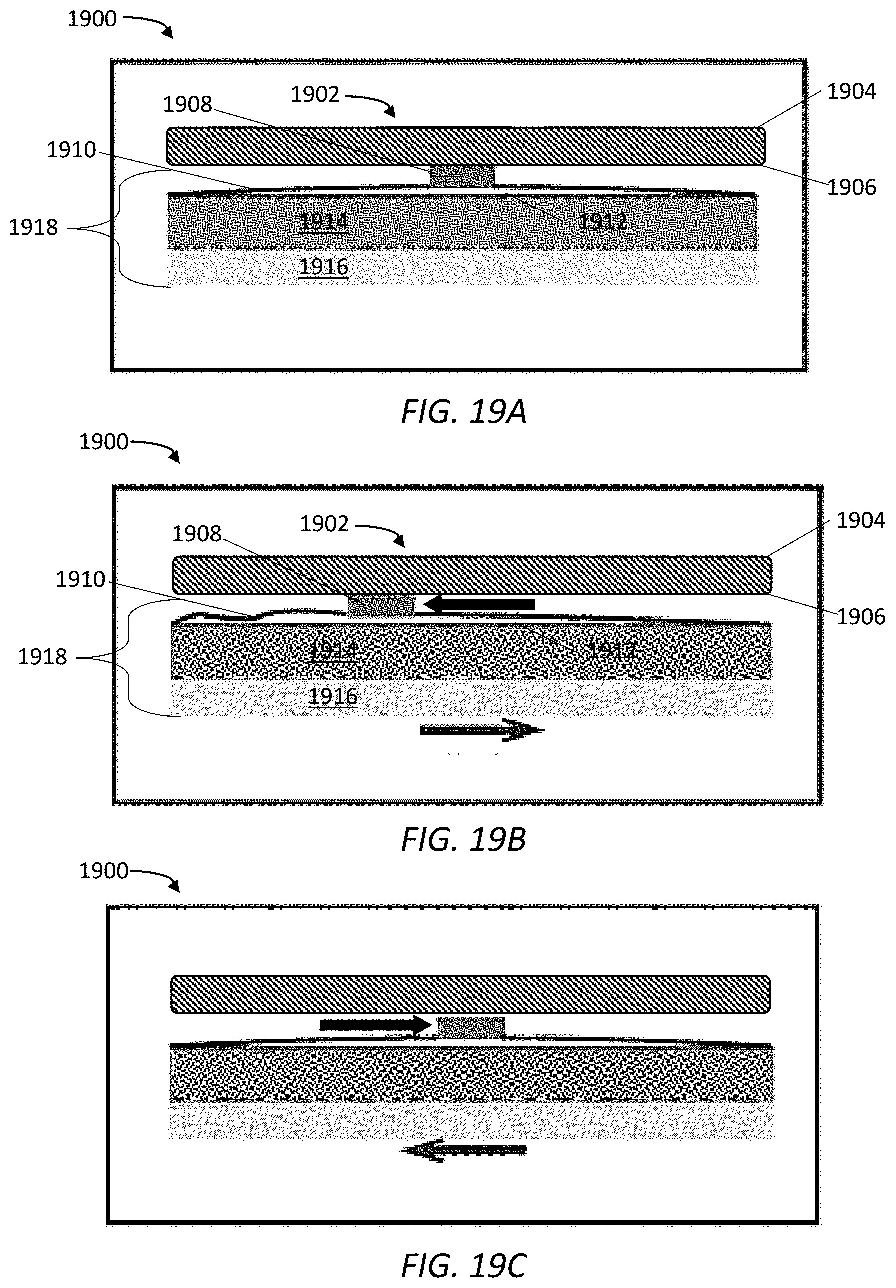
D00022

D00023

D00024

D00025

D00026

D00027

D00028

D00029

D00030

D00031

D00032

D00033

D00034

XML
uspto.report is an independent third-party trademark research tool that is not affiliated, endorsed, or sponsored by the United States Patent and Trademark Office (USPTO) or any other governmental organization. The information provided by uspto.report is based on publicly available data at the time of writing and is intended for informational purposes only.
While we strive to provide accurate and up-to-date information, we do not guarantee the accuracy, completeness, reliability, or suitability of the information displayed on this site. The use of this site is at your own risk. Any reliance you place on such information is therefore strictly at your own risk.
All official trademark data, including owner information, should be verified by visiting the official USPTO website at www.uspto.gov. This site is not intended to replace professional legal advice and should not be used as a substitute for consulting with a legal professional who is knowledgeable about trademark law.