Electronic Cigarette
HON; Lik
U.S. patent application number 17/129897 was filed with the patent office on 2021-04-15 for electronic cigarette. The applicant listed for this patent is FONTEM HOLDINGS 1 B.V.. Invention is credited to Lik HON.
| Application Number | 20210106053 17/129897 |
| Document ID | / |
| Family ID | 1000005300496 |
| Filed Date | 2021-04-15 |


| United States Patent Application | 20210106053 |
| Kind Code | A1 |
| HON; Lik | April 15, 2021 |
ELECTRONIC CIGARETTE
Abstract
An electronic cigarette includes a battery assembly and an atomizer assembly within a housing with the battery assembly electrically connected to the atomizer assembly. The housing has one or more air inlets. A liquid storage component is in contact with a porous component of the atomizer assembly, with the porous component having a run-through hole. A heating wire is in an air flow path through the run-through hole.
| Inventors: | HON; Lik; (Beijing, CN) | ||||||||||
| Applicant: |
|
||||||||||
|---|---|---|---|---|---|---|---|---|---|---|---|
| Family ID: | 1000005300496 | ||||||||||
| Appl. No.: | 17/129897 | ||||||||||
| Filed: | December 21, 2020 |
Related U.S. Patent Documents
| Application Number | Filing Date | Patent Number | ||
|---|---|---|---|---|
| 15167690 | May 27, 2016 | |||
| 17129897 | ||||
| 13740011 | Jan 11, 2013 | 9456632 | ||
| 15167690 | ||||
| 13079937 | Apr 5, 2011 | 8365742 | ||
| 13740011 | ||||
| 12226818 | Oct 29, 2008 | 8156944 | ||
| PCT/CN2007/001575 | May 15, 2007 | |||
| 13079937 | ||||
| Current U.S. Class: | 1/1 |
| Current CPC Class: | H01M 50/213 20210101; H01M 10/0525 20130101; H02J 7/0042 20130101; H05B 3/42 20130101; H05B 1/0297 20130101; H01M 10/425 20130101; A24F 40/40 20200101; A24F 40/46 20200101; H01M 50/20 20210101; H01M 10/46 20130101; H05B 1/0291 20130101; H01M 10/488 20130101; H05B 1/0244 20130101; H05B 3/06 20130101; H05B 3/03 20130101; F22B 1/284 20130101; H01M 2220/30 20130101; H02J 7/00 20130101; A24F 40/90 20200101 |
| International Class: | A24F 40/40 20200101 A24F040/40; H01M 50/213 20210101 H01M050/213; H01M 10/48 20060101 H01M010/48; H02J 7/00 20060101 H02J007/00; H05B 1/02 20060101 H05B001/02; H01M 10/42 20060101 H01M010/42; H01M 10/46 20060101 H01M010/46; H05B 3/03 20060101 H05B003/03; A24F 40/90 20200101 A24F040/90; H01M 50/20 20210101 H01M050/20; F22B 1/28 20060101 F22B001/28; A24F 40/46 20200101 A24F040/46; H05B 3/42 20060101 H05B003/42; H01M 10/0525 20100101 H01M010/0525; H05B 3/06 20060101 H05B003/06 |
Foreign Application Data
| Date | Code | Application Number |
|---|---|---|
| May 16, 2006 | CN | 200620090805.0 |
Claims
1. An electronic cigarette, comprising: a battery assembly having a battery and an operating indicator; an atomizer assembly in a housing; the atomizer assembly including a ceramic porous component set on a frame, the ceramic porous component having a cavity; liquid stored in the housing contacting the ceramic porous component; the atomizer assembly having a heating element on the ceramic porous component, the heating element electrically connected to the battery assembly, the heating element oriented perpendicular to a longitudinal axis of the housing; an air flow path in the atomizer assembly in part parallel to the longitudinal axis of the housing.
2. The electronic cigarette of claim 1 wherein the frame has a run-through hole and the air flow path extends through the run-through hole to an outlet.
3. The electronic cigarette of claim 1 wherein the heating element comprises a heating layer made of a conductive material.
4. The electronic cigarette of claim 1 further including an airflow sensor electrically connected to an electronic circuit board in the housing.
5. The electronic cigarette of claim 1 wherein the operating indicator comprises an LED at an end of the battery assembly.
6. The electronic cigarette of claim 1 wherein the ceramic porous component is configured to absorb the liquid and to move the liquid towards the heating element via capillary action.
7. An electronic cigarette, comprising: a battery assembly including a first housing and a rechargeable battery electrically connected to an electronic circuit board in the first housing; a charging connector and an operating indicator in the battery assembly, the charging connector and the operating indicator electrically connected to the electronic circuit board; an atomizer assembly electrically connected to the battery assembly; a second housing containing a liquid and having a vapor outlet, the second housing insertable into an open end of the first housing; at least one air inlet for allowing air to flow through the atomizer assembly; the atomizer assembly including a heating element electrically connected to the electronic circuit board, the heating element on a surface of a porous component, the heating element perpendicular to a longitudinal axis of the device, the porous component absorbing the liquid contained in the second housing; a frame having a first section having a first diameter, and a second section having a second diameter less than the first diameter, the second section coaxial with the first section, the second section engaging and aligning the porous component onto the frame; an air flow path from the at least one air inlet to the vapor outlet.
8. The electronic cigarette of claim 7 wherein the porous component has a cavity.
9. The electronic cigarette of claim 8 wherein the porous component comprises a ceramic material.
10. The electronic cigarette of claim 7 wherein the heating element comprises a metal wire.
11. The electronic cigarette of claim 7 further including an airflow sensor electrically connected to the electronic circuit board.
12. The electronic cigarette of claim 7 wherein the operating indicator comprises an LED at an end of the battery assembly.
13. The electronic cigarette of claim 7 where the frame has a through hole to allow air to flow through the frame.
14. An electronic cigarette, comprising: a battery assembly having a battery and an operating indicator; an atomizer assembly in a housing, the battery assembly electrically connected to the atomizer assembly; a ceramic porous component having a cavity; liquid stored in the housing contacting the ceramic porous component; the atomizer assembly having a heating element electrically connected to the battery, the heating element comprising a heating layer; and an air flow path in the atomizer assembly in part parallel to the longitudinal axis of the housing, the air flow path leading to an outlet.
15. The electronic cigarette of claim 14 wherein the ceramic porous component is supported on a frame having a run-through hole.
Description
CROSS-REFERENCE TO RELATED APPLICATIONS
[0001] This application is a continuation of U.S. patent application Ser. No. 15/167,690, filed May 27, 2016 and now pending, which is a continuation of U.S. patent application Ser. No. 13/740,011, filed Jan. 11, 2013, now U.S. Pat. No. 9,456,632, which is a continuation of U.S. patent application Ser. No. 13/079,937, filed Apr. 5, 2011, now U.S. Pat. No. 8,365,742, which is a divisional of U.S. patent application Ser. No. 12/226,818, filed Oct. 29, 2008, now U.S. Pat. No. 8,156,944, which is a 371 national filing of International Application No. PCT/CN2007/001575, filed May 15, 2007, which claims priority to Chinese Patent Application No. 200620090805.0, filed May 16, 2006. These applications are incorporated herein by reference.
BACKGROUND ART
[0002] Smoking causes serious respiratory system diseases and cancer, though it is hard to persuade the smokers to completely quit smoking.
[0003] Nicotine is the effective ingredient in cigarettes. Nicotine acts on the receptor of the central nervous system.
[0004] Nicotine is a micromolecular alkaloid, which is basically harmless to human bodies at a small dosage. Plus, its half life period is extremely short in blood. Tar is the major harmful substance in tobacco. Tobacco tar comprises several thousands of ingredients, dozens of which are carcinogenic substances.
[0005] To provide cigarette substitutes that contain nicotine but not harmful tar, many products have been used. These products are not as harmful as tar, but are absorbed very slowly. As a result, smokers can't be satisfied in full. In addition, the smokers are deprived of the "smoking" habit.
[0006] The electronic cigarettes currently available on the market may resolve the above-mentioned issue, though they are complicated in structure, they don't provide the ideal aerosol effects, and their atomizing efficiency is not high.
SUMMARY OF INVENTION
[0007] To overcome the above-mentioned disadvantages, an aerosol electronic cigarette includes a battery assembly, an atomizer assembly and a bottle assembly. The battery assembly connects with the atomizer assembly and both are located in a housing. The bottle assembly is located in one end of the housing and fits with the atomizer assembly.
[0008] The battery assembly may include the battery, an operating indicator, electronic circuit board, and airflow sensor, which are connected with the battery, and with the signal output of the airflow sensor connected to the electronic circuit board.
[0009] A component for liquid storage of the cigarette bottle assembly stores the nicotine liquid. Smokers can enjoy the feel of smoking, with no fire hazard since there is no need for igniting.
DESCRIPTION OF DRAWINGS
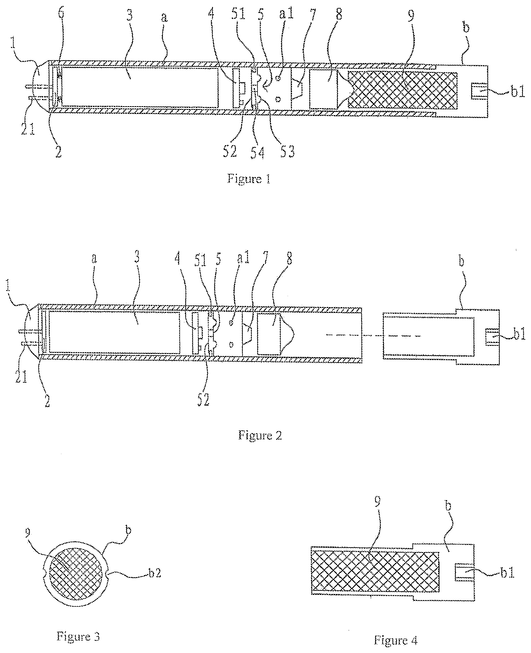
[0010] FIG. 1 is the side section view of an electronic cigarette.
[0011] FIG. 2 is the section view of the housing (a) separated from the cigarette bottle assembly.
[0012] FIG. 3 is the diagram of the axial structure of the cigarette bottle assembly, illustrating the ventilating groove on the peripheral surface of the cigarette holder housing.
[0013] FIG. 4 is the side section view of the cigarette bottle assembly, illustrating the structure of the air channel.
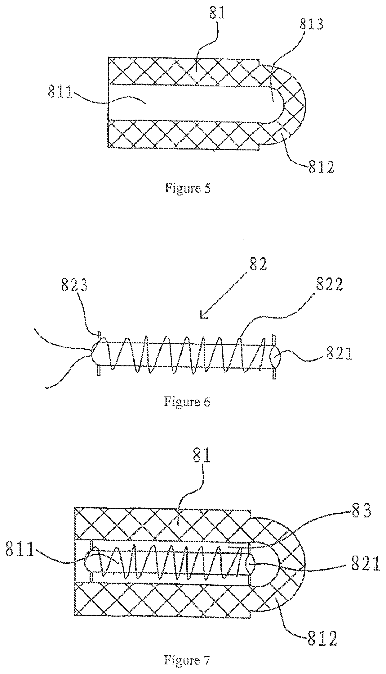
[0014] FIG. 5 is the side section view of a porous component of the atomizer.
[0015] FIG. 6 is the diagram of the structure of an electric heating rod of the atomizer.
[0016] FIG. 7 is the side section of the atomizer, illustrating the locations of and connection relation between the electric heating rod and porous component.
[0017] FIG. 8 is the diagram of the atomizer, illustrating the locations of and connection relation between the electric heating rod and porous component.
[0018] FIG. 9 is the section view of a check valve.
[0019] FIG. 10 is the front section view of a restriction component in a second embodiment.
[0020] FIG. 11 is a diagram of the axial structure of the cigarette bottle assembly in another embodiment.
[0021] FIG. 12 is a sectional view taken along line A-A of FIG. 11.
[0022] FIG. 13 is a diagram of the structure of the electric heating rod of the atomizer in another embodiment.
[0023] FIG. 14 is a section view of the porous component of the atomizer in the embodiment shown in FIG. 13.
[0024] FIG. 15 is a diagram of the axial structure of FIG. 14.
[0025] FIG. 16 is a side section view of the atomizer in the embodiment of FIG. 13, illustrating the locations of and connection relation between the electric heating rod and porous component.
[0026] FIG. 17 is a diagram of the axial structure of the atomizer in another embodiment.
[0027] FIG. 18 is the side section view of the atomizer shown in FIG. 17.
[0028] FIG. 19 is the side section view of another electronic cigarette embodiment.
[0029] FIG. 20 is the electric circuit diagram of an electronic cigarette.
[0030] FIG. 21 is another electric circuit diagram of an electronic cigarette.
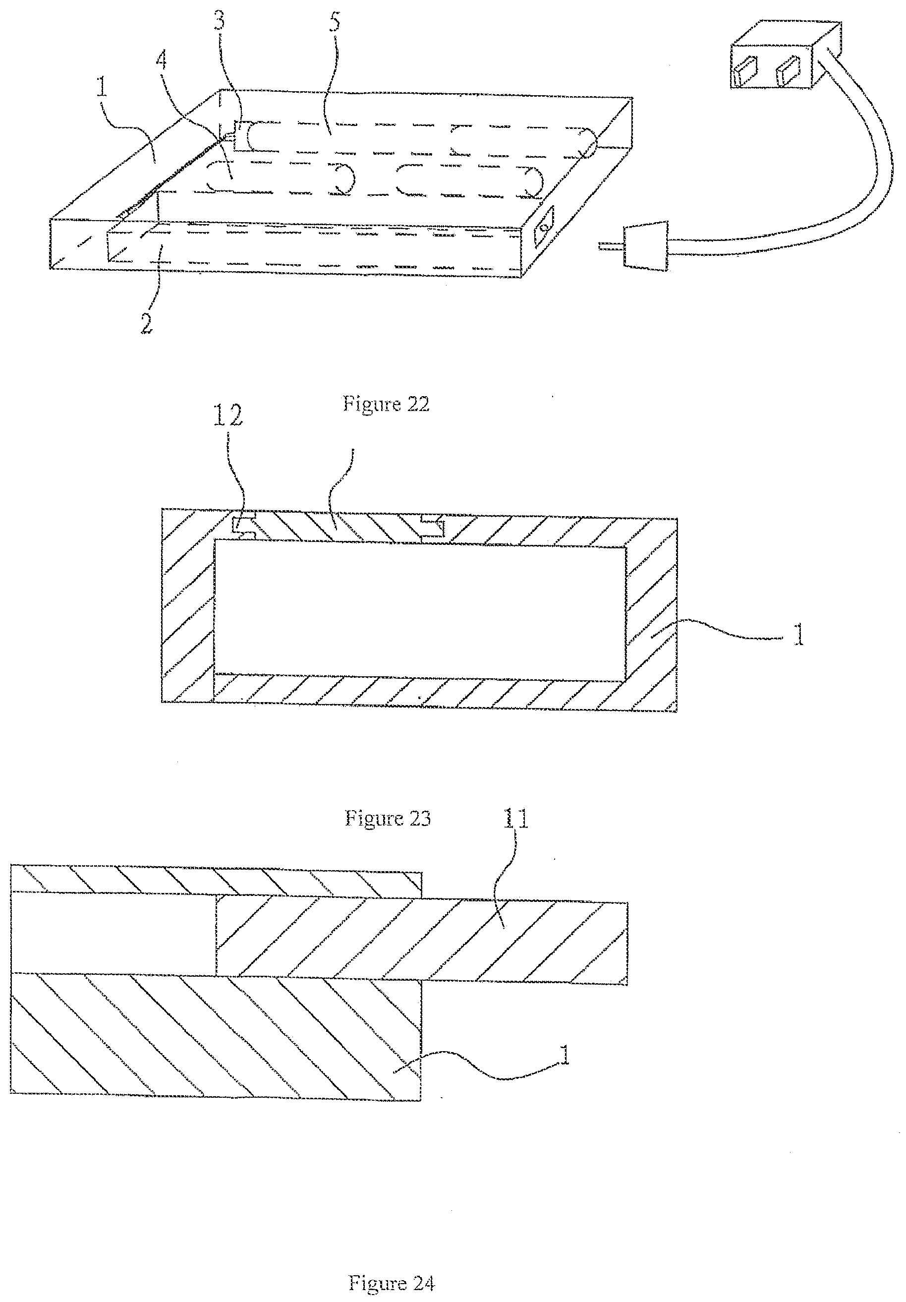
[0031] FIG. 22 is a diagram of a charging device, illustrating the locations of and connection relation of various internal parts.
[0032] FIG. 23 is the side section view of the charging device.
[0033] FIG. 24 is the diagram of the front structure of the charging device.
SPECIFIC MODE FOR CARRYING OUT THE INVENTION
[0034] As shown in FIGS. 1-10, an aerosol electronic cigarette includes a battery assembly, an atomizer assembly and a cigarette bottle assembly, and also includes a shell or housing (a), which is hollow and integrally formed. The battery assembly connects with the atomizer assembly and both are located in the shell. The cigarette bottle assembly is located in one end of the shell, which is detachable. The cigarette bottle assembly fits with the atomizer assembly. The shell has through-air-inlets (a1).
[0035] In this specific embodiment, the battery assembly includes the battery, and the operating indicator (1), electronic circuit board (4), and airflow sensor (5), which are connected with the battery. It also includes a check valve (7). The signal output of the airflow sensor (5) is connected with the said electronic circuit board (4). The battery is a rechargeable battery (3), which may be either a rechargeable polymer lithium ion battery or a rechargeable lithium ion battery. The airflow sensor (5) may be alternatively a semiconductor force-sensitive chip capacitance sensor or an inductance sensor.
[0036] The rechargeable battery (3) has a flexibly connected charging plug (2). The blades (21) of the charging plug (2) come out of the other end of the shell (a). Between the charging plug (2) and rechargeable battery (3) is a spring (6), which lies against the body of the rechargeable battery (3) on one end, while its free end lies against the charging plug (2), forming a flexible structure, which buffers the charging plug (2) when plugged for charging, thus protecting the rechargeable battery against any damage. Of course, the rechargeable battery (3) in this embodiment has a charging slot on it, which replaces the structure of charging plug (2) to perform the charging function and protect the rechargeable battery (3) against any damage. The operating indicator (1) is a LED. In this embodiment, there are two LEDs. The electronic circuit board (4) includes an electronic switch circuit, which controls the electric circuit according to the input signals, so that the rechargeable battery (3) electrifies the electric heating rod (82) inside the atomizer (8) and the LEDs as well.
[0037] As shown in FIGS. 1 and 2, the airflow sensor (5) has a silica gel corrugated membrane (53), which connects with magnetic steel (54) with a reed relay (52) on one of its ends. Both ends of the said reed relay (52) correspond to the relay electrodes (51) respectively.
[0038] As shown in FIGS. 5-8, the atomizer assembly is an atomizer (8), which includes a porous component (81) and a heating rod (82). The body of the porous component (82) has a run-through atomizing chamber (811). The diameter of the electric heating rod (82) is less than the diameter of the atomizing chamber (811). The electric heating rod (82) enters into the atomizing chamber (811), and there is a clearance between the electric heating rod (82) and interior wall of the atomizing chamber (811), which forms a negative pressure cavity (83). One end of the porous component (81) fits with the cigarette bottle assembly. As FIGS. 5, 7 and 8 show, the porous component (81) has a protuberance (812) on the other end, and the protuberance (812) fits with the cigarette bottle assembly. The protuberance (812) is a protruding half sphere, on the side of which there is a run-through hole (813) connecting to the atomizing chamber (811). Of course, the protuberance (812) may also be a taper, rectangle or any other shape. The porous component (81) is made of foamed nickel, stainless steel fiber felt, macromolecular polymer foam or foamed ceramics, providing the remarkable capabilities in liquid absorption and diffusion, and the ability to absorb the liquid stored in the cigarette bottle assembly.
[0039] As shown in FIG. 6, the electric heating rod (82) includes a cylinder (821). The heating wire (822) is wound on the wall of the cylinder (821). On the wall of both ends of the cylinder (821), there are mandrils (823) respectively, which lie against the interior wall of the atomizing chamber (811) of the porous component (81). There is a negative pressure cavity (83) between the electric heating rod and interior wall of the atomizing chamber.
[0040] The heating wire is made of platinum wire, nickel-chromium alloy wire or iron-chromium alloy wire containing rare earth, or is flaked. The electric heating rod (82) may alternatively have on its peripheral wall the heating layer made of electrically conductive ceramic PTC material, to replace the heating wire.
[0041] In this embodiment, the battery assembly and atomizer assembly are mutually connected and then installed inside the integrally formed shell (a) to form a one-piece part. The rechargeable battery (3) may be charged without frequent change of battery. The user just needs to plug the cigarette bottle assembly into the open end of the shell (a), for easy use and very easy change.
[0042] As shown in FIGS. 3 and 4, the cigarette bottle assembly includes a hollow cigarette holder shell (b), and a perforated component for liquid storage (9) inside the shell (b). The perforated component for liquid storage (9) is made of such materials as PLA fiber, terylene fiber or nylon fiber, which are suitable for liquid storage. Alternatively, it may be plastic foam molding or column of multi-layer plates made through plastic injection with polyvinyl chloride, polypropylene and polycarbonate. One end of the cigarette holder shell (b) plugs into the shell (a), and the outer peripheral surface of the cigarette holder shell (b) has an inward ventilating groove (b2). On one end surface of the cigarette holder shell (b), there is an air channel (b1) extending inward. The air channel (b1) is located in the center on the surface of one end of shell (b).
[0043] As shown in FIGS. 1-9, one end of the porous component (81) lies against one end surface of the perforated component for liquid storage (9), and contacts the perforated component for liquid storage (9). It absorbs the cigarette liquid from the perforated component for liquid storage (9). When the smoker smokes, the cavity of the cigarette holder shell (b) is in the negative pressure state. In the shell (b), one end of the airflow sensor (5) forms a normal pressure cavity, while the other end forms a negative pressure cavity. The air pressure difference between the normal pressure cavity and negative pressure cavity or the high-speed airflow enables the magnetic steel (54) of the airflow sensor (5) to drive the reed relay (52) to contact the relay electrode (51).
[0044] As shown in FIG. 20, the electric circuit is electrified, and the electronic switch circuit on the electronic circuit board (4) is electrified. Thus, the rechargeable battery (3) starts to electrify the electric heating rod (82) inside the atomizer (8), and at the same time, the LEDs, which are electrified by the rechargeable battery (3), emit light. The air enters the normal pressure cavity through the air inlet (a1), passes the check valve (7) via the airflow passage in the airflow sensor (5), and flows to the negative pressure cavity (83) in the atomizer (8). Since the negative pressure cavity (83) provides the negative pressure compared with the outside, the air flow sprays into it, bringing the cigarette liquid from the porous component (81) to spray into the negative pressure cavity (83) in the form of fine drops.
[0045] In the meantime, the electric heating rod (82) is electrified by the rechargeable battery (3) under the control of electronic circuit board (4), to heat the fine drops for atomization. After atomization, the big-diameter fine drops are re-absorbed by the porous component (81) under the action of vortex, while the small-diameter fine drips are suspended in the airflow to form aerosol, which is discharged through the negative pressure cavity (83) and run-through hole (813), flows into the cigarette holder shell (b) of the cigarette bottle assembly, and is absorbed by the air channel (b1). When the aerosol enters the cigarette holder shell (b), multiple small liquid drops are condensed into bigger ones, which fall into the clearance between the cigarette holder shell (b) and air channel (b1) without being absorbed by the air channel (b1). The perforated component for liquid storage (9) of the cigarette bottle assembly and the porous component (81) of the atomizer (8) contact each other to achieve the capillary impregnation for liquid supply.
[0046] The unit and its connecting structure of this invention may also be loaded with drugs for delivery to the lung.
[0047] As shown in FIGS. 22, 23 and 24, the electronic cigarette (5) is held in a charging device. The charging device includes a case (1), which contains an auxiliary charging storage battery (2) inside it, and holds the electronic cigarette (5) and the charger (3) for the rechargeable battery embedded in the electronic cigarette (5), as well as the power supply circuit. The power inputs of the auxiliary charging storage battery (2) and charger (3) are connected with the power supply respectively. The charger (3) in this embodiment is a constant voltage & current charger. It may be a GY5210 charger, or any other constant voltage & current charger. The case (1) has a spare liquid supply bottle (4) in it. The power output of the auxiliary charging storage battery (2) is connected with the power input of the charger (3). The power output of the charger (3) is a charging slot (31), which fits with the charging plug of the rechargeable battery inside the electronic cigarette, or a charging plug, which fits with the charging slot of the rechargeable battery.
[0048] As shown in FIGS. 23 and 24, on the body of the shell (1), there is a pair of slide ways (12) corresponding to the position of the electronic cigarette, and on the slide ways, there is a slide cover (11).
[0049] In the second preferred embodiment, a restriction component (10), which is detachable, is set on one end of the porous component (81). There is a restriction hole (101) on the body of the restriction component (10). The restriction hole (101) corresponds to the atomizing chamber (811). The pore diameter of the restriction hole is less than the inner diameter of the atomizing chamber (811) to the extent that the size of the restriction component (10) installed on the porous component (81) varies, for the purpose of airflow capacity control. On the basis of different applications, the restriction component of different sizes and pore diameters may be used.
[0050] In the third preferred embodiment of this utility model, as shown in 11 and 12, on the outer peripheral wall of the cigarette shell (b), there is a protruding rib (b2) that is evenly partitioned. The perforated component for liquid storage (9) enters the cigarette holder shell (b) and lies against the protruding rib (b2). Thus, there appears a clearance between the outer peripheral surface of the perforated component for liquid storage (9) and the interior wall of the shell (b). The clearance is for connection the shell (a) and cigarette holder shell (b). When the user smokes, the air channel (b1) absorbs the air to cause airflow inside the shell (a), thus triggering the airflow sensor (5) and eventually starting the electronic cigarette. Also, the atomizer (8) works to atomize the cigarette liquid and produce gas flow, which enters the cigarette holder shell (b).
[0051] In the fourth preferred embodiment, as shown in FIGS. 13, 14, 15 and 16, on one end of the cylinder (821), there is a fixed plate (84), whose outer peripheral wall has partitioned supports (841). The outer ends of the supports (841) lie against the interior wall of the shell (a), thus suspending the cylinder (821), which is connected with the fixed plate (84), in the cavity of the shell (a). On the surface of the fixed plate (84), there is a mandril (842), whose front end lies against one end of the porous component (81), so that the fixed plate (84) is separated from the atomizing chamber (811) of the porous component (81). As a result, the run-through hole on one end of the atomizing chamber (811) won't be blocked, and the mist generated in the atomizing chamber (811) can be dispersed. One end of the porous component (81) has two protuberances (812) at the outlet of the atomizing chamber (811). Between the two protuberances (812) is a clearance. The two protuberances (812) lie against the perforated component for liquid storage (9).
[0052] In the fifth preferred embodiment, as shown in FIGS. 17 and 18, the atomizer assembly is an atomizer (8), which includes a frame (82), the porous component (81) set on the frame (82), and the heating wire (83) wound on the porous component (81). The frame (82) has a run-through hole (821) on it. The porous component (81) is wound with heating wire (83) in the part that is on the side in the axial direction of the run-through hole (821). One end of the porous component (81) fits with the cigarette bottle assembly. The porous component (81) is made of foamed nickel, stainless steel fiber felt, macromolecular polymer foam or foamed ceramics.
[0053] In the sixth preferred embodiment, as shown in FIG. 19, the airflow sensor (5) has a silica gel corrugated membrane (53), which connects with magnetic steel (54) with a Hall element (52), or a magneto-diode or a magneto-triode on one of its ends. FIG. 21 shows the electric circuit of the electronic cigarette of this solution.
* * * * *
D00000
D00001
D00002
D00003
D00004
D00005
D00006
D00007
D00008
XML
uspto.report is an independent third-party trademark research tool that is not affiliated, endorsed, or sponsored by the United States Patent and Trademark Office (USPTO) or any other governmental organization. The information provided by uspto.report is based on publicly available data at the time of writing and is intended for informational purposes only.
While we strive to provide accurate and up-to-date information, we do not guarantee the accuracy, completeness, reliability, or suitability of the information displayed on this site. The use of this site is at your own risk. Any reliance you place on such information is therefore strictly at your own risk.
All official trademark data, including owner information, should be verified by visiting the official USPTO website at www.uspto.gov. This site is not intended to replace professional legal advice and should not be used as a substitute for consulting with a legal professional who is knowledgeable about trademark law.