Temperature Control Device For Controlling The Temperature Of An Electric Device
Moser; Michael ; et al.
U.S. patent application number 17/064590 was filed with the patent office on 2021-04-08 for temperature control device for controlling the temperature of an electric device. The applicant listed for this patent is Mahle International GmbH. Invention is credited to Michael Moser, Thorsten Mueller, Daniel Rothmaier, Volker Schall, Dominique Weinmann.
| Application Number | 20210104792 17/064590 |
| Document ID | / |
| Family ID | 1000005162042 |
| Filed Date | 2021-04-08 |


| United States Patent Application | 20210104792 |
| Kind Code | A1 |
| Moser; Michael ; et al. | April 8, 2021 |
TEMPERATURE CONTROL DEVICE FOR CONTROLLING THE TEMPERATURE OF AN ELECTRIC DEVICE
Abstract
A temperature control device for controlling a temperature of an electric device may include at least one fluid channel through which a temperature control fluid may be flowable. The at least one fluid channel may be delimited, at least partially, by at least one volume-variable casing of a flexible material. The temperature control device may further include at least one fastening device. The at least one fastening device may surround a fluid chamber through which the temperature control fluid may be flowable. The at least one casing may be coupled to the at least one fastening device such that the fluid chamber is in fluid communication with the at least one fluid channel.
| Inventors: | Moser; Michael; (Ellwangen, DE) ; Mueller; Thorsten; (Benningen, DE) ; Rothmaier; Daniel; (Maulbronn, DE) ; Schall; Volker; (Hemmingen, DE) ; Weinmann; Dominique; (Rottenburg, DE) | ||||||||||
| Applicant: |
|
||||||||||
|---|---|---|---|---|---|---|---|---|---|---|---|
| Family ID: | 1000005162042 | ||||||||||
| Appl. No.: | 17/064590 | ||||||||||
| Filed: | October 6, 2020 |
| Current U.S. Class: | 1/1 |
| Current CPC Class: | H01M 10/613 20150401; H01M 10/6557 20150401 |
| International Class: | H01M 10/6557 20060101 H01M010/6557; H01M 10/613 20060101 H01M010/613 |
Foreign Application Data
| Date | Code | Application Number |
|---|---|---|
| Oct 7, 2019 | DE | 102019215336.4 |
Claims
1. A temperature control device for controlling a temperature of an electric device, comprising: at least one fluid channel through which a temperature control fluid is flowable, the at least one fluid channel delimited at least partially by at least one volume-variable casing of a flexible material; at least one fastening device surrounding a fluid chamber through which the temperature control fluid is flowable; and wherein the at least one casing is coupled to the at least one fastening device such that the fluid chamber is in fluid communication with the at least one fluid channel.
2. The temperature control device according to claim 1, wherein the at least one fastening device includes two fastening devices between which the at least one casing is arranged such that a first fastening device of the two fastening devices forms a temperature control fluid inlet and a second fastening device of the two fastening devices forms a temperature control fluid outlet for the temperature control fluid directable through the at least one fluid channel.
3. The temperature control device according to claim 1, wherein the at least one fastening device is configured as a fastening strip, along a longitudinal direction of which the at least one casing is coupled.
4. The temperature control device according to claim 1, wherein: the at least one fastening device includes at least two fastening devices configured as fastening strips; and the at least two fastening devices are arranged adjacent to one another and define an intermediate space configured to receive the electric device which is to be temperature-controlled.
5. The temperature control device according to claim 1, wherein the at least one fastening device includes a connecting piece for formation of at least one of a temperature control fluid inlet and a temperature control fluid outlet.
6. The temperature control device according to claim 3, wherein the at least one fastening device is structured as a hood.
7. The temperature control device according to claim 1, wherein: the at least one fastening device is configured as a fastening frame; the fastening frame surrounds a through-opening in a circumferential manner; and the through-opening is closed on both sides by the at least one casing.
8. The temperature control device according to claim 1, wherein: the at least one fastening device is configured as a fastening strip through which the temperature control fluid is flowable; a fastening frame is arranged on the fastening strip and, together with the at least one casing, delimits the at least one fluid channel.
9. The temperature control device according to claim 8, wherein the fastening frame is configured to not be able to be flowed through by the temperature control fluid.
10. The temperature control device according to claim 8, wherein a flow-guiding element is arranged on the fastening strip and projects into the at least one fluid channel.
11. The temperature control device according to claim 10, wherein: the fastening frame has a rectangular geometric shaping with two longitudinal sides and two broad sides; the flow-guiding element has a T-shaped geometry with a foot shank and a top shank; and the foot shank extends parallel to one of (i) a broad side of the two broad sides and (ii) a longitudinal side of the two longitudinal sides, and the top shank extends along the other of (i) the broad side and (ii) the longitudinal side.
12. The temperature control device according to claim 8, wherein the at least one casing is coupled circumferentially on the fastening frame.
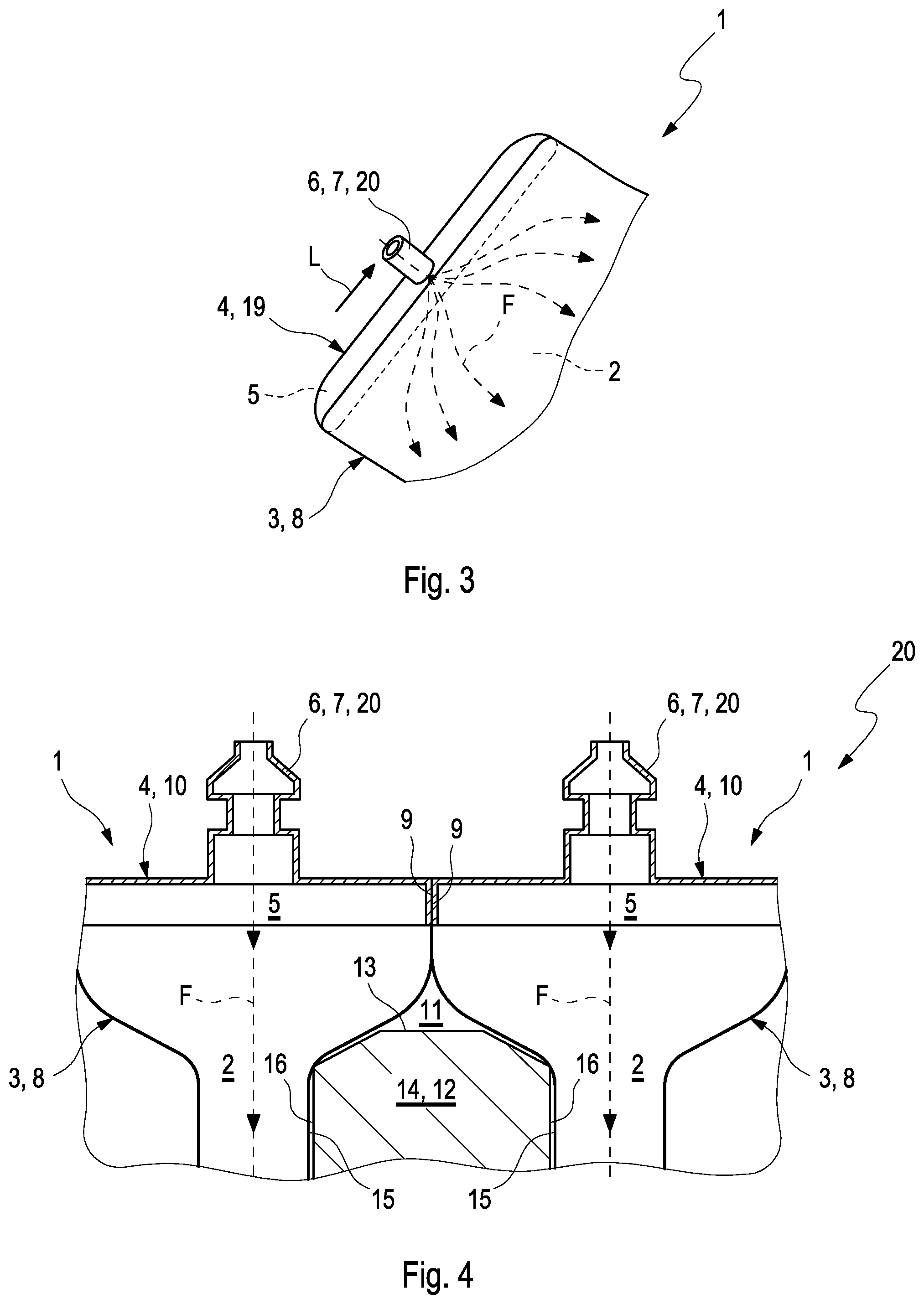
13. The temperature control device according to claim 1, wherein the at least one casing is configured as at least one of a bag and a cushion.
14. The temperature control device according to claim 1, wherein the flexible material is a foil.
15. The temperature control device according to claim 1, wherein the at least one casing is configured such that a volume delimited by the at least one casing and forming the at least one fluid channel is greater when the temperature control fluid is flowing through the at least one fluid channel than which no when the temperature control fluid is not flowing through the at least one fluid channel.
16. A battery arrangement, comprising: at least one battery having a battery housing; a temperature control device including: at least one fluid channel through which a temperature control fluid is flowable, the at least one fluid channel delimited at least partially by at least one volume-variable casing composed of a flexible material; and at least one fastening device surrounding a fluid chamber through which the temperature control fluid is flowable; wherein the at least one casing is coupled to the at least one fastening device such that the fluid chamber is in fluid communication with the at least one fluid channel; and wherein the at least one casing, at least when flowed through by the temperature control fluid, lies with at least one contact zone flat against at least one housing section of the battery housing.
17. The battery arrangement according to claim 16, wherein: the at least one battery includes a plurality of batteries; the at least one fastening device includes a plurality of fastening devices arranged to define a plurality of intermediate spaces; each of the plurality of intermediate spaces is defined between two adjacent fastening devices of the plurality of fastening devices; and the at least one casing, at least when flowed through by the temperature control fluid, is squeezed between two battery housings of two batteries of the plurality of batteries, the two batteries arranged in adjacent intermediate spaces of the plurality of intermediate spaces.
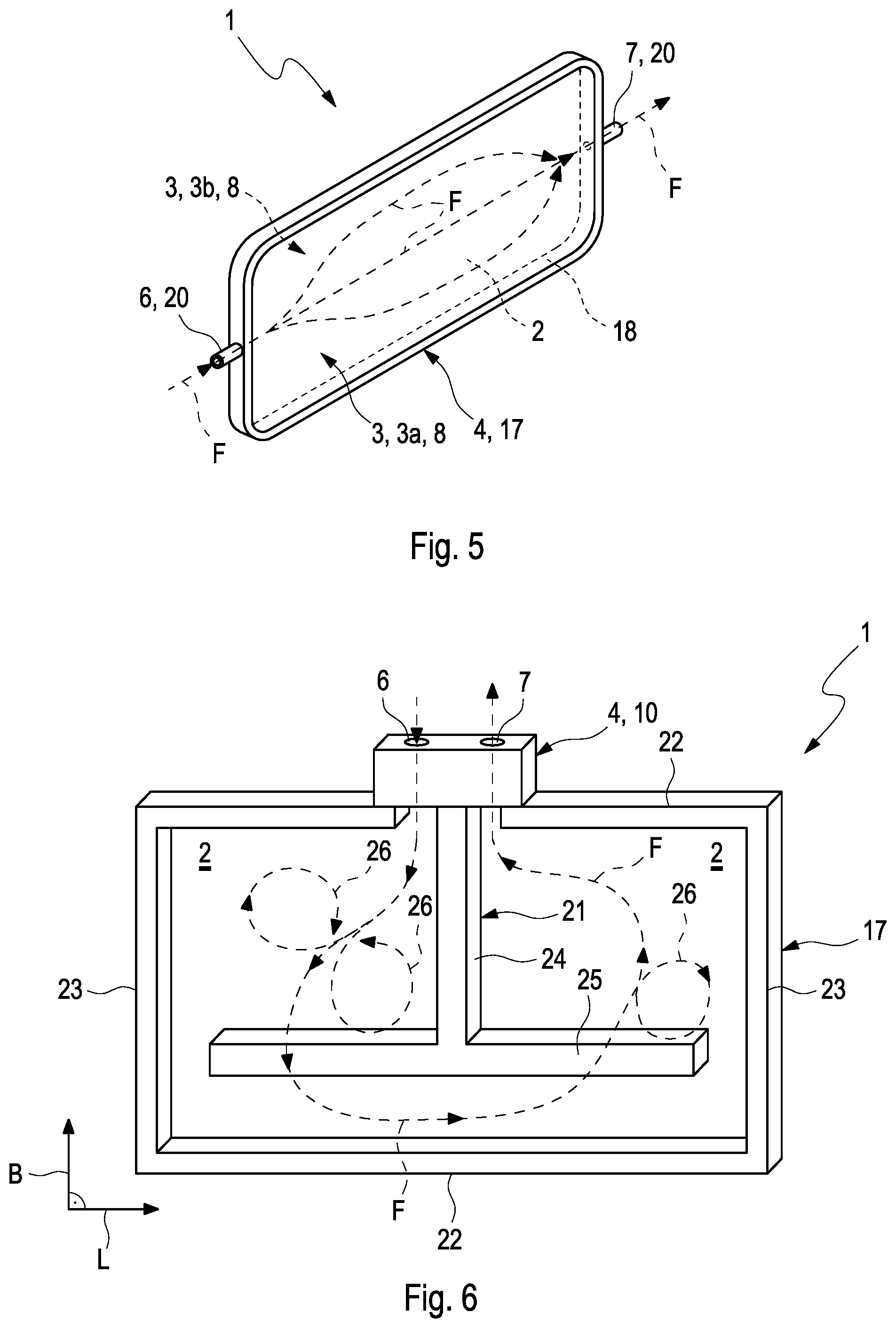
18. A temperature control device for controlling a temperature of an electric device, comprising: at least one volume-variable casing composed of a flexible material; the at least one volume-variable casing at least partially delimiting a fluid channel through which a temperature control fluid is flowable, the at least one fluid channel having a variable volume; a plurality of fasteners defining a plurality of non-volume-variable fluid chambers through which the temperature control fluid is flowable, each fastener of the plurality of fasteners defining a fluid chamber of the plurality of fluid chambers; the plurality of fasteners arranged in contact with one another; and wherein the at least one casing is disposed between and coupled to the plurality of fasteners such that the at least one fluid channel is in fluid communication with the plurality of fluid chambers.
19. The temperature control device according to claim 1, wherein: the at least one fastening device includes a fastening strip and a fastening frame; the fastening strip extends between and connects opposite ends of the fastening frame such that the fastening strip and the fastening frame collectively define the fluid chamber; and a flow-guide protrudes from the fastening strip into the fluid chamber, the flow-guide including a foot shank and a top shank, the foot shank extending between and coupling the top shank to the fastening strip such that the flow-guide has a T-shaped geometry.
20. The temperature control device according to claim 8, wherein the at least one casing is coupled to and completely surrounds the fastening frame circumferentially.
Description
CROSS-REFERENCE TO RELATED APPLICATIONS
[0001] This application claims priority to German Patent Application No. DE 10 2019 215 336.4, filed on Oct. 7, 2019, the contents of which is hereby incorporated by reference in its entirety.
TECHNICAL FIELD
[0002] The invention relates to a temperature control device for controlling the temperature of an electric device. The invention relates furthermore to a battery arrangement with such a temperature control device.
BACKGROUND
[0003] In modem vehicles, efficient electrical energy stores such as lithium-ion batteries for example are coming increasingly into use. For a correct functioning of these energy stores, it is absolutely necessary that their operating temperature neither exceeds a predetermined maximum value nor falls below a predetermined minimum value. It is therefore known to control the temperature of the electric device with the aid of a suitable temperature control device.
[0004] Against this background, DE 10 2011 084 000 A1 describes a device for guiding a cooling fluid for cooling an electric component. The device comprises a fluid-guiding chamber for guiding a cooling fluid, which can be closed in a fluid-tight manner by means of an at least partially flexible cover. This flexible cover forms a heat transfer region for heat conduction between the cooling fluid and the electric component which is to be cooled.
SUMMARY
[0005] It is an object of the present invention to create an improved embodiment for a temperature control device, which in particular has an improved efficiency in controlling the temperature of electric devices, in particular of batteries.
[0006] This problem is solved by the subject matter of the independent claim(s). Preferred embodiments are the subject matter of the dependent claim(s).
[0007] The basic idea of the invention accordingly is to delimit at least partially through a volume-variable casing a fluid channel which can be flowed through by a temperature control fluid for controlling the temperature--therefore for cooling or heating an electric device--for example an electric battery. Said volume variability of such a casing allows the casing to be able to lie flat against said electric device or respectively its housing. Through this becomes whereby the thermal coupling can be improved between the coolant, which is directed through the casing, and the temperature-controlled device which is to be cooled. This leads to an improved efficiency of the temperature control device.
[0008] A temperature control device according to the invention for controlling the temperature of an electric device, in particular an electric battery, comprises at least one fluid channel able to be flowed through by a temperature control fluid, which fluid channel is delimited at least partially by at least one volume-variable casing of a flexible material. Furthermore, the temperature control device comprises at least one fastening device which surrounds a preferably non-volume-variable fluid chamber able to be flowed through by the temperature control fluid and on which the casing is fastened. The fastening device and the casing are coordinated with one another here in such a way that the fluid chamber communicates fluidically with the at least one fluid channel.
[0009] According to an advantageous further development, two fastening devices are present, between which the casing is arranged so that a first fastening device forms a temperature control fluid inlet and a second fastening device forms a temperature control fluid outlet for the temperature control fluid which is to be directed through the fluid channel. This permits a linear throughflow of the casing between temperature control fluid inlet and temperature control fluid outlet.
[0010] Expediently, the at least one fastening device can be configured in the manner of a fastening strip which has an elongated geometric shaping and the longitudinal sides of which extend along a longitudinal direction. In this variant, the at least one casing is fastened along the longitudinal direction on the fastening strip or respectively fastening device. In this way, the volume-variable casing can be fixed in the desired installation space in a mechanically stable manner.
[0011] According to an advantageous further development, at least two fastening devices are provided which are configured as fastening strips. In this further development, the at least two fastening devices or respectively fastening strips are arranged adjacent to one another with the formation of an intermediate space for receiving the electric device which is to be temperature-controlled. This variant permits a temperature control on both sides of the electric device which is to be temperature-controlled by means of the two casings lying opposite one another transversely to the intermediate space.
[0012] According to an advantageous further development, on the at least one fastening device a connecting piece is formed for the formation of the temperature control fluid inlet or temperature control fluid outlet. This further development is particularly compact in construction and is also cost-efficient in manufacture.
[0013] According to another preferred embodiment, the fastening device can be configured as a hood. If the casing is fastened on said hood, then in this way a particularly great flow cross-section is realized between the fastening device and the fluid channel which is delimited by the casing.
[0014] According to another preferred embodiment, the at least one fastening device is configured as a fastening frame which circumferentially surrounds, preferably completely, a through-opening, which is closed on both sides by the casing. In this case, the casing can be configured having two parts. However, this embodiment is particularly suitable when the fastening frame is arranged with the casing in an intermediate space between two adjacent batteries or respectively battery housings which are to be temperature-controlled. A first part of the two-part casing can therefore lie flat against a first battery or respectively a first battery housing, the second part of the casing against the adjacent second battery or respectively the adjacent second battery housing.
[0015] According to a preferred embodiment, the fastening device is configured as a fastening strip which is able to be flowed through by the temperature control fluid. In this embodiment, the fastening strip is connected with a fastening frame which, together with the casing, delimits the fluid channel.
[0016] According to another preferred embodiment, the fastening frame is not configured to be able to be flowed through by the temperature control fluid. In this embodiment, the structure of the fastening frame can be configured particularly simply, from which cost advantages result in the manufacture thereof.
[0017] According to an advantageous further development, at least one flow-guiding element is arranged on the fastening strip, which flow-guiding element projects into the fluid channel. In this way, the thermal interaction of the fluid can be improved for heat absorption or heat dissipation, and therefore the efficiency of the temperature control device can be increased.
[0018] Expediently, the fastening frame can be provided with a substantially rectangular geometric shaping with two longitudinal sides and with two broad sides. In this variant, the flow-guiding element has a T-shaped geometry with one foot shank and one top shank. In this variant, the foot shank extends parallel to the broad side, and the top shank extends along the longitudinal side, or vice versa.
[0019] Particularly preferably, the casing is mounted circumferentially, preferably completely circumferentially, on the fastening frame. In this way, the casing can be fixed in the installed state in a particularly stable manner in the desired installation space.
[0020] Particularly preferably, the at least one casing can be configured in the manner of a bag or in the manner of a cushion. Such a configuration as a bag or respectively cushion makes it possible, with corresponding pressurization of the temperature control fluid flowing through the casing, to increase the volume of the casing so that it surrounds in a flat manner the electric device which is to be temperature-controlled, or respectively lies flat against the latter. In this way, the thermal coupling of the temperature control fluid with the electric device which is to be temperature-controlled is improved.
[0021] Expediently, the flexible material of the casing can be a foil. In this way, in particular bags or respectively cushions with variable volume can be realized.
[0022] According to a further preferred embodiment, the volume-variable casing is configured in such a way that the volume limited by the casing and forming the fluid channel is greater in a state when flowed through by the temperature control fluid than in a state in which no temperature control fluid is flowing through the fluid channel. In this way, it is achieved that intermediate spaces present between the casing and the electric device which is to be temperature-controlled are partially or even completely closed as soon as the casing is flowed through by the temperature control fluid. In this way, the thermal contact surface between the device which is to be temperature-controlled and the casing which is flowed through the by the temperature control fluid is improved.
[0023] The invention also relates to a battery arrangement with at least one battery, having a battery housing, and a temperature control device according to the invention, explained above. The advantages of the temperature control device according to the invention, which are explained above, are therefore transferred also to the battery arrangement according to the invention. According to the invention, the volume-variable casing, at least in a state when flowed through by the temperature control fluid, lies with at least one contact zone in a flat manner against at least one housing section of the battery housing.
[0024] According to a preferred embodiment, the casing, at least in a state when flowed through by the temperature control fluid, is squeezed between two battery housings arranged in adjacent intermediate spaces. In this way, a flat contact is achieved between the casing and the device which is to be temperature-controlled, whereby the efficiency of the temperature control device can be increased.
[0025] Further important features and advantages of the invention will emerge from the subclaims, from the drawings and from the associated figure description with the aid of the drawings.
[0026] It shall be understood that the features mentioned above and to be further explained below are able to be used not only in the respectively indicated combination, but also in other combinations or in isolation, without departing from the scope of the present invention.
[0027] Preferred example embodiments of the invention are illustrated in the drawings and are explained in further detail in the following description, wherein the same reference numbers refer to identical or similar or functionally identical components.
BRIEF DESCRIPTION OF THE DRAWINGS
[0028] There are shown, respectively schematically:
[0029] FIG. 1 shows a first example of a temperature control device according to the invention with a casing of variable volume arranged between two fastening devices,
[0030] FIG. 2 shows a second example of a temperature control device according to the invention, in which the fastening device is configured as a fastening strip,
[0031] FIG. 3 shows a second example of a temperature control device according to the invention, in which the fastening device has a hood-like geometric shaping,
[0032] FIG. 4 shows an example of a battery arrangement according to the invention with temperature control devices, the fastening devices of which is respectively configured as a fastening strip,
[0033] FIGS. 5 and 6 show a third example of a temperature control device according to the invention, in which the fastening device is respectively configured as a fastening frame.
DETAILED DESCRIPTION
[0034] FIG. 1 shows a first example of a temperature control device 1 according to the invention for controlling the temperature of an electric device in the form of an electric battery (not shown in FIG. 1). The temperature control device 1 comprises a fluid channel 2, able to be flowed through by a temperature control fluid, which fluid channel is delimited partially by at least one volume-variable casing 3 of a flexible material. The temperature control device 1 further comprises two fastening devices 4. Each of the two fastening devices 4, therefore a first fastening device 4a and a second fastening device 4b, comprises a fluid chamber 5 which is able to be flowed through by the temperature control fluid F and--in contrast to the casing 3--is not volume-variable, which communicates fluidically with the fluid channel 2.
[0035] The casing 3 is arranged between the two fastening devices 4a, 4b. Therefore, the first fastening device 4a can form a temperature control fluid inlet 6 for introducing the temperature control fluid into the fluid channel 4. The second fastening device 4b can form accordingly a temperature control fluid outlet 7 for discharging the temperature control fluid which has flowed through the fluid channel 2.
[0036] Here, the volume-variable casing 3 is configured in such a way that the volume delimited by the casing 3 and forming the fluid channel 2 is greater in a state when flowed through by the temperature control fluid F than in a state in which no temperature control fluid is flowing through the fluid channel 2. For this, a flexible and/or an elastic material can be used for the casing 3. In particular, a foil 8 can be used as flexible material for the casing 3. Said foil 8 can be formed here in a single-layered or multi-layered manner.
[0037] The casing 3 is fastened here--for example by means of an adhesive connection or another materially bonded connection--permanently on the two fastening devices 4a, 4b. Instead of an adhesive connection, in particular a welded connection is conceivable, which proves to be advantageous when the casing 3 is formed by said foil 8. Alternatively thereto, said permanent fastening can be realized by means of hot gas, ultrasound or hot stamping.
[0038] A plastic, preferably a non-elastic plastic, comes into consideration as material for the fastening devices 4a, 4b.
[0039] FIG. 2 illustrates a second example of a temperature control device 1 according to the invention. In the example of FIG. 2, the temperature control device 1 comprises only one single fastening device 4, which is configured as a fastening strip 10. The fastening device 4, configured as elongated fastening strip 10, extends along a longitudinal direction L. Along the longitudinal direction L, the casing 3 is fastened in an analogous manner on the fastening device 4 or respectively on the fastening strip 10 as was already explained with the aid of FIG. 1. The above explanations concerning the example of FIG. 1 therefore also apply, in so far as appropriate, for the example of FIG. 2.
[0040] On the fastening device 4 according to FIG. 2, a connecting piece 20 can be formed for the formation of the temperature control fluid inlet 6 or temperature control fluid outlet 7.
[0041] FIG. 3 illustrates a variant of the example of FIG. 2. In the example of FIG. 3, the fastening device 4, compared to the example of FIG. 2, is configured as a hood 19.
[0042] FIG. 4 illustrates a further development of the example of FIG. 2. According to this further development, several fastening devices 4, respectively configured as fastening strip 10, are arranged adjacent to one another. In the example of FIG. 4, for the sake of clarity here only two such fastening strips 10 are shown. Adjacent fastening strips 10 or respectively fastening devices 4 are arranged adjacent to one another with the formation of a respective intermediate space 11 between the two fastening strips 10 or respectively fastening devices 4. At the same time, adjacent fastening strips 10 or respectively fastening devices 4 touch one another in the region of a respective contact section 9. This permits on the one hand a defined arrangement of the adjacent fastening strips 10 with the formation of a defined intermediate space 11 between the two adjacent fastening strips 10. In the intermediate space 11, the electric device 14 which is to be temperature-controlled--in particular a battery 12 with a battery housing 13--can be arranged.
[0043] As FIG. 4 illustrates in addition, the two casings 3 delimiting a respective intermediate space 11, in the state shown in FIG. 4, when flowed through by the temperature control fluid F, lie with respective contact zones 15 flat against housing sections 16 of the battery housing 13 which are to be temperature-controlled.
[0044] As FIG. 4 shows in addition, the respective casing 3 is moved by the pressurized temperature control fluid F, directed through the fluid channel 2, into a state with maximum volume. In this state, the size of the contact zones 15, which lies/lie against housing sections 16 of the battery housing 13, is maximum. Therefore, in this state the respective casing 3 is squeezed between two battery housings 13 arranged in adjacent intermediate spaces 11.
[0045] The fastening devices 4 shown in FIG. 4 in the form of fastening strips 10 form a battery arrangement 20 according to the invention together with the batteries 12 arranged in the intermediate spaces 11, which batteries have a battery housing 13.
[0046] FIG. 5 shows a variant of the example of FIGS. 2 and 3. In the example of FIG. 5, the fastening device 4 is not configured as a fastening strip 10, but rather as a fastening frame 17. The fastening frame 17 surrounds a through-opening in a completely circumferential manner. The through-opening 18 is closed on both sides by the casing 3. In this case, the casing 3 is therefore formed in a two-part manner. Both parts 3a, 3b of the two-part casing 3 can be fastened on the fastening frame 17 in a completely circumferential manner.
[0047] FIG. 6 shows a further example of a temperature control device 1 according to the invention. In the example of FIG. 6, the fastening device 4 is configured as a fastening strip 10 which is able to be flowed through by the temperature control fluid F, on which fastening strip a fastening frame 17 is arranged. This fastening frame 17 delimits, together with the casing 3, the fluid channel 2 (the casing 3 is omitted in FIG. 6 for reasons of clarity). The fastening strip can also be part of the delimiting of the fluid channel 2. The fastening frame 17 can be fastened detachably or non-detachably on the fastening strip 10. In particular, it is conceivable that the fastening frame 17 is formed integrally on the fastening strip 10, i.e. the fastening strip 10 and the fastening frame 17 are formed in one piece and from a single material. In the example of FIG. 5, the fastening frame 17--in contrast to the example of FIG. 5--serves primarily for fastening the casing 3. Therefore, the fastening frame 17 is not configured to be able to be flowed through by the temperature control fluid F.
[0048] As the illustration of FIG. 6 shows, a flow-guiding element 21 can be arranged or respectively mounted on the fastening strip 10, which flow-guiding element projects into the fluid channel 3. The temperature control fluid F flowing through the fluid channel 2 can be deflected by the flow-guiding element 21. The resulting flow eddies 26 lead to an improved heat transfer from or to the temperature control fluid F. The efficiency of the temperature control device 1 can therefore be increased by means of the flow-guiding element 21.
[0049] As FIG. 6 illustrates in addition, the fastening frame 17 can have a rectangular geometric shaping with two longitudinal sides 22 and with two broad sides 23. The longitudinal sides 22 extend along a longitudinal direction L, the broad sides 23 along a width direction B of the rectangular fastening frame 17. The flow-guiding element 21 can, as shown, have a T-shaped geometry with a foot shank 24 and with a top shank 25, extending perpendicularly to the foot shank 24. Expediently, the foot shank 24 can extend here parallel to the broad side B, therefore along the width direction B, whereas the top shank 25 extends along the direction parallel to the longitudinal side 22, therefore along the longitudinal direction L. A reverse arrangement of foot shank 24 and top shank 25 concerning longitudinal and width direction L, B is also possible.
[0050] In all the examples explained above, the casing 3 can be configured in the manner of a bag or in the manner of a cushion.
* * * * *
D00000
D00001
D00002
D00003
XML
uspto.report is an independent third-party trademark research tool that is not affiliated, endorsed, or sponsored by the United States Patent and Trademark Office (USPTO) or any other governmental organization. The information provided by uspto.report is based on publicly available data at the time of writing and is intended for informational purposes only.
While we strive to provide accurate and up-to-date information, we do not guarantee the accuracy, completeness, reliability, or suitability of the information displayed on this site. The use of this site is at your own risk. Any reliance you place on such information is therefore strictly at your own risk.
All official trademark data, including owner information, should be verified by visiting the official USPTO website at www.uspto.gov. This site is not intended to replace professional legal advice and should not be used as a substitute for consulting with a legal professional who is knowledgeable about trademark law.