Magnet Coil With Reduced Losses And Systems For Wireless Power Transfer
Lohmann; Thomas
U.S. patent application number 16/948942 was filed with the patent office on 2021-04-08 for magnet coil with reduced losses and systems for wireless power transfer. The applicant listed for this patent is TDK Electronics AG. Invention is credited to Thomas Lohmann.
| Application Number | 20210104358 16/948942 |
| Document ID | / |
| Family ID | 1000005291216 |
| Filed Date | 2021-04-08 |
| United States Patent Application | 20210104358 |
| Kind Code | A1 |
| Lohmann; Thomas | April 8, 2021 |
Magnet Coil With Reduced Losses And Systems For Wireless Power Transfer
Abstract
A magnet coil with reduced losses is stated. The coil has for this purpose a coil core and a winding, the turns of which are distributed over a plurality of portions which are mutually spaced.
| Inventors: | Lohmann; Thomas; (Solothurn, CH) | ||||||||||
| Applicant: |
|
||||||||||
|---|---|---|---|---|---|---|---|---|---|---|---|
| Family ID: | 1000005291216 | ||||||||||
| Appl. No.: | 16/948942 | ||||||||||
| Filed: | October 6, 2020 |
| Current U.S. Class: | 1/1 |
| Current CPC Class: | H01F 27/28 20130101; H02J 50/70 20160201; H01F 27/34 20130101; H01F 27/24 20130101; H02J 50/10 20160201; H01F 38/14 20130101 |
| International Class: | H01F 27/34 20060101 H01F027/34; H02J 50/10 20060101 H02J050/10; H01F 38/14 20060101 H01F038/14; H02J 50/70 20060101 H02J050/70; H01F 27/28 20060101 H01F027/28 |
Foreign Application Data
| Date | Code | Application Number |
|---|---|---|
| Oct 8, 2019 | DE | 102019127001.4 |
Claims
1-13. (canceled)
14. A magnet coil with reduced losses, comprising a coil core; and a winding having turns, the turns of the winding are wound around an axis, the turns are distributed across a plurality of portions, the portions are mutually spaced.
15. A magnet coil according to claim 14, which consists solely of the spaced portions and electrical connections without a complete turn.
16. A magnet coil according to claim 15, wherein the axis extends through the coil core.
17. A magnet coil according to claim 16, wherein the coil core is comprised of a ferrite material.
18. A magnet coil according to claim 14, wherein the coil core is selected from a cylindrical coil core, a plate-shaped coil core, or a plate-shaped coil core with a rectangular base area.
19. A magnet coil according to claim 18, wherein the coil core is plate-shaped and has a rectangular base area with a width b, a length l, and a thickness d, and wherein (i) 200 mm.ltoreq.b.ltoreq.300 mm, (ii) 350 mm.ltoreq.1.ltoreq.450 mm, and (iii) 9 mm.ltoreq.d.ltoreq.15 mm.
20. A magnet coil according to claim 14, wherein the number of spaced portions is greater than 2.
21. A magnet coil according to claim 14, wherein two spaced portions are arranged at opposing ends of the coil core.
22. A magnet coil according to claim 14, wherein the coil core has a length l in the direction of the axis and the following applies to the spacing d between portions of the winding: 0.ltoreq.d.ltoreq.0.9 l or 0.2 l.ltoreq.d.ltoreq.0.9 l or 0.4 l.ltoreq.d.ltoreq.0.9 l or 0.6 l.ltoreq.d.ltoreq.0.9 l or 0.8 l.ltoreq.d.ltoreq.0.9 l.
23. A magnet coil according to claim 14, further comprising a thermal bridge that is arranged in the axial direction between two portions of the winding and on the coil core, the thermal bridge being suitable for dissipating heat to external surroundings.
24. A magnet coil according to claim 14 which is a secondary coil of a wireless electrical power transfer system.
25. A system for wireless electrical power transfer comprising a magnet coil according to claim 14 as secondary coil and a primary coil.
26. A system according to claim 25, wherein the primary coil comprises a double-D coil, solenoid coil, a spiral coil or circular coil.
Description
FIELD OF THE INVENTION
[0001] The invention relates to magnet coils with reduced losses, as may for example be used in systems for wireless power transfer, and to corresponding systems for wireless power transfer.
BACKGROUND OF THE INVENTION
[0002] Systems for the wireless transfer of power, for example electrical power, conventionally have a primary coil and a secondary coil. A time-variable magnetic field is emitted by the primary coil and received by the secondary coil. The primary coil and the secondary coil need not be electrically interconnected and may be mutually spaced.
[0003] It is here possible for one or more of the coils to have one or more windings around a coil core. Typical coil core materials consist of or comprise ferrite. A certain amount of the transferred power is here generally dissipated, i.e. converted into heat, in the coil core.
[0004] One option for reducing power loss involves increasing the volume of the ferrite core.
[0005] However, increasing the coil core volume increases the costs of such systems since more ferrite material is required. Furthermore, the design becomes bulkier, which is contrary to the trend towards component miniaturisation. Besides, an increased volume complicates dissipation of the heat arising from the power loss.
[0006] There is therefore a desire for magnet coils with reduced losses. Specifically, there is demand for magnet coils which require less ferrite in the coil core, are capable of ensuring good heat dissipation, have a reduced mass, are straightforwardly integrable into systems and can be provided at reduced cost.
SUMMARY OF THE INVENTION
[0007] A magnet coil according to the independent claim is stated for this purpose. Dependent claims state advantageous configurations.
[0008] The magnet coil has a coil core and a winding. The turns of the winding are wound around an axis. The turns of the winding are here distributed across a plurality of portions and the portions of the winding are mutually spaced.
[0009] Such spatial subdivision of the turns of the winding of a magnet coil distributes the associated magnetic flux across a larger volume. Magnetic flux density is thus reduced. Power loss in magnet coil cores is determined by the Steinmetz equation. The power loss is here proportional to B.sub.my, wherein B.sub.m is the magnetic flux density and y a material constant of the coil core. For a typical ferrite material, for example PC95, y is approx. 2.84. In other words, power loss is superproportional to the magnetic flux density and distributing a magnetic flux of a certain magnitude over a larger volume reduces the power loss as a result of the reduction in maximum flux density.
[0010] Each portion of the winding may comprise a helical winding with one or more layers.
[0011] It is possible for the coil to consist virtually solely of the spaced portions, between which no further complete turns, but optionally electrical connections, are arranged.
[0012] It is possible for the axis to extend through the coil core.
[0013] It is correspondingly also possible for the coil core to comprise a ferrite material or to consist of a ferrite material
[0014] The ferrite material may be selected from the following materials: ferrite N87 from TDK Corporation, ferrite N95 from TDK Corporation, ferrite N97 from TDK Corporation, ferrite PC47 from TDK Corporation or ferrite PC95 from TDK-Corporation.
[0015] It is possible for the coil core to be selected from a cylindrical coil core, a plate-shaped coil core or a plate-shaped coil core with a rectangular base area.
[0016] Plate-shaped coil cores with a rectangle as the base area are virtually cuboids with a length, a width and a thickness. It is accordingly possible for the coil core to have a rectangular base area with a width b and a length l. The coil core may furthermore have a thickness d. The width may amount to 200 mm or more and 300 mm or less. The length may amount to 350 mm or more and 450 mm or less. The thickness may amount to 9 mm or more and 15 mm or less.
[0017] In particular, the width may amount to 250 mm, the length to 400 mm and the thickness to 12 mm.
[0018] The number of portions may amount to two, three, four, five or six or more.
[0019] In particular, it is possible for the number of portions to amount to precisely two.
[0020] It is possible for two portions of the winding to be arranged at opposing ends of the coil core.
[0021] In particular, it is possible for two portions to be arranged at opposing ends of the coil core and for the two opposing ends to be the ends of a cuboidal coil core which are spaced furthest apart.
[0022] It is possible for the spacing between portions of the winding to be greater than 0 and less than 0.9 in units of coil core length l. Alternatively or additionally, it is possible for the spacing in units of l to be 0.2 or greater and 0.9 or smaller. Furthermore, it is possible for the spacing in units of 1 to be 0.4 or greater and 0.9 or smaller. Furthermore, it is possible for the spacing in units of l to be 0.6 or greater and 0.9 or smaller. Furthermore, it is possible for the spacing in units of l to be 0.8 or greater and 0.9 or smaller.
[0023] A preferred spacing in units of l is 0.6.
[0024] It is possible for a portion to have a spatial extent in the direction of the winding axis of 0.15 or more and 0.25 or less in units of l. An extent in the direction of the winding axis may amount to 0.2 l.
[0025] It is possible for the magnet coil furthermore to comprise a thermal bridge. The thermal bridge may be arranged in the axial direction, i.e. in a direction along the winding axis, between two portions of the winding and on the coil core. In particular, it is possible for the thermal bridge to be provided and suitable for dissipating heat from the coil core to the external surroundings.
[0026] The external surroundings of the magnet coil may be an atmosphere, for example air, surrounding the magnet coil.
[0027] It is furthermore possible for the magnet coil to be fastened to a device. The thermal bridge may then be provided and suitable for dissipating heat from the coil core to the device and to the atmosphere. The thermal bridge may have cooling fins.
[0028] The device to which the magnet coil may be fastened may be the recipient of the electrical power which the magnet coil receives in the form of magnetic power. In this way, a rechargeable energy storage system of a vehicle or of another mobile object may for example be charged.
[0029] It is accordingly possible for the magnet coil to be a secondary coil of a system for wireless transfer of electrical power.
[0030] A system for wireless transfer of electrical power may accordingly have as secondary coil a magnet coil as described above and additionally a primary coil.
[0031] It is possible for the primary coil to be a double-D coil which comprises two coil portions which, unlike the above-described secondary coil, are not coaxially wound, but the two windings of which are instead arranged beside one another in the same plane.
[0032] It is alternatively possible for the primary coil to comprise a solenoid coil or a spiral coil or a circular coil.
BRIEF DESCRIPTION OF THE DRAWINGS
[0033] Central aspects of the magnet coil and details of preferred embodiments are explained in greater detail with reference to the schematic figures.
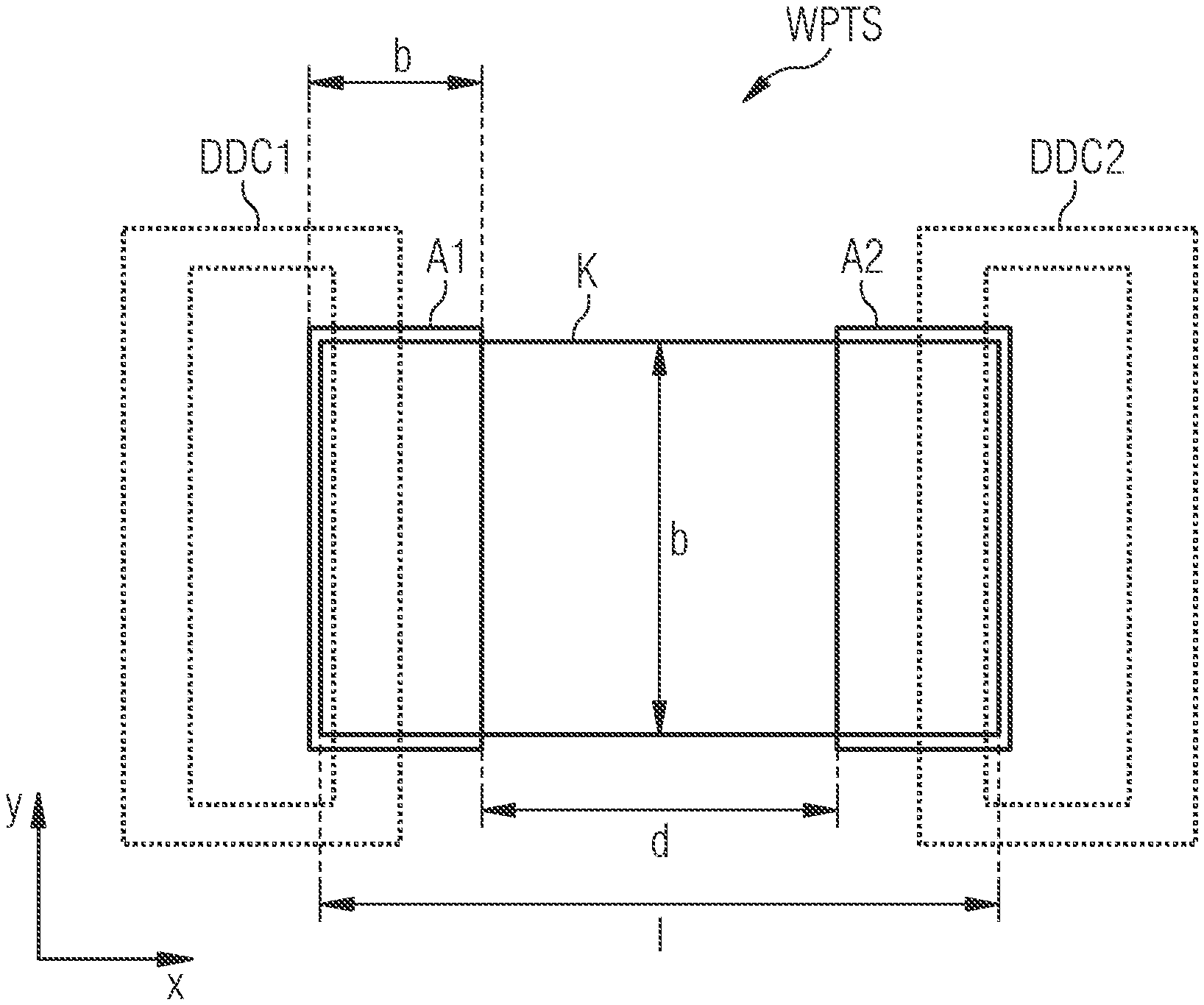
[0034] FIG. 1 shows the relative arrangement of coil core and the portions in plan view.
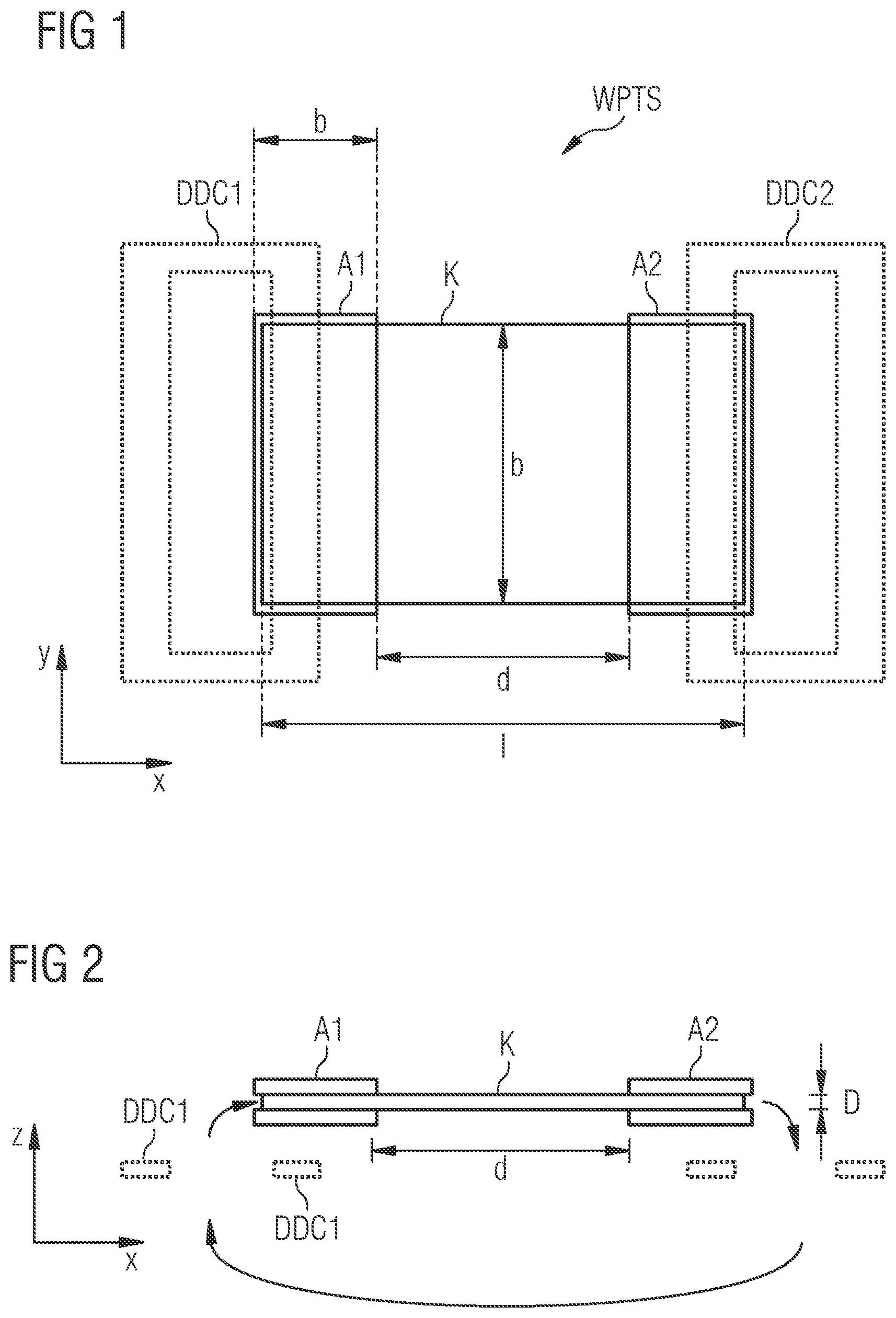
[0035] FIG. 2 shows the arrangement in cross-section.
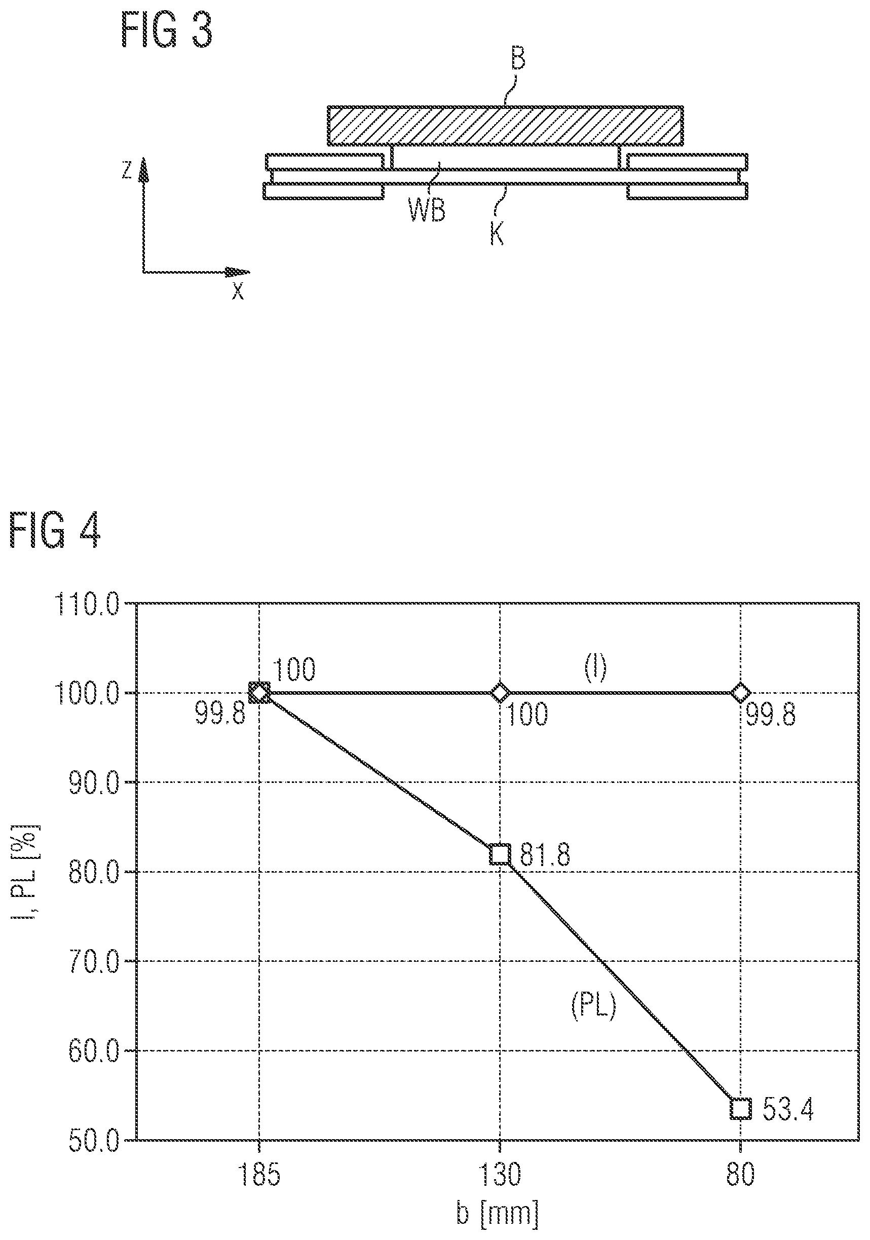
[0036] FIG. 3 shows the use of a thermal bridge.
[0037] FIG. 4 shows the dependency of coil inductance and losses on the extent of a portion in the axial direction.
DETAILED DESCRIPTION
[0038] FIG. 1 shows the arrangement of the two portions A1, A2 of a coil, the winding of which is divided into two portions, in relation to the associated coil core K in plan view. The coil core K has a rectangular base area with a length l in the axial direction x and a width b in the lateral direction y. The two portions A1, A2 of the winding are arranged at the ends of the coil core K which are spaced furthest apart. The portions have a spacing d. FIG. 1 shows a form of the magnet coil with precisely two portions.
[0039] The two portions DDC1, DDC2 of a primary coil in double-D configuration are shown in dashed lines. Coil portions DDC1, DDC2 of the primary coil form, together with the two portions A1, A2 and the coil core K of the magnet coil as secondary coil, the magnetically active components of a wireless electrical power transfer system (WPTS).
[0040] Dividing the winding of the secondary coil into two spaced portions distributes the magnetic flux over a greater volume, specifically in the coil core K, such that the magnetic flux density in the coil core K is reduced. Due to the superproportional dependency of transfer losses on magnetic flux density, power or energy losses on transfer of electrical power are reduced.
[0041] FIG. 2 shows the arrangement of the components of the power transfer system in cross-section. Each of the two portions A1, A2 of the winding of the magnet coil has conductor portions which, viewed in the vertical direction (z), are arranged above the material of the magnet core K, and conductor portions which are arranged below the magnet core K.
[0042] The portions need not terminate flush with the magnet core K in the axial direction (x). It is possible for the portions of the winding to project beyond the respective ends of the coil core (as shown in FIG. 2). It is, however, also possible for the coil core to terminate exactly flush with the portions at the respective ends. It is also possible for the coil core K to project beyond each of the distal ends of the portions A1, A2.
[0043] The arrows substantially illustrate the course of the magnetic field lines at a certain point in time.
[0044] FIG. 3 shows the possibility of using a thermal bridge WB to carry away dissipated power, which accumulates in the form of heat in the coil core K, to external surroundings. The external surroundings may in particular be a mounting base B of a device to which the magnet coil delivers electrical power.
[0045] FIG. 4 shows the dependency of inductance I and power losses PL on the width b of a winding portion of a secondary coil of a wireless power transfer system. While inductance remains substantially constant, power loss falls as width b declines. In other words, dividing a winding of a certain width into two mutually spaced portions each of a smaller width, distinctly reduces power losses.
[0046] The magnet coil is not limited to the technical features shown the figures or described above. The coil may have further conductor portions, for example for electrically interconnecting the portions, switches, electrical terminals for interconnection with an external circuit environment, further elements for guiding magnetic flux or fastening means for contacting.
LIST OF REFERENCE SIGNS
[0047] A1, A2 First and second portions of the magnet coil winding [0048] b Width of the coil core [0049] B Base for dissipating thermal energy [0050] d Spacing of the winding portions [0051] D Thickness of the coil core [0052] DDC1, DDC2 Coil portions of a primary coil [0053] I Inductance [0054] K Coil core [0055] Length of the coil core [0056] PL Power loss [0057] WB Thermal bridge [0058] WPTS Wireless power transfer system [0059] x Axial direction [0060] y Transverse direction [0061] z Vertical direction
* * * * *
D00000
D00001
D00002
XML
uspto.report is an independent third-party trademark research tool that is not affiliated, endorsed, or sponsored by the United States Patent and Trademark Office (USPTO) or any other governmental organization. The information provided by uspto.report is based on publicly available data at the time of writing and is intended for informational purposes only.
While we strive to provide accurate and up-to-date information, we do not guarantee the accuracy, completeness, reliability, or suitability of the information displayed on this site. The use of this site is at your own risk. Any reliance you place on such information is therefore strictly at your own risk.
All official trademark data, including owner information, should be verified by visiting the official USPTO website at www.uspto.gov. This site is not intended to replace professional legal advice and should not be used as a substitute for consulting with a legal professional who is knowledgeable about trademark law.