Optical Imaging Lens Group
JI; Yunbing ; et al.
U.S. patent application number 17/123663 was filed with the patent office on 2021-04-08 for optical imaging lens group. This patent application is currently assigned to ZHEJIANG SUNNY OPTICS CO., LTD.. The applicant listed for this patent is ZHEJIANG SUNNY OPTICS CO., LTD.. Invention is credited to Yunbing JI, Yu TANG, Xin ZHOU.
| Application Number | 20210103129 17/123663 |
| Document ID | / |
| Family ID | 1000005291684 |
| Filed Date | 2021-04-08 |


View All Diagrams
| United States Patent Application | 20210103129 |
| Kind Code | A1 |
| JI; Yunbing ; et al. | April 8, 2021 |
OPTICAL IMAGING LENS GROUP
Abstract
The present disclosure discloses an optical imaging lens group including, sequentially from an object side to an image side along an optical axis, a first lens, a second lens, a third lens, a fourth lens, a fifth lens, a sixth lens, a seventh lens and an eighth lens. The first lens has positive refractive power, a convex object-side surface and a concave image-side surface; the second lens has negative refractive power and a concave image-side surface; the third lens has positive refractive power and a convex object-side surface; the fourth lens has refractive power; the fifth lens has refractive power; the sixth lens has refractive power, a convex object-side surface and a concave image-side surface; the seventh lens has positive refractive power; and the eighth lens has refractive power. A total effective focal length f and an entrance pupil diameter EPD satisfy f/EPD<1.4.
| Inventors: | JI; Yunbing; (Yuyao Zhejiang, CN) ; ZHOU; Xin; (Yuyao Zhejiang, CN) ; TANG; Yu; (Yuyao Zhejiang, CN) | ||||||||||
| Applicant: |
|
||||||||||
|---|---|---|---|---|---|---|---|---|---|---|---|
| Assignee: | ZHEJIANG SUNNY OPTICS CO.,
LTD. Yuyao Zhejiang CN |
||||||||||
| Family ID: | 1000005291684 | ||||||||||
| Appl. No.: | 17/123663 | ||||||||||
| Filed: | December 16, 2020 |
Related U.S. Patent Documents
| Application Number | Filing Date | Patent Number | ||
|---|---|---|---|---|
| PCT/CN2019/102144 | Aug 23, 2019 | |||
| 17123663 | ||||
| Current U.S. Class: | 1/1 |
| Current CPC Class: | G02B 13/0045 20130101; G02B 9/64 20130101 |
| International Class: | G02B 13/00 20060101 G02B013/00; G02B 9/64 20060101 G02B009/64 |
Foreign Application Data
| Date | Code | Application Number |
|---|---|---|
| Nov 27, 2018 | CN | 201811424454.6 |
Claims
1. An optical imaging lens group, comprising, sequentially from an object side to an image side along an optical axis, a first lens, a second lens, a third lens, a fourth lens, a fifth lens, a sixth lens, a seventh lens and an eighth lens, wherein, the first lens has positive refractive power, a convex object-side surface and a concave image-side surface; the second lens has negative refractive power and a concave image-side surface; the third lens has positive refractive power and a convex object-side surface; the fourth lens has refractive power; the fifth lens has refractive power; the sixth lens has refractive power, a convex object-side surface and a concave image-side surface; the seventh lens has positive refractive power; and the eighth lens has refractive power, wherein f/EPD<1.4, where f is a total effective focal length of the optical imaging lens group, and EPD is an entrance pupil diameter of the optical imaging lens group.
2. The optical imaging lens group according to claim 1, wherein 1<f1/ImgH<2, where f1 is an effective focal length of the first lens, and ImgH is half of a diagonal length of an effective pixel area on an imaging plane of the optical imaging lens group.
3. The optical imaging lens group according to claim 1, wherein 0.1<R1/R2<0.5, where R1 is a radius of curvature of the object-side surface of the first lens, and R2 is a radius of curvature of the image-side surface of the first lens.
4. The optical imaging lens group according to claim 1, wherein -1.5<f2/f3<-0.5, where f2 is an effective focal length of the second lens, and f3 is an effective focal length of the third lens.
5. The optical imaging lens group according to claim 1, wherein 1<TTL/R5<3, where TTL is a distance along the optical axis from the object-side surface of the first lens to an imaging plane of the optical imaging lens group, and R5 is a radius of curvature of the object-side surface of the third lens.
6. The optical imaging lens group according to claim 1, wherein 1<R11/R12<1.5, where R11 is a radius of curvature of the object-side surface of the sixth lens, and R12 is a radius of curvature of the image-side surface of the sixth lens.
7. The optical imaging lens group according to claim 1, wherein 1<CT1/(CT4+CT5)<2, where CT1 is a center thickness of the first lens along the optical axis, CT4 is a center thickness of the fourth lens along the optical axis, and CT5 is a center thickness of the fifth lens along the optical axis.
8. The optical imaging lens group according to claim 1, wherein 1<CT7/CT8<2, where CT7 is a center thickness of the seventh lens along the optical axis, and CT8 is a center thickness of the eighth lens along the optical axis.
9. The optical imaging lens group according to claim 1, wherein -4<f456/f123<-1.5, where f123 is a combined focal length of the first lens, the second lens and the third lens, and f456 is a combined focal length of the fourth lens, the fifth lens and the sixth lens.
10. The optical imaging lens group according to claim 1, wherein 2<.SIGMA.CT/.SIGMA.AT<2.5, where .SIGMA.CT is a sum of center thicknesses of the first lens to the eighth lens along the optical axis, and .SIGMA.AT is a sum of spaced intervals along the optical axis between each two adjacent lenses of the first lens to the eighth lens.
11. An optical imaging lens group, comprising, sequentially from an object side to an image side along an optical axis, a first lens, a second lens, a third lens, a fourth lens, a fifth lens, a sixth lens, a seventh lens and an eighth lens, wherein, the first lens has positive refractive power, a convex object-side surface and a concave image-side surface; the second lens has negative refractive power and a concave image-side surface; the third lens has positive refractive power and a convex object-side surface; the fourth lens has refractive power; the fifth lens has refractive power; the sixth lens has refractive power, a convex object-side surface and a concave image-side surface; the seventh lens has positive refractive power; and the eighth lens has refractive power, wherein -4<f456/f123<-1.5, where f123 is a combined focal length of the first lens, the second lens and the third lens, and f456 is a combined focal length of the fourth lens, the fifth lens and the sixth lens.
12. The optical imaging lens group according to claim 11, wherein 1<f1/ImgH<2, where f1 is an effective focal length of the first lens, and ImgH is half of a diagonal length of an effective pixel area on an imaging plane of the optical imaging lens group.
13. The optical imaging lens group according to claim 12, wherein f/EPD<1.4, where f is a total effective focal length of the optical imaging lens group, and EPD is an entrance pupil diameter of the optical imaging lens group.
14. The optical imaging lens group according to claim 11, wherein 0.1<R1/R2<0.5, where R1 is a radius of curvature of the object-side surface of the first lens, and R2 is a radius of curvature of the image-side surface of the first lens.
15. The optical imaging lens group according to claim 11, wherein -1.5<f2/f3<-0.5, where f2 is an effective focal length of the second lens, and f3 is an effective focal length of the third lens.
16. The optical imaging lens group according to claim 11, wherein 1<R11/R12<1.5, where R11 is a radius of curvature of the object-side surface of the sixth lens, and R12 is a radius of curvature of the image-side surface of the sixth lens.
17. The optical imaging lens group according to claim 11, wherein 2<.SIGMA.CT/.SIGMA.AT<2.5, where .SIGMA.CT is a sum of center thicknesses of the first lens to the eighth lens along the optical axis, and .SIGMA.AT is a sum of spaced intervals along the optical axis between each two adjacent lenses of the first lens to the eighth lens.
18. The optical imaging lens group according to claim 17, wherein 1<CT1/(CT4+CT5)<2, where CT1 is a center thickness of the first lens along the optical axis, CT4 is a center thickness of the fourth lens along the optical axis, and CT5 is a center thickness of the fifth lens along the optical axis.
19. The optical imaging lens group according to claim 17, wherein 1<CT7/CT8<2, where CT7 is a center thickness of the seventh lens along the optical axis, and CT8 is a center thickness of the eighth lens along the optical axis.
20. The optical imaging lens group according to claim 11, wherein 1<TTL/R5<3, where TTL is a distance along the optical axis from the object-side surface of the first lens to an imaging plane of the optical imaging lens group, and R5 is a radius of curvature of the object-side surface of the third lens.
Description
CROSS-REFERENCE TO RELATED APPLICATION
[0001] The present patent application is a continuation of International Application No. PCT/CN2019/102144, filed on Aug. 23, 2019, which claims priority to Chinese Patent Application No. 201811424454.6, filed before the China National Intellectual Property Administration (CNIPA) on Nov. 27, 2018. All of the aforementioned patent applications are hereby incorporated by reference in their entireties.
TECHNICAL FIELD
[0002] The present disclosure relates to an optical imaging lens group, and more specifically, relates to an optical imaging lens group including eight lenses.
BACKGROUND
[0003] At present, in order to meet the requirements of multiple application scenarios, different types of optical imaging lens groups have gradually appeared on the market. For example, the telephoto optical lens group is suitable for long-distance imaging, the ultra-thin optical lens group is suitable for ultra-thin mobile phone bodies, the ultra-wide-angle optical lens group is suitable for wide-angle imaging and is used in ball screen projection, vehicle security, etc., and the large-aperture optical lens group is suitable for clear imaging in low light conditions. The large-aperture optical imaging lens group has the following advantages: it helps to clear imaging in dim light; and it helps to obtain a small depth of field to achieve a shooting effect with a large aperture background blur. These advantages make the large-aperture optical imaging lens group more popular in the field of mobile phone camera.
[0004] Due to the large aperture of the large-aperture imaging lens group, the lens aperture and the total length of the lens group tend to be relatively large. Conventional systems using spherical lenses are difficult to achieve large-aperture imaging while ensuring a small lens aperture and short total lens group length. Therefore, how to improve the imaging clarity of the large-aperture imaging lens group while satisfying the miniaturization of the system is one of the most important issues in this field.
SUMMARY
[0005] The present disclosure provides an optical imaging lens group that is applicable to portable electronic products and at least solves or partially solves at least one of the above disadvantages of the prior art.
[0006] In one aspect, the present disclosure provides an optical imaging lens group which includes, sequentially from an object side to an image side along an optical axis, a first lens, a second lens, a third lens, a fourth lens, a fifth lens, a sixth lens, a seventh lens and an eighth lens. The first lens may have positive refractive power, an object-side surface thereof may be convex, and an image-side surface thereof may be concave; the second lens may have negative refractive power, and an image-side surface thereof may be concave; the third lens may have positive refractive power, and an object-side surface thereof may be convex; the fourth lens has positive or negative refractive power; the fifth lens has positive or negative refractive power; the sixth lens has positive or negative refractive power, an object-side surface thereof may be convex, and an image-side surface thereof may be concave; the seventh lens may have positive refractive power; and the eighth lens has positive or negative refractive power.
[0007] In one embodiment, a total effective focal length f of the optical imaging lens group and an entrance pupil diameter EPD of the optical imaging lens group may satisfy f/EPD<1.4.
[0008] In one embodiment, an effective focal length f1 of the first lens and half of a diagonal length ImgH of an effective pixel area on an imaging plane of the optical imaging lens group may satisfy 1<f1/ImgH<2.
[0009] In one embodiment, a radius of curvature R1 of the object-side surface of the first lens and a radius of curvature R2 of the image-side surface of the first lens may satisfy 0.1<R1/R2<0.5.
[0010] In one embodiment, an effective focal length f2 of the second lens and an effective focal length f3 of the third lens may satisfy -1.5<f2/f3<-0.5.
[0011] In one embodiment, a distance TTL along the optical axis from the object-side surface of the first lens to an imaging plane of the optical imaging lens group and a radius of curvature R5 of the object-side surface of the third lens may satisfy 1<TTL/R5<3.
[0012] In one embodiment, a radius of curvature R11 of the object-side surface of the sixth lens and a radius of curvature R12 of the image-side surface of the sixth lens may satisfy 1<R11/R12<1.5.
[0013] In one embodiment, a center thickness CT1 of the first lens along the optical axis, a center thickness CT4 of the fourth lens along the optical axis and a center thickness CT5 of the fifth lens along the optical axis may satisfy 1<CT1/(CT4+CT5)<2.
[0014] In one embodiment, a center thickness CT7 of the seventh lens along the optical axis and a center thickness CT8 of the eighth lens along the optical axis may satisfy 1<CT7/CT8<2.
[0015] In one embodiment, a combined focal length f123 of the first lens, the second lens and the third lens and a combined focal length f456 of the fourth lens, the fifth lens and the sixth lens may satisfy -4<f456/f123<-1.5.
[0016] In one embodiment, a sum of center thicknesses .SIGMA.CT of the first lens to the eighth lens along the optical axis and a sum of spaced intervals .SIGMA.AT along the optical axis between each two adjacent lenses of the first lens to the eighth lens may satisfy 2<.SIGMA.CT/.SIGMA.AT<2.5.
[0017] The present disclosure employs eight lenses, and the optical imaging lens group has at least one beneficial effect, such as large aperture, miniaturization and high image quality and the like, by rationally configuring the refractive power, the surface shape, the center thickness of each lens, and the on-axis spaced interval between the lenses and the like.
BRIEF DESCRIPTION OF THE DRAWINGS
[0018] Other features, objects, and advantages of the present disclosure will become more apparent from the following detailed description of the non-limiting embodiments with reference to the accompanying drawings. In the drawings:
[0019] FIG. 1 illustrates a schematic structural view of an optical imaging lens group according to example 1 of the present disclosure; and FIGS. 2A to 2D illustrate a longitudinal aberration curve, an astigmatic curve, a distortion curve, and a lateral color curve of the optical imaging lens group of the example 1, respectively.
[0020] FIG. 3 illustrates a schematic structural view of an optical imaging lens group according to example 2 of the present disclosure; and FIGS. 4A to 4D illustrate a longitudinal aberration curve, an astigmatic curve, a distortion curve, and a lateral color curve of the optical imaging lens group of the example 2, respectively.
[0021] FIG. 5 illustrates a schematic structural view of an optical imaging lens group according to example 3 of the present disclosure; and FIGS. 6A to 6D illustrate a longitudinal aberration curve, an astigmatic curve, a distortion curve, and a lateral color curve of the optical imaging lens group of the example 3, respectively.
[0022] FIG. 7 illustrates a schematic structural view of an optical imaging lens group according to example 4 of the present disclosure; and FIGS. 8A to 8D illustrate a longitudinal aberration curve, an astigmatic curve, a distortion curve, and a lateral color curve of the optical imaging lens group of the example 4, respectively.
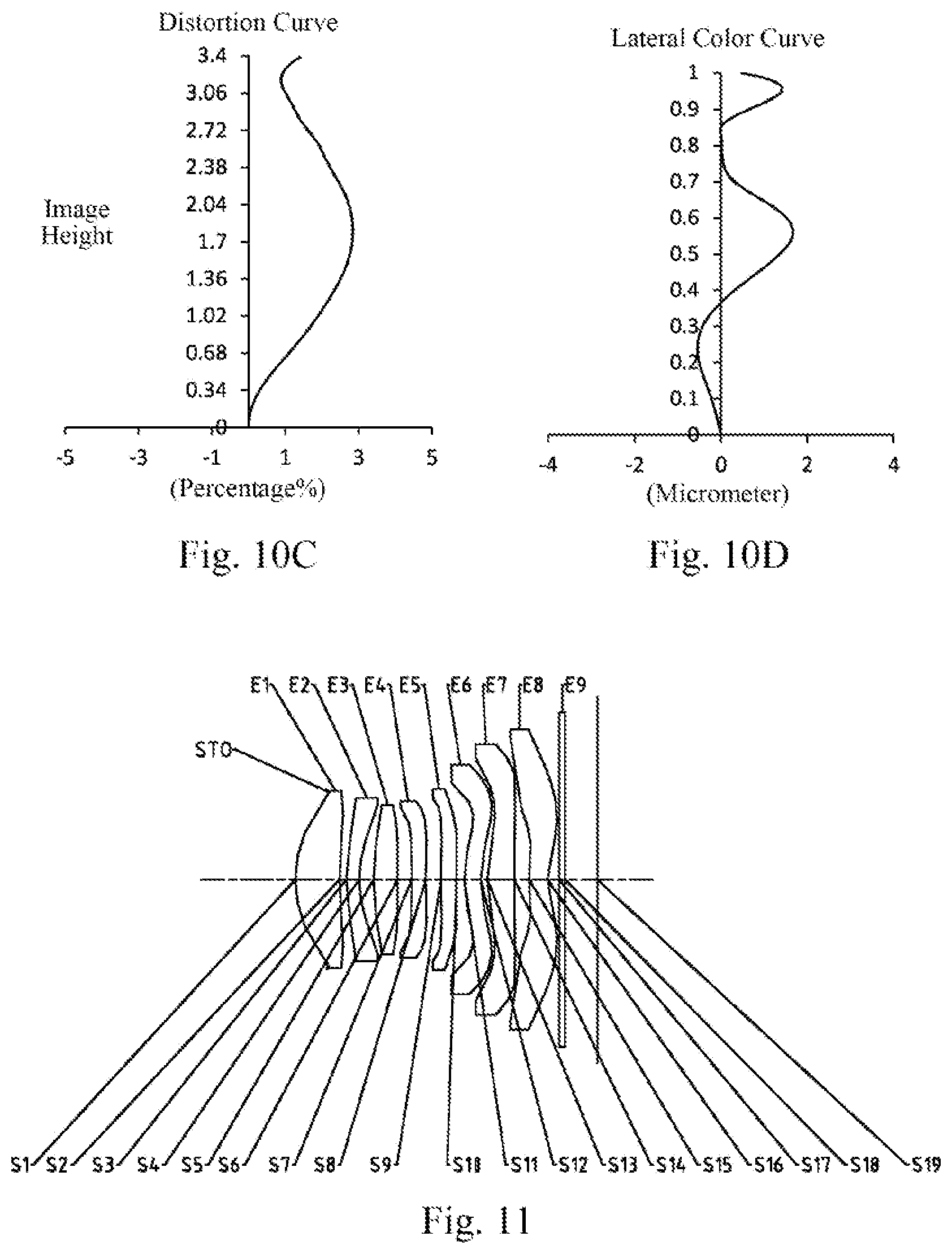
[0023] FIG. 9 illustrates a schematic structural view of an optical imaging lens group according to example 5 of the present disclosure; and FIGS. 10A to 10D illustrate a longitudinal aberration curve, an astigmatic curve, a distortion curve, and a lateral color curve of the optical imaging lens group of the example 5, respectively.
[0024] FIG. 11 illustrates a schematic structural view of an optical imaging lens group according to example 6 of the present disclosure; and FIGS. 12A to 12D illustrate a longitudinal aberration curve, an astigmatic curve, a distortion curve, and a lateral color curve of the optical imaging lens group of the example 6, respectively.
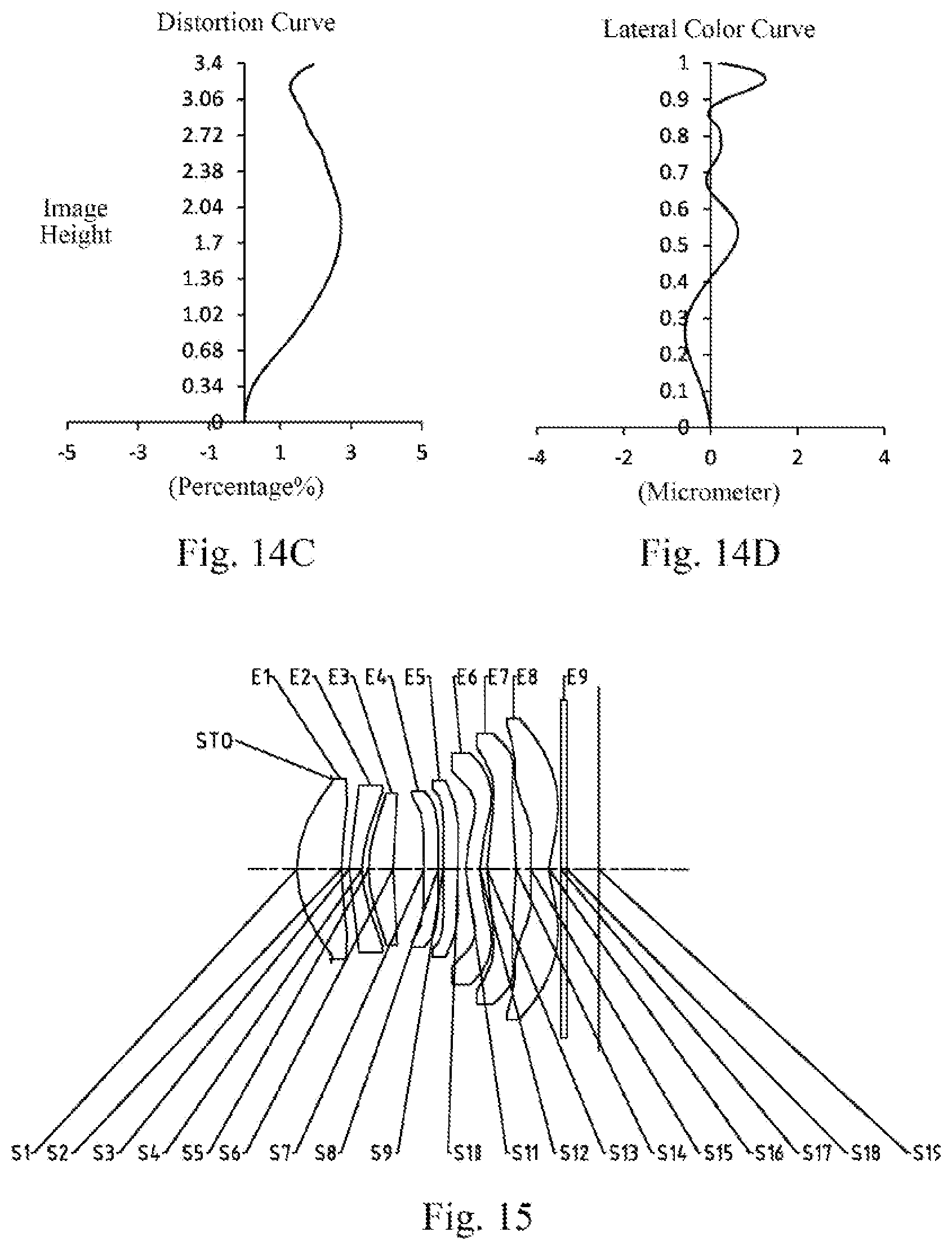
[0025] FIG. 13 illustrates a schematic structural view of an optical imaging lens group according to example 7 of the present disclosure; and FIGS. 14A to 14D illustrate a longitudinal aberration curve, an astigmatic curve, a distortion curve, and a lateral color curve of the optical imaging lens group of the example 7, respectively.
[0026] FIG. 15 illustrates a schematic structural view of an optical imaging lens group according to example 8 of the present disclosure; and FIGS. 16A to 16D illustrate a longitudinal aberration curve, an astigmatic curve, a distortion curve, and a lateral color curve of the optical imaging lens group of the example 8, respectively.
[0027] FIG. 17 illustrates a schematic structural view of an optical imaging lens group according to example 9 of the present disclosure; and FIGS. 18A to 18D illustrate a longitudinal aberration curve, an astigmatic curve, a distortion curve, and a lateral color curve of the optical imaging lens group of the example 9, respectively.
[0028] FIG. 19 illustrates a schematic structural view of an optical imaging lens group according to example 10 of the present disclosure; and FIGS. 20A to 20D illustrate a longitudinal aberration curve, an astigmatic curve, a distortion curve, and a lateral color curve of the optical imaging lens group of the example 10, respectively.
[0029] FIG. 21 illustrates a schematic structural view of an optical imaging lens group according to example 11 of the present disclosure; and FIGS. 22A to 22D illustrate a longitudinal aberration curve, an astigmatic curve, a distortion curve, and a lateral color curve of the optical imaging lens group of the example 11, respectively.
[0030] FIG. 23 illustrates a schematic structural view of an optical imaging lens group according to example 12 of the present disclosure; and FIGS. 24A to 24D illustrate a longitudinal aberration curve, an astigmatic curve, a distortion curve, and a lateral color curve of the optical imaging lens group of the example 12, respectively.
DETAILED DESCRIPTION OF EMBODIMENTS
[0031] For a better understanding of the present disclosure, various aspects of the present disclosure will be described in more detail with reference to the accompanying drawings. It should be understood that the detailed description is merely illustrative of the exemplary embodiments of the present disclosure and is not intended to limit the scope of the present disclosure in any way. Throughout the specification, the same reference numerals refer to the same elements. The expression "and/or" includes any and all combinations of one or more of the associated listed items.
[0032] It should be noted that in the present specification, the expressions such as first, second, third are used merely for distinguishing one feature from another, without indicating any limitation on the features. Thus, a first lens discussed below may also be referred to as a second lens or a third lens without departing from the teachings of the present disclosure.
[0033] In the accompanying drawings, the thickness, size and shape of the lens have been somewhat exaggerated for the convenience of explanation. In particular, shapes of spherical surfaces or aspheric surfaces shown in the accompanying drawings are shown by way of example. That is, shapes of the spherical surfaces or the aspheric surfaces are not limited to the shapes of the spherical surfaces or the aspheric surfaces shown in the accompanying drawings. The accompanying drawings are merely illustrative and not strictly drawn to scale.
[0034] Herein, the paraxial area refers to an area near the optical axis. If a surface of a lens is convex and the position of the convex is not defined, it indicates that the surface of the lens is convex at least in the paraxial region; and if a surface of a lens is concave and the position of the concave is not defined, it indicates that the surface of the lens is concave at least in the paraxial region. In each lens, the surface closest to the object is referred to as an object-side surface of the lens, and the surface closest to the imaging plane is referred to as an image-side surface of the lens.
[0035] It should be further understood that the terms "comprising," "including," "having," "containing" and/or "contain," when used in the specification, specify the presence of stated features, elements and/or components, but do not exclude the presence or addition of one or more other features, elements, components and/or combinations thereof. In addition, expressions, such as "at least one of," when preceding a list of features, modify the entire list of features rather than an individual element in the list. Further, the use of "may," when describing embodiments of the present disclosure, refers to "one or more embodiments of the present disclosure." Also, the term "exemplary" is intended to refer to an example or illustration.
[0036] Unless otherwise defined, all terms (including technical and scientific terms) used herein have the same meaning as commonly understood by those of ordinary skill in the art to which the present disclosure belongs. It will be further understood that terms, such as those defined in commonly used dictionaries, should be interpreted as having a meaning that is consistent with the meaning in the context of the relevant art and will not be interpreted in an idealized or overly formal sense, unless expressly so defined herein.
[0037] It should also be noted that, the examples in the present disclosure and the features in the examples may be combined with each other on a non-conflict basis. The present disclosure will be described in detail below with reference to the accompanying drawings and in combination with the examples. The features, principles, and other aspects of the present disclosure are described in detail below.
[0038] An optical imaging lens group according to an exemplary embodiment of the present disclosure may include, for example, eight lenses having refractive power, which are a first lens, a second lens, a third lens, a fourth lens, a fifth lens, a sixth lens, a seventh lens and an eighth lens. The eight lenses are arranged sequentially from an object side to an image side along an optical axis. Among the first lens to the eighth lens, there may be an air interval between each two adjacent lenses.
[0039] In an exemplary embodiment, the first lens may have positive refractive power, an object-side surface thereof may be convex, and an image-side surface thereof may be concave; the second lens may have negative refractive power, and an image-side surface thereof may be concave; the third lens may have positive refractive power, and an object-side surface thereof may be convex; the fourth lens has positive or negative refractive power; the fifth lens has positive or negative refractive power; the sixth lens has positive or negative refractive power, an object-side surface thereof may be convex, and an image-side surface thereof may be concave; the seventh lens may have positive refractive power; and the eighth lens has positive or negative refractive power.
[0040] In an exemplary embodiment, an image-side surface of the fifth lens may be concave.
[0041] In an exemplary embodiment, an object-side surface of the seventh lens may be convex.
[0042] In an exemplary embodiment, an image-side surface of the eighth lens may be concave.
[0043] In an exemplary embodiment, the optical imaging lens group according to the present disclosure may satisfy: f/EPD<1.4, where f is a total effective focal length of the optical imaging lens group, and EPD is an entrance pupil diameter of the optical imaging lens group. More specifically, f and EPD may further satisfy: 1.1<f/EPD<1.4, for example, 1.29.ltoreq.f/EPD.ltoreq.1.36. Satisfying the conditional expression f/EPD<1.4 is conducive to realizing large-aperture imaging to facilitate clear imaging under low-light conditions.
[0044] In an exemplary embodiment, the optical imaging lens group according to the present disclosure may satisfy: 1<f1/ImgH<2, where f1 is an effective focal length of the first lens, and ImgH is half of a diagonal length of an effective pixel area on an imaging plane of the optical imaging lens group. More specifically, f1 and ImgH may further satisfy: 1.3<f1/ImgH<1.9, for example, 1.45.ltoreq.f1/ImgH.ltoreq.1.86. When the conditional expression 1<f1/ImgH<2 is satisfied, the image height may be effectively prevented from being too small, which is beneficial to matching the chip. At the same time, it is beneficial to improve the chromatic aberration and distortion of the system.
[0045] In an exemplary embodiment, the optical imaging lens group according to the present disclosure may satisfy: -1.5<f2/f3<-0.5, where f2 is an effective focal length of the second lens, and f3 is an effective focal length of the third lens. More specifically, f2 and f3 may further satisfy: -1.33.ltoreq.f2/f3.ltoreq.-0.88. By reasonably assigning the refractive power of the second lens and the third lens, it is beneficial to compensate the chromatic aberration and effectively reduce the total length of the system. Meanwhile, it is beneficial to enlarge the aperture.
[0046] In an exemplary embodiment, the optical imaging lens group according to the present disclosure may satisfy: 0.1<R1/R2<0.5, where R1 is a radius of curvature of the object-side surface of the first lens, and R2 is a radius of curvature of the image-side surface of the first lens. More specifically, R1 and R2 may further satisfy: 0.17.ltoreq.R1/R2 .ltoreq.0.43. When the conditional expression 0.1<R1/R2<0.5 is satisfied, the first lens may be effectively prevented from being too curved, which is beneficial to controlling the edge thickness of the first lens and reducing the processing difficulty. At the same time, it is beneficial to improve the chromatic aberration of the optical imaging lens group.
[0047] In an exemplary embodiment, the optical imaging lens group according to the present disclosure may satisfy: 1<TTL/R5<3, where TTL is a distance along the optical axis from the object-side surface of the first lens to an imaging plane of the optical imaging lens group, and R5 is a radius of curvature of the object-side surface of the third lens. More specifically, TTL and R5 may further satisfy: 1.1<TTL/R5<2.7, for example, 1.25.ltoreq.TTL/R5.ltoreq.2.54. Satisfying the conditional expression 1<TTL/R5<3 may effectively prevent the third lens from being too curved, which is beneficial to reducing the difficulty of processing. At the same time, it is beneficial to reasonably control the total length of the system.
[0048] In an exemplary embodiment, the optical imaging lens group according to the present disclosure may satisfy: -4<f456/f123<-1.5, where f123 is a combined focal length of the first lens, the second lens and the third lens, and f456 is a combined focal length of the fourth lens, the fifth lens and the sixth lens. More specifically, f456 and f123 may further satisfy: -3.70.ltoreq.f456/f123.ltoreq.-1.95. When the conditional expression -4 <f456/f123<-1.5 is satisfied, the first, second, and third lenses assume the main refractive power, and cooperate with the fourth, fifth and sixth lenses to compensate the chromatic aberration of the lens group, thereby improving the picture clarity.
[0049] In an exemplary embodiment, the optical imaging lens group according to the present disclosure may satisfy: 1<R11/R12<1.5, where R11 is a radius of curvature of the object-side surface of the sixth lens, and R12 is a radius of curvature of the image-side surface of the sixth lens. More specifically, R11 and R12 may further satisfy: 1.03.ltoreq.R11/R12.ltoreq.1.37. Satisfying the conditional expression 1<R11/R12<1.5 may effectively prevent the sixth lens from being too curved, which is beneficial to reducing the processing difficulty and effectively controlling the chromatic aberration and field curvature of the system.
[0050] In an exemplary embodiment, the optical imaging lens group according to the present disclosure may satisfy: 2<.SIGMA.CT/.SIGMA.AT<2.5, where .SIGMA.CT is a sum of center thicknesses of the first lens to the eighth lens along the optical axis, and .SIGMA.AT is a sum of spaced intervals along the optical axis between each two adjacent lenses of the first lens to the eighth lens. More specifically, .SIGMA.CT and .SIGMA.AT may further satisfy: 2.01.ltoreq..SIGMA.CT/.SIGMA.AT .ltoreq.2.34. When the conditional expression 2<.SIGMA.CT/.SIGMA.AT<2.5 is satisfied, it is beneficial to control the air interval between adjacent lenses and the total length of the system, thereby reducing the difficulty of processing and assembly. At the same time, it is beneficial to provide sufficient space between adjacent lenses so that the surface of each lens has a higher degree of freedom to change, so as to improve the ability of the optical imaging lens group to correct astigmatic and field curvature.
[0051] In an exemplary embodiment, the optical imaging lens group according to the present disclosure may satisfy: 1<CT1/(CT4+CT5)<2, where CT1 is a center thickness of the first lens along the optical axis, CT4 is a center thickness of the fourth lens along the optical axis, and CT5 is a center thickness of the fifth lens along the optical axis. More specifically, CT1, CT4 and CT5 may further satisfy: 1.3<CT1/(CT4+CT5)<1.7, for example, 1.42.ltoreq.CT1/(CT4+CT5).ltoreq.1.58. Satisfying the conditional expression 1<CT1/(CT4+CT5)<2 may effectively prevent the center thicknesses of the fourth lens and the fifth lens from being too thin, thereby reducing the difficulty of processing and assembly.
[0052] In an exemplary embodiment, the optical imaging lens group according to the present disclosure may satisfy: 1<CT7/CT8<2, where CT7 is a center thickness of the seventh lens along the optical axis, and CT8 is a center thickness of the eighth lens along the optical axis. More specifically, CT7 and CT8 may further satisfy: 1.10.ltoreq.CT7/CT8.ltoreq.1.60. Satisfying the conditional expression 1<CT7/CT8<2 may effectively avoid the excessive difference in the center thickness of the seventh lens and the eighth lens, thereby reducing the difficulty of assembly and ensuring the shape of the lens's surface. At the same time, it may effectively correct the field curvature.
[0053] In an exemplary embodiment, the above optical imaging lens group may further include a stop to improve the image quality of the optical imaging lens group. Optionally, the stop may be disposed between the object side and the first lens. Optionally, the above optical imaging lens group may further include an optical filter for correcting the color deviation and/or a protective glass for protecting the photosensitive element located on an imaging plane.
[0054] The optical imaging lens group according to the above embodiments of the present disclosure may employ a plurality of lenses, such as eight lenses as described above. By properly configuring the refractive power of each lens, the surface shape, the center thickness of each lens, and spaced intervals along the optical axis between the lenses, the size and the sensitivity of the optical imaging lens group may be effectively reduced, and the workability of the optical imaging lens group may be improved, such that the optical imaging lens group is more advantageous for production processing and may be applied to portable electronic products. The optical imaging lens group configured as described above may also have beneficial effects such as large aperture, miniaturization, high image quality, and the like.
[0055] In the embodiments of the present disclosure, at least one of the surfaces of the lenses is aspheric, that is, at least one of the object-side surface and the image-side surface of each of the first lens, the second lens, the third lens, the fourth lens, the fifth lens, the sixth lens, the seventh lens and the eighth lens is aspheric. The aspheric lens is characterized by a continuous change in curvature from the center of the lens to the periphery of the lens. Unlike a spherical lens having a constant curvature from the center of the lens to the periphery of the lens, the aspheric lens has a better curvature radius characteristic, and has the advantages of improving distortion aberration and improving astigmatic aberration. With aspheric lens, the aberrations that occur during imaging may be eliminated as much as possible, and thus improving the image quality. Optionally, the object-side surface and the image-side surface of each of the first lens, the second lens, the third lens, the fourth lens, the fifth lens, the sixth lens, the seventh lens and the eighth lens are aspheric.
[0056] However, it will be understood by those skilled in the art that the number of lenses constituting the optical imaging lens group may be varied to achieve the various results and advantages described in this specification without departing from the technical solution claimed by the present disclosure. For example, although the embodiment is described by taking eight lenses as an example, the optical imaging lens group is not limited to include eight lenses. The optical imaging lens group may also include other numbers of lenses if desired.
[0057] Some specific examples of an optical imaging lens group applicable to the above embodiment will be further described below with reference to the accompanying drawings.
EXAMPLE 1
[0058] An optical imaging lens group according to example 1 of the present disclosure is described below with reference to FIG. 1 to FIG. 2D. FIG. 1 shows a schematic structural view of the optical imaging lens group according to example 1 of the present disclosure.
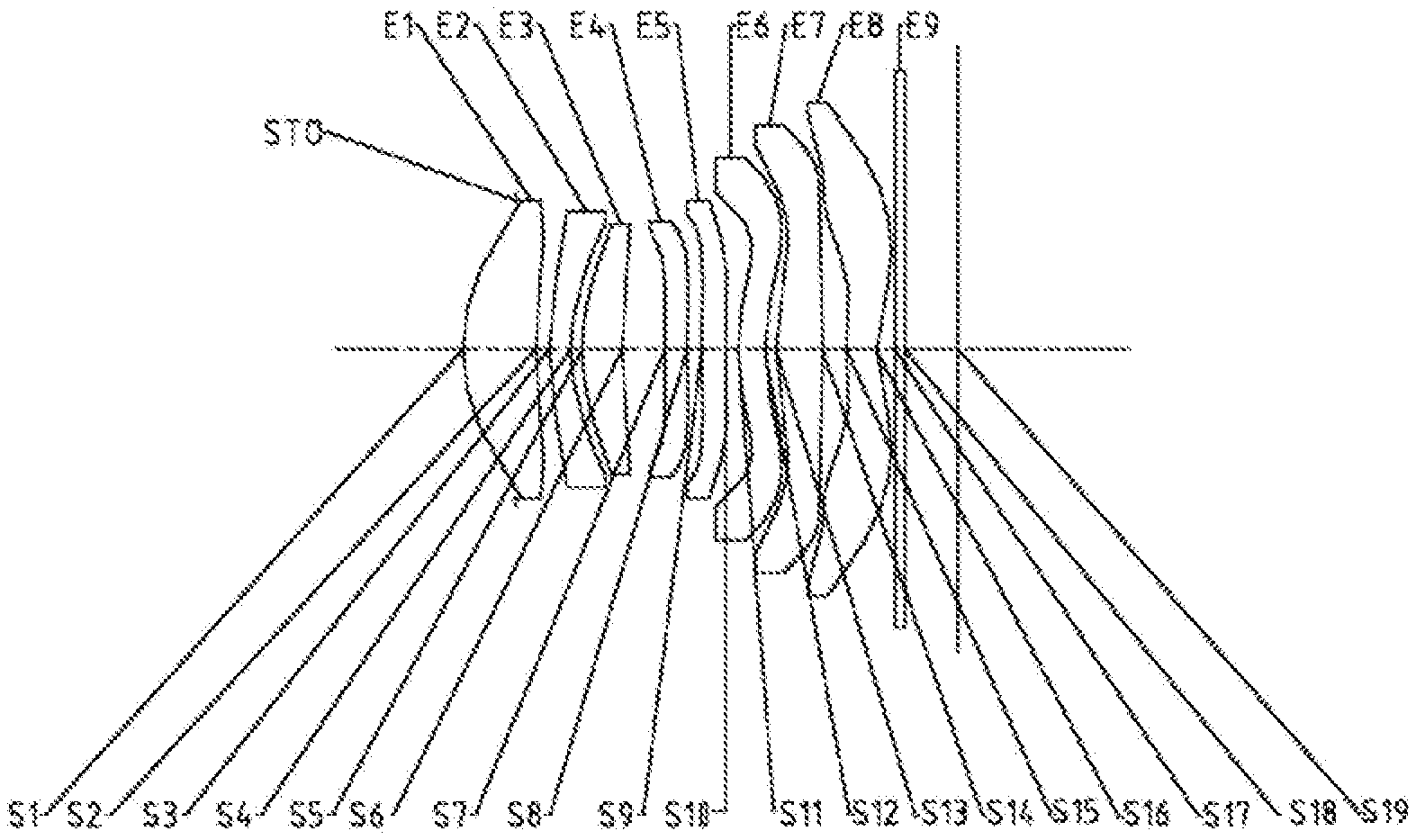
[0059] As shown in FIG. 1, the optical imaging lens group according to an exemplary embodiment of the present disclosure includes a stop STO, a first lens E1, a second lens E2, a third lens E3, a fourth lens E4, a fifth lens E5, a sixth lens E6, a seventh lens E7, an eighth lens E8, an optical filter E9 and an imaging plane S19, which are sequentially arranged from an object side to an image side along an optical axis.
[0060] The first lens E1 has positive refractive power, an object-side surface S1 thereof is convex, and an image-side surface S2 thereof is concave. The second lens E2 has negative refractive power, an object-side surface S3 thereof is convex, and an image-side surface S4 thereof is concave. The third lens E3 has positive refractive power, an object-side surface S5 thereof is convex, and an image-side surface S6 thereof is concave. The fourth lens E4 has negative refractive power, an object-side surface S7 thereof is convex, and an image-side surface S8 thereof is concave. The fifth lens E5 has negative refractive power, an object-side surface S9 thereof is convex, and an image-side surface S10 thereof is concave. The sixth lens E6 has negative refractive power, an object-side surface S11 thereof is convex, and an image-side surface S12 thereof is concave. The seventh lens E7 has positive refractive power, an object-side surface S13 thereof is convex, and an image-side surface S14 thereof is convex. The eighth lens E8 has negative refractive power, an object-side surface S15 thereof is convex, and an image-side surface S16 thereof is concave. The optical filter E9 has an object-side surface S17 and an image-side surface S18. Light from an object sequentially passes through the respective surfaces S1 to S18 and is finally imaged on the imaging plane S19.
[0061] Table 1 shows surface type, radius of curvature, thickness, material and conic coefficient of each lens of the optical imaging lens group in example 1, wherein the units for the radius of curvature and the thickness are millimeter (mm).
TABLE-US-00001 TABLE 1 Material Surface Surface Radius of Refractive Abbe Conic number type curvature Thickness index number coefficient OBJ Spherical Infinite Infinite STO Spherical Infinite -0.5960 S1 Aspheric 2.1671 0.8200 1.55 64.1 -0.6496 S2 Aspheric 5.6223 0.1499 -38.9687 S3 Aspheric 2.7771 0.2400 1.67 20.4 -40.3487 S4 Aspheric 1.8011 0.1337 -5.3677 S5 Aspheric 2.4771 0.4500 1.55 64.1 -1.9340 S6 Aspheric 6.5909 0.4725 16.3962 S7 Aspheric 16.6604 0.2600 1.67 20.4 99.0000 S8 Aspheric 14.8550 0.1638 82.0679 S9 Aspheric 14.5515 0.2700 1.67 20.4 80.2987 S10 Aspheric 8.7498 0.1396 11.8186 S11 Aspheric 2.7131 0.3000 1.66 21.5 -10.6945 S12 Aspheric 2.2016 0.1253 -15.6319 S13 Aspheric 2.6543 0.5204 1.55 64.1 -1.7110 S14 Aspheric -19.5864 0.2741 -99.0000 S15 Aspheric 2.2844 0.3375 1.55 64.1 -14.7042 S16 Aspheric 1.1531 0.2082 -5.8941 S17 Spherical Infinite 0.1100 1.52 64.1 S18 Spherical Infinite 0.5977 S19 Spherical Infinite
[0062] As can be seen from table 1, the object-side surface and the image-side surface of any one of the first lens E1 to the eighth lens E8 are aspheric. In this example, the surface shape x of each aspheric lens may be defined by using, but not limited to, the following aspheric formula:
x = ch 2 1 + 1 - ( k + 1 ) c 2 h 2 + .SIGMA. Aih i ( 1 ) ##EQU00001##
[0063] Where, x is the sag--the axis-component of the displacement of the surface from the aspheric vertex, when the surface is at height h from the optical axis; c is a paraxial curvature of the aspheric surface, c=1/R (that is, the paraxial curvature c is reciprocal of the radius of curvature R in the above Table 1); k is a conic coefficient (given in the above Table 1); Ai is a correction coefficient for the i-th order of the aspheric surface. Table 2 below shows high-order coefficients A4, A6, A8, A10, Al2, A14, A16, A18 and A20 applicable to each aspheric surface S1 to S16 in example 1.
TABLE-US-00002 TABLE 2 Surface number A4 A6 A8 A10 A12 A14 A16 A18 A20 S1 6.4213E-03 1.3008E-05 4.9128E-03 -1.1643E-02 1.2153E-02 -7.1909E-03 2.4294E-03 -4.4729E-04 3.4511E-05 S2 8.7774E-03 6.0202E-05 -1.4444E-02 3.7880E-03 6.7258E-03 -6.4756E-03 2.5516E-03 -4.9383E-04 3.8333E-05 S3 8.2777E-02 -1.4593E-01 1.1608E-01 -4.8453E-02 -6.4647E-03 2.2134E-02 -1.2207E-02 2.9648E-03 -2.7660E-04 S4 -4.5920E-02 1.8425E-01 -3.8022E-01 4.7485E-01 -3.9404E-01 2.1713E-01 -7.6536E-02 1.6056E-02 -1.5577E-03 S5 -4.5613E-02 1.1863E-01 -1.8279E-01 1.4368E-01 -1.5877E-02 -7.6996E-02 6.4142E-02 -2.0368E-02 2.3409E-03 S6 -1.6257E-02 -2.5846E-02 1.0555E-01 -2.3869E-01 3.2170E-01 -2.7175E-01 1.3603E-01 -3.6411E-02 4.0230E-03 S7 -3.7018E-02 4.5791E-02 -1.9573E-01 3.1769E-01 -3.1358E-01 1.9246E-01 -7.3196E-02 1.6157E-02 -1.5973E-03 S8 -9.6537E-03 -5.2163E-02 1.0348E-01 -2.1140E-01 2.6831E-01 -2.1297E-01 1.0077E-01 -2.5852E-02 2.7712E-03 S9 1.7457E-02 -2.5042E-01 5.4739E-01 -6.7786E-01 5.2336E-01 -2.5577E-01 7.4187E-02 -1.0966E-02 5.4193E-04 S10 7.6114E-02 -5.6227E-01 1.0385E+00 -1.1546E+00 8.3546E-01 -3.9389E-01 1.1588E-01 -1.9167E-02 1.3530E-03 S11 1.3308E-01 -3.6404E-01 4.8443E-01 -4.4906E-01 2.8234E-01 -1.1804E-01 3.0576E-02 -4.3299E-03 2.5230E-04 S12 4.5861E-02 -6.5508E-02 2.3305E-02 3.8136E-03 -7.6739E-03 3.2392E-03 -6.5542E-04 6.5224E-05 -2.5319E-06 S13 -1.2458E-01 1.0231E-01 -6.1589E-02 1.5137E-02 6.9705E-04 -1.1648E-03 2.4519E-04 -2.1296E-05 6.5420E-07 S14 -4.3902E-02 6.2003E-02 -6.4948E-03 -2.5110E-02 1.7034E-02 -5.0966E-03 8.0487E-04 -6.5313E-05 2.1493E-06 S15 -4.1670E-01 3.4042E-01 -1.8074E-01 6.9873E-02 -1.8300E-02 3.0534E-03 -3.0880E-04 1.7270E-05 -4.1101E-07 S16 -2.1132E-01 1.6242E-01 -9.0004E-02 3.4499E-02 -9.1240E-03 1.6204E-03 -1.8187E-04 1.1511E-05 -3.1048E-07
[0064] Table 3 shows half of a diagonal length ImgH of an effective pixel area on the imaging plane S19 of the optical imaging lens group, a total optical length TTL (i.e., a distance from the object-side surface S1 of the first lens E1 to the imaging plane S19 along the optical axis), half of a maximal field-of-view HFOV, a total effective focal length f of the optical imaging lens group, and effective focal lengths f1 to f8 of respective lens in example 1.
TABLE-US-00003 TABLE 3 ImgH (mm) 3.39 f3 (mm) 6.99 TTL (mm) 5.57 f4 (mm) -217.72 HFOV (.degree.) 37.0 f5 (mm) -33.47 f (mm) 4.33 f6 (mm) -23.15 f1 (mm) 5.95 f7 (mm) 4.31 f2 (mm) -8.51 f8 (mm) -4.76
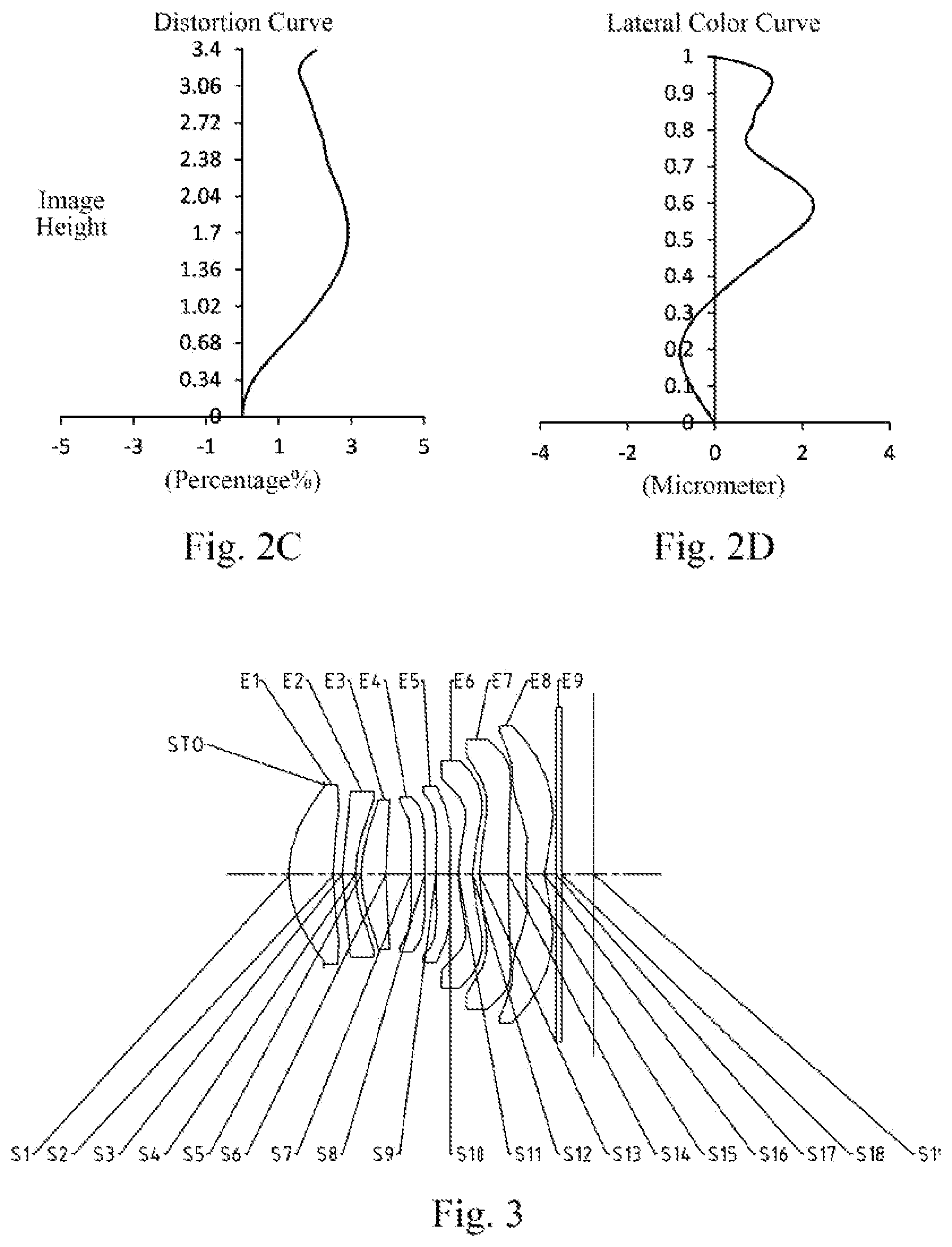
[0065] FIG. 2A illustrates a longitudinal aberration curve of the optical imaging lens group according to example 1, representing deviations of focal points converged by light of different wavelengths after passing through the lens group. FIG. 2B illustrates an astigmatic curve of the optical imaging lens group according to example 1, representing a curvature of a tangential plane and a curvature of a sagittal plane. FIG. 2C illustrates a distortion curve of the optical imaging lens group according to example 1, representing amounts of distortion corresponding to different image heights. FIG. 2D illustrates a lateral color curve of the optical imaging lens group according to example 1, representing deviations of different image heights on an imaging plane after light passes through the lens group. It can be seen from FIG. 2A to FIG. 2D that the optical imaging lens group provided in example 1 may achieve good image quality.
EXAMPLE 2
[0066] An optical imaging lens group according to example 2 of the present disclosure is described below with reference to FIG. 3 to FIG. 4D. In this example and the following examples, for the purpose of brevity, the description of parts similar to those in example 1 will be omitted. FIG. 3 shows a schematic structural view of the optical imaging lens group according to example 2 of the present disclosure.
[0067] As shown in FIG. 3, the optical imaging lens group according to an exemplary embodiment of the present disclosure includes a stop STO, a first lens E1, a second lens E2, a third lens E3, a fourth lens E4, a fifth lens E5, a sixth lens E6, a seventh lens E7, an eighth lens E8, an optical filter E9 and an imaging plane S19, which are sequentially arranged from an object side to an image side along an optical axis.
[0068] The first lens E1 has positive refractive power, an object-side surface S1 thereof is convex, and an image-side surface S2 thereof is concave. The second lens E2 has negative refractive power, an object-side surface S3 thereof is convex, and an image-side surface S4 thereof is concave. The third lens E3 has positive refractive power, an object-side surface S5 thereof is convex, and an image-side surface S6 thereof is concave. The fourth lens E4 has positive refractive power, an object-side surface S7 thereof is convex, and an image-side surface S8 thereof is concave. The fifth lens E5 has negative refractive power, an object-side surface S9 thereof is convex, and an image-side surface S10 thereof is concave. The sixth lens E6 has negative refractive power, an object-side surface S11 thereof is convex, and an image-side surface S12 thereof is concave. The seventh lens E7 has positive refractive power, an object-side surface S13 thereof is convex, and an image-side surface S14 thereof is convex. The eighth lens E8 has negative refractive power, an object-side surface S15 thereof is convex, and an image-side surface S16 thereof is concave. The optical filter E9 has an object-side surface S17 and an image-side surface S18. Light from an object sequentially passes through the respective surfaces S1 to S18 and is finally imaged on the imaging plane S19.
[0069] Table 4 shows surface type, radius of curvature, thickness, material and conic coefficient of each lens of the optical imaging lens group in example 2, wherein the units for the radius of curvature and the thickness are millimeter (mm). Table 5 shows high-order coefficients applicable to each aspheric surface in example 2, wherein the surface shape of each aspheric surface may be defined by the formula (1) given in the above example 1. Table 6 shows half of a diagonal length ImgH of an effective pixel area on the imaging plane S19 of the optical imaging lens group, a total optical length TTL, half of a maximal field-of-view HFOV, a total effective focal length f of the optical imaging lens group, and effective focal lengths f1 to f8 of respective lens in example 2.
TABLE-US-00004 TABLE 4 Material Surface Surface Radius of Refractive Abbe Conic number type curvature Thickness index number coefficient OBJ Spherical Infinite Infinite STO Spherical Infinite -0.6500 S1 Aspheric 2.1677 0.8200 1.55 64.1 -0.7422 S2 Aspheric 5.1798 0.1659 -40.2312 S3 Aspheric 3.0739 0.2400 1.67 20.4 -71.8317 S4 Aspheric 1.8963 0.1125 -6.3342 S5 Aspheric 2.2648 0.4500 1.55 64.1 -2.7537 S6 Aspheric 6.2470 0.4605 6.6951 S7 Aspheric 28.4000 0.2600 1.67 20.4 99.0000 S8 Aspheric 29.8836 0.2049 86.1010 S9 Aspheric 20.5563 0.2600 1.67 20.4 99.0000 S10 Aspheric 9.4269 0.1504 -82.8310 S11 Aspheric 2.4795 0.2600 1.66 21.5 -17.7809 S12 Aspheric 2.1862 0.1238 -17.6957 S13 Aspheric 2.7275 0.5346 1.55 64.1 -2.1788 S14 Aspheric -167.0194 0.3235 -99.0000 S15 Aspheric 2.4979 0.3382 1.55 64.1 -15.4914 S16 Aspheric 1.2082 0.2112 -6.0871 S17 Spherical Infinite 0.1100 1.52 64.1 S18 Spherical Infinite 0.5874 S19 Spherical Infinite
TABLE-US-00005 TABLE 5 Surface number A4 A6 A8 A10 A12 A14 A16 A18 A20 S1 6.8034E-03 1.0075E-03 5.7613E-03 -1.5765E-02 1.7623E-02 -1.0867E-02 3.8034E-03 -7.1392E-04 5.5321E-05 S2 2.5749E-02 -1.8294E-02 -1.7042E-02 2.8250E-02 -2.0808E-02 9.9251E-03 -3.0881E-03 5.5631E-04 -4.3482E-05 S3 1.4538E-01 -3.2664E-01 4.2695E-01 -4.2240E-01 3.0218E-01 -1.4510E-01 4.3926E-02 -7.5656E-03 5.6601E-04 S4 -4.2966E-02 2.1296E-01 -5.3235E-01 7.8203E-01 -7.6565E-01 5.0752E-01 -2.1825E-01 5.4738E-02 -6.0227E-03 S5 -6.0927E-02 2.0463E-01 -4.5252E-01 6.8982E-01 -7.4020E-01 5.3665E-01 -2.5187E-01 6.9081E-02 -8.2975E-03 S6 -2.3218E-02 1.6193E-02 -3.1755E-02 6.2035E-02 -1.0277E-01 1.0666E-01 -6.8798E-02 2.4868E-02 -3.7394E-03 S7 -3.0578E-02 4.5676E-03 -1.3918E-01 3.4485E-01 -4.8543E-01 4.1385E-01 -2.1303E-01 6.1287E-02 -7.5732E-03 S8 1.4736E-02 -1.6165E-01 3.5618E-01 -5.6702E-01 5.8523E-01 -3.9180E-01 1.6338E-01 -3.8332E-02 3.8518E-03 S9 1.8806E-02 -1.9567E-01 4.0224E-01 -4.8676E-01 3.7384E-01 -1.8952E-01 6.0843E-02 -1.1189E-02 9.0504E-04 S10 -2.6309E-03 -2.2775E-01 3.7467E-01 -3.4035E-01 1.8609E-01 -5.9059E-02 8.3280E-03 3.6331E-04 -1.7160E-04 S11 9.6429E-02 -2.1061E-01 1.7424E-01 -8.0474E-02 5.4376E-03 1.2631E-02 -6.3678E-03 1.3343E-03 -1.0782E-04 S12 9.4369E-02 -2.1635E-01 2.3417E-01 -1.6860E-01 7.9075E-02 -2.3694E-02 4.3515E-03 -4.4465E-04 1.9320E-05 S13 -3.4461E-02 -7.4697E-02 1.1925E-01 -9.6358E-02 4.4875E-02 -1.2498E-02 2.0516E-03 -1.8260E-04 6.7824E-06 S14 1.4447E-02 -2.0438E-02 3.7394E-02 -3.2467E-02 1.4757E-02 -3.7873E-03 5.5015E-04 -4.2154E-05 1.3244E-06 S15 -3.6662E-01 2.5850E-01 -1.1408E-01 3.8932E-02 -9.5669E-03 1.5215E-03 -1.4532E-04 7.5350E-06 -1.6265E-07 S16 -1.9688E-01 1.3586E-01 -6.7843E-02 2.4149E-02 -6.0801E-03 1.0442E-03 -1.1436E-04 7.0993E-06 -1.8831E-07
TABLE-US-00006 TABLE 6 ImgH (mm) 3.39 f3 (mm) 6.25 TTL (mm) 5.61 f4 (mm) 800.00 HFOV (.degree.) 36.5 f5 (mm) -26.31 f (mm) 4.36 f6 (mm) -43.37 f1 (mm) 6.22 f7 (mm) 4.91 f2 (mm) -8.07 f8 (mm) -4.72
[0070] FIG. 4A illustrates a longitudinal aberration curve of the optical imaging lens group according to example 2, representing deviations of focal points converged by light of different wavelengths after passing through the lens group. FIG. 4B illustrates an astigmatic curve of the optical imaging lens group according to example 2, representing a curvature of a tangential plane and a curvature of a sagittal plane. FIG. 4C illustrates a distortion curve of the optical imaging lens group according to example 2, representing amounts of distortion corresponding to different image heights. FIG. 4D illustrates a lateral color curve of the optical imaging lens group according to example 2, representing deviations of different image heights on an imaging plane after light passes through the lens group. It can be seen from FIG. 4A to FIG. 4D that the optical imaging lens group provided in example 2 may achieve good image quality.
EXAMPLE 3
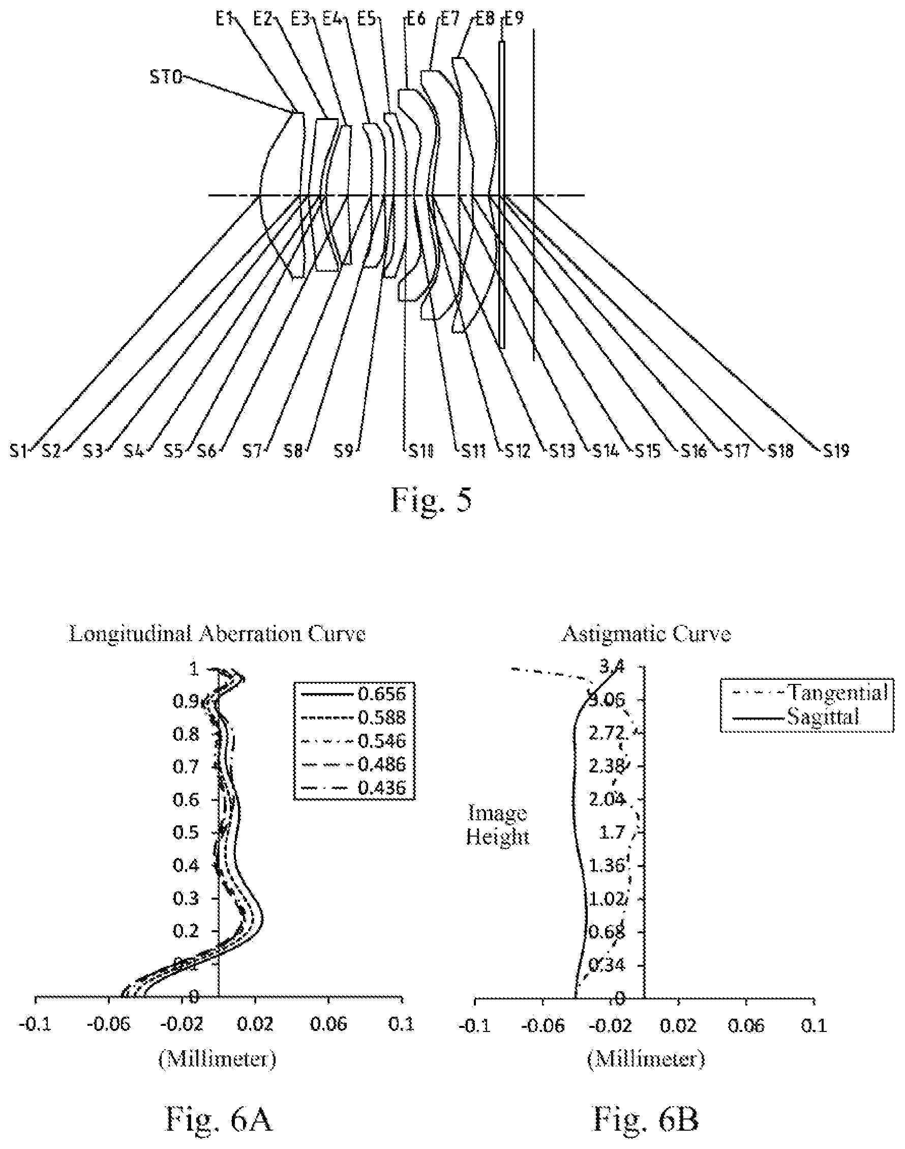
[0071] An optical imaging lens group according to example 3 of the present disclosure is described below with reference to FIG. 5 to FIG. 6D. FIG. 5 shows a schematic structural view of the optical imaging lens group according to example 3 of the present disclosure.
[0072] As shown in FIG. 5, the optical imaging lens group according to an exemplary embodiment of the present disclosure includes a stop STO, a first lens E1, a second lens E2,a third lens E3, a fourth lens E4, a fifth lens E5, a sixth lens E6, a seventh lens E7,an eighth lens E8, an optical filter E9 and an imaging plane S19, which are sequentially arranged from an object side to an image side along an optical axis.
[0073] The first lens E1 has positive refractive power, an object-side surface S1 thereof is convex, and an image-side surface S2 thereof is concave. The second lens E2 has negative refractive power, an object-side surface S3 thereof is convex, and an image-side surface S4 thereof is concave. The third lens E3 has positive refractive power, an object-side surface S5 thereof is convex, and an image-side surface S6 thereof is concave. The fourth lens E4 has negative refractive power, an object-side surface S7 thereof is convex, and an image-side surface S8 thereof is concave. The fifth lens E5 has positive refractive power, an object-side surface S9 thereof is convex, and an image-side surface S10 thereof is concave. The sixth lens E6 has negative refractive power, an object-side surface S11 thereof is convex, and an image-side surface S12 thereof is concave. The seventh lens E7 has positive refractive power, an object-side surface S13 thereof is convex, and an image-side surface S14 thereof is convex. The eighth lens E8 has negative refractive power, an object-side surface S15 thereof is convex, and an image-side surface S16 thereof is concave. The optical filter E9 has an object-side surface S17 and an image-side surface S18. Light from an object sequentially passes through the respective surfaces S1 to S18 and is finally imaged on the imaging plane S19.
[0074] Table 7 shows surface type, radius of curvature, thickness, material and conic coefficient of each lens of the optical imaging lens group in example 3, wherein the units for the radius of curvature and the thickness are millimeter (mm). Table 8 shows high-order coefficients applicable to each aspheric surface in example 3, wherein the surface shape of each aspheric surface may be defined by the formula (1) given in the above example 1. Table 9 shows half of a diagonal length ImgH of an effective pixel area on the imaging plane S19 of the optical imaging lens group, a total optical length TTL, half of a maximal field-of-view HFOV, a total effective focal length f of the optical imaging lens group, and effective focal lengths f1 to f8 of respective lens in example 3.
TABLE-US-00007 TABLE 7 Material Surface Surface Radius of Refractive Abbe Conic number type curvature Thickness index number coefficient OBJ Spherical Infinite Infinite STO Spherical Infinite -0.5960 S1 Aspheric 2.1837 0.8200 1.55 64.1 -0.7575 S2 Aspheric 5.4788 0.1735 -40.6538 S3 Aspheric 2.9972 0.2400 1.67 20.4 -53.4531 S4 Aspheric 1.8704 0.1211 -5.8677 S5 Aspheric 2.3745 0.4500 1.55 64.1 -2.5320 S6 Aspheric 6.3809 0.4752 7.5796 S7 Aspheric 12.2418 0.2777 1.67 20.4 42.4230 S8 Aspheric 10.6351 0.1850 24.8862 S9 Aspheric 15.5399 0.2600 1.67 20.4 97.6360 S10 Aspheric 15.8979 0.1526 50.7172 S11 Aspheric 2.8994 0.2654 1.66 21.5 -13.5612 S12 Aspheric 2.1216 0.1164 -13.8215 S13 Aspheric 2.4790 0.5400 1.55 64.1 -2.5145 S14 Aspheric -256.1456 0.2773 99.0000 S15 Aspheric 2.1925 0.3375 1.55 64.1 -14.6931 S16 Aspheric 1.1532 0.2152 -5.9096 S17 Spherical Infinite 0.1100 1.52 64.1 S18 Spherical Infinite 0.5925 S19 Spherical Infinite
TABLE-US-00008 TABLE 8 Surface number A4 A6 A8 A10 A12 A14 A16 A18 A20 S1 9.9323E-03 -1.0489E-02 3.0168E-02 -4.6768E-02 4.2102E-02 -2.2927E-02 7.3968E-03 -1.3056E-03 9.6580E-05 S2 1.9779E-02 -1.5703E-02 -2.6570E-04 -2.5731E-03 6.3763E-03 -4.4621E-03 1.5292E-03 -2.6912E-04 1.9391E-05 S3 1.0212E-01 -1.9303E-01 1.8604E-01 -1.2238E-01 4.7605E-02 -4.0438E-03 -4.3741E-03 1.6663E-03 -1.8565E-04 S4 -4.8177E-02 2.2067E-01 -5.1208E-01 7.1419E-01 -6.5959E-01 4.0393E-01 -1.5724E-01 3.5387E-02 -3.5127E-03 S5 -5.4668E-02 1.7904E-01 -3.8265E-01 5.4991E-01 -5.3887E-01 3.4625E-01 -1.4268E-01 3.5088E-02 -3.9261E-03 S6 -1.9789E-02 8.5745E-04 2.4625E-02 -7.9485E-02 1.1838E-01 -1.0322E-01 4.9454E-02 -1.1453E-02 9.2398E-04 S7 -4.0781E-02 4.0802E-02 -1.6620E-01 2.7586E-01 -2.9064E-01 1.9558E-01 -8.3233E-02 2.0939E-02 -2.4081E-03 S8 -1.5162E-02 -6.3385E-02 1.7029E-01 -3.2824E-01 3.8110E-01 -2.7757E-01 1.2237E-01 -2.9606E-02 3.0075E-03 S9 2.7670E-02 -2.8599E-01 6.3184E-01 -8.1417E-01 6.7000E-01 -3.5650E-01 1.1606E-01 -2.0543E-02 1.4698E-03 S10 1.0486E-01 -6.0793E-01 1.1035E+00 -1.2365E+00 9.1416E-01 -4.4362E-01 1.3458E-01 -2.2924E-02 1.6634E-03 S11 1.6202E-01 -4.2443E-01 5.4632E-01 -4.8347E-01 2.9309E-01 -1.2032E-01 3.1183E-02 -4.4875E-03 2.6948E-04 S12 7.3082E-02 -1.4899E-01 1.2054E-01 -5.6745E-02 1.4852E-02 -1.9187E-03 5.1662E-05 1.2863E-05 -9.6926E-07 S13 -8.6218E-02 4.7561E-02 -2.4310E-02 9.7020E-04 3.8588E-03 -1.5617E-03 2.6641E-04 -2.0796E-05 5.7588E-07 S14 -2.3301E-02 5.2621E-02 -1.7117E-02 -1.2179E-02 1.0791E-02 -3.4463E-03 5.5658E-04 -4.5388E-05 1.4870E-06 S15 -3.8078E-01 2.8814E-01 -1.3252E-01 4.4323E-02 -1.0390E-02 1.5852E-03 -1.4730E-04 7.5350E-06 -1.6265E-07 S16 -2.0096E-01 1.4221E-01 -7.0864E-02 2.4189E-02 -5.7367E-03 9.3641E-04 -9.9357E-05 6.0710E-06 -1.5996E-07
TABLE-US-00009 TABLE 9 ImgH (mm) 3.39 f3 (mm) 6.65 TTL (mm) 5.61 f4 (mm) -130.29 HFOV (.degree.) 36.7 f5 (mm) 800.00 f (mm) 4.36 f6 (mm) -13.91 f1 (mm) 6.11 f7 (mm) 4.50 f2 (mm) -8.14 f8 (mm) -5.03
[0075] FIG. 6A illustrates a longitudinal aberration curve of the optical imaging lens group according to example 3, representing deviations of focal points converged by light of different wavelengths after passing through the lens group. FIG. 6B illustrates an astigmatic curve of the optical imaging lens group according to example 3, representing a curvature of a tangential plane and a curvature of a sagittal plane. FIG. 6C illustrates a distortion curve of the optical imaging lens group according to example 3, representing amounts of distortion corresponding to different image heights. FIG. 6D illustrates a lateral color curve of the optical imaging lens group according to example 3, representing deviations of different image heights on an imaging plane after light passes through the lens group. It can be seen from FIG. 6A to FIG. 6D that the optical imaging lens group provided in example 3 may achieve good image quality.
EXAMPLE 4
[0076] An optical imaging lens group according to example 4 of the present disclosure is described below with reference to FIG. 7 to FIG. 8D. FIG. 7 shows a schematic structural view of the optical imaging lens group according to example 4 of the present disclosure.
[0077] As shown in FIG. 7, the optical imaging lens group according to an exemplary embodiment of the present disclosure includes a stop STO, a first lens E1, a second lens E2, a third lens E3, a fourth lens E4, a fifth lens E5, a sixth lens E6, a seventh lens E7, an eighth lens E8, an optical filter E9 and an imaging plane S19, which are sequentially arranged from an object side to an image side along an optical axis.
[0078] The first lens E1 has positive refractive power, an object-side surface S1 thereof is convex, and an image-side surface S2 thereof is concave. The second lens E2 has negative refractive power, an object-side surface S3 thereof is convex, and an image-side surface S4 thereof is concave. The third lens E3 has positive refractive power, an object-side surface S5 thereof is convex, and an image-side surface S6 thereof is concave. The fourth lens E4 has negative refractive power, an object-side surface S7 thereof is convex, and an image-side surface S8 thereof is concave. The fifth lens E5 has negative refractive power, an object-side surface S9 thereof is convex, and an image-side surface S10 thereof is concave. The sixth lens E6 has positive refractive power, an object-side surface S11 thereof is convex, and an image-side surface S12 thereof is concave. The seventh lens E7 has positive refractive power, an object-side surface S13 thereof is convex, and an image-side surface S14 thereof is convex. The eighth lens E8 has negative refractive power, an object-side surface S15 thereof is convex, and an image-side surface S16 thereof is concave. The optical filter E9 has an object-side surface S17 and an image-side surface S18. Light from an object sequentially passes through the respective surfaces S1 to S18 and is finally imaged on the imaging plane S19.
[0079] Table 10 shows surface type, radius of curvature, thickness, material and conic coefficient of each lens of the optical imaging lens group in example 4, wherein the units for the radius of curvature and the thickness are millimeter (mm). Table 11 shows high-order coefficients applicable to each aspheric surface in example 4, wherein the surface shape of each aspheric surface may be defined by the formula (1) given in the above example 1. Table 12 shows half of a diagonal length ImgH of an effective pixel area on the imaging plane S19 of the optical imaging lens group, a total optical length TTL, half of a maximal field-of-view HFOV, a total effective focal length f of the optical imaging lens group, and effective focal lengths f1 to f8 of respective lens in example 4.
TABLE-US-00010 TABLE 10 Material Surface Surface Radius of Refractive Abbe Conic number type curvature Thickness index number coefficient OBJ Spherical Infinite Infinite STO Spherical Infinite -0.5960 S1 Aspheric 2.1478 0.7729 1.55 64.1 -0.8468 S2 Aspheric 4.9610 0.1760 -42.1391 S3 Aspheric 3.0352 0.2400 1.67 20.4 -58.9212 S4 Aspheric 1.9063 0.1127 -6.3221 S5 Aspheric 2.3079 0.4500 1.55 64.1 -2.8642 S6 Aspheric 6.5335 0.4810 3.2060 S7 Aspheric 33.9302 0.2792 1.67 20.4 99.0000 S8 Aspheric 20.0571 0.1416 50.1638 S9 Aspheric 15.3461 0.2657 1.67 20.4 98.4656 S10 Aspheric 7.5724 0.1292 -58.0704 S11 Aspheric 2.3243 0.2600 1.66 21.5 -15.8037 S12 Aspheric 2.2624 0.1409 -16.3715 S13 Aspheric 3.2310 0.5400 1.55 64.1 -1.0975 S14 Aspheric -10.8610 0.2942 -99.0000 S15 Aspheric 2.6756 0.3725 1.55 64.1 -13.0546 S16 Aspheric 1.2031 0.2177 -5.4747 S17 Spherical Infinite 0.1100 1.52 64.1 S18 Spherical Infinite 0.5993 S19 Spherical Infinite
TABLE-US-00011 TABLE 11 Surface number A4 A6 A8 A10 A12 A14 A16 A18 A20 S1 1.1309E-02 -9.3711E-03 2.7693E-02 -4.4818E-02 4.2442E-02 -2.4461E-02 8.3742E-03 -1.5715E-03 1.2364E-04 S2 2.9224E-02 -3.6090E-02 3.2491E-02 -4.4222E-02 4.2173E-02 -2.3910E-02 7.9096E-03 -1.4225E-03 1.0746E-04 S3 1.1213E-01 -2.4576E-01 2.9821E-01 -2.6834E-01 1.6899E-01 -6.6836E-02 1.4868E-02 -1.4805E-03 2.1180E-05 S4 -5.2626E-02 2.3699E-01 -5.8988E-01 9.0753E-01 -9.3950E-01 6.5079E-01 -2.8636E-01 7.1947E-02 -7.8096E-03 S5 -5.6988E-02 1.9988E-01 -4.6127E-01 7.3126E-01 -8.0400E-01 5.8425E-01 -2.6928E-01 7.1534E-02 -8.2789E-03 S6 -1.8541E-02 6.7138E-03 -3.7444E-04 -1.4795E-02 1.6099E-02 -9.8358E-03 -7.7799E-06 2.7023E-03 -7.6103E-04 S7 -3.5806E-02 -4.4276E-03 -3.3534E-02 2.0078E-02 2.9894E-02 -5.7360E-02 3.6849E-02 -1.0192E-02 9.6813E-04 S8 -7.4658E-03 -1.0043E-01 2.5946E-01 -4.6492E-01 5.1903E-01 -3.6783E-01 1.5915E-01 -3.8068E-02 3.8453E-03 S9 -7.2836E-03 -1.9174E-01 5.0970E-01 -7.0092E-01 5.8411E-01 -3.0536E-01 9.5487E-02 -1.5835E-02 1.0074E-03 S10 -3.1758E-03 -3.4789E-01 7.5181E-01 -9.0236E-01 6.8375E-01 -3.3189E-01 9.9222E-02 -1.6516E-02 1.1678E-03 S11 1.4089E-01 -3.9535E-01 5.3446E-01 -4.7912E-01 2.7971E-01 -1.0723E-01 2.5639E-02 -3.3676E-03 1.8047E-04 S12 1.1763E-01 -2.8608E-01 3.3937E-01 -2.5335E-01 1.1876E-01 -3.4966E-02 6.2793E-03 -6.2798E-04 2.6777E-05 S13 -7.8651E-03 -1.0651E-01 1.4898E-01 -1.0875E-01 4.5730E-02 -1.1489E-02 1.6950E-03 -1.3448E-04 4.3930E-06 S14 1.3196E-02 -2.4600E-02 5.6542E-02 -4.8009E-02 2.0785E-02 -5.0984E-03 7.1404E-04 -5.3179E-05 1.6345E-06 S15 -3.7500E-01 2.6674E-01 -1.1906E-01 4.0593E-02 -9.8522E-03 1.5454E-03 -1.4610E-04 7.5350E-06 -1.6265E-07 S16 -1.9746E-01 1.4507E-01 -7.7014E-02 2.8857E-02 -7.5130E-03 1.3066E-03 -1.4249E-04 8.7125E-06 -2.2627E-07
TABLE-US-00012 TABLE 12 ImgH (mm) 3.39 f3 (mm) 6.29 TTL (mm) 5.58 f4 (mm) -74.01 HFOV (.degree.) 37.2 f5 (mm) -22.68 f (mm) 4.32 f6 (mm) 194.01 f1 (mm) 6.32 f7 (mm) 4.62 f2 (mm) -8.39 f8 (mm) -4.39
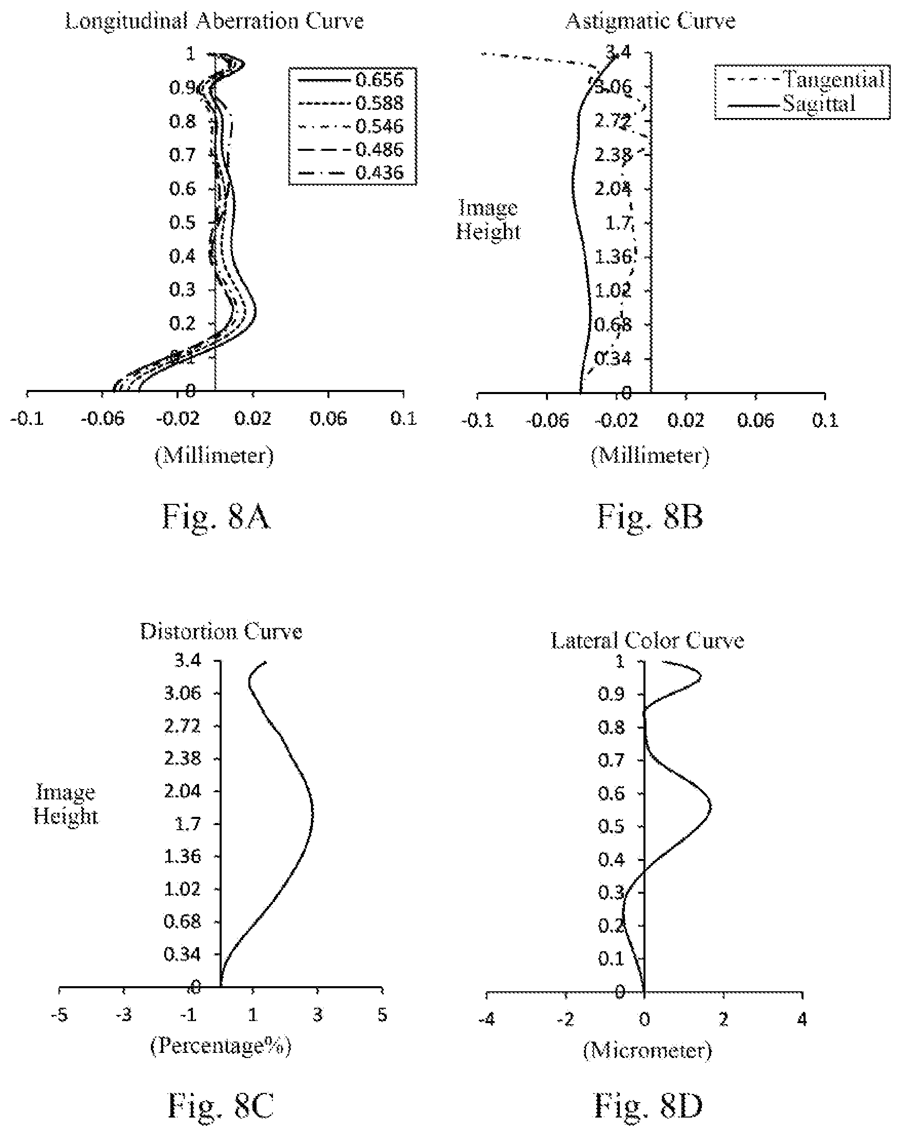
[0080] FIG. 8A illustrates a longitudinal aberration curve of the optical imaging lens group according to example 4, representing deviations of focal points converged by light of different wavelengths after passing through the lens group. FIG. 8B illustrates an astigmatic curve of the optical imaging lens group according to example 4, representing a curvature of a tangential plane and a curvature of a sagittal plane. FIG. 8C illustrates a distortion curve of the optical imaging lens group according to example 4, representing amounts of distortion corresponding to different image heights. FIG. 8D illustrates a lateral color curve of the optical imaging lens group according to example 4, representing deviations of different image heights on an imaging plane after light passes through the lens group. It can be seen from FIG. 8A to FIG. 8D that the optical imaging lens group provided in example 4 may achieve good image quality.
EXAMPLE 5
[0081] An optical imaging lens group according to example 5 of the present disclosure is described below with reference to FIG. 9 to FIG. 10D. FIG. 9 shows a schematic structural view of the optical imaging lens group according to example 5 of the present disclosure.
[0082] As shown in FIG. 9, the optical imaging lens group according to an exemplary embodiment of the present disclosure includes a stop STO, a first lens E1, a second lens E2, a third lens E3, a fourth lens E4, a fifth lens E5, a sixth lens E6, a seventh lens E7, an eighth lens E8, an optical filter E9 and an imaging plane S19, which are sequentially arranged from an object side to an image side along an optical axis.
[0083] The first lens E1 has positive refractive power, an object-side surface S1 thereof is convex, and an image-side surface S2 thereof is concave. The second lens E2 has negative refractive power, an object-side surface S3 thereof is convex, and an image-side surface S4 thereof is concave. The third lens E3 has positive refractive power, an object-side surface S5 thereof is convex, and an image-side surface S6 thereof is concave. The fourth lens E4 has negative refractive power, an object-side surface S7 thereof is convex, and an image-side surface S8 thereof is concave. The fifth lens E5 has negative refractive power, an object-side surface S9 thereof is convex, and an image-side surface S10 thereof is concave. The sixth lens E6 has negative refractive power, an object-side surface S11 thereof is convex, and an image-side surface S12 thereof is concave. The seventh lens E7 has positive refractive power, an object-side surface S13 thereof is convex, and an image-side surface S14 thereof is concave. The eighth lens E8 has positive refractive power, an object-side surface S15 thereof is convex, and an image-side surface S16 thereof is concave. The optical filter E9 has an object-side surface S17 and an image-side surface S18. Light from an object sequentially passes through the respective surfaces S1 to S18 and is finally imaged on the imaging plane S19.
[0084] Table 13 shows surface type, radius of curvature, thickness, material and conic coefficient of each lens of the optical imaging lens group in example 5, wherein the units for the radius of curvature and the thickness are millimeter (mm). Table 14 shows high-order coefficients applicable to each aspheric surface in example 5, wherein the surface shape of each aspheric surface may be defined by the formula (1) given in the above example 1. Table 15 shows half of a diagonal length ImgH of an effective pixel area on the imaging plane S19 of the optical imaging lens group, a total optical length TTL, half of a maximal field-of-view HFOV, a total effective focal length f of the optical imaging lens group, and effective focal lengths f1 to f8 of respective lens in example 5.
TABLE-US-00013 TABLE 13 Material Surface Surface Radius of Refractive Abbe Conic number type curvature Thickness index number coefficient OBJ Spherical Infinite Infinite STO Spherical Infinite -0.5960 S1 Aspheric 2.1806 0.8130 1.55 64.1 -0.6555 S2 Aspheric 6.0388 0.1424 -36.7159 S3 Aspheric 2.9391 0.2400 1.67 20.4 -33.5593 S4 Aspheric 1.8325 0.1310 -4.9646 S5 Aspheric 2.4586 0.4358 1.55 64.1 -1.8707 S6 Aspheric 6.3641 0.4974 16.1115 S7 Aspheric 14.6534 0.2600 1.67 20.4 99.0000 S8 Aspheric 13.7677 0.1933 71.8112 S9 Aspheric 14.6937 0.2700 1.67 20.4 83.2284 S10 Aspheric 8.2843 0.1388 11.3999 S11 Aspheric 2.7573 0.3000 1.66 21.5 -11.3409 S12 Aspheric 2.3604 0.1210 -18.5432 S13 Aspheric 2.7105 0.5000 1.55 64.1 -1.7712 S14 Aspheric 3.2880 0.1778 -96.5539 S15 Aspheric 1.2994 0.4543 1.55 64.1 -6.6126 S16 Aspheric 1.1415 0.2485 -3.9192 S17 Spherical Infinite 0.1100 1.52 64.1 S18 Spherical Infinite 0.5981 S19 Spherical Infinite
TABLE-US-00014 TABLE 14 Surface number A4 A6 A8 A10 A12 A14 A16 A18 A20 S1 1.1341E-02 -1.8769E-02 4.2712E-02 -5.6384E-02 4.4795E-02 -2.2080E-02 6.5645E-03 -1.0870E-03 7.6841E-05 S2 9.4355E-03 1.7224E-02 -7.2100E-02 8.9693E-02 -6.6751E-02 3.1891E-02 -9.5570E-03 1.6330E-03 -1.2153E-04 S3 7.2169E-02 -1.2596E-01 1.2278E-01 -1.1330E-01 8.7271E-02 -4.5869E-02 1.5267E-02 -2.9245E-03 2.4627E-04 S4 -3.1018E-02 1.3735E-01 -2.9383E-01 3.7185E-01 -3.1434E-01 1.7837E-01 -6.5817E-02 1.4736E-02 -1.5423E-03 S5 -3.0627E-02 3.8879E-02 2.6959E-02 -1.8127E-01 2.9429E-01 -2.5909E-01 1.2725E-01 -3.1959E-02 3.1739E-03 S6 -1.9582E-02 -9.3712E-03 4.8353E-02 -1.2638E-01 1.8489E-01 -1.6576E-01 8.5306E-02 -2.2727E-02 2.4217E-03 S7 -2.5889E-02 4.6141E-03 -1.0896E-01 2.3723E-01 -3.0942E-01 2.5220E-01 -1.2754E-01 3.6695E-02 -4.5686E-03 S8 2.9682E-04 -9.3471E-02 2.0035E-01 -3.3853E-01 3.6657E-01 -2.5448E-01 1.0775E-01 -2.5120E-02 2.4694E-03 S9 1.3577E-02 -2.3724E-01 5.2717E-01 -6.5024E-01 4.8670E-01 -2.2056E-01 5.4388E-02 -5.2294E-03 -1.2202E-04 S10 6.4355E-02 -5.5528E-01 1.0697E+00 -1.2163E+00 8.8945E-01 -4.1987E-01 1.2279E-01 -2.0098E-02 1.4013E-03 S11 1.5500E-01 -4.5318E-01 6.1667E-01 -5.4848E-01 3.2011E-01 -1.2241E-01 2.8956E-02 -3.7393E-03 1.9641E-04 S12 8.2113E-02 -1.5411E-01 1.3775E-01 -8.0091E-02 2.8903E-02 -6.4583E-03 8.8412E-04 -7.0096E-05 2.5753E-06 S13 -1.6545E-01 2.1710E-01 -1.9741E-01 9.9873E-02 -3.0664E-02 6.1125E-03 -8.1267E-04 6.7772E-05 -2.6727E-06 S14 -1.8675E-01 3.3651E-01 -2.7614E-01 1.2789E-01 -3.6375E-02 6.5408E-03 -7.3294E-04 4.7092E-05 -1.3294E-06 S15 -4.1869E-01 3.7100E-01 -2.0633E-01 7.8233E-02 -1.9638E-02 3.1585E-03 -3.1206E-04 1.7270E-05 -4.1101E-07 S16 -2.2881E-01 1.7325E-01 -9.2388E-02 3.3034E-02 -7.9216E-03 1.2567E-03 -1.2582E-04 7.1580E-06 -1.7548E-07
TABLE-US-00015 TABLE 15 ImgH (mm) 3.39 f3 (mm) 7.05 TTL (mm) 5.63 f4 (mm) -386.34 HFOV (.degree.) 36.2 f5 (mm) -28.91 f (mm) 4.50 f6 (mm) -35.62 f1 (mm) 5.81 f7 (mm) 21.62 f2 (mm) -7.98 f8 (mm) 999.64
[0085] FIG. 10A illustrates a longitudinal aberration curve of the optical imaging lens group according to example 5, representing deviations of focal points converged by light of different wavelengths after passing through the lens group. FIG. 10B illustrates an astigmatic curve of the optical imaging lens group according to example 5, representing a curvature of a tangential plane and a curvature of a sagittal plane. FIG. 10C illustrates a distortion curve of the optical imaging lens group according to example 5, representing amounts of distortion corresponding to different image heights. FIG. 10D illustrates a lateral color curve of the optical imaging lens group according to example 5, representing deviations of different image heights on an imaging plane after light passes through the lens group. It can be seen from FIG. 10A to FIG. 10D that the optical imaging lens group provided in example 5 may achieve good image quality.
EXAMPLE 6
[0086] An optical imaging lens group according to example 6 of the present disclosure is described below with reference to FIG. 11 to FIG. 12D. FIG. 11 shows a schematic structural view of the optical imaging lens group according to example 6 of the present disclosure.
[0087] As shown in FIG. 11, the optical imaging lens group according to an exemplary embodiment of the present disclosure includes a stop STO, a first lens E1, a second lens E2, a third lens E3, a fourth lens E4, a fifth lens E5, a sixth lens E6, a seventh lens E7, an eighth lens E8, an optical filter E9 and an imaging plane S19, which are sequentially arranged from an object side to an image side along an optical axis.
[0088] The first lens E1 has positive refractive power, an object-side surface S1 thereof is convex, and an image-side surface S2 thereof is concave. The second lens E2 has negative refractive power, an object-side surface S3 thereof is convex, and an image-side surface S4 thereof is concave. The third lens E3 has positive refractive power, an object-side surface S5 thereof is convex, and an image-side surface S6 thereof is convex. The fourth lens E4 has negative refractive power, an object-side surface S7 thereof is convex, and an image-side surface S8 thereof is concave. The fifth lens E5 has negative refractive power, an object-side surface S9 thereof is convex, and an image-side surface S10 thereof is concave. The sixth lens E6 has negative refractive power, an object-side surface S11 thereof is convex, and an image-side surface S12 thereof is concave. The seventh lens E7 has positive refractive power, an object-side surface S13 thereof is convex, and an image-side surface S14 thereof is convex. The eighth lens E8 has negative refractive power, an object-side surface S15 thereof is convex, and an image-side surface S16 thereof is concave. The optical filter E9 has an object-side surface S17 and an image-side surface S18. Light from an object sequentially passes through the respective surfaces S1 to S18 and is finally imaged on the imaging plane S19.
[0089] Table 16 shows surface type, radius of curvature, thickness, material and conic coefficient of each lens of the optical imaging lens group in example 6, wherein the units for the radius of curvature and the thickness are millimeter (mm). Table 17 shows high-order coefficients applicable to each aspheric surface in example 6, wherein the surface shape of each aspheric surface may be defined by the formula (1) given in the above example 1. Table 18 shows half of a diagonal length ImgH of an effective pixel area on the imaging plane S19 of the optical imaging lens group, a total optical length TTL, half of a maximal field-of-view HFOV, a total effective focal length f of the optical imaging lens group, and effective focal lengths f1 to f8 of respective lens in example 6.
TABLE-US-00016 TABLE 16 Material Surface Surface Radius of Refractive Abbe Conic number type curvature Thickness index number coefficient OBJ Spherical Infinite Infinite STO Spherical Infinite -0.5960 S1 Aspheric 2.1902 0.8192 1.55 64.1 -0.6647 S2 Aspheric 7.5179 0.1213 -54.2436 S3 Aspheric 2.7217 0.2400 1.67 20.4 -43.0662 S4 Aspheric 1.9034 0.2643 -5.8689 S5 Aspheric 4.4577 0.4469 1.55 64.1 -1.6534 S6 Aspheric -800.0000 0.2636 99.0000 S7 Aspheric 175.5418 0.2600 1.67 20.4 -97.7633 S8 Aspheric 14.7219 0.2802 85.0742 S9 Aspheric 14.3021 0.2852 1.67 20.4 77.8741 S10 Aspheric 9.8009 0.1501 10.6350 S11 Aspheric 2.5808 0.3000 1.66 21.5 -9.6253 S12 Aspheric 2.1255 0.1234 -15.3587 S13 Aspheric 2.5472 0.5000 1.55 64.1 -1.9675 S14 Aspheric -46.7686 0.2728 -95.9546 S15 Aspheric 2.2259 0.3375 1.55 64.1 -12.0286 S16 Aspheric 1.1363 0.2189 -5.6035 S17 Spherical Infinite 0.1100 1.52 64.1 S18 Spherical Infinite 0.5980 S19 Spherical Infinite
TABLE-US-00017 TABLE 17 Surface number A4 A6 A8 A10 A12 S1 6.2497E-03 5.8948E-03 -1.1493E-02 1.4238E-02 -1.1378E-02 S2 -1.4352E-02 2.5038E-02 -9.7594E-03 -2.5376E-02 3.6861E-02 S3 9.8701E-02 -2.7446E-01 4.4187E-01 -4.9277E-01 3.6640E-01 S4 -2.0283E-02 4.8495E-02 -8.5929E-02 1.1861E-01 -1.4726E-01 S5 -1.1547E-02 -4.5140E-03 8.7181E-02 -2.6058E-01 3.8107E-01 S6 -7.8778E-03 -5.8973E-02 2.1384E-01 -4.5162E-01 5.7896E-01 S7 -2.4313E-02 -4.3686E-02 1.0133E-01 -2.2946E-01 3.1390E-01 S8 -1.0183E-02 -8.0375E-02 2.0607E-01 -3.6769E-01 3.9390E-01 S9 2.2094E-05 -1.6607E-01 3.2612E-01 -2.9876E-01 1.0712E-01 S10 6.6629E-02 -5.4086E-01 1.0089E+00 -1.1174E+00 7.9972E-01 S11 1.4269E-01 -3.8560E-01 5.0801E-01 -4.5461E-01 2.6989E-01 S12 8.0786E-02 -1.4692E-01 1.2917E-01 -7.8949E-02 3.1847E-02 S13 -1.0291E-01 5.8547E-02 -2.8067E-02 1.0445E-03 4.5142E-03 S14 -6.1800E-03 2.2405E-02 5.1669E-03 -2.2762E-02 1.4703E-02 S15 -3.8784E-01 3.0451E-01 -1.6059E-01 6.3836E-02 -1.7314E-02 S16 -1.9921E-01 1.4290E-01 -7.4573E-02 2.7005E-02 -6.7466E-03 Surface number A14 A16 A18 A20 S1 5.5957E-03 -1.6596E-03 2.5511E-04 -1.5154E-05 S2 -2.3641E-02 8.3275E-03 -1.5584E-03 1.2084E-04 S3 -1.7695E-01 5.3705E-02 -9.3270E-03 7.0583E-04 S4 1.3173E-01 -7.3119E-02 2.2540E-02 -2.9161E-03 S5 -3.2609E-01 1.6013E-01 -4.1073E-02 4.2648E-03 S6 -4.6536E-01 2.2575E-01 -5.9913E-02 6.6813E-03 S7 -2.6901E-01 1.3988E-01 -4.0160E-02 4.8714E-03 S8 -2.6575E-01 1.1031E-01 -2.5695E-02 2.5688E-03 S9 3.0019E-02 -4.3830E-02 1.5767E-02 -2.0052E-03 S10 -3.7227E-01 1.0812E-01 -1.7639E-02 1.2256E-03 S11 -1.0571E-01 2.5703E-02 -3.4131E-03 1.8403E-04 S12 -8.3703E-03 1.3843E-03 -1.3048E-04 5.3174E-06 S13 -1.8940E-03 3.4173E-04 -2.8856E-05 8.9965E-07 S14 -4.4887E-03 7.2986E-04 -6.0987E-05 2.0631E-06 S15 2.9710E-03 -3.0605E-04 1.7270E-05 -4.1101E-07 S16 1.1428E-03 -1.2423E-04 7.7248E-06 -2.0681E-07
TABLE-US-00018 TABLE 18 ImgH (mm) 3.39 f3 (mm) 8.11 TTL (mm) 5.59 f4 (mm) -24.07 HFOV (.degree.) 37.0 f5 (mm) -47.82 f (mm) 4.32 f6 (mm) -24.81 f1 (mm) 5.36 f7 (mm) 4.44 f2 (mm) -10.74 f8 (mm) -4.77
[0090] FIG. 12A illustrates a longitudinal aberration curve of the optical imaging lens group according to example 6, representing deviations of focal points converged by light of different wavelengths after passing through the lens group. FIG. 12B illustrates an astigmatic curve of the optical imaging lens group according to example 6, representing a curvature of a tangential plane and a curvature of a sagittal plane. FIG. 12C illustrates a distortion curve of the optical imaging lens group according to example 6, representing amounts of distortion corresponding to different image heights. FIG. 12D illustrates a lateral color curve of the optical imaging lens group according to example 6, representing deviations of different image heights on an imaging plane after light passes through the lens group. It can be seen from FIG. 12A to FIG. 12D that the optical imaging lens group provided in example 6 may achieve good image quality.
EXAMPLE 7
[0091] An optical imaging lens group according to example 7 of the present disclosure is described below with reference to FIG. 13 to FIG. 14D. FIG. 13 shows a schematic structural view of the optical imaging lens group according to example 7 of the present disclosure.
[0092] As shown in FIG. 13, the optical imaging lens group according to an exemplary embodiment of the present disclosure includes a stop STO, a first lens E1, a second lens E2, a third lens E3, a fourth lens E4,a fifth lens E5, a sixth lens E6, a seventh lens E7, an eighth lens E8, an optical filter E9 and an imaging plane S19, which are sequentially arranged from an object side to an image side along an optical axis.
[0093] The first lens E1 has positive refractive power, an object-side surface S1 thereof is convex, and an image-side surface S2 thereof is concave. The second lens E2 has negative refractive power, an object-side surface S3 thereof is convex, and an image-side surface S4 thereof is concave. The third lens E3 has positive refractive power, an object-side surface S5 thereof is convex, and an image-side surface S6 thereof is concave. The fourth lens E4 has positive refractive power, an object-side surface S7 thereof is concave, and an image-side surface S8 thereof is convex. The fifth lens E5 has negative refractive power, an object-side surface S9 thereof is convex, and an image-side surface S10 thereof is concave. The sixth lens E6 has positive refractive power, an object-side surface S11 thereof is convex, and an image-side surface S12 thereof is concave. The seventh lens E7 has positive refractive power, an object-side surface S13 thereof is convex, and an image-side surface S14 thereof is convex. The eighth lens E8 has negative refractive power, an object-side surface S15 thereof is convex, and an image-side surface S16 thereof is concave. The optical filter E9 has an object-side surface S17 and an image-side surface S18. Light from an object sequentially passes through the respective surfaces S1 to S18 and is finally imaged on the imaging plane S19.
[0094] Table 19 shows surface type, radius of curvature, thickness, material and conic coefficient of each lens of the optical imaging lens group in example 7, wherein the units for the radius of curvature and the thickness are millimeter (mm). Table 20 shows high-order coefficients applicable to each aspheric surface in example 7, wherein the surface shape of each aspheric surface may be defined by the formula (1) given in the above example 1. Table 21 shows half of a diagonal length ImgH of an effective pixel area on the imaging plane S19 of the optical imaging lens group, a total optical length TTL, half of a maximal field-of-view HFOV, a total effective focal length f of the optical imaging lens group, and effective focal lengths f1 to f8 of respective lens in example 7.
TABLE-US-00019 TABLE 19 Material Surface Surface Radius of Refractive Abbe Conic number type curvature Thickness index number coefficient OBJ Spherical Infinite Infinite STO Spherical Infinite -0.6300 S1 Aspheric 2.1602 0.8200 1.55 64.1 -0.6742 S2 Aspheric 5.1264 0.1461 -36.1902 S3 Aspheric 2.8761 0.2400 1.67 20.4 -48.2921 S4 Aspheric 1.8142 0.1228 -5.7485 S5 Aspheric 2.2268 0.4500 1.55 64.1 -2.6670 S6 Aspheric 6.1117 0.5757 8.8359 S7 Aspheric -1000.0000 0.2600 1.67 20.4 -99.0000 S8 Aspheric -508.7416 0.0946 -99.0000 S9 Aspheric 45.6612 0.2600 1.67 20.4 99.0000 S10 Aspheric 9.5031 0.1502 -14.8796 S11 Aspheric 1.9831 0.2600 1.66 21.5 -16.7653 S12 Aspheric 1.9072 0.1346 -16.0744 S13 Aspheric 4.0317 0.5400 1.55 64.1 0.0409 S14 Aspheric -5.1098 0.2685 -38.5057 S15 Aspheric 2.7399 0.3375 1.55 64.1 -14.7076 S16 Aspheric 1.1493 0.2211 -5.6358 S17 Spherical Infinite 0.1100 1.52 64.1 S18 Spherical Infinite 0.5890 S19 Spherical Infinite
TABLE-US-00020 TABLE 20 Surface number A4 A6 A8 A10 A12 S1 7.9111E-03 -2.6890E-03 1.1137E-02 -1.9523E-02 1.8149E-02 S2 2.4284E-02 -1.4666E-02 -1.2882E-02 9.2180E-03 3.1198E-03 S3 1.1056E-01 -2.0540E-01 2.1418E-01 -1.8621E-01 1.2967E-01 S4 -4.6675E-02 1.9886E-01 -4.2480E-01 5.3249E-01 -4.3975E-01 S5 -5.4241E-02 1.6034E-01 -3.0951E-01 4.1765E-01 -4.0496E-01 S6 -1.8077E-02 8.1369E-03 -1.4192E-02 2.4597E-02 -4.0954E-02 S7 -1.7789E-02 -7.0820E-02 1.3879E-01 -2.4112E-01 2.6425E-01 S8 7.7441E-02 -4.2194E-01 1.0244E+00 -1.6132E+00 1.6054E+00 S9 1.0742E-01 -5.3276E-01 1.2168E+00 -1.6684E+00 1.4283E+00 S10 -1.0211E-02 -2.6521E-01 5.4493E-01 -6.0574E-01 4.0222E-01 S11 1.2965E-01 -2.9366E-01 3.3656E-01 -2.5776E-01 1.2151E-01 S12 1.3003E-01 -2.6369E-01 2.8334E-01 -2.0051E-01 8.9878E-02 S13 5.7254E-03 -1.0500E-01 1.3051E-01 -8.7564E-02 3.3899E-02 S14 2.1073E-02 -5.8337E-02 9.1082E-02 -6.3829E-02 2.4609E-02 S15 -3.9933E-01 2.8681E-01 -1.2756E-01 4.2716E-02 -1.0156E-02 S16 -2.1395E-01 1.6150E-01 -8.6607E-02 3.2569E-02 -8.4836E-03 Surface number A14 A16 A18 A20 S1 -9.9181E-03 3.1627E-03 -5.5003E-04 3.9753E-05 S2 -5.5673E-03 2.5102E-03 -5.1553E-04 4.1255E-05 S3 -6.3225E-02 1.9817E-02 -3.5889E-03 2.8639E-04 S4 2.4675E-01 -9.2023E-02 2.0855E-02 -2.1611E-03 S5 2.7010E-01 -1.2073E-01 3.2813E-02 -3.9991E-03 S6 3.9631E-02 -2.5521E-02 9.7942E-03 -1.5727E-03 S7 -1.7420E-01 6.3265E-02 -1.0321E-02 3.2665E-04 S8 -1.0110E+00 3.8962E-01 -8.3707E-02 7.6772E-03 S9 -7.7297E-01 2.5653E-01 -4.7791E-02 3.8457E-03 S10 -1.5899E-01 3.4675E-02 -3.3558E-03 5.0160E-05 S11 -3.4585E-02 5.3904E-03 -3.1711E-04 -7.2487E-06 S12 -2.5188E-02 4.2798E-03 -4.0349E-04 1.6206E-05 S13 -7.7654E-03 1.0289E-03 -7.1735E-05 1.9854E-06 S14 -5.5830E-03 7.3973E-04 -5.2882E-05 1.5755E-06 S15 1.5683E-03 -1.4680E-04 7.5350E-06 -1.6265E-07 S16 1.4745E-03 -1.6072E-04 9.8305E-06 -2.5575E-07
TABLE-US-00021 TABLE 21 ImgH (mm) 3.39 f3 (mm) 6.16 TTL (mm) 5.58 f4 (mm) 1549.59 HFOV (.degree.) 37.0 f5 (mm) -18.01 f (mm) 4.34 f6 (mm) 210.99 f1 (mm) 6.22 f7 (mm) 4.21 f2 (mm) -8.09 f8 (mm) -3.92
[0095] FIG. 14A illustrates a longitudinal aberration curve of the optical imaging lens group according to example 7, representing deviations of focal points converged by light of different wavelengths after passing through the lens group. FIG. 14B illustrates an astigmatic curve of the optical imaging lens group according to example 7, representing a curvature of a tangential plane and a curvature of a sagittal plane. FIG. 14C illustrates a distortion curve of the optical imaging lens group according to example 7, representing amounts of distortion corresponding to different image heights. FIG. 14D illustrates a lateral color curve of the optical imaging lens group according to example 7, representing deviations of different image heights on an imaging plane after light passes through the lens group. It can be seen from FIG. 14A to FIG. 14D that the optical imaging lens group provided in example 7 may achieve good image quality.
EXAMPLE 8
[0096] An optical imaging lens group according to example 8 of the present disclosure is described below with reference to FIG. 15 to FIG. 16D. FIG. 15 shows a schematic structural view of the optical imaging lens group according to example 8 of the present disclosure.
[0097] As shown in FIG. 15, the optical imaging lens group according to an exemplary embodiment of the present disclosure includes a stop STO, a first lens E1, a second lens E2, a third lens E3, a fourth lens E4, a fifth lens E5, a sixth lens E6, a seventh lens E7, an eighth lens E8,an optical filter E9 and an imaging plane S19, which are sequentially arranged from an object side to an image side along an optical axis.
[0098] The first lens E1 has positive refractive power, an object-side surface S1 thereof is convex, and an image-side surface S2 thereof is concave. The second lens E2 has negative refractive power, an object-side surface S3 thereof is convex, and an image-side surface S4 thereof is concave. The third lens E3 has positive refractive power, an object-side surface S5 thereof is convex, and an image-side surface S6 thereof is concave. The fourth lens E4 has positive refractive power, an object-side surface S7 thereof is convex, and an image-side surface S8 thereof is convex. The fifth lens E5 has negative refractive power, an object-side surface S9 thereof is convex, and an image-side surface S10 thereof is concave. The sixth lens E6 has positive refractive power, an object-side surface S11 thereof is convex, and an image-side surface S12 thereof is concave. The seventh lens E7 has positive refractive power, an object-side surface S13 thereof is convex, and an image-side surface S14 thereof is convex. The eighth lens E8 has negative refractive power, an object-side surface S15 thereof is convex, and an image-side surface S16 thereof is concave. The optical filter E9 has an object-side surface S17 and an image-side surface S18. Light from an object sequentially passes through the respective surfaces S1 to S18 and is finally imaged on the imaging plane S19.
[0099] Table 22 shows surface type, radius of curvature, thickness, material and conic coefficient of each lens of the optical imaging lens group in example 8, wherein the units for the radius of curvature and the thickness are millimeter (mm). Table 23 shows high-order coefficients applicable to each aspheric surface in example 8, wherein the surface shape of each aspheric surface may be defined by the formula (1) given in the above example 1. Table 24 shows half of a diagonal length ImgH of an effective pixel area on the imaging plane S19 of the optical imaging lens group, a total optical length TTL, half of a maximal field-of-view HFOV, a total effective focal length f of the optical imaging lens group, and effective focal lengths f1 to f8 of respective lens in example 8.
TABLE-US-00022 TABLE 22 Material Surface Surface Radius of Refractive Abbe Conic number type curvature Thickness index number coefficient OBJ Spherical Infinite Infinite STO Spherical Infinite -0.6300 S1 Aspheric 2.1580 0.8200 1.55 64.1 -0.6763 S2 Aspheric 5.0946 0.1440 -36.3738 S3 Aspheric 2.8632 0.2400 1.67 20.4 -47.9349 S4 Aspheric 1.8115 0.1222 -5.7266 S5 Aspheric 2.2244 0.4500 1.55 64.1 -2.6590 S6 Aspheric 6.1156 0.5741 8.8760 S7 Aspheric 1000.0000 0.2600 1.67 20.4 -99.0000 S8 Aspheric -2740.9276 0.0958 99.0000 S9 Aspheric 59.9214 0.2700 1.67 20.4 99.0000 S10 Aspheric 9.6271 0.1463 -14.0676 S11 Aspheric 1.9899 0.2600 1.66 21.5 -16.9511 S12 Aspheric 1.9314 0.1328 -16.5467 S13 Aspheric 4.0795 0.5400 1.55 64.1 0.1017 S14 Aspheric -5.0796 0.2678 -37.2450 S15 Aspheric 2.7431 0.3375 1.55 64.1 -14.5512 S16 Aspheric 1.1493 0.2213 -5.6182 S17 Spherical Infinite 0.1100 1.52 64.1 S18 Spherical Infinite 0.5892 S19 Spherical Infinite
TABLE-US-00023 TABLE 23 Surface number A4 A6 A8 A10 A12 S1 7.8111E-03 -2.3670E-03 1.0356E-02 -1.8298E-02 1.6955E-02 S2 2.3553E-02 -1.1093E-02 -2.1294E-02 2.0458E-02 -6.0502E-03 S3 1.1073E-01 -2.0489E-01 2.1367E-01 -1.8674E-01 1.3134E-01 S4 -4.7610E-02 2.0345E-01 -4.3405E-01 5.4308E-01 -4.4587E-01 S5 -5.4512E-02 1.6139E-01 -3.1019E-01 4.1477E-01 -3.9741E-01 S6 -1.7933E-02 7.4115E-03 -1.0941E-02 1.5634E-02 -2.7033E-02 S7 -1.7629E-02 -7.0626E-02 1.3124E-01 -2.1800E-01 2.2969E-01 S8 7.9256E-02 -4.2217E-01 1.0121E+00 -1.5855E+00 1.5757E+00 S9 1.0796E-01 -5.2037E-01 1.1804E+00 -1.6195E+00 1.3919E+00 S10 -1.3754E-02 -2.4851E-01 5.0935E-01 -5.6428E-01 3.7395E-01 S11 1.3018E-01 -2.9289E-01 3.3200E-01 -2.5167E-01 1.1722E-01 S12 1.3379E-01 -2.6865E-01 2.8585E-01 -2.0062E-01 8.9465E-02 S13 8.6423E-03 -1.0794E-01 1.3126E-01 -8.6585E-02 3.2990E-02 S14 2.2364E-02 -5.9853E-02 9.2609E-02 -6.4780E-02 2.4959E-02 S15 -4.0005E-01 2.8802E-01 -1.2829E-01 4.2933E-02 -1.0190E-02 S16 -2.1455E-01 1.6249E-01 -8.7307E-02 3.2860E-02 -8.5611E-03 Surface number A14 A16 A18 A20 S1 -9.2044E-03 2.9093E-03 -5.0125E-04 3.5857E-05 S2 -9.1341E-04 1.0769E-03 -2.7029E-04 2.3371E-05 S3 -6.4923E-02 2.0692E-02 -3.8178E-03 3.1045E-04 S4 2.4720E-01 -9.0685E-02 2.0220E-02 -2.0722E-03 S5 2.6195E-01 -1.1624E-01 3.1604E-02 -3.8771E-03 S6 2.7063E-02 -1.9033E-02 8.0464E-03 -1.3855E-03 S7 -1.4452E-01 4.8266E-02 -6.1372E-03 -1.7383E-04 S8 -9.9317E-01 3.8346E-01 -8.2568E-02 7.5898E-03 S9 -7.5751E-01 2.5303E-01 -4.7455E-02 3.8428E-03 S10 -1.4775E-01 3.2274E-02 -3.1464E-03 5.0760E-05 S11 -3.2810E-02 4.9579E-03 -2.5943E-04 -1.0515E-05 S12 -2.5007E-02 4.2462E-03 -4.0065E-04 1.6122E-05 S13 -7.4296E-03 9.6423E-04 -6.5308E-05 1.7242E-06 S14 -5.6602E-03 7.4981E-04 -5.3602E-05 1.5972E-06 S15 1.5710E-03 -1.4688E-04 7.5350E-06 -1.6265E-07 S16 1.4880E-03 -1.6219E-04 9.9223E-06 -2.5820E-07
TABLE-US-00024 TABLE 24 ImgH (mm) 3.39 f3 (mm) 6.14 TTL (mm) 5.58 f4 (mm) 1096.61 HFOV (.degree.) 37.0 f5 (mm) -17.20 f (mm) 4.34 f6 (mm) 131.08 f1 (mm) 6.23 f7 (mm) 4.23 f2 (mm) -8.12 f8 (mm) -3.91
[0100] FIG. 16A illustrates a longitudinal aberration curve of the optical imaging lens group according to example 8, representing deviations of focal points converged by light of different wavelengths after passing through the lens group. FIG. 16B illustrates an astigmatic curve of the optical imaging lens group according to example 8, representing a curvature of a tangential plane and a curvature of a sagittal plane. FIG. 16C illustrates a distortion curve of the optical imaging lens group according to example 8, representing amounts of distortion corresponding to different image heights. FIG. 16D illustrates a lateral color curve of the optical imaging lens group according to example 8, representing deviations of different image heights on an imaging plane after light passes through the lens group. It can be seen from FIG. 16A to FIG. 16D that the optical imaging lens group provided in example 8 may achieve good image quality.
EXAMPLE 9
[0101] An optical imaging lens group according to example 9 of the present disclosure is described below with reference to FIG. 17 to FIG. 18D. FIG. 17 shows a schematic structural view of the optical imaging lens group according to example 9 of the present disclosure.
[0102] As shown in FIG. 17, the optical imaging lens group according to an exemplary embodiment of the present disclosure includes a stop STO, a first lens E1, a second lens E2, a third lens E3, a fourth lens E4, a fifth lens E5, a sixth lens E6, a seventh lens E7, an eighth lens E8, an optical filter E9 and an imaging plane S19, which are sequentially arranged from an object side to an image side along an optical axis.
[0103] The first lens E1 has positive refractive power, an object-side surface S1 thereof is convex, and an image-side surface S2 thereof is concave. The second lens E2 has negative refractive power, an object-side surface S3 thereof is convex, and an image-side surface S4 thereof is concave. The third lens E3 has positive refractive power, an object-side surface S5 thereof is convex, and an image-side surface S6 thereof is concave. The fourth lens E4 has negative refractive power, an object-side surface S7 thereof is convex, and an image-side surface S8 thereof is concave. The fifth lens E5 has negative refractive power, an object-side surface S9 thereof is concave, and an image-side surface S10 thereof is concave. The sixth lens E6 has negative refractive power, an object-side surface S11 thereof is convex, and an image-side surface S12 thereof is concave. The seventh lens E7 has positive refractive power, an object-side surface S13 thereof is convex, and an image-side surface S14 thereof is convex. The eighth lens E8 has negative refractive power, an object-side surface S15 thereof is convex, and an image-side surface S16 thereof is concave. The optical filter E9 has an object-side surface S17 and an image-side surface S18. Light from an object sequentially passes through the respective surfaces S1 to S18 and is finally imaged on the imaging plane S19.
[0104] Table 25 shows surface type, radius of curvature, thickness, material and conic coefficient of each lens of the optical imaging lens group in example 9, wherein the units for the radius of curvature and the thickness are millimeter (mm). Table 26 shows high-order coefficients applicable to each aspheric surface in example 9, wherein the surface shape of each aspheric surface may be defined by the formula (1) given in the above example 1. Table 27 shows half of a diagonal length ImgH of an effective pixel area on the imaging plane S19 of the optical imaging lens group, a total optical length TTL, half of a maximal field-of-view HFOV, a total effective focal length f of the optical imaging lens group, and effective focal lengths f1 to f8 of respective lens in example 9.
TABLE-US-00025 TABLE 25 Material Surface Surface Radius of Refractive Abbe Conic number type curvature Thickness index number coefficient OBJ Spherical Infinite Infinite STO Spherical Infinite -0.5960 S1 Aspheric 2.1677 0.8200 1.55 64.1 -0.6403 S2 Aspheric 5.7056 0.1435 -37.7539 S3 Aspheric 2.7376 0.2400 1.67 20.4 -40.9663 S4 Aspheric 1.7882 0.1353 -5.4652 S5 Aspheric 2.4363 0.4500 1.55 64.1 -2.0319 S6 Aspheric 6.7140 0.5459 16.3937 S7 Aspheric 16.8936 0.2600 1.67 20.4 95.8050 S8 Aspheric 14.1728 0.1120 88.1108 S9 Aspheric -800.0000 0.2800 1.67 20.4 -99.0000 S10 Aspheric 11.8777 0.1068 15.3521 S11 Aspheric 2.2714 0.3000 1.66 21.5 -17.2675 S12 Aspheric 2.0714 0.1283 -17.3063 S13 Aspheric 3.2360 0.5395 1.55 64.1 -0.8490 S14 Aspheric -7.0861 0.2542 -63.0333 S15 Aspheric 2.5254 0.3375 1.55 64.1 -14.9551 S16 Aspheric 1.1580 0.2083 -5.6278 S17 Spherical Infinite 0.1100 1.52 64.1 S18 Spherical Infinite 0.5978 S19 Spherical Infinite
TABLE-US-00026 TABLE 26 Surface number A4 A6 A8 A10 A12 S1 6.8184E-03 -3.3108E-03 1.2774E-02 -2.2916E-02 2.2011E-02 S2 7.0674E-03 2.2899E-03 -1.9307E-02 1.2469E-02 -2.1082E-03 S3 9.7935E-02 -1.9631E-01 2.2827E-01 -2.0758E-01 1.3772E-01 S4 -3.7915E-02 1.4567E-01 -2.7136E-01 2.7514E-01 -1.6108E-01 S5 -4.7405E-02 1.3954E-01 -2.9086E-01 4.1199E-01 -3.9654E-01 S6 -1.9179E-02 -4.5905E-03 3.0267E-02 -8.2492E-02 1.2074E-01 S7 -4.0256E-02 2.6843E-02 -1.2871E-01 1.8399E-01 -1.4826E-01 S8 2.0397E-02 -1.9739E-01 5.0384E-01 -9.0386E-01 1.0265E+00 S9 7.6479E-02 -4.1579E-01 9.9830E-01 -1.4860E+00 1.4252E+00 S10 2.9440E-02 -3.9707E-01 7.4698E-01 -8.4407E-01 6.2060E-01 S11 1.1727E-01 -2.6927E-01 3.1374E-01 -2.7665E-01 1.7018E-01 S12 5.0543E-02 -6.1577E-02 1.6240E-02 5.7151E-03 -7.1839E-03 S13 -8.4575E-02 3.9484E-02 -3.4243E-03 -1.7443E-02 1.2092E-02 S14 -1.1761E-02 -5.6264E-04 4.3577E-02 -4.6561E-02 2.2510E-02 S15 -4.1058E-01 3.2341E-01 -1.7017E-01 6.6799E-02 -1.7825E-02 S16 -2.1908E-01 1.7128E-01 -9.7227E-02 3.8339E-02 -1.0365E-02 Surface number A14 A16 A18 A20 S1 -1.2504E-02 4.1501E-03 -7.5175E-04 5.7014E-05 S2 -1.1210E-03 6.3774E-04 -1.2325E-04 8.4538E-06 S3 -6.0798E-02 1.6945E-02 -2.7361E-03 1.9852E-04 S4 4.5030E-02 1.2936E-03 -3.5114E-03 5.1903E-04 S5 2.4523E-01 -9.6384E-02 2.3275E-02 -2.7018E-03 S6 -1.0989E-01 5.6831E-02 -1.4668E-02 1.3976E-03 S7 6.6234E-02 -1.5124E-02 1.6090E-03 -1.2425E-04 S8 -7.3425E-01 3.1778E-01 -7.5697E-02 7.6070E-03 S9 -8.7953E-01 3.3421E-01 -7.0818E-02 6.3861E-03 S10 -2.9538E-01 8.6901E-02 -1.4232E-02 9.8630E-04 S11 -7.0184E-02 1.7776E-02 -2.4023E-03 1.2847E-04 S12 2.9817E-03 -6.3890E-04 6.9944E-05 -3.0798E-06 S13 -3.6606E-03 5.7561E-04 -4.5338E-05 1.3888E-06 S14 -5.9579E-03 8.8707E-04 -6.9713E-05 2.2516E-06 S15 3.0158E-03 -3.0760E-04 1.7270E-05 -4.1101E-07 S16 1.8603E-03 -2.0905E-04 1.3181E-05 -3.5348E-07
TABLE-US-00027 TABLE 27 ImgH (mm) 3.39 f3 (mm) 6.74 TTL (mm) 5.57 f4 (mm) -136.94 HFOV (.degree.) 37.0 f5 (mm) -17.51 f (mm) 4.34 f6 (mm) -88.43 f1 (mm) 5.91 f7 (mm) 4.14 f2 (mm) -8.59 f8 (mm) -4.29
[0105] FIG. 18A illustrates a longitudinal aberration curve of the optical imaging lens group according to example 9, representing deviations of focal points converged by light of different wavelengths after passing through the lens group. FIG. 18B illustrates an astigmatic curve of the optical imaging lens group according to example 9, representing a curvature of a tangential plane and a curvature of a sagittal plane. FIG. 18C illustrates a distortion curve of the optical imaging lens group according to example 9, representing amounts of distortion corresponding to different image heights. FIG. 18D illustrates a lateral color curve of the optical imaging lens group according to example 9, representing deviations of different image heights on an imaging plane after light passes through the lens group. It can be seen from FIG. 18A to FIG. 18D that the optical imaging lens group provided in example 9 may achieve good image quality.
EXAMPLE 10
[0106] An optical imaging lens group according to example 10 of the present disclosure is described below with reference to FIG. 19 to FIG. 20D. FIG. 19 shows a schematic structural view of the optical imaging lens group according to example 10 of the present disclosure.
[0107] As shown in FIG. 19, the optical imaging lens group according to an exemplary embodiment of the present disclosure includes a stop STO, a first lens E1,a second lens E2, a third lens E3, a fourth lens E4, a fifth lens E5, a sixth lens E6, a seventh lens E7, an eighth lens E8, an optical filter E9 and an imaging plane S19, which are sequentially arranged from an object side to an image side along an optical axis.
[0108] The first lens E1 has positive refractive power, an object-side surface S1 thereof is convex, and an image-side surface S2 thereof is concave. The second lens E2 has negative refractive power, an object-side surface S3 thereof is convex, and an image-side surface S4 thereof is concave. The third lens E3 has positive refractive power, an object-side surface S5 thereof is convex, and an image-side surface S6 thereof is concave. The fourth lens E4 has negative refractive power, an object-side surface S7 thereof is convex, and an image-side surface S8 thereof is concave. The fifth lens E5 has negative refractive power, an object-side surface S9 thereof is convex, and an image-side surface S10 thereof is concave. The sixth lens E6 has negative refractive power, an object-side surface S11 thereof is convex, and an image-side surface S12 thereof is concave. The seventh lens E7 has positive refractive power, an object-side surface S13 thereof is convex, and an image-side surface S14 thereof is concave. The eighth lens E8 has negative refractive power, an object-side surface S15 thereof is convex, and an image-side surface S16 thereof is concave. The optical filter E9 has an object-side surface S17 and an image-side surface S18. Light from an object sequentially passes through the respective surfaces S1 to S18 and is finally imaged on the imaging plane S19.
[0109] Table 28 shows surface type, radius of curvature, thickness, material and conic coefficient of each lens of the optical imaging lens group in example 10, wherein the units for the radius of curvature and the thickness are millimeter (mm). Table 29 shows high-order coefficients applicable to each aspheric surface in example 10, wherein the surface shape of each aspheric surface may be defined by the formula (1) given in the above example 1. Table 30 shows half of a diagonal length ImgH of an effective pixel area on the imaging plane S19 of the optical imaging lens group, a total optical length TTL, half of a maximal field-of-view HFOV, a total effective focal length f of the optical imaging lens group, and effective focal lengths f1 to f8 of respective lens in example 10.
TABLE-US-00028 TABLE 28 Material Surface Surface Radius of Refractive Abbe Conic number type curvature Thickness index number coefficient OBJ Spherical Infinite Infinite STO Spherical Infinite -0.5960 S1 Aspheric 2.1533 0.8200 1.55 64.1 -0.6701 S2 Aspheric 5.6207 0.1711 -38.7572 S3 Aspheric 2.9965 0.2400 1.67 20.4 -47.4114 S4 Aspheric 1.8743 0.1217 -5.4964 S5 Aspheric 2.5026 0.4500 1.55 64.1 -1.9854 S6 Aspheric 6.8048 0.4181 16.7037 S7 Aspheric 16.9465 0.2600 1.67 20.4 99.0000 S8 Aspheric 16.2578 0.2210 92.0821 S9 Aspheric 14.4658 0.2712 1.67 20.4 82.3501 S10 Aspheric 10.3112 0.1444 8.1606 S11 Aspheric 2.7278 0.2600 1.66 21.5 -11.0966 S12 Aspheric 2.0677 0.1083 -12.7030 S13 Aspheric 2.3070 0.5210 1.55 64.1 -2.1793 S14 Aspheric 50.0000 0.2966 99.0000 S15 Aspheric 2.1572 0.3375 1.55 64.1 -14.3749 S16 Aspheric 1.1543 0.2070 -6.0254 S17 Spherical Infinite 0.1100 1.52 64.1 S18 Spherical Infinite 0.5965 S19 Spherical Infinite
TABLE-US-00029 TABLE 29 Surface number A4 A6 A8 A10 A12 S1 6.5605E-03 1.2294E-03 8.6846E-04 -5.3794E-03 6.6646E-03 S2 1.5706E-02 -1.7764E-02 1.0481E-02 -1.9029E-02 2.0510E-02 S3 8.6117E-02 -1.6026E-01 1.2968E-01 -4.8271E-02 -1.7546E-02 S4 -4.3195E-02 1.8366E-01 -4.1745E-01 5.7378E-01 -5.2109E-01 S5 -4.6786E-02 1.2623E-01 -2.0790E-01 1.7810E-01 -3.7632E-02 S6 -1.3239E-02 -5.1957E-02 1.9779E-01 -4.3170E-01 5.6973E-01 S7 -3.4788E-02 2.5601E-02 -1.4809E-01 2.4333E-01 -2.3429E-01 S8 -1.3595E-02 -4.8344E-02 9.4342E-02 -1.9556E-01 2.4739E-01 S9 -9.3660E-04 -1.7024E-01 3.5747E-01 -4.0319E-01 2.6897E-01 S10 6.8861E-02 -5.2583E-01 9.4977E-01 -1.0288E+00 7.2757E-01 S11 1.5460E-01 -4.1307E-01 5.3006E-01 -4.7711E-01 2.9673E-01 S12 4.2583E-02 -7.2682E-02 2.6075E-02 9.5163E-03 -1.3766E-02 S13 -1.4494E-01 1.2956E-01 -7.9859E-02 2.1790E-02 -7.5518E-04 S14 -5.3791E-02 8.2579E-02 -2.5583E-02 -1.7471E-02 1.5814E-02 S15 -4.0885E-01 3.3535E-01 -1.7686E-01 6.8174E-02 -1.7946E-02 S16 -2.0809E-01 1.5466E-01 -8.1392E-02 2.9131E-02 -7.1692E-03 Surface number A14 A16 A18 A20 S1 -4.3427E-03 1.5604E-03 -3.0339E-04 2.4491E-05 S2 -1.1850E-02 3.8392E-03 -6.6499E-04 4.7935E-05 S3 3.2964E-02 -1.7309E-02 4.1854E-03 -3.9453E-04 S4 3.1326E-01 -1.2014E-01 2.7088E-02 -2.7618E-03 S5 -7.5050E-02 6.9698E-02 -2.3276E-02 2.7943E-03 S6 -4.7006E-01 2.3256E-01 -6.2606E-02 7.0716E-03 S7 1.3063E-01 -3.9597E-02 5.3062E-03 -8.5947E-05 S8 -1.9753E-01 9.5781E-02 -2.5555E-02 2.8725E-03 S9 -1.0700E-01 2.1489E-02 -6.7214E-04 -3.0921E-04 S10 -3.3792E-01 9.8672E-02 -1.6266E-02 1.1460E-03 S11 -1.2466E-01 3.2788E-02 -4.7445E-03 2.8385E-04 S12 5.8439E-03 -1.2317E-03 1.3044E-04 -5.5208E-06 S13 -9.1599E-04 2.0161E-04 -1.5624E-05 3.3747E-07 S14 -5.1693E-03 8.5884E-04 -7.2332E-05 2.4542E-06 S15 3.0190E-03 -3.0754E-04 1.7270E-05 -4.1101E-07 S16 1.2028E-03 -1.3036E-04 8.1146E-06 -2.1777E-07
TABLE-US-00030 TABLE 30 ImgH (mm) 3.39 f3 (mm) 6.98 TTL (mm) 5.55 f4 (mm) -705.36 HFOV (.degree.) 37.1 f5 (mm) -55.18 f (mm) 4.32 f6 (mm) -15.40 f1 (mm) 5.89 f7 (mm) 4.41 f2 (mm) -8.19 f8 (mm) -5.16
[0110] FIG. 20A illustrates a longitudinal aberration curve of the optical imaging lens group according to example 10, representing deviations of focal points converged by light of different wavelengths after passing through the lens group. FIG. 20B illustrates an astigmatic curve of the optical imaging lens group according to example 10, representing a curvature of a tangential plane and a curvature of a sagittal plane. FIG. 20C illustrates a distortion curve of the optical imaging lens group according to example 10, representing amounts of distortion corresponding to different image heights. FIG. 20D illustrates a lateral color curve of the optical imaging lens group according to example 10, representing deviations of different image heights on an imaging plane after light passes through the lens group. It can be seen from FIG. 20A to FIG. 20D that the optical imaging lens group provided in example 10 may achieve good image quality.
EXAMPLE 11
[0111] An optical imaging lens group according to example 11 of the present disclosure is described below with reference to FIG. 21 to FIG. 22D. FIG. 21 shows a schematic structural view of the optical imaging lens group according to example 11 of the present disclosure.
[0112] As shown in FIG. 21, the optical imaging lens group according to an exemplary embodiment of the present disclosure includes a stop STO, a first lens E1, a second lens E2, a third lens E3, a fourth lens E4, a fifth lens E5, a sixth lens E6, a seventh lens E7, an eighth lens E8, an optical filter E9 and an imaging plane S19, which are sequentially arranged from an object side to an image side along an optical axis.
[0113] The first lens E1 has positive refractive power, an object-side surface S1 thereof is convex, and an image-side surface S2 thereof is concave. The second lens E2 has negative refractive power, an object-side surface S3 thereof is convex, and an image-side surface S4 thereof is concave. The third lens E3 has positive refractive power, an object-side surface S5 thereof is convex, and an image-side surface S6 thereof is concave. The fourth lens E4 has negative refractive power, an object-side surface S7 thereof is convex, and an image-side surface S8 thereof is concave. The fifth lens E5 has negative refractive power, an object-side surface S9 thereof is convex, and an image-side surface S10 thereof is concave. The sixth lens E6 has negative refractive power, an object-side surface S11 thereof is convex, and an image-side surface S12 thereof is concave. The seventh lens E7 has positive refractive power, an object-side surface S13 thereof is convex, and an image-side surface S14 thereof is convex. The eighth lens E8 has negative refractive power, an object-side surface S15 thereof is concave, and an image-side surface S16 thereof is concave. The optical filter E9 has an object-side surface S17 and an image-side surface S18. Light from an object sequentially passes through the respective surfaces S1 to S18 and is finally imaged on the imaging plane S19.
[0114] Table 31 shows surface type, radius of curvature, thickness, material and conic coefficient of each lens of the optical imaging lens group in example 11, wherein the units for the radius of curvature and the thickness are millimeter (mm). Table 32 shows high-order coefficients applicable to each aspheric surface in example 11, wherein the surface shape of each aspheric surface may be defined by the formula (1) given in the above example 1. Table 33 shows half of a diagonal length ImgH of an effective pixel area on the imaging plane S19 of the optical imaging lens group, a total optical length TTL, half of a maximal field-of-view HFOV, a total effective focal length f of the optical imaging lens group, and effective focal lengths f1 to f8 of respective lens in example 11.
TABLE-US-00031 TABLE 31 Material Surface Surface Radius of Refractive Abbe Conic number type curvature Thickness index number coefficient OBJ Spherical Infinite Infinite STO Spherical Infinite -0.5960 S1 Aspheric 2.2073 0.8200 1.55 64.1 -0.5940 S2 Aspheric 6.3462 0.1748 -33.4272 S3 Aspheric 3.0606 0.2400 1.67 20.4 -37.3270 S4 Aspheric 1.8721 0.1227 -5.0408 S5 Aspheric 2.4444 0.4492 1.55 64.1 -1.7791 S6 Aspheric 6.3214 0.5461 15.9202 S7 Aspheric 23.2549 0.2600 1.67 20.4 80.3304 S8 Aspheric 19.4720 0.1578 83.0131 S9 Aspheric 14.6950 0.2708 1.67 20.4 80.4165 S10 Aspheric 8.3219 0.1317 8.3152 S11 Aspheric 2.5482 0.3000 1.66 21.5 -10.5603 S12 Aspheric 2.1712 0.1492 -16.2022 S13 Aspheric 3.2880 0.5400 1.55 64.1 -0.7333 S14 Aspheric -3.4711 0.2910 -29.1052 S15 Aspheric -1000.0000 0.3375 1.55 64.1 -99.0000 S16 Aspheric 1.6522 0.1856 -8.3232 S17 Spherical Infinite 0.1100 1.52 64.1 S18 Spherical Infinite 0.5734 S19 Spherical Infinite
TABLE-US-00032 TABLE 32 Surface number A4 A6 A8 A10 A12 S1 7.8163E-03 -9.1148E-03 2.1327E-02 -2.8386E-02 2.2402E-02 S2 8.5771E-03 -1.3733E-03 -1.9688E-02 2.1130E-02 -1.2334E-02 S3 7.1932E-02 -1.2763E-01 1.1003E-01 -6.9737E-02 3.1539E-02 S4 -2.4427E-02 1.1350E-01 -2.6163E-01 3.5118E-01 -3.1485E-01 S5 -3.1590E-02 6.1999E-02 -6.6199E-02 2.9417E-03 7.4625E-02 S6 -1.9581E-02 -7.1753E-03 3.5799E-02 -9.2040E-02 1.3178E-01 S7 -3.4827E-02 3.4242E-02 -1.5269E-01 2.3441E-01 -2.2303E-01 S8 -8.4264E-03 -5.2244E-02 1.0102E-01 -2.0159E-01 2.4723E-01 S9 2.5759E-02 -2.5960E-01 5.2553E-01 -6.1423E-01 4.4670E-01 S10 7.8165E-02 -5.3277E-01 9.3291E-01 -9.8255E-01 6.7014E-01 S11 1.1038E-01 -2.9288E-01 3.5901E-01 -2.9122E-01 1.5104E-01 S12 5.3386E-02 -9.5660E-02 8.1930E-02 -4.6995E-02 1.6036E-02 S13 -9.6582E-02 4.6475E-02 -1.7897E-02 5.4860E-03 -3.3171E-03 S14 -2.0166E-03 -1.4770E-02 3.4171E-02 -2.8689E-02 1.3287E-02 S15 -2.6126E-01 1.8217E-01 -1.0043E-01 4.7343E-02 -1.4753E-02 S16 -1.4750E-01 1.0771E-01 -6.3118E-02 2.6521E-02 -7.5761E-03 Surface number A14 A16 A18 A20 S1 -1.0943E-02 3.2137E-03 -5.2564E-04 3.6490E-05 S2 4.6027E-03 -1.1270E-03 1.6833E-04 -1.1922E-05 S3 -7.5430E-03 1.0935E-04 3.3347E-04 -4.8977E-05 S4 1.9083E-01 -7.5256E-02 1.7698E-02 -1.8826E-03 S5 -9.4725E-02 5.3388E-02 -1.4070E-02 1.4037E-03 S6 -1.1798E-01 6.1358E-02 -1.6753E-02 1.8710E-03 S7 1.3502E-01 -5.2188E-02 1.2066E-02 -1.2682E-03 S8 -1.8801E-01 8.5137E-02 -2.0927E-02 2.1538E-03 S9 -2.0289E-01 5.3209E-02 -6.6194E-03 1.8897E-04 S10 -2.9594E-01 8.0991E-02 -1.2368E-02 7.9950E-04 S11 -4.9447E-02 9.2790E-03 -7.7246E-04 7.2252E-06 S12 -3.1899E-03 3.6174E-04 -2.2151E-05 6.2891E-07 S13 1.6389E-03 -4.1523E-04 5.0730E-05 -2.4004E-06 S14 -3.6025E-03 5.6199E-04 -4.6548E-05 1.5839E-06 S15 2.7608E-03 -2.9898E-04 1.7270E-05 -4.1101E-07 S16 1.4050E-03 -1.6000E-04 1.0097E-05 -2.6907E-07
TABLE-US-00033 TABLE 33 ImgH (mm) 3.39 f3 (mm) 7.49 TTL (mm) 5.72 f4 (mm) -6504.20 HFOV (.degree.) 36.5 f5 (mm) -19.04 f (mm) 4.44 f6 (mm) -147.35 f1 (mm) 4.91 f7 (mm) 4.83 f2 (mm) -6.56 f8 (mm) -4.62
[0115] FIG. 22A illustrates a longitudinal aberration curve of the optical imaging lens group according to example 11, representing deviations of focal points converged by light of different wavelengths after passing through the lens group. FIG. 22B illustrates an astigmatic curve of the optical imaging lens group according to example 11, representing a curvature of a tangential plane and a curvature of a sagittal plane. FIG. 22C illustrates a distortion curve of the optical imaging lens group according to example 11, representing amounts of distortion corresponding to different image heights. FIG. 22D illustrates a lateral color curve of the optical imaging lens group according to example 11, representing deviations of different image heights on an imaging plane after light passes through the lens group. It can be seen from FIG. 22A to FIG. 22D that the optical imaging lens group provided in example 11 may achieve good image quality.
EXAMPLE 12
[0116] An optical imaging lens group according to example 12 of the present disclosure is described below with reference to FIG. 23 to FIG. 24D. FIG. 23 shows a schematic structural view of the optical imaging lens group according to example 12 of the present disclosure.
[0117] As shown in FIG. 23, the optical imaging lens group according to an exemplary embodiment of the present disclosure includes a stop STO, a first lens E1, a second lens E2, a third lens E3, a fourth lens E4, a fifth lens E5, a sixth lens E6, a seventh lens E7, an eighth lens E8, an optical filter E9 and an imaging plane S19, which are sequentially arranged from an object side to an image side along an optical axis.
[0118] The first lens E1 has positive refractive power, an object-side surface S1 thereof is convex, and an image-side surface S2 thereof is concave. The second lens E2 has negative refractive power, an object-side surface S3 thereof is concave, and an image-side surface S4 thereof is concave. The third lens E3 has positive refractive power, an object-side surface S5 thereof is convex, and an image-side surface S6 thereof is concave. The fourth lens E4 has negative refractive power, an object-side surface S7 thereof is convex, and an image-side surface S8 thereof is concave. The fifth lens E5 has negative refractive power, an object-side surface S9 thereof is convex, and an image-side surface S10 thereof is concave. The sixth lens E6 has negative refractive power, an object-side surface S11 thereof is convex, and an image-side surface S12 thereof is concave. The seventh lens E7 has positive refractive power, an object-side surface S13 thereof is convex, and an image-side surface S14 thereof is convex. The eighth lens E8 has negative refractive power, an object-side surface S15 thereof is convex, and an image-side surface S16 thereof is concave. The optical filter E9 has an object-side surface S17 and an image-side surface S18. Light from an object sequentially passes through the respective surfaces S1 to S18 and is finally imaged on the imaging plane S19.
[0119] Table 34 shows surface type, radius of curvature, thickness, material and conic coefficient of each lens of the optical imaging lens group in example 12, wherein the units for the radius of curvature and the thickness are millimeter (mm). Table 35 shows high-order coefficients applicable to each aspheric surface in example 12, wherein the surface shape of each aspheric surface may be defined by the formula (1) given in the above example 1. Table 36 shows half of a diagonal length ImgH of an effective pixel area on the imaging plane S19 of the optical imaging lens group, a total optical length TTL, half of a maximal field-of-view HFOV, a total effective focal length f of the optical imaging lens group, and effective focal lengths f1 to f8 of respective lens in example 12.
TABLE-US-00034 TABLE 34 Material Surface Surface Radius of Refractive Abbe Conic number type curvature Thickness index number coefficient OBJ Spherical Infinite Infinite STO Spherical Infinite -0.5960 S1 Aspheric 2.2885 0.8200 1.55 64.1 -0.7050 S2 Aspheric 13.6100 0.1699 14.8805 S3 Aspheric -1000.0000 0.2400 1.67 20.4 99.0000 S4 Aspheric 4.4007 0.1889 -6.9952 S5 Aspheric 2.2520 0.4499 1.55 64.1 -3.1385 S6 Aspheric 4.6491 0.4859 2.3976 S7 Aspheric 13.9421 0.2600 1.67, 20.4 81.5523 S8 Aspheric 13.7937 0.1662 71.5209 S9 Aspheric 14.7928 0.2783 1.67 20.4 77.9464 S10 Aspheric 6.7878 0.1321 10.1968 S11 Aspheric 2.8227 0.3000 1.66 21.5 -10.5653 S12 Aspheric 2.6271 0.1344 -22.5015 S13 Aspheric 3.0068 0.5195 1.55 64.1 -0.8261 S14 Aspheric -20.1646 0.3166 -98.8206 S15 Aspheric 2.2369 0.3375 1.55 64.1 -11.2347 S16 Aspheric 1.1233 0.2256 -5.3102 S17 Spherical Infinite 0.1100 1.52 64.1 S18 Spherical Infinite 0.5804 S19 Spherical Infinite
TABLE-US-00035 TABLE 35 Surface number A4 A6 A8 A10 A12 S1 -2.1385E-05 2.0925E-02 -4.9310E-02 6.5842E-02 -5.4700E-02 S2 3.8878E-02 -4.8492E-02 2.9907E-02 -2.0734E-02 1.2134E-02 S3 8.9207E-02 -1.3848E-01 1.3479E-01 -1.1587E-01 7.9107E-02 S4 4.1963E-02 -1.1005E-01 1.4816E-01 -1.6876E-01 1.4319E-01 S5 -1.5779E-02 3.4352E-03 2.4596E-02 -9.3304E-02 1.3401E-01 S6 -1.5773E-02 -3.8512E-02 1.2570E-01 -2.6047E-01 3.0951E-01 S7 -2.3757E-02 -2.8912E-02 -1.7303E-03 -2.0279E-02 8.0098E-02 S8 1.9864E-02 -1.2218E-01 2.2598E-01 -3.4224E-01 3.5309E-01 S9 1.3279E-02 -1.6049E-01 3.6046E-01 -4.1413E-01 2.6904E-01 S10 3.1771E-02 -4.2288E-01 8.3232E-01 -9.1503E-01 6.2459E-01 S11 1.4023E-01 -4.2535E-01 5.7208E-01 -4.7526E-01 2.4802E-01 S12 1.5072E-01 -3.2051E-01 3.3739E-01 -2.2053E-01 9.0419E-02 S13 -3.2234E-02 -2.9268E-02 4.8856E-02 -3.6329E-02 1.1857E-02 S14 -2.6870E-02 4.4578E-02 6.2172E-03 -2.9571E-02 1.7532E-02 S15 -4.2747E-01 3.4878E-01 -1.8491E-01 7.1008E-02 -1.8451E-02 S16 -2.2242E-01 1.7948E-01 -1.0125E-01 3.9367E-02 -1.0452E-02 Surface number A14 A16 A18 A20 S1 2.8227E-02 -8.8123E-03 1.5151E-03 -1.1000E-04 S2 -4.5086E-03 9.0770E-04 -7.2478E-05 -1.0284E-06 S3 -3.7390E-02 1.1294E-02 -1.9466E-03 1.4444E-04 S4 -8.1617E-02 2.9190E-02 -5.8479E-03 4.9647E-04 S5 -1.0939E-01 5.1438E-02 -1.2725E-02 1.2835E-03 S6 -2.2891E-01 1.0265E-01 -2.5225E-02 2.6009E-03 S7 -1.0106E-01 6.0815E-02 -1.7680E-02 1.9906E-03 S8 -2.3614E-01 9.6720E-02 -2.1838E-02 2.0716E-03 S9 -9.4820E-02 1.2512E-02 1.6972E-03 -5.0447E-04 S10 -2.6870E-01 7.0199E-02 -1.0070E-02 6.0274E-04 S11 -8.1089E-02 1.5214E-02 -1.2791E-03 1.2975E-05 S12 -2.3222E-02 3.6256E-03 -3.1541E-04 1.1789E-05 S13 -1.0644E-03 -3.0509E-04 7.8926E-05 -5.1890E-06 S14 -5.0035E-03 7.7447E-04 -6.2460E-05 2.0594E-06 S15 3.0627E-03 -3.0902E-04 1.7270E-05 -4.1101E-07 S16 1.8390E-03 -2.0270E-04 1.2561E-05 -3.3187E-07
TABLE-US-00036 TABLE 26 ImgH (mm) 3.38 f3 (mm) 7.00 TTL (mm) 5.66 f4 (mm) -184.23 HFOV (.degree.) 36.1 f5 (mm) -29.22 f (mm) 4.49 f6 (mm) -32.62 f1 (mm) 5.79 f7 (mm) 3.18 f2 (mm) -7.85 f8 (mm) -3.02
[0120] FIG. 24A illustrates a longitudinal aberration curve of the optical imaging lens group according to example 12, representing deviations of focal points converged by light of different wavelengths after passing through the lens group. FIG. 24B illustrates an astigmatic curve of the optical imaging lens group according to example 12, representing a curvature of a tangential plane and a curvature of a sagittal plane. FIG. 24C illustrates a distortion curve of the optical imaging lens group according to example 12, representing amounts of distortion corresponding to different image heights. FIG. 24D illustrates a lateral color curve of the optical imaging lens group according to example 12, representing deviations of different image heights on an imaging plane after light passes through the lens group. It can be seen from FIG. 24A to FIG. 24D that the optical imaging lens group provided in example 12 may achieve good image quality.
[0121] In view of the above, examples 1 to 12 respectively satisfy the relationship shown in Table 37.
TABLE-US-00037 TABLE 37 Example Condition 1 2 3 4 5 6 7 8 9 10 11 12 f/EPD 1.29 1.29 1.29 1.33 1.36 1.32 1.29 1.29 1.29 1.29 1.30 1.34 f1/ImgH 1.76 1.84 1.80 1.86 1.71 1.58 1.84 1.84 1.74 1.74 1.45 1.71 f2/f3 -1.22 -1.29 -1.22 -1.33 -1.13 -1.32 -1.31 -1.32 -1.27 -1.17 -0.88 -1.12 R1/R2 0.39 0.42 0.40 0.43 0.36 0.29 0.42 0.42 0.38 0.38 0.17 0.35 TTL/R5 2.25 2.48 2.36 2.42 2.29 1.25 2.51 2.51 2.29 2.22 2.54 2.32 f456/f123 -2.42 -3.13 -2.42 -3.49 -2.82 -1.95 -3.66 -3.70 -2.49 -2.23 -2.60 -3.08 R11/R12 1.23 1.13 1.37 1.03 1.17 1.21 1.04 1.03 1.10 1.32 1.07 1.17 CT/ AT 2.19 2.05 2.13 2.16 2.34 2.16 2.12 2.14 2.26 2.13 2.01 2.05 CT1/(CT4 + CT5) 1.55 1.58 1.53 1.42 1.53 1.50 1.58 1.55 1.52 1.54 1.52 1.54 CT7/CT8 1.54 1.58 1.60 1.45 1.10 1.48 1.60 1.60 1.60 1.54 1.54 1.60
[0122] The present disclosure further provides an imaging apparatus, having an electronic photosensitive element which may be a photosensitive Charge-Coupled Device (CCD) or a Complementary Metal-Oxide Semiconductor (CMOS). The imaging apparatus may be an independent imaging device such as a digital camera, or may be an imaging module integrated in a mobile electronic device such as a mobile phone. The imaging apparatus is equipped with the optical imaging lens group described above.
[0123] The foregoing is only a description of the preferred examples of the present disclosure and the applied technical principles. It should be appreciated by those skilled in the art that the inventive scope of the present disclosure is not limited to the technical solutions formed by the particular combinations of the above technical features. The inventive scope should also cover other technical solutions formed by any combinations of the above technical features or equivalent features thereof without departing from the concept of the invention, such as, technical solutions formed by replacing the features as disclosed in the present disclosure with (but not limited to), technical features with similar functions.
* * * * *
D00000
D00001
D00002
D00003
D00004
D00005
D00006
D00007
D00008
D00009
D00010
D00011
D00012
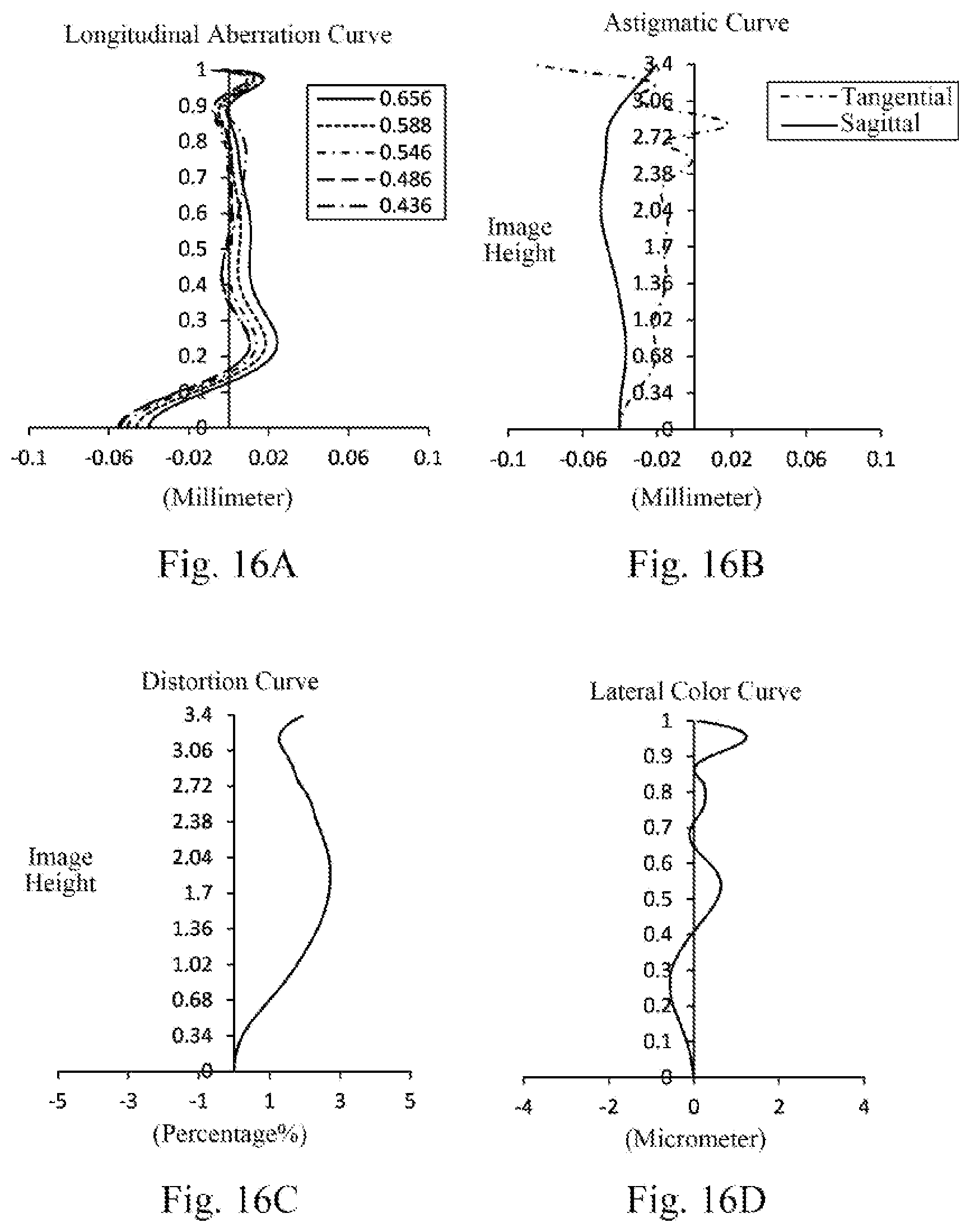
D00013

D00014

D00015
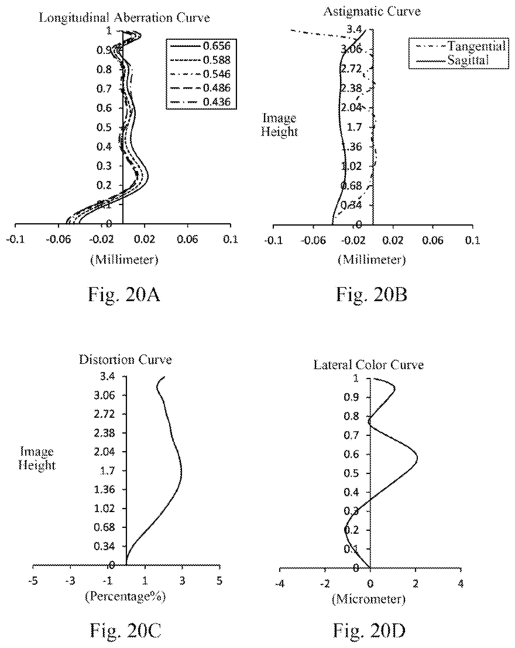
D00016
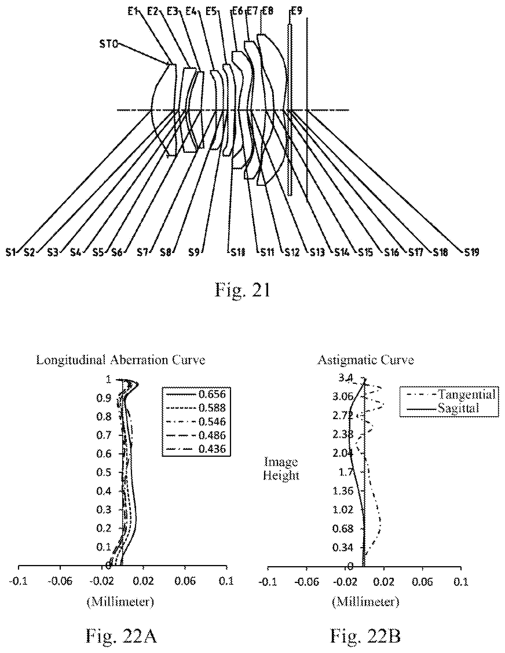
D00017

D00018
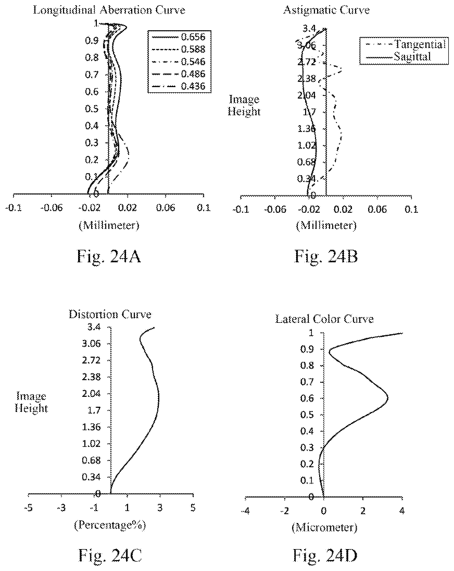

XML
uspto.report is an independent third-party trademark research tool that is not affiliated, endorsed, or sponsored by the United States Patent and Trademark Office (USPTO) or any other governmental organization. The information provided by uspto.report is based on publicly available data at the time of writing and is intended for informational purposes only.
While we strive to provide accurate and up-to-date information, we do not guarantee the accuracy, completeness, reliability, or suitability of the information displayed on this site. The use of this site is at your own risk. Any reliance you place on such information is therefore strictly at your own risk.
All official trademark data, including owner information, should be verified by visiting the official USPTO website at www.uspto.gov. This site is not intended to replace professional legal advice and should not be used as a substitute for consulting with a legal professional who is knowledgeable about trademark law.