Circulating system and a method for continuous downhole cooling of high-temperature drilling fluid
Zhang; Jie ; et al.
U.S. patent application number 17/123123 was filed with the patent office on 2021-04-08 for circulating system and a method for continuous downhole cooling of high-temperature drilling fluid. This patent application is currently assigned to SOUTHWEST PETROLEUM UNIVERSITY. The applicant listed for this patent is SOUTHWEST PETROLEUM UNIVERSITY. Invention is credited to Weilin Chen, Jingbin He, Cuinan Li, Xin Li, Xuefeng Sun, Peigang Wang, Jie Zhang, Zaipeng Zhao.
| Application Number | 20210102441 17/123123 |
| Document ID | / |
| Family ID | 1000005305362 |
| Filed Date | 2021-04-08 |


View All Diagrams
| United States Patent Application | 20210102441 |
| Kind Code | A1 |
| Zhang; Jie ; et al. | April 8, 2021 |
Circulating system and a method for continuous downhole cooling of high-temperature drilling fluid
Abstract
The invention discloses a circulating system and a method for continuous downhole cooling of high-temperature drilling fluid. The circulating system includes a cooling water tank, a cooling water injection pump, a plurality of U-shaped pipes, a liquid nitrogen cooling tank, a spiral pipe, a cooling water return pump and a return pipeline. The U-shaped pipe is fixed in an unsealed bond cement gap between outer and inner casings, and two ends are respectively connected with output end of the cooling water injection pump and the spiral pipe. The spiral pipe is disposed in the liquid nitrogen cooling tank; input and output ends of the cooling water return pump are respectively connected with the spiral pipe and the return pipeline; one end of the return pipeline is disposed in the cooling water tank; input end of the cooling water injection pump is connected with the cooling water tank by a pipe.
| Inventors: | Zhang; Jie; (CHENGDU CITY, CN) ; Li; Xin; (CHENGDU CITY, CN) ; Li; Cuinan; (CHENGDU CITY, CN) ; Zhao; Zaipeng; (CHENGDU CITY, CN) ; Chen; Weilin; (CHENGDU CITY, CN) ; He; Jingbin; (CHENGDU CITY, CN) ; Wang; Peigang; (CHENGDU CITY, CN) ; Sun; Xuefeng; (CHENGDU CITY, CN) | ||||||||||
| Applicant: |
|
||||||||||
|---|---|---|---|---|---|---|---|---|---|---|---|
| Assignee: | SOUTHWEST PETROLEUM
UNIVERSITY CHENGDU CITY CN |
||||||||||
| Family ID: | 1000005305362 | ||||||||||
| Appl. No.: | 17/123123 | ||||||||||
| Filed: | December 16, 2020 |
| Current U.S. Class: | 1/1 |
| Current CPC Class: | E21B 36/001 20130101 |
| International Class: | E21B 36/00 20060101 E21B036/00 |
Foreign Application Data
| Date | Code | Application Number |
|---|---|---|
| Aug 11, 2020 | CN | 202010800147.4 |
Claims
1. A circulating system for continuous downhole cooling of high-temperature drilling fluid, comprising: a cooling water tank, a cooling water injection pump, a plurality of U-shaped pipes, a liquid nitrogen cooling tank, a spiral pipe, a cooling water return pump and a return pipeline; wherein the U-shaped pipes are fixed in an unsealed bond cement gap between an outer casing and an inner casing, and two ends of each of the U-shaped pipes are respectively connected with an output end of the cooling water injection pump and the spiral pipe; the spiral pipe is disposed in the liquid nitrogen cooling tank; an input end and an output end of the cooling water return pump are respectively connected with the spiral pipe and the return pipeline; one end of the return pipeline is disposed in the cooling water tank; an input end of the cooling water injection pump is connected with the cooling water tank by a pipe.
2. The circulating system for continuous downhole cooling of high-temperature drilling fluid according to claim 1, wherein the U-shaped pipe comprises a cooling water insulation pipe connected with the output end of the cooling water injection pump and a heat-carrying cooling water pipe connected with the spiral pipe.
3. The circulating system for continuous downhole cooling of high-temperature drilling fluid according to claim 2, wherein the cooling water insulation pipe is made of thermal insulation material.
4. The circulating system for continuous downhole cooling of high-temperature drilling fluid according to claim 2, wherein a running length of the U-shaped pipe is a length of the inner casing minus a fill-up height of the bond cement, and a diameter of the U-shaped pipe is a radius of the outer casing minus a radius of the inner casing.
5. The circulating system for continuous downhole cooling of high-temperature drilling fluid according to claim 1, wherein a number of U-shaped pipes is eight, and an angle between two adjacent groups of the U-shaped pipes is 45.degree..
6. The circulating system for continuous downhole cooling of high-temperature drilling fluid according to claim 1, wherein the cooling water injection pump and the cooling water return pump are both vane pumps.
7. A method for continuous downhole cooling of high-temperature drilling fluid with a circulating system comprising a cooling water tank, a cooling water injection pump, a plurality of U-shaped pipes, a liquid nitrogen cooling tank, a spiral pipe, a cooling water return pump and a return pipeline, wherein the U-shaped pipes are fixed in an unsealed bond cement gap between an outer casing and an inner casing, and two ends of each of the U-shaped pipes are respectively connected with an output end of the cooling water injection pump and the spiral pipe; the spiral pipe is disposed in the liquid nitrogen cooling tank; an input end and an output end of the cooling water return pump are respectively connected with the spiral pipe and the return pipeline; one end of the return pipeline is disposed in the cooling water tank; an input end of the cooling water injection pump is connected with the cooling water tank by a pipe, the method comprising the following steps: step A: obtaining operating parameters, environmental parameters, well structure parameters and thermal parameters of the target well; step B: placing the U-shaped pipe downward into the unsealed bond cement gap between the outer casing and the inner casing; step C: opening the cooling water injection pump and the cooling water return pump at the same time to make the cooling water flow from wellhead to downhole, and then returning along a heat-carrying cooling water pipe and continuously absorbing heat from the high-temperature drilling fluid in annulus under effect of forced-convection heat transfer and heat conduction, thereby realizing the continuous downhole circulating and cooling of high-temperature drilling fluid in the annulus; step D: calculating a circulating temperature in the drill string, a circulating temperature in the annulus, and a circulating temperature in the heat-carrying cooling water pipe by the following formulas: formula for temperature control in the drill string: .rho. m A pipe c m .differential. T p f .differential. t = - .rho. m A p i p e v p i p e c m .differential. T pf .differential. z + 2 .pi. R p i U a p ( T ann - T pf ) ; ##EQU00009## discrete expression of formula for temperature control in the drill string: B.sub.1(T.sub.pf).sub.i-1.sup.n+1+(A.sub.1-B.sub.1+C.sub.1)(T.sub.pf).sub- .i.sup.n+1=A.sub.1(T.sub.pf).sub.i.sup.n+C.sub.1(T.sub.ann).sub.i.sup.n+1; formula for temperature control in the annulus: .rho. m A ann c m .differential. T a n n .differential. t = .rho. m A a n n v a n n c m .differential. T ann .differential. z - 2 .pi. R c i U c a ( T ann - T c ) - 2 .pi. R pi U a p ( T a n n - T pf ) ; ##EQU00010## discrete expression of formula for temperature control in the annulus: B.sub.2(T.sub.ann).sub.i-1.sup.n+1+(A.sub.2-B.sub.2-C.sub.2-D.sub.2)(T.su- b.ann).sub.i.sup.n+1=A.sub.2(T.sub.ann).sub.i.sup.n-C.sub.2(T.sub.c).sub.i- .sup.n+1-D.sub.2(T.sub.pf).sub.i.sup.n+1; formula for temperature control of the heat-carrying cooling water pipe: .rho. w A c c w .differential. T c .differential. t = .rho. w A c v c c w .differential. T c .differential. z + 2 .pi. R c i U cf ( T f - T c ) + 2 .pi. R c i U c a ( T ann - T c ) ; ##EQU00011## discrete expression of formula for temperature control of the heat-carrying cooling water pipe: B 3 ( T c ) i - 1 n + 1 + ( A 3 - B 3 + C 3 + D 3 ) ( T c ) i n + 1 = A 3 ( T c ) i n + C 3 ( T f ) i n + 1 + D 3 ( T a n n ) i n + 1 ; ##EQU00012## 1 U a p = 1 h p i + R p i R po h po + R p i K pipe ln ( R p o / R p i ) ; ##EQU00012.2## 1 U cf = 1 U c a = 1 h c i + R c i R c o h c o + R c i K c ln ( R c o / R c i ) ; ##EQU00012.3## where, .rho..sub.m and .rho..sub.w are respectively densities of drilling fluid and cooling water, in kg/m.sup.3; c.sub.m and c.sub.w are respectively specific heat capacities of drilling fluid and cooling water, in J/(kg.degree.C.); A.sub.pipe, A.sub.ann and A.sub.c are respectively cross-sectional areas of the drill string, the annulus and the heat-carrying cooling water pipe, in m.sup.2; .nu..sub.pipe, .nu..sub.ann and v.sub.c are respectively flow rates in the drill string, the annulus and the heat-carrying cooling water pipe, in m/s; T.sub.pf, T.sub.ann and T.sub.c are respectively fluid circulating temperatures in the drill string, the annulus and the heat-carrying cooling water pipe, in .degree.C.; R.sub.pi, R.sub.po, R.sub.ci and R.sub.co are respectively the inner radius of drill string, the outer radius of drill string, the inner radius of heat-carrying cooling water pipe and the outer radius of heat-carrying cooling water pipe, in m; h.sub.pi, h.sub.po, h.sub.ci and h.sub.co are respectively convective heat transfer coefficients between the fluid in the drill string and the inner wall of the drill string, the fluid in the annulus and the outer wall of the drill string, the fluid in the heat-carrying cooling water pipe and the inner wall of the heat-carrying cooling water pipe, and the fluid in the heat-carrying cooling water pipe and the well wall, in W/(m.degree.C.); K.sub.pipe and K.sub.c are respectively thermal conductivity of drill string and cooling water heating pipe, in W/(m.degree.C.); A.sub.1, B.sub.1 and C.sub.1 are respectively constants in the formula for temperature control in the drill string; A.sub.2, B.sub.2, C.sub.2 and D.sub.2 are respectively constants in the formula for temperature control in the annulus; A.sub.3, B.sub.3, C.sub.3 and D.sub.3 are respectively constants in the formula for temperature control of the heat-carrying cooling water pipe; step E: adjusting a speed of the cooling water injection pump and the cooling water return pump according to the circulating temperature respectively in the drill string, the annulus and the heat-carrying cooling water pipe obtained above; step F: the cooling water carrying heat flowing into the spiral pipe, and being cooled in the liquid nitrogen cooling tank; and step G: the cooled cooling water being pumped into the return pipe by the cooling water return pump, and being re-injected into the cooling water tank for continued circulating and cooling at the next stage.
Description
TECHNICAL FIELD
[0001] The present invention relates to a circulating system and a method for continuous downhole cooling of high-temperature drilling fluid, belonging to the technical field of continuous downhole cooling of high-temperature drilling fluid.
DESCRIPTION OF PRIO ART
[0002] With the continuous development of the global economy, people's demand for energy is also increasing. In addition to the exploration and development of oil and gas resources, the exploitation of new energy sources such as geothermal resources, dry hot rocks and combustible ice is also gradually increased. However, the high temperature of drilling fluid has always been a key issue affecting the safety and efficiency of well construction in the development both of oil and gas resources and new energy resources. In the deep and ultra-deep wells of oil and gas drilling, the downhole temperature in some areas can be as high as 180.degree. C. In the drilling of geothermal resources and dry hot rocks, the downhole temperature can be as high as 150.degree. C. to 200.degree. C. Excessively high temperature of the drilling fluid will materially affect its own performance, the service life of downhole operating tools and measuring instruments, and the safety of the wellbore, as well as posing a serious threat to the safety, economic effect and efficiency of well construction.
[0003] The existing technologies and equipment for cooling high-temperature drilling fluid mostly adopt ground cooling, that is, reducing the injection temperature of drilling fluid to cool the drilling fluid in the wellbore. However, it is found from the calculation results of relevant theoretical models and the actual application on site that the ground cooling can only reduce the temperature of the drilling fluid in the upper section of the wellbore, while the drilling fluid in the lower section of the wellbore is still at a high temperature. Therefore, the performance of ground cooling is still not ideal when it is used for cooling the high-temperature drilling fluid.
SUMMARY OF THE INVENTION
[0004] The invention proposes a circulating system and a method for continuous downhole cooling of high-temperature drilling fluid to overcomes the shortcomings in the prior art.
[0005] The technical solution provided by the present invention to the above technical problem is: a circulating system for continuous downhole cooling of high-temperature drilling fluid, including a cooling water tank, a cooling water injection pump, a plurality of U-shaped pipes, a liquid nitrogen cooling tank, a spiral pipe, a cooling water return pump and a return pipeline. The U-shaped pipe is fixed in the unsealed bond cement gap between an outer casing and an inner casing, and two ends are respectively connected with the output end of the cooling water injection pump and the spiral pipe; the spiral pipe is disposed in the liquid nitrogen cooling tank; the input and output ends of the cooling water return pump are respectively connected with the spiral pipe and the return pipeline; one end of the return pipeline is disposed in the cooling water tank; the input end of the cooling water injection pump is connected with the cooling water tank by a pipe.
[0006] The volume of the cooling water tank is twice the sum of the volume of all the cooling water insulation pipes to ensure sufficient cooling water injected. The model of the cooling water injection pump is the same as the drilling pump used in drilling.
[0007] The further technical solution is that the U-shaped pipe includes a cooling water insulation pipe connected with the output end of the cooling water injection pump and a heat-carrying cooling water pipe connected with the spiral pipe.
[0008] The further technical solution is that the cooling water insulation pipe is made of thermal insulation material.
[0009] The further technical solution is that a running length of the U-shaped pipe is a length of the inner casing minus the fill-up height of the bond cement, and a diameter is the radius of the outer casing minus the radius of the inner casing.
[0010] The further technical solution is that a number of U-shaped pipes is eight, and an angle between two adjacent groups of U-shaped pipes is 45.degree..
[0011] The further technical solution is that the cooling water injection pump and the cooling water return pump are both vane pumps.
[0012] A method for continuous downhole cooling of high-temperature drilling fluid with the above circulating system, including the following steps:
[0013] step A: obtaining operating parameters, environmental parameters, well structure parameters and thermal parameters of the target well;
[0014] step B: placing the U-shaped pipe downward into the unsealed bond cement gap between the outer and inner casings;
[0015] step C: opening the cooling water injection pump and the cooling water return pump at the same time to make the cooling water flow from wellhead to downhole, and then returning along the heat-carrying cooling water pipe and continuously absorbing heat from the high-temperature drilling fluid in the annulus under the effect of forced-convection heat transfer and heat conduction, thereby realizing the continuous downhole circulating and cooling of high-temperature drilling fluid in the annulus;
[0016] step D: calculating a circulating temperature in the drill string, a circulating temperature in the annulus, and a circulating temperature in the heat-carrying cooling water pipe by the following formulas:
[0017] Formula for temperature control in the drill string:
.rho. m A pipe c m .differential. T p f .differential. t = - .rho. m A pipe v pipe c m .differential. T p f .differential. z + 2 .pi. R p i U a p ( T ann - T pf ) . ##EQU00001##
[0018] Discrete expression of formula for temperature control in the drill string:
B.sub.1(T.sub.pf).sub.i-1.sup.n+1+(A.sub.1-B.sub.1+C.sub.1)(T.sub.pf).su- b.i.sup.n+1=A.sub.1(T.sub.pf).sub.i.sup.n+C.sub.1(T.sub.ann).sub.i.sup.n+1- .
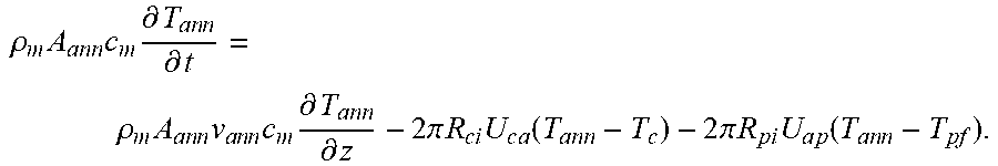
[0019] Formula for temperature control in the annulus:
.rho. m A ann c m .differential. T a n n .differential. t = .rho. m A a n n v a n n c m .differential. T ann .differential. z - 2 .pi. R c i U ca ( T ann - T c ) - 2 .pi. R pi U a p ( T a n n - T pf ) . ##EQU00002##
[0020] Discrete expression of formula for temperature control in the annulus:
B.sub.2(T.sub.ann).sub.i-1.sup.n+1+(A.sub.2-B.sub.2-C.sub.2-D.sub.2)(T.s- ub.ann).sub.i.sup.n+1=A.sub.2(T.sub.ann).sub.i.sup.n-C.sub.2(T.sub.c).sub.- i.sup.n+1-D.sub.2(T.sub.pf).sub.i.sup.n+1.
[0021] Formula for temperature control of the heat-carrying cooling water pipe:
.rho. w A c c w .differential. T c .differential. t = .rho. w A c v c c w .differential. T c .differential. z + 2 .pi. R c i U cf ( T f - T c ) + 2 .pi. R c i U c a ( T ann - T c ) . ##EQU00003##
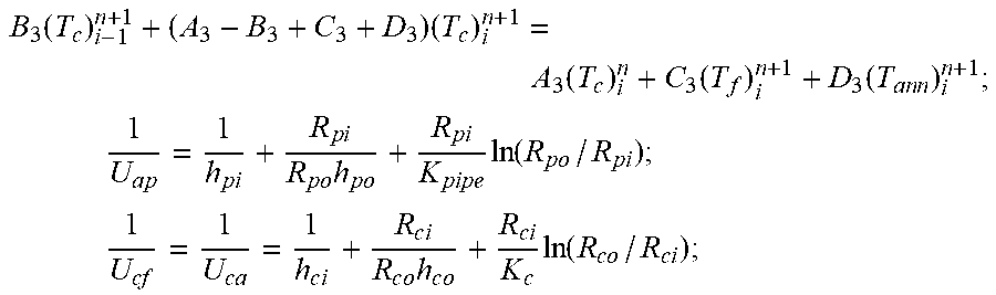
[0022] Discrete expression of formula for temperature control of the heat-carrying cooling water pipe:
B 3 ( T c ) i - 1 n + 1 + ( A 3 - B 3 + C 3 + D 3 ) ( T c ) i n + 1 = A 3 ( T c ) i n + C 3 ( T f ) i n + 1 + D 3 ( T a n n ) i n + 1 ; ##EQU00004## 1 U ap = 1 h p i + R p i R po h po + R p i K pipe ln ( R po / R pi ) ; ##EQU00004.2## 1 U cf = 1 U c a = 1 h c i + R c i R co h c o + R c i K c ln ( R c o / R c i ) . ##EQU00004.3##
[0023] Where, .rho..sub.m and .rho..sub.w are respectively the densities of drilling fluid and cooling water, in kg/m.sup.3; c.sub.m and c.sub.w are respectively specific heat capacities of drilling fluid and cooling water, in J/(kg.degree.C).; A.sub.pipe A.sub.ann and A.sub.c are respectively cross-sectional areas of the drill string, the annulus and the heat-carrying cooling water pipe, in m.sup.2; .nu..sub.pipe, .nu..sub.ann and .nu..sub.c are respectively flow rates in drill string, annulus and heat-carrying cooling water pipe, in m/s; T.sub.pfT.sub.ann and T.sub.c are respectively fluid circulating temperatures in drill string, annulus and heat-carrying cooling water pipe, in .degree.C.; R.sub.pi, R.sub.po, R.sub.ci and R.sub.co are respectively the inner radius of drill string, the outer radius of drill string, the inner radius of heat-carrying cooling water pipe and the outer radius of heat-carrying cooling water pipe, in m; h.sub.pi, h.sub.po, h.sub.ci and h.sub.co are respectively convective heat transfer coefficient between the fluid in the drill string and the inner wall of the drill string, the fluid in the annulus and the outer wall of the drill string, the fluid in the heat-carrying cooling water pipe and the inner wall of the heat-carrying cooling water pipe, and the fluid in the heat-carrying cooling water pipe and the well wall, in W/(m.degree.C.); K.sub.pipe and K.sub.c are respectively thermal conductivities of drill string and cooling water heating pipe, in W/(m.degree.C.); A.sub.1, B.sub.1 and C.sub.1 are respectively constants in the formula for temperature control in the drill string; A.sub.2, B.sub.2, C.sub.2 and D.sub.2 are respectively constants in the formula for temperature control in the annulus; A.sub.3, B.sub.3, C.sub.3 and D.sub.3 are respectively constants in the formula for temperature control of the heat-carrying cooling water pipe;
[0024] step E: adjusting a speed of the cooling water injection pump and the cooling water return pump according to the circulating temperature respectively in the drill string, the annulus and the heat-carrying cooling water pipe obtained above;
[0025] step F: the cooling water carrying heat flowing into the spiral pipe, and being cooled in the liquid nitrogen cooling tank; and
[0026] step G: the cooled cooling water being pumped into the return pipe by the cooling water return pump, and being re-injected into the cooling water tank for continued circulating and cooling at the next stage.
[0027] The present invention has the following beneficial effects:
[0028] (1) the present invention makes full use of the unsealed bond cement gap between the two casings, and adopts the method of injecting cooling water into downhole to directly cool down the high-temperature drilling fluid in the circulating process continuously;
[0029] (2) the present invention makes full use of the small gap between the two casings to directly reinforce the cooling water insulation pipe and the heat-carrying cooling water pipe the run into the well without installing additional reinforcement equipment, which is convenient and reliable for run-in and installation; and
[0030] (3) the present invention adopts a closed-loop circulating method to cool down the heat-carrying cooling water returned to the ground and then pump it into the cooling water tank again for continued circulating and cooling at the next stage, so as to make full utilization of previous water resources.
BRIEF DESCRIPTION OF THE DRAWINGS
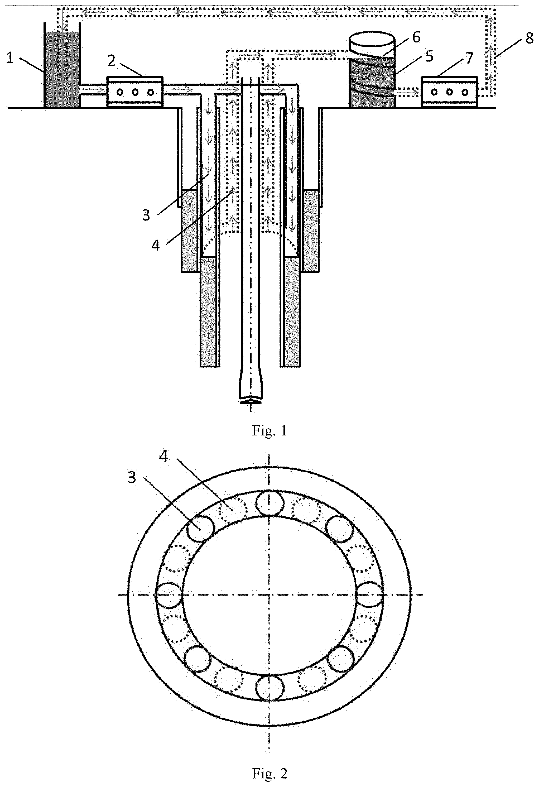
[0031] FIG. 1 is a schematic diagram of system composition of the present invention;
[0032] FIG. 2 is a top view of the wellhead of the present invention; and
[0033] FIG. 3 is a calculation diagram of the embodiment.
DETAILED DESCRIPTION OF THE PREFERRED EMBODIMENTS
[0034] The present invention will be further described with the following embodiments and figures.
[0035] As shown in FIG. 1 and FIG. 2, a circulating system for continuous downhole cooling of high-temperature drilling fluid is provided in the present invention, including a cooling water tank 1, a cooling water injection pump 2, eight U-shaped pipes, a liquid nitrogen cooling tank 5, a spiral pipe 6, a cooling water return pump 7 and a return pipeline 8. The eight U-shaped pipes are respectively fixed in the unsealed bond cement gap between the outer and inner casings. The angle between two adjacent groups of U-shaped pipes is 45.degree. to avoid the heat exchange, which will affect the overall cooling effect, between the two groups of U-shaped pipes, and two ends of the U-shaped pipe are respectively connected with the output end of the cooling water injection pump 2 and the spiral pipe 6. The spiral pipe 6 is disposed in the liquid nitrogen cooling tank 5. The spiral pipe 6 increases the flow path of heat-carrying cooling water in the liquid nitrogen cooling tank 5, and prolongs the heat exchange between the heat-carrying cooling water and the external liquid nitrogen. There is full of liquid nitrogen outside of the pipe, so it is easy to cool the heat-carrying cooling water due to the feature that liquid nitrogen is easy to absorb heat and sublimate.
[0036] The input end and the output end of the cooling water return pump 7 are respectively connected with the spiral pipe 6 and the return pipeline 8. One end of the return pipeline 8 is disposed in the cooling water tank 1. The input end of the cooling water injection pump 2 is connected with the cooling water tank 1 by a pipe.
[0037] The process and principles of the present invention for continuous downhole cooling of the high-temperature drilling fluid are described as follows:
[0038] (1) In actual cooling process, the cooling water injection pump continuously pumps the cooling water into the cooling water insulation pipe from the cooling water tank.
[0039] (2) Due to the insulation effect of the cooling water insulation pipe, the cooling water will not exchange heat with the high-temperature drilling fluid in the annulus when it flows from the wellhead to the bottom of the well. The temperature of the cooling water is always maintained at the temperature when it enters the inlet. In the process of returning along the heat-carrying cooling water pipe, the cooling water will continuously absorb heat from the high-temperature drilling fluid in the annulus through convective heat exchange and heat conduction, thereby achieving continuous downhole cooling of the high-temperature drilling fluid in the annulus. After the drilling fluid in the annulus is cooled by the cooling water, the heat transferred to the drilling fluid in the drill string is reduced, thus further realizing continuous downhole cooling of the high-temperature drilling fluid in the drill string.
[0040] After the drilling fluid in the drill string is cooled, the temperature of the drilling fluid flowing into the annulus will also decrease, that is to say, the high-temperature drilling fluid in the annulus which is not in contact with the heat-carrying cooling water pipe will be continuously cooled.
[0041] (3) After being heated, the cooling water will return to the liquid nitrogen cooling tank on the ground. After the carrying-heat cooling water flows into the liquid nitrogen cooling tank, it will flow along the spiral pipe in the tank to the liquid outlet. When the heat-carrying cooling water flows, the liquid nitrogen outside the pipe will be heated and sublimated, so as to cool the heat-carrying cooling water in the spiral pipe.
[0042] (4) The cooled cooling water will be pumped into the return pipe by the cooling water return pump, and re-injected into the cooling water tank for continued circulating and cooling at the next stage.
[0043] As shown in FIG. 1, the U-shaped pipe in this embodiment includes the cooling water insulation pipe 3 connected with the output end of the cooling water injection pump 2 and the heat-carrying cooling water pipe 4 connected with the spiral pipe 6. The cooling water insulation pipe 3 is made of thermal insulation material to ensure that the cooling water will not be heated by the high-temperature drilling fluid in the annulus when it flows from the wellhead to the bottom of the well. The heat-carrying cooling water pipe 4 is made of the material as the same as that of the casing, which enhances the heat exchange between the cooling water and the high-temperature drilling fluid in the annulus during the upward return process. The running length of the U-shaped pipe is the length of the inner casing minus the fill-up height of the bond cement and the diameter is the radius of the outer casing minus the radius of the inner casing.
[0044] The cooling water injection pump 2 and cooling water return pump 7 in this embodiment are specifically both vane pumps.
[0045] The method for continuous downhole cooling of high-temperature drilling fluid using above embodiments, including the following steps:
[0046] Step A: obtaining operating parameters, environmental parameters, well structure parameters and thermal parameters of the target well.
[0047] Step B: placing the U-shaped pipe downward into the unsealed bond cement gap between the outer and inner casings.
[0048] Step C: opening the cooling water injection pump 2 and the cooling water return pump 7 at the same time to make the cooling water injection pump 2 continuously pump the cooling water in the cooling water tank 1 into the cooling water insulation pipe 3 and to make the cooling water flow from wellhead to downhole, and then returning along the heat-carrying cooling water pipe 4 and continuously absorbing heat from the high-temperature drilling fluid in the annulus under the effect of forced-convection heat transfer and heat conduction, thereby realizing the continuous downhole circulating and cooling of high-temperature drilling fluid in the annulus.
[0049] Step D: calculating the circulating temperature in the drill string, the circulating temperature in the annulus, and the circulating temperature in the heat-carrying cooling water pipe by the following formulas.
[0050] Formula for temperature control in the drill string:
.rho. m A pipe c m .differential. T pf .differential. t = - .rho. m A pipe v pipe c m .differential. T pf .differential. z + 2 .pi. R p i U a p ( T ann - T pf ) . ##EQU00005##
[0051] Discrete expression of formula for temperature control in the drill string:
B.sub.i(T.sub.pf).sub.i-1.sup.n+1+(A.sub.1-B.sub.1+C.sub.1)(T.sub.pf).su- b.i.sup.n+1=A.sub.1(T.sub.pf).sub.i.sup.n=C.sub.1(T.sub.ann).sub.i.sup.n+1- .
[0052] Formula for temperature control in the annulus:
.rho. m A ann c m .differential. T a n n .differential. t = .rho. m A a n n v a n n c m .differential. T ann .differential. z - 2 .pi. R c i U c a ( T ann - T c ) - 2 .pi. R pi U a p ( T a n n - T pf ) . ##EQU00006##
[0053] Discrete expression of formula for temperature control in the annulus:
B.sub.2(T.sub.ann).sub.i-1.sup.n+1+(A.sub.2-B.sub.2-C.sub.2-D.sub.2)(T.s- ub.ann).sub.i.sup.n+1=A.sub.2(T.sub.ann).sub.i.sup.n-C.sub.2(T.sub.c).sub.- i.sup.n+1-D.sub.2(T.sub.pf).sub.i.sup.n+1.
[0054] Formula for temperature control of the heat-carrying cooling water pipe:
.rho. w A c c w .differential. T c .differential. t = .rho. w A c v c c w .differential. T c .differential. z + 2 .pi. R c i U cf ( T f - T c ) + 2 .pi. R c i U c a ( T ann - T c ) . ##EQU00007##
[0055] Discrete expression of formula for temperature control of the heat-carrying cooling water pipe:
B 3 ( T c ) i - 1 n + 1 + ( A 3 - B 3 + C 3 + D 3 ) ( T c ) i n + 1 = A 3 ( T c ) i n + C 3 ( T f ) i n + 1 + D 3 ( T a n n ) i n + 1 ; ##EQU00008## 1 U a p = 1 h p i + R p i R p o h po + R p i K pipe ln ( R po / R pi ) ; ##EQU00008.2## 1 U cf = 1 U c a = 1 h c i + R c i R c o h c o + R c i K c ln ( R c o / R c i ) . ##EQU00008.3##
[0056] Where, .rho..sub.m and .rho..sub.w are respectively densities of drilling fluid and cooling water, in kg/m.sup.3; c.sub.m and c.sub.w are respectively specific heat capacities of drilling fluid and cooling water, in J/(kg.degree.C.); A.sub.pipe, A.sub.ann and A.sub.c are respectively cross-sectional areas of drill string, annulus and heat-carrying cooling water pipe, in m.sup.2; .nu..sub.pipe, .nu..sub.ann, and .nu..sub.c are respectively flow rates in drill string, annulus and heat-carrying cooling water pipe, in m/s; T.sub.pf, T.sub.ann and T.sub.c are respectively fluid circulating temperatures s in drill string, annulus and heat-carrying cooling water pipe, in .degree.C.; R.sub.pi, R.sub.po, R.sub.ci and R.sub.co are respectively the inner radius of drill string, the outer radius of drill string, the inner radius of heat-carrying cooling water pipe and the outer radius of heat-carrying cooling water pipe, in m; h.sub.pi, h.sub.p0, h.sub.ci and h.sub.co are respectively the convective heat transfer coefficients between the fluid in the drill string and the inner wall of the drill string, the fluid in the annulus and the outer wall of the drill string, the fluid in the heat-carrying cooling water pipe and the inner wall of the heat-carrying cooling water pipe, and the fluid in the heat-carrying cooling water pipe and the well wall, in W/(m.degree.C.); K.sub.pipe and K.sub.c are respectively thermal conductivities of drill string and cooling water heating pipe, in W/(m.degree.C.); A.sub.1, B.sub.1 and C.sub.1 are respectively constants in the formula for temperature control in the drill string; A.sub.2, B.sub.2, C.sub.2 and D.sub.2 are respectively constants in the formula for temperature control in the annulus; A.sub.3, B.sub.3, C.sub.3 and D.sub.3 are respectively constants in the formula for temperature control of the heat-carrying cooling water pipe.
[0057] Step E: adjusting a speed of the cooling water injection pump 2 and the cooling water return pump 7 according to the circulating temperature respectively in the drill string, the annulus and the heat-carrying cooling water pipe obtained above.
[0058] Step F: the cooling water carrying heat flowing into the spiral pipe 6, and being cooled in the liquid nitrogen cooling tank 5.
[0059] Step G: the cooled cooling water being pumped into the return pipe 8 by the cooling water return pump 7, and being re-injected into the cooling water tank 1 for continued circulating and cooling at the next stage.
[0060] In the above embodiment, the displacement of the drilling pump is 40 L/s, and the displacements of the cooling water injection pump are 10 L/s, 20 L/s, and 30 L/s, respectively. The calculation results are shown in FIG. 3. Learned from the figure, it can be found that when the displacement of the cooling water injection pump is 20 L/s (1/2 of the drilling pump's displacement), the relative flow of the cooling water in the heat-carrying pipe and the high-temperature drilling fluid in the annulus is more uniform, and the cooling effect is the best.
[0061] The above are not intended to limit the present invention in any form. Although the present invention has been disclosed as above with embodiments, it is not intended to limit the present invention. Those skilled in the art, within the scope of the technical solution of the present invention, can use the disclosed technical content to make a few changes or modify the equivalent embodiment with equivalent changes. Within the scope of the technical solution of the present invention, any simple modification, equivalent change and modification made to the above embodiments according to the technical essence of the present invention are still regarded as a part of the technical solution of the present invention.
* * * * *
D00000
D00001
D00002


XML
uspto.report is an independent third-party trademark research tool that is not affiliated, endorsed, or sponsored by the United States Patent and Trademark Office (USPTO) or any other governmental organization. The information provided by uspto.report is based on publicly available data at the time of writing and is intended for informational purposes only.
While we strive to provide accurate and up-to-date information, we do not guarantee the accuracy, completeness, reliability, or suitability of the information displayed on this site. The use of this site is at your own risk. Any reliance you place on such information is therefore strictly at your own risk.
All official trademark data, including owner information, should be verified by visiting the official USPTO website at www.uspto.gov. This site is not intended to replace professional legal advice and should not be used as a substitute for consulting with a legal professional who is knowledgeable about trademark law.