Aerosolizable Structure
ABI AOUN; Walid ; et al.
U.S. patent application number 15/733194 was filed with the patent office on 2021-04-08 for aerosolizable structure. The applicant listed for this patent is NICOVENTURES TRADING LIMITED. Invention is credited to Walid ABI AOUN, Andy DAVIS, Glen ELGAR.
| Application Number | 20210100281 15/733194 |
| Document ID | / |
| Family ID | 1000005313940 |
| Filed Date | 2021-04-08 |

| United States Patent Application | 20210100281 |
| Kind Code | A1 |
| ABI AOUN; Walid ; et al. | April 8, 2021 |
AEROSOLIZABLE STRUCTURE
Abstract
Disclosed is an aerosolizable structure for use in an article for use with apparatus for heating aerosolizable material to volatilize at least one component of the aerosolizable material. The aerosolizable structure includes a gathered layered structure having a first sheet including aerosolizable material and a second sheet including heating material that is heatable by penetration with a varying magnetic field to heat the aerosolizable material of the first sheet. The second sheet is free from aerosolizable material.
| Inventors: | ABI AOUN; Walid; (London, GB) ; ELGAR; Glen; (London, GB) ; DAVIS; Andy; (London, GB) | ||||||||||
| Applicant: |
|
||||||||||
|---|---|---|---|---|---|---|---|---|---|---|---|
| Family ID: | 1000005313940 | ||||||||||
| Appl. No.: | 15/733194 | ||||||||||
| Filed: | December 6, 2018 | ||||||||||
| PCT Filed: | December 6, 2018 | ||||||||||
| PCT NO: | PCT/EP2018/083795 | ||||||||||
| 371 Date: | June 8, 2020 |
| Current U.S. Class: | 1/1 |
| Current CPC Class: | A24C 5/01 20200101; A24D 1/20 20200101; A24F 40/20 20200101; A24F 40/465 20200101; A24B 3/14 20130101 |
| International Class: | A24D 1/20 20060101 A24D001/20; A24F 40/20 20060101 A24F040/20; A24F 40/465 20060101 A24F040/465; A24C 5/01 20060101 A24C005/01; A24B 3/14 20060101 A24B003/14 |
Foreign Application Data
| Date | Code | Application Number |
|---|---|---|
| Dec 8, 2017 | GB | 1720535.2 |
Claims
1. An aerosolizable structure for use in an article for use with an apparatus for heating aerosolizable material to volatilize at least one component of the aerosolizable material, the aerosolizable structure comprising: a gathered layered structure comprising: a first sheet comprising aerosolizable material; and a second sheet comprising heating material that is heatable by penetration with a varying magnetic field to heat the aerosolizable material of the first sheet, wherein the second sheet is free from aerosolizable material.
2. The aerosolizable structure of claim 1, wherein the aerosolizable material is reconstituted, cellulosic, or in gel form.
3. The aerosolizable structure of claim 2, wherein the aerosolizable structure is free from any aerosolizable material between the heating material and the reconstituted or cellulosic aerosolizable material or the aerosolizable material in gel form.
4. The aerosolizable structure of claim 2, wherein the reconstituted or cellulosic aerosolizable material or the aerosolizable material in gel form is in surface contact with the heating material.
5. An aerosolizable structure for use in an article for use with apparatus for heating aerosolizable material to volatilize at least one component of the aerosolizable material, the aerosolizable structure comprising: a gathered layered structure comprising: a first sheet comprising aerosolizable material; a second sheet comprising heating material; and a third sheet comprising aerosolizable material; wherein the second sheet is located between the first sheet and the third sheet, and wherein the heating material is heatable by penetration with a varying magnetic field to heat the aerosolizable material of the first sheet and the third sheet.
6. The aerosolizable structure of claim 5, wherein the second sheet is free from aerosolizable material.
7. The aerosolizable structure of claim 1, wherein the gathered layered structure is crimped.
8. The aerosolizable structure of claim 1, claims 1 to 7, wherein the heating material comprises one or more materials selected from the group consisting of: an electrically-conductive material, a magnetic material, and a magnetic electrically-conductive material.
9. The aerosolizable structure of claim 1, wherein the heating material comprises a metal or a metal alloy.
10. The aerosolizable structure of claim 1, wherein the heating material comprises one or more materials selected from the group consisting of: aluminum, gold, iron, nickel, cobalt, conductive carbon, graphite, steel, plain-carbon steel, mild steel, stainless steel, ferritic stainless steel, copper, and bronze.
11. The aerosolizable structure of any one of claims 1 to 10, wherein the first sheet comprises reconstituted tobacco.
12. The aerosolizable structure of claim 1, wherein the second sheet comprises aluminum aluminium foil.
13. The aerosolizable structure of claim 1, comprising a wrapper wrapped around the gathered layered structure.
14. The aerosolizable structure of claim 1, wherein the aerosolizable structure is substantially cylindrical.
15. An article for use with an apparatus for heating aerosolizable material to volatilize at least one component of the aerosolizable material, the article comprising the aerosolizable structure of claim 1.
16. The article of claim 15, comprising a filter for filtering aerosol released from the aerosolizable structure in use, and a connector by which the filter is retained relative to the aerosolizable structure.
17. A system for heating aerosolizable material to volatilize at least one component of the aerosolizable material, the system comprising: the article according to claim 15; and an apparatus for heating the aerosolizable material of the article to volatilize at least one component of the aerosolizable material, the apparatus comprising: a heating zone for receiving the article, and a magnetic field generator for generating the varying magnetic field for penetrating the heating material of the article when the article is located in the heating zone.
18. A method of manufacturing an aerosolizable structure for use in an article for use with apparatus for heating aerosolizable material to volatilize at least one component of the aerosolizable material, the method comprising: providing a layered structure, the layered structure having a first sheet comprising aerosolizable material, and a second sheet comprising heating material that is heatable by penetration with a varying magnetic field to heat the aerosolizable material; and gathering the layered structure to form a gathered layered structure.
19. The method of claim 18, wherein the second sheet is free from aerosolizable material.
20. The method of claim 18, wherein the layered structure has a third sheet comprising aerosolizable material, wherein the second sheet is located between the first sheet and the third sheet, and wherein the heating material is heatable by penetration with a varying magnetic field to heat the aerosolizable material of the first sheet and the third sheet.
21. The method of claim 18, wherein the gathering comprises feeding the layered structure through a converging funnel.
22. The method of claim 18, wherein the gathering causes the layered structure to become substantially cylindrical.
23. The method of claim 18, comprising crimping the layered structure before the gathering.
24. The method of claim 18, wherein providing the layered structure comprises causing the first sheet to come into contact with the second sheet.
25. The method of claim 18, comprising wrapping a wrapper around the gathered layered structure to form a wrapped gathered layered structure.
26. The method of claim 25, comprising severing the wrapped gathered layered structure to form a discrete wrapped gathered layered structure.
27. A method of manufacturing an article for use with an apparatus for heating aerosolizable material to volatilize at least one component of the aerosolizable material, the method comprising: performing the method of claim 18; and connecting a filter to the gathered layered structure using a connector that retains the filter relative to the gathered layered structure.
Description
PRIORITY CLAIM
[0001] The present application is a National Phase entry of PCT Application No. PCT/EP2018/083795, filed Dec. 6, 2018, which claims priority from GB Patent Application No. 1720535.2, filed Dec. 8, 2017, each of which is hereby fully incorporated herein by reference.
TECHNICAL FIELD
[0002] The present disclosure relates to aerosolizable structures for use in articles for use with apparatus for heating aerosolizable material, methods of manufacturing an aerosolizable structure, articles for use with apparatus for heating aerosolizable material, methods of manufacturing an article for use with apparatus for heating aerosolizable material, and systems comprising such an article and such apparatus.
BACKGROUND
[0003] Smoking articles such as cigarettes, cigars and the like burn tobacco during use to create tobacco smoke. Attempts have been made to provide alternatives to these articles by creating products that release compounds without combusting. Examples of such products are so-called "heat not burn" products or tobacco heating devices or products, which release compounds by heating, but not burning, material. The material may be, for example, tobacco or other non-tobacco products, which may or may not contain nicotine.
SUMMARY
[0004] A first aspect of the present disclosure provides an aerosolizable structure for use in an article for use with apparatus for heating aerosolizable material to volatilize at least one component of the aerosolizable material, the aerosolizable structure comprising: a gathered layered structure having: a first sheet comprising aerosolizable material; and a second sheet comprising heating material that is heatable by penetration with a varying magnetic field to heat the aerosolizable material of the first sheet, wherein the second sheet is free from aerosolizable material.
[0005] In an exemplary embodiment, the aerosolizable material is reconstituted, cellulosic, or in gel form.
[0006] In an exemplary embodiment, the aerosolizable structure is free from any aerosolizable material between the heating material and the reconstituted or cellulosic aerosolizable material or the aerosolizable material in gel form.
[0007] In an exemplary embodiment, the reconstituted or cellulosic aerosolizable material or the aerosolizable material in gel form is in surface contact with the heating material.
[0008] In an exemplary embodiment, the second sheet consists of the heating material only.
[0009] In an exemplary embodiment, the layered structure is crimped.
[0010] In an exemplary embodiment, the heating material comprises one or more materials selected from the group consisting of: an electrically-conductive material, a magnetic material, and a magnetic electrically-conductive material.
[0011] In an exemplary embodiment, the heating material comprises a metal or a metal alloy.
[0012] In an exemplary embodiment, the heating material comprises one or more materials selected from the group consisting of: aluminum, gold, iron, nickel, cobalt, conductive carbon, graphite, steel, plain-carbon steel, mild steel, stainless steel, ferritic stainless steel, copper, and bronze.
[0013] In an exemplary embodiment, the first sheet comprises reconstituted tobacco.
[0014] In an exemplary embodiment, the second sheet comprises aluminium foil.
[0015] In an exemplary embodiment, the aerosolizable structure comprises a wrapper wrapped around the gathered layered structure.
[0016] In an exemplary embodiment, the aerosolizable structure is substantially cylindrical.
[0017] A second aspect of the present disclosure provides an aerosolizable structure for use in an article for use with apparatus for heating aerosolizable material to volatilize at least one component of the aerosolizable material, the aerosolizable structure comprising: a gathered layered structure having: a first sheet comprising aerosolizable material; a second sheet comprising heating material; and a third sheet comprising aerosolizable material; wherein the second sheet is located between the first and third sheets, and wherein the heating material is heatable by penetration with a varying magnetic field to heat the aerosolizable material of the first and third sheets.
[0018] In an exemplary embodiment, the second sheet is free from aerosolizable material.
[0019] In an exemplary embodiment, the second sheet consists of the heating material only.
[0020] In an exemplary embodiment, the layered structure is crimped.
[0021] In an exemplary embodiment, the heating material comprises one or more materials selected from the group consisting of: an electrically-conductive material, a magnetic material, and a magnetic electrically-conductive material.
[0022] In an exemplary embodiment, the heating material comprises a metal or a metal alloy.
[0023] In an exemplary embodiment, the heating material comprises one or more materials selected from the group consisting of: aluminum , gold, iron, nickel, cobalt, conductive carbon, graphite, steel, plain-carbon steel, mild steel, stainless steel, ferritic stainless steel, copper, and bronze.
[0024] In an exemplary embodiment, the aerosolizable material of the first sheet is reconstituted, cellulosic, or in gel form.
[0025] In an exemplary embodiment, the first sheet comprises reconstituted tobacco.
[0026] In an exemplary embodiment, the second sheet comprises aluminum foil.
[0027] In an exemplary embodiment, the aerosolizable material of the third sheet is reconstituted, cellulosic, or in gel form.
[0028] In an exemplary embodiment, the third sheet comprises reconstituted tobacco.
[0029] In an exemplary embodiment, the aerosolizable structure comprises a wrapper wrapped around the gathered layered structure.
[0030] In an exemplary embodiment, the aerosolizable structure is substantially cylindrical.
[0031] A third aspect of the present disclosure provides an article for use with apparatus for heating aerosolizable material to volatilize at least one component of the aerosolizable material, the article comprising the aerosolizable structure of the first aspect of the present disclosure or the aerosolizable structure of the second aspect of the present disclosure.
[0032] In an exemplary embodiment, the article comprises a filter for filtering aerosol released from the aerosolizable structure in use, and a connector by which the filter is retained relative to the aerosolizable structure.
[0033] A fourth aspect of the present disclosure provides a system for heating aerosolizable material to volatilize at least one component of the aerosolizable material, the system comprising: an article according to the third aspect of the present disclosure; and apparatus for heating the aerosolizable material of the article to volatilize at least one component of the aerosolizable material, the apparatus comprising: a heating zone for receiving the article, and a magnetic field generator for generating the varying magnetic field for penetrating the heating material of the article when the article is located in the heating zone.
[0034] A fifth aspect of the present disclosure provides a method of manufacturing an aerosolizable structure for use in an article for use with apparatus for heating aerosolizable material to volatilize at least one component of the aerosolizable material, the method comprising: providing a layered structure, the layered structure having a first sheet comprising aerosolizable material, and a second sheet comprising heating material that is heatable by penetration with a varying magnetic field to heat the aerosolizable material; and gathering the layered structure to form a gathered layered structure.
[0035] In an exemplary embodiment, the second sheet is free from aerosolizable material.
[0036] In an exemplary embodiment, the second sheet consists of the heating material only.
[0037] In an exemplary embodiment, the second sheet comprises aluminum foil.
[0038] In an exemplary embodiment, the aerosolizable material of the first sheet is reconstituted, cellulosic, or in gel form.
[0039] In an exemplary embodiment, the first sheet comprises reconstituted tobacco.
[0040] In an exemplary embodiment, the layered structure has a third sheet comprising aerosolizable material, the second sheet is located between the first and third sheets, and the heating material is heatable by penetration with a varying magnetic field to heat the aerosolizable material of the first and third sheets.
[0041] In an exemplary embodiment, the aerosolizable material of the third sheet is reconstituted, cellulosic, or in gel form.
[0042] In an exemplary embodiment, the third sheet comprises reconstituted tobacco.
[0043] In an exemplary embodiment, the gathering comprises feeding the layered structure through a converging funnel.
[0044] In an exemplary embodiment, the gathering causes the layered structure to become substantially cylindrical.
[0045] In an exemplary embodiment, the method comprises crimping the layered structure before the gathering.
[0046] In an exemplary embodiment, the providing the layered structure comprises causing the first sheet to come into contact with the second sheet.
[0047] In an exemplary embodiment, the providing the layered structure comprises causing the third sheet to come into contact with the second sheet.
[0048] In an exemplary embodiment, the method comprises wrapping a wrapper around the gathered layered structure to form a wrapped gathered layered structure.
[0049] In an exemplary embodiment, the method comprises severing the wrapped gathered layered structure to form a discrete wrapped gathered layered structure.
[0050] A sixth aspect of the present disclosure provides a method of manufacturing an article for use with apparatus for heating aerosolizable material to volatilize at least one component of the aerosolizable material, the method comprising: performing the method of the fifth aspect of the present disclosure; and connecting a filter to the gathered layered structure using a connector that retains the filter relative to the gathered layered structure.
BRIEF DESCRIPTION OF THE DRAWINGS
[0051] Embodiments of the disclosure will now be described, by way of example only, with reference to the accompanying drawings, in which:
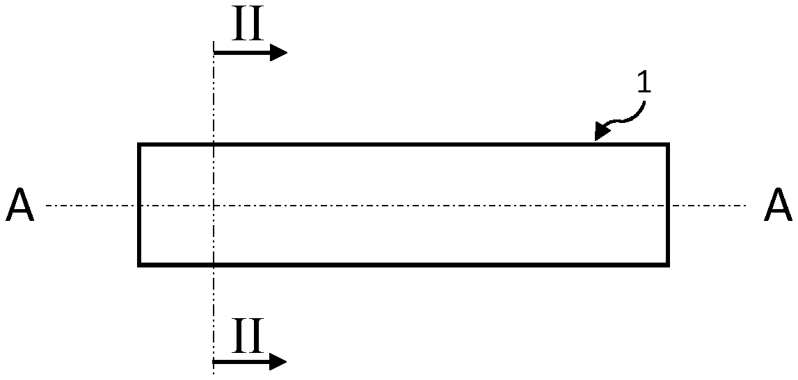
[0052] FIG. 1 shows a schematic side view of an example of an aerosolizable structure for use in an article for use with apparatus for heating aerosolizable material to volatilize at least one component of the aerosolizable material.
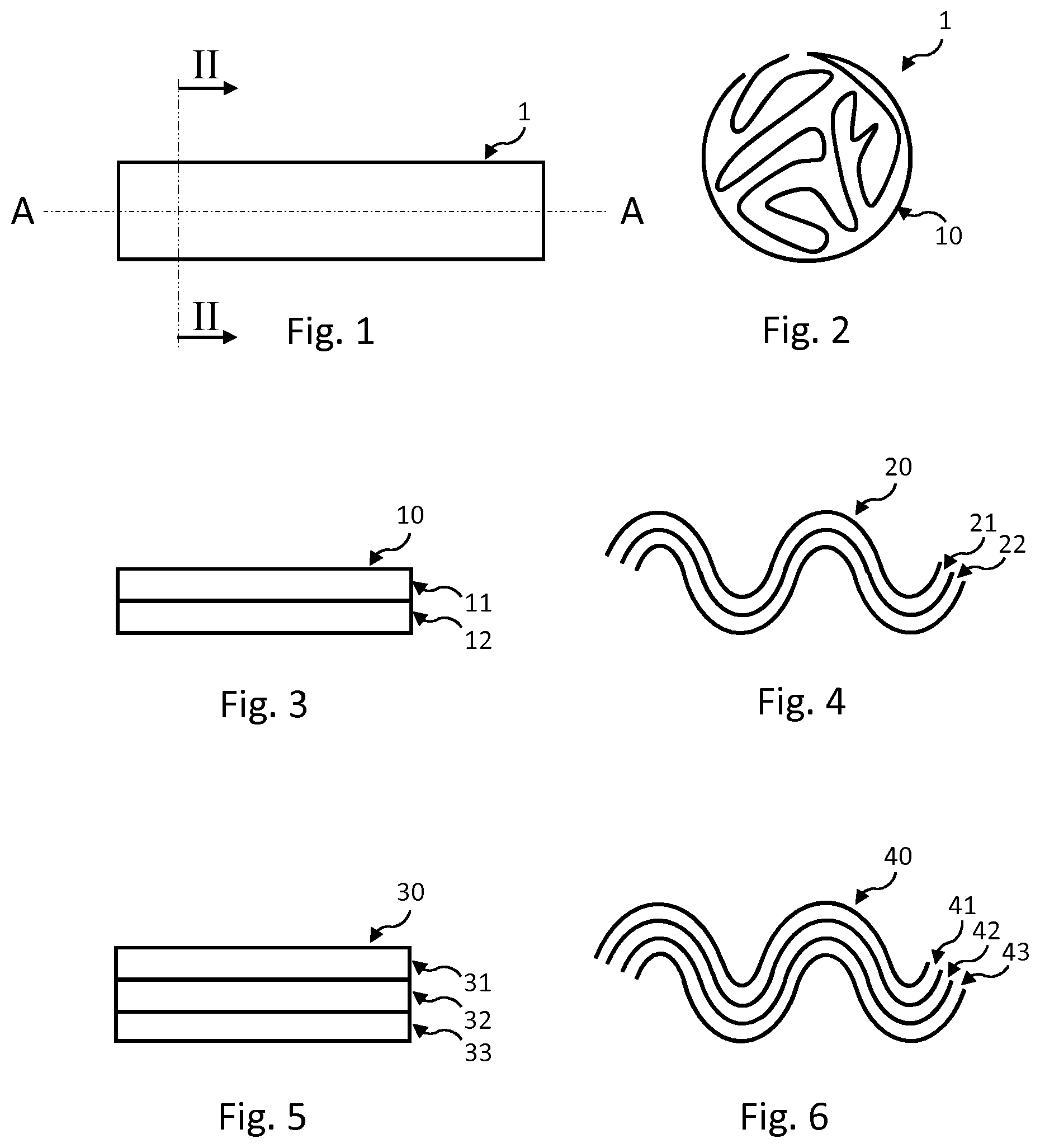
[0053] FIG. 2 shows a schematic cross-sectional view of the aerosolizable structure of FIG. 1.
[0054] FIG. 3 shows a partial schematic cross-sectional view of an example of a layered structure of an aerosolizable structure for use in an article for use with apparatus for heating aerosolizable material to volatilize at least one component of the aerosolizable material.
[0055] FIG. 4 shows a partial schematic cross-sectional view of an example of a layered structure of another aerosolizable structure for use in an article for use with apparatus for heating aerosolizable material to volatilize at least one component of the aerosolizable material.
[0056] FIG. 5 shows a partial schematic cross-sectional view of an example of a layered structure of a further aerosolizable structure for use in an article for use with apparatus for heating aerosolizable material to volatilize at least one component of the aerosolizable material.
[0057] FIG. 6 shows a partial schematic cross-sectional view of an example of a layered structure of a still further aerosolizable structure for use in an article for use with apparatus for heating aerosolizable material to volatilize at least one component of the aerosolizable material.
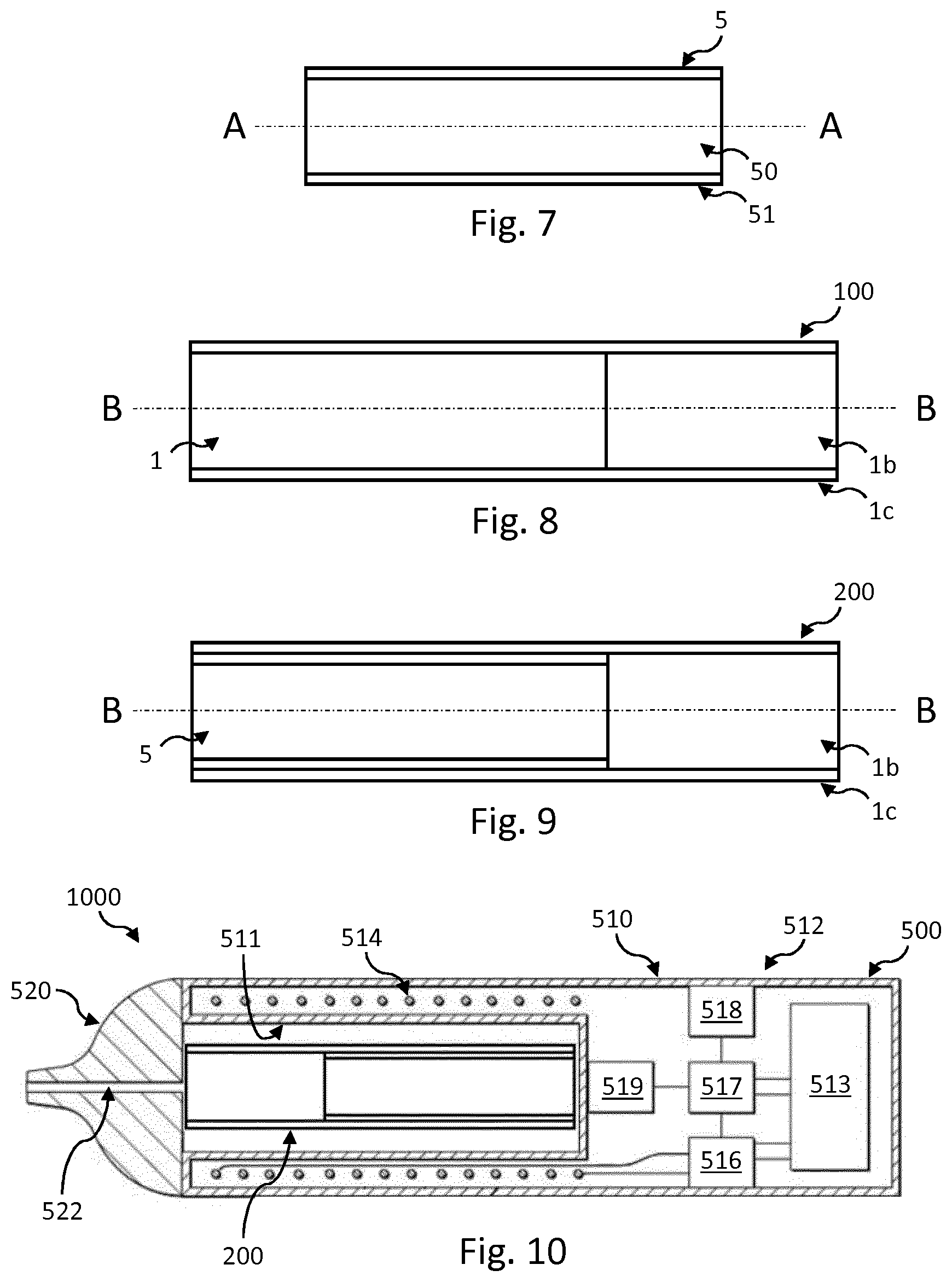
[0058] FIG. 7 shows a schematic cross-sectional side view of an example of another aerosolizable structure for use in an article for use with apparatus for heating aerosolizable material to volatilize at least one component of the aerosolizable material.
[0059] FIG. 8 shows a schematic cross-sectional side view of an example of an article for use with apparatus for heating aerosolizable material to volatilize at least one component of the aerosolizable material.
[0060] FIG. 9 shows a schematic cross-sectional side view of an example of another article for use with apparatus for heating aerosolizable material to volatilize at least one component of the aerosolizable material.
[0061] FIG. 10 shows a schematic cross-sectional side view of an example of a system comprising the article of FIG. 9 and apparatus for heating aerosolizable material of the article to volatilize at least one component of the aerosolizable material.
[0062] FIG. 11 shows a flow diagram showing an example of a method of manufacturing an aerosolizable structure for use in an article for use with apparatus for heating aerosolizable material to volatilize at least one component of the aerosolizable material.
[0063] FIG. 12 shows a flow diagram showing an example of another method of manufacturing an aerosolizable structure for use in an article for use with apparatus for heating aerosolizable material to volatilize at least one component of the aerosolizable material.
[0064] FIG. 13 shows a flow diagram showing an example of a method of manufacturing an article for use with apparatus for heating aerosolizable material to volatilize at least one component of the aerosolizable material.
DETAILED DESCRIPTION
[0065] As used herein, the term "aerosolizable material" includes materials that provide volatilized components upon heating, typically in the form of vapor or an aerosol. "Aerosolizable material" may be a non-tobacco-containing material or a tobacco-containing material. "Aerosolizable material" may, for example, include one or more of tobacco per se, tobacco derivatives, expanded tobacco, reconstituted tobacco, tobacco extract, homogenized tobacco or tobacco substitutes. The aerosolizable material can be in the form of ground tobacco, cut rag tobacco, extruded tobacco, reconstituted tobacco, reconstituted aerosolizable material, liquid, gel, gelled sheet, powder, or agglomerates, or the like. "Aerosolizable material" also may include other, non-tobacco, products, which, depending on the product, may or may not contain nicotine. "Aerosolizable material" may comprise one or more humectants, such as glycerol or propylene glycol.
[0066] As used herein, the term "sheet" denotes an element having a width and length substantially greater than a thickness thereof.
[0067] As used herein, where it is stated that a sheet is "free from aerosolizable material", this means that the sheet itself does not comprise or consist of aerosolizable material, and is not coated or impregnated with aerosolizable material. However, it does not mean that the sheet may not be adjacent (directly or indirectly) to, or adhered to, a sheet that does comprise aerosolizable material.
[0068] As used herein, the term "gathered" includes wrinkled, folded, creased, or otherwise convoluted in shape, whether in a regular or an irregular manner. Correspondingly, as used herein, the term "gathering" includes wrinkling, folding, creasing, or otherwise convoluting in shape, whether in a regular or an irregular manner.
[0069] As used herein, the term "crimped" includes having a plurality of substantially parallel corrugations, or ridges and troughs, therein.
[0070] As used herein, the term "heating material" or "heater material" refers to material that is heatable by penetration with a varying magnetic field.
[0071] Induction heating is a process in which an electrically-conductive object is heated by penetrating the object with a varying magnetic field. The process is described by Faraday's law of induction and Ohm's law. An induction heater may comprise an electromagnet and a device for passing a varying electrical current, such as an alternating current, through the electromagnet. When the electromagnet and the object to be heated are suitably relatively positioned so that the resultant varying magnetic field produced by the electromagnet penetrates the object, one or more eddy currents are generated inside the object. The object has a resistance to the flow of electrical currents. Therefore, when such eddy currents are generated in the object, their flow against the electrical resistance of the object causes the object to be heated. This process is called Joule, ohmic, or resistive heating. An object that is capable of being inductively heated is known as a susceptor.
[0072] It has been found that, when the susceptor is in the form of a closed electrical circuit, magnetic coupling between the susceptor and the electromagnet in use is enhanced, which results in greater or improved Joule heating.
[0073] Magnetic hysteresis heating is a process in which an object made of a magnetic material is heated by penetrating the object with a varying magnetic field. A magnetic material can be considered to comprise many atomic-scale magnets, or magnetic dipoles. When a magnetic field penetrates such material, the magnetic dipoles align with the magnetic field. Therefore, when a varying magnetic field, such as an alternating magnetic field, for example as produced by an electromagnet, penetrates the magnetic material, the orientation of the magnetic dipoles changes with the varying applied magnetic field. Such magnetic dipole reorientation causes heat to be generated in the magnetic material.
[0074] When an object is both electrically-conductive and magnetic, penetrating the object with a varying magnetic field can cause both Joule heating and magnetic hysteresis heating in the object. Moreover, the use of magnetic material can strengthen the magnetic field, which can intensify the Joule and magnetic hysteresis heating.
[0075] In each of the above processes, as heat is generated inside the object itself, rather than by an external heat source by heat conduction, a rapid temperature rise in the object and more uniform heat distribution can be achieved, particularly through selection of suitable object material and geometry, and suitable varying magnetic field magnitude and orientation relative to the object. Moreover, as induction heating and magnetic hysteresis heating do not require a physical connection to be provided between the source of the varying magnetic field and the object, design freedom and control over the heating profile may be greater, and cost may be lower.
[0076] Referring to FIGS. 1 and 2, there are shown schematic side and cross-sectional views of an example of an aerosolizable structure according to an embodiment of the disclosure. The aerosolizable structure 1 is for use in an article for use with apparatus for heating aerosolizable material to volatilize at least one component of the aerosolizable material, such as the article 100 shown in FIG. 8 and described below.
[0077] The aerosolizable structure 1 is substantially cylindrical with a substantially circular cross section (see FIG. 2), but in other embodiments the aerosolizable structure 1 may have an oval or elliptical cross section or be other than cylindrical. In some embodiments, the aerosolizable structure 1 may have a polygonal, quadrilateral, rectangular, square, triangular, star-shaped, or irregular cross section, for example. In this embodiment, the aerosolizable structure 1 is a rod. In some other embodiments, the aerosolizable structure may be tubular with a hollow inner region.
[0078] In this embodiment, the aerosolizable structure 1 is elongate and has a longitudinal axis A-A. A length of the aerosolizable structure 1 in the direction of the longitudinal axis A-A may fall within the range of 40 millimeters to 150 millimeters, such as 70 millimeters to 120 millimeters. In other embodiments, the aerosolizable structure 1 may not be elongate. In some such other embodiments, the aerosolizable structure 1 still has an axial direction A-A that is perpendicular to the cross section of the aerosolizable structure 1 shown in FIG. 2. A width of the aerosolizable structure 1 perpendicular to the axial direction A-A may fall within the range of 4 millimeters to 10 millimeters, such as 5 millimeters to 8 millimeters. A circumference of the aerosolizable structure 1 perpendicular to the axial direction A-A may fall within the range of 12 millimeters to 30 millimeters, such as 16 millimeters to 25 millimeters.
[0079] The aerosolizable structure 1 comprises a layered structure 10. FIG. 3 shows a partial schematic cross-sectional view of the layered structure 10 of the aerosolizable structure 1. The layered structure 10 comprises a first sheet 11 and a second sheet 12. In some embodiments, the layered structure 10 is a laminate. In some embodiments, the first sheet 11 is bonded to the second sheet 12, such as by an adhesive or by a chemical bond. Examples adhesives are polyvinyl acetate (PVA) and ethylene-vinyl acetate (EVA). In other embodiments, the first sheet 11 may be unbonded to the second sheet 12.
[0080] In this embodiment, the first sheet 11 comprises aerosolizable material. The aerosolizable material of the first sheet 11 may be any of the aerosolizable materials discussed herein, such as reconstituted aerosolizable material (e.g. reconstituted tobacco) or in the form of a gel. The first sheet 11 may comprise a substrate, such as a paper, that is impregnated or coated with an aerosolizable material, such as a gel. The aerosolizable material of the first sheet 11 may be cellulosic aerosolizable material.
[0081] In this embodiment, the second sheet 12 comprises heating material that is heatable by penetration with a varying magnetic field. More specifically, the heating material is heatable by penetration with the varying magnetic field to heat the aerosolizable material of the first sheet 11. That is, the heating material is in thermal contact with the aerosolizable material. Since the first and second sheets 11, 12 are part of the same layered structure 10, the heat generated in the second sheet 12 by the penetration with the varying magnetic field is proximate to the first sheet 11 and so relatively efficient heating of the aerosolizable material of the first sheet 11 may be achieved. In some embodiments, the aerosolizable material of the first sheet 11 is in surface contact with the heating material of the second sheet 12. Thus, heat may be conducted directly from the heating material to the aerosolizable material. This can help to further increase the efficiency of heating of the aerosolizable material of the first sheet 11. In other embodiments, the heating material may be kept out of surface contact with the aerosolizable material. For example, in some embodiments, a thermally-conductive barrier that is free from heating material and aerosolizable material may space the heating material from the aerosolizable material. In some embodiments, the thermally-conductive barrier may be a coating on the first sheet 11 or on the second sheet 12. The provision of such a barrier may be advantageous to help to dissipate heat to alleviate hot spots in the heating material.
[0082] In some embodiments in which the aerosolizable material of the first sheet 11 is reconstituted, cellulosic or in gel form, the aerosolizable structure 1 may be free from any aerosolizable material between the reconstituted, cellulosic or gel-form aerosolizable material of the first sheet 11 and the heating material of the second sheet 12. In some embodiments, a benefit of this is that a greater proportion of the heat generated in the second sheet 12 by penetrating the heating material with the varying magnetic field is usable to heat the aerosolizable material of the first sheet 11.
[0083] In this embodiment, the heating material is aluminum , and the second sheet 12 is a sheet of aluminum foil. However, in other embodiments, the heating material may be any one or more of those described herein and/or the sheet 12 comprising heating material may take any of the forms described herein. In this embodiment, the second sheet 12 is free from aerosolizable material. In some embodiments, the second sheet 12 consists of the heating material only. In other embodiments, such as will be described below with reference to FIGS. 5 and 6, this may not be the case. In some embodiments, a benefit of omitting aerosolizable material from the second sheet 12 in this way is that a greater proportion of the heat generated in the second sheet 12 by penetrating the heating material with the varying magnetic field is usable to heat the aerosolizable material of the first sheet 11.
[0084] As is best seen in FIG. 2, the layered structure 10 of the aerosolizable structure 1 is a gathered layered structure 10. In other words, the layered structure 10 has been gathered. Example methods for gathering the layered structure 10 are described in more detail below. This gathering of the layered structure 10 enables a greater proportion of the second sheet 12 comprising heating material to be proximate to the first sheet 11 comprising the aerosolizable material to be heated, as compared to, for example, wrapping the second sheet 12 comprising heating material just around the outside of a plug or gathering of the aerosolizable material or locating a blade or bar of heating material in a relatively concentrated way in a plug or gathering of the aerosolizable material. Accordingly, improved efficiency of heating of the aerosolizable material of the first sheet 11 may be achieved. Moreover, a sheet comprising aerosolizable material can have a relatively high surface area to volume ration, and gathering a sheet comprising aerosolizable material can leave a large proportion of a surface area of the sheet exposed for release of aerosol in use. Furthermore, the gathered sheet can define one or more flow paths along which aerosol generated in use is able to escape from the aerosolizable structure.
[0085] In a variation to the embodiment of FIGS. 1 to 3, the layered structure may be crimped. FIG. 4 shows a partial schematic cross-sectional view of an example of a gathered layered structure of another aerosolizable structure according to an embodiment of the disclosure, in which embodiment the layered structure is crimped. The gathered layered structure 20 of FIG. 4 again comprises a first sheet 21 comprising aerosolizable material, and a second sheet 22 comprising heating material that is heatable by penetration with a varying magnetic field to heat the aerosolizable material of the first sheet 21. Still further, the second sheet 22 is again free from aerosolizable material. In some embodiments, the second sheet 22 consists of the heating material only. In some variations to this embodiment, the first and second sheets 21, 22 may have any of the optional or alternative features described herein in relation to the first and second sheets 11, 12 shown in FIGS. 2 and 3.
[0086] Such crimping can aid gathering of the layered structure 20, and/or dictate how the layered structure 20 becomes gathered, during manufacture of the aerosolizable structure. For example, the distance by which the layered structure 20 is crimped can help to determine the path that the convolutions of the layered structure 20 will take when gathered, and may help to determine a porosity of the resultant gathered layered structure 20. Additionally, or alternatively, such crimping can further increase the proportion of the second sheet 22 that is proximate to the first sheet 21, which in turn helps to increase the efficiency with which the aerosolizable material of the first sheet 21 is heated in use. Some, most or all of the plurality of substantially parallel corrugations, or ridges and troughs, present in the layered structure 20 as a result of the crimping may be parallel to an axial direction A-A of the aerosolizable structure in which the layered structure 20 is comprised.
[0087] In each of the embodiments shown in FIGS. 1 to 3 and FIG. 4 and described herein, the gathered layered structure 10, 20 comprises two sheets 11, 12, 21, 22. However, in some embodiments, the gathered layered structure may comprise more than two sheets. FIG. 5 shows a partial schematic cross-sectional view of an example of a gathered layered structure 30 of a further aerosolizable structure according to an embodiment of the disclosure.
[0088] The gathered layered structure 30 of FIG. 5 has a first sheet 31, a second sheet 32, and a third sheet 33. The second sheet 32 is located between the first sheet 31 and the third sheet 33. Each of the first and second sheets 31, 33 comprises aerosolizable material. The aerosolizable material of the first sheet 31 may be any of the aerosolizable materials discussed herein, such as reconstituted tobacco or in the form of a gel. Similarly, the aerosolizable material of the third sheet 33 may be any of the aerosolizable materials discussed herein, such as reconstituted tobacco or in the form of a gel. One or each of the first and third sheets 31, 33 may be cellulosic aerosolizable material.
[0089] The second sheet 32 comprises heating material that is heatable by penetration with a varying magnetic field to heat the aerosolizable material of the first and third sheets 31, 33. Locating the second sheet 32 between the first and third sheets 31, 33 enables a greater proportion of the total area of the surfaces of the second sheet 32 to be proximate to a sheet 31, 33 comprising aerosolizable material. In turn, this permits heat energy emitted from both surfaces of the second sheet 32 in use to heat aerosolizable material of the layered structure 30.
[0090] In some embodiments, the second sheet 32 is free from aerosolizable material. In some embodiments, the second sheet 32 consists of the heating material only. However, in other embodiments, the second sheet 32 itself may comprise aerosolizable material, such as through the provision of a coating of aerosolizable material, or the impregnation or interweaving of the second sheet 32 with aerosolizable material. In some variations to this embodiment, one or each of the first and third sheets 31, 33 may have any of the optional or alternative features described herein in relation to the first sheet 11 shown in FIGS. 2 and 3. In some variations to this embodiment, the second sheet 32 may have any of the optional or alternative features described herein in relation to the second sheet 12 shown in FIGS. 2 and 3.
[0091] In a variation to the embodiment of FIG. 5, the layered structure may be crimped.
[0092] FIG. 6 shows a partial schematic cross-sectional view of an example of a gathered layered structure of a still further aerosolizable structure according to an embodiment of the disclosure. The gathered layered structure 40 of FIG. 6 is the same as the gathered layered structure 30 of FIG. 5, except that the gathered layered structure 40 of FIG. 6 is crimped. The layered structure 40 of FIG. 6 again comprises first and third sheets 41, 43 comprising aerosolizable material, and again comprises a second sheet 42 therebetween comprising heating material that is heatable by penetration with a varying magnetic field to heat the aerosolizable material of the first and third sheets 41, 43. Any of the herein-described possible variations to the embodiment of FIG. 5 may be made to the embodiment of FIG. 6 to form further embodiments.
[0093] FIG. 7 shows a schematic cross-sectional side view of an example of another aerosolizable structure according to an embodiment of the disclosure. The aerosolizable structure 5 of FIG. 7 is again substantially cylindrical with a substantially circular cross section and a longitudinal axis A-A. A length and/or a width of the aerosolizable structure 5 may, for example, be any one of those discussed herein for the aerosolizable structure 1 of FIGS. 1 to 3. In other embodiments, the aerosolizable structure 5 may have a different cross section, such as any of those discussed herein, or be other than cylindrical, or not be elongate.
[0094] The aerosolizable structure 5 of FIG. 7 comprises a gathered layered structure 50. The gathered layered structure 50 may be the same as any one of the gathered layered structures 10, 20, 30, 40 discussed above, or any of the variants thereof discussed herein.
[0095] The aerosolizable structure 5 also comprises a wrapper 51 that is wrapped around the gathered layered structure 50. The wrapper 51 encircles the gathered layered structure 50, may help to avoid or prevent unravelling or ungathering of the layered structure 50, and helps to protect the gathered layered structure 50 from damage during transport and use. During use, the wrapper 51 may also help to direct the flow of air into and through the gathered layered structure 50, and may help to direct the flow of vapor or aerosol through and out of the gathered layered structure 50.
[0096] In this embodiment, the wrapper 51 is wrapped around the gathered layered structure 50 so that free ends of the wrapper 51 overlap each other. The wrapper 51 may form all of, or a majority of, a circumferential outer surface of the aerosolizable structure 5. The wrapper 51 could be made of any suitable material, such as paper, card, reconstituted aerosolizable material (e.g. reconstituted tobacco), or heating material (e.g. a metal or metal alloy foil, such as aluminum foil). The wrapper 51 may also comprise an adhesive (not shown) that adheres the overlapped free ends of the wrapper 51 to each other. The adhesive may comprise one or more of, for example, gum Arabic, natural or synthetic resins, starches, and varnish. The adhesive helps prevent the overlapped free ends of the wrapper 51 from separating. In other embodiments, the adhesive may be omitted or the wrapper 51 may take a different from to that described. Any one of these types of wrapper may be applied to the other aerosolizable structures described or illustrated herein to form further embodiments.
[0097] Any one of the aerosolizable structures described or illustrated herein may itself be employed as an article for use with apparatus for heating aerosolizable material to volatilize at least one component of the aerosolizable material, such as the apparatus 500 shown in FIG. 10 and described below. However, in other embodiments, the article may comprise an aerosolizable structure along with one or more further components.
[0098] For example, FIG. 8 shows a schematic cross-sectional side view of an example of an article according to an embodiment of the disclosure. The article 100 of FIG. 8 comprises the aerosolizable structure 1 of FIGS. 1 to 3. However, in other embodiments, the aerosolizable structure of the article may be any other one of the aerosolizable structures described herein, for example.
[0099] The article 100 is substantially cylindrical with a substantially circular cross section, but in other embodiments the article 100 may have an oval or elliptical cross section or be other than cylindrical. In some embodiments, the article 100 may have a polygonal, quadrilateral, rectangular, square, triangular, star-shaped, or irregular cross section, for example. In this embodiment, the article 100 is a rod. In some other embodiments, the article may be tubular with a hollow inner region.
[0100] In this embodiment, the article 100 is elongate and has a longitudinal axis B-B. The longitudinal axis B-B of the article 100 is coincident with the longitudinal axis A-A of the aerosolizable structure 1. A length of the article 100 in the direction of the longitudinal axis B-B may fall within the range of 40 millimeters to 150 millimeters, such as 70 millimeters to 120 millimeters. In other embodiments, the article 100 may not be elongate. In some such other embodiments, the article 100 still has an axial direction B-B that is perpendicular to the cross section of the article 100. A width of the article 100 perpendicular to the axial direction B-B may fall within the range of 4 millimeters to 10 millimeters, such as 5 millimeters to 8 millimeters. A circumference of the aerosolizable structure 1 perpendicular to the axial direction B-B may fall within the range of 12 millimeters to 30 millimeters, such as 16 millimeters to 25 millimeters.
[0101] The article 100 of FIG. 8 also comprises a filter 1b. The filter 1b is for filtering aerosol or vapor released from the aerosolizable structure 1 of the article 100 in use. The filter 1b could be of any type used in the tobacco industry. For example, the filter 1b may be made of cellulose acetate. In this embodiment, the filter 1b is substantially cylindrical with a substantially circular cross section and a longitudinal axis. In other embodiments, the filter 1b may have a different cross section, such as any of those discussed herein for aerosolizable structures, or be other than cylindrical, or not be elongate.
[0102] In this embodiment, the filter 1b abuts a longitudinal end of the aerosolizable structure 1 and is axially aligned with the aerosolizable structure 1. In other embodiments, the filter 1b may be spaced from the aerosolizable structure, such as by a gap and/or by one or more further components of the article 100. Example further component(s) are an additive or flavor source (such as an additive- or flavor-containing capsule or thread), which may be held by a body of filtration material or between two bodies of filtration material, for example.
[0103] The article 100 also comprises a wrap 1c that is wrapped around the aerosolizable structure 1 and the filter 1b to retain the filter 1b relative to the aerosolizable structure 1. The wrap 1c encircles the aerosolizable structure 1 and the filter 1b, may help to avoid or prevent unravelling or ungathering of the layered structure of the aerosolizable structure 1, and helps to protect the gathered layered structure from damage during transport and use. During use, the wrap 1c may also help to direct the flow of air into and through the aerosolizable structure 1, and may help to direct the flow of vapor or aerosol through and out of the aerosolizable structure 1.
[0104] In this embodiment, the wrap 1c is wrapped around the aerosolizable structure 1 and the filter 1b so that free ends of the wrap 1c overlap each other. The wrap 1c may form all of, or a majority of, a circumferential outer surface of the article 100. The wrap 1c could be made of any suitable material, such as paper, card, or reconstituted aerosolizable material (e.g. reconstituted tobacco). The wrap 1c may also comprise an adhesive (not shown), such as one of those discussed elsewhere herein, that adheres the overlapped free ends of the wrap 1c to each other. The adhesive helps prevent the overlapped free ends of the wrap 1c from separating. In other embodiments, the adhesive may be omitted or the wrap 1c may take a different from to that described. In other embodiments, the filter 1b may be retained relative to the aerosolizable structure 1 by a connector other than the wrap 1c, such as an adhesive.
[0105] FIG. 9 shows a schematic cross-sectional side view of an example of another article according to an embodiment of the disclosure. The article 200 of FIG. 9 is the same as that of FIG. 8, except that the article 200 has the aerosolizable structure 5 of FIG. 7 in place of the aerosolizable structure 1. Accordingly, the wrap 1c of the article 200 of FIG. 9 is wrapped around the wrapper 51 of the aerosolizable structure 5 and the filter 1b to retain the filter 1b relative to the aerosolizable structure 5. Any of the possible variations to the article 100 of FIG. 8 discussed herein may be made to the article 200 of FIG. 9 to form further embodiments.
[0106] In some embodiments, the article may be provided together with the apparatus for heating the aerosolizable material of the article to volatilize at least one component of the aerosolizable material. The apparatus may comprise a heating zone for receiving the article, and a magnetic field generator for generating a varying magnetic field for penetrating the heating material of the article when the article is located in the heating zone, thereby to heat the aerosolizable material of the article.
[0107] For example, FIG. 10 shows a schematic cross-sectional side view of an example of a system according to an embodiment of the disclosure . The system 1000 comprises the article 200 of FIG. 9 and apparatus 500 for heating aerosolizable material of the article 200 to volatilize at least one component of the aerosolizable material. In other embodiments, the article 200 may be replaced by any of the other articles described herein. In this embodiment, the apparatus 500 is a tobacco heating product (also known in the art as a tobacco heating device or a heat-not-burn device).
[0108] Broadly speaking, the apparatus 500 comprises a heating zone 511 for receiving the article 200, and a magnetic field generator 512 for generating the varying magnetic field for penetrating the heating material of the article 200 when the article 200 is located in the heating zone 511.
[0109] More specifically, the apparatus 500 of this embodiment comprises a body 510 and a mouthpiece 520. The mouthpiece 520 may be made of any suitable material, such as a plastics material, cardboard, cellulose acetate, paper, metal, glass, ceramic, or rubber. The mouthpiece 520 defines a channel 522 therethrough. The mouthpiece 520 is locatable relative to the body 510 so as to cover an opening into the heating zone 511. When the mouthpiece 520 is so located relative to the body 510, the channel 522 of the mouthpiece 520 is in fluid communication with the heating zone 511. In use, the channel 522 acts as a passageway for permitting volatilized material to pass from aerosolizable material of an article inserted in the heating zone 511 to an exterior of the apparatus 500. In this embodiment, the mouthpiece 520 is releasably engageable with the body 510 so as to connect the mouthpiece 520 to the body 510. In other embodiments, the mouthpiece 520 and the body 510 may be permanently connected, such as through a hinge or flexible member. In some embodiments, such as embodiments in which the article itself comprises a mouthpiece, the mouthpiece 520 of the apparatus 500 may be omitted.
[0110] The apparatus 500 may define an air inlet (not shown) that fluidly connects the heating zone 511 with the exterior of the apparatus 500. Such an air inlet may be defined by the body 510 and/or by the mouthpiece 520. A user may be able to inhale the volatilized component(s) of the aerosolizable material by drawing the volatilized component(s) through the channel 522 of the mouthpiece 520. As the volatilized component(s) are removed from the article 200, air may be drawn into the heating zone 511 via the air inlet of the apparatus 500.
[0111] In this embodiment, the body 510 comprises the heating zone 511. In this embodiment, the heating zone 511 comprises a recess 511 for receiving at least a portion of the article 200. In other embodiments, the heating zone 511 may be other than a recess, such as a shelf, a surface, or a projection, and may require mechanical mating with the article in order to co-operate with, or receive, the article. In this embodiment, the heating zone 511 is elongate, and is sized and shaped to accommodate the whole article 200. In other embodiments, the heating zone 511 may be dimensioned to receive only a portion of the article 200.
[0112] In this embodiment, the magnetic field generator 512 comprises an electrical power source 513, a coil 514, a device 516 for passing a varying electrical current, such as an alternating current, through the coil 514, a controller 517, and a user interface 518 for user-operation of the controller 517.
[0113] The electrical power source 513 of this embodiment is a rechargeable battery. In other embodiments, the electrical power source 513 may be other than a rechargeable battery, such as a non-rechargeable battery, a capacitor, a battery-capacitor hybrid, or a connection to a mains electricity supply.
[0114] The coil 514 may take any suitable form. In this embodiment, the coil 514 is a helical coil of electrically-conductive material, such as copper. In some embodiments, the magnetic field generator 512 may comprise a magnetically permeable core around which the coil 514 is wound. Such a magnetically permeable core concentrates the magnetic flux produced by the coil 514 in use and makes a more powerful magnetic field. The magnetically permeable core may be made of iron, for example. In some embodiments, the magnetically permeable core may extend only partially along the length of the coil 514, so as to concentrate the magnetic flux only in certain regions. In some embodiments, the coil may be a flat coil. That is, the coil may be a two-dimensional spiral. In this embodiment, the coil 514 encircles the heating zone 511. The coil 514 extends along a longitudinal axis that is substantially aligned with a longitudinal axis of the heating zone 511. The aligned axes are coincident. In a variation to this embodiment, the aligned axes may be parallel or oblique to each other.
[0115] In this embodiment, the device 516 for passing a varying current through the coil 514 is electrically connected between the electrical power source 513 and the coil 514. In this embodiment, the controller 517 also is electrically connected to the electrical power source 513, and is communicatively connected to the device 516 to control the device 516. More specifically, in this embodiment, the controller 517 is for controlling the device 516, so as to control the supply of electrical power from the electrical power source 513 to the coil 514. In this embodiment, the controller 517 comprises an integrated circuit (IC), such as an IC on a printed circuit board (PCB). In other embodiments, the controller 517 may take a different form. In some embodiments, the apparatus may have a single electrical or electronic component comprising the device 516 and the controller 517. The controller 517 is operated in this embodiment by user-operation of the user interface 518. In this embodiment, the user interface 518 is located at the exterior of the body 510. The user interface 518 may comprise a push-button, a toggle switch, a dial, a touchscreen, or the like. In other embodiments, the user interface 518 may be remote and connected to the rest of the apparatus wirelessly, such as via Bluetooth.
[0116] In this embodiment, operation of the user interface 518 by a user causes the controller 517 to cause the device 516 to cause an alternating electrical current to pass through the coil 514. This causes the coil 514 to generate an alternating magnetic field. The coil 514 and the heating zone 511 of the apparatus 500 are suitably relatively positioned so that, when the article 200 is located in the heating zone 511, the varying magnetic field produced by the coil 514 penetrates the heating material of the article 200. In this embodiment, the heating material is an electrically-conductive material, and so this penetration causes the generation of one or more eddy currents in the heating material. The flow of eddy currents in the heating material against the electrical resistance of the heating material causes the heating material to be heated by Joule heating. When the heating material is made of a magnetic material, the orientation of magnetic dipoles in the heating material changes with the changing applied magnetic field, which causes heat to be generated in the heating material.
[0117] The apparatus 500 of this embodiment comprises a temperature sensor 519 for sensing a temperature of the heating zone 511. The temperature sensor 519 is communicatively connected to the controller 517, so that the controller 517 is able to monitor the temperature of the heating zone 511. On the basis of one or more signals received from the temperature sensor 519, the controller 517 may cause the device 516 to adjust a characteristic of the varying or alternating electrical current passed through the coil 514 as necessary, in order to ensure that the temperature of the heating zone 511 remains within a predetermined temperature range. The characteristic may be, for example, amplitude or frequency or duty cycle. Within the predetermined temperature range, in use the aerosolizable material within an article located in the heating zone 511 is heated sufficiently to volatilise at least one component of the aerosolizable material without combusting the aerosolizable material. Accordingly, the controller 517, and the apparatus 500 as a whole, is arranged to heat the aerosolizable material to volatilize the at least one component of the aerosolizable material without combusting the aerosolizable material. In some embodiments, the temperature range is about 50.degree. C. to about 300.degree. C., such as between about 50.degree. C. and about 250.degree. C., between about 50.degree. C. and about 150.degree. C., between about 50.degree. C. and about 120.degree. C., between about 50.degree. C. and about 100.degree. C., between about 50.degree. C. and about 80.degree. C., or between about 60.degree. C. and about 70.degree. C. In some embodiments, the temperature range is between about 170.degree. C. and about 220.degree. C. In other embodiments, the temperature range may be other than this range. In some embodiments, the upper limit of the temperature range could be greater than 300.degree. C. In some embodiments, the temperature sensor 519 may be omitted. In some embodiments, the heating material may have a Curie point temperature selected on the basis of the maximum temperature to which it is desired to heat the heating material, so that further heating above that temperature by induction heating the heating material is hindered or prevented.
[0118] FIGS. 11 and 12 show flow diagrams showing respective examples of methods of manufacturing an aerosolizable structure.
[0119] The method of FIG. 11 is usable to manufacture any of the aerosolizable structures described herein. The method comprises providing 11a a layered structure, the layered structure having a first sheet 11, 21, 31, 41 comprising aerosolizable material, and a second sheet 12, 22, 32, 42 comprising heating material that is heatable by penetration with a varying magnetic field to heat the aerosolizable material; and gathering 11b the layered structure to form a gathered layered structure 10, 20, 30, 40.
[0120] The second sheet 12, 22, 32, 42 may be free from aerosolizable material. The second sheet 12, 22, 32, 42 may consist of heating material only. In some embodiments, the second sheet comprises aerosolizable material.
[0121] The gathering 11b may comprise feeding the layered structure through a converging funnel. The gathering 11b may cause the layered structure to become substantially cylindrical. The method may comprise crimping the layered structure before the gathering 11b. The providing 11a the layered structure may comprise causing the first sheet 11, 21, 31, 41 to come into contact with the second sheet 12, 22, 32, 42. The method may comprise wrapping a wrapper around the gathered layered structure to form a wrapped gathered layered structure. In some embodiments, the method comprises severing the wrapped gathered layered structure to form a discrete wrapped gathered layered structure.
[0122] The method of FIG. 12 is useable in the manufacture of an aerosolizable structure that has a gathered layered structure comprising three sheets, such as those shown in FIGS. 5 and 6.
[0123] The method comprises providing a layered structure, the layered structure having a first sheet 31, 41 comprising aerosolizable material, a second sheet 32, 42 comprising heating material that is heatable by penetration with a varying magnetic field, and a third sheet comprising aerosolizable material, wherein the second sheet 32, 42 is located between the first and third sheets 31, 33, 41, 43, and wherein the heating material is heatable by penetration with a varying magnetic field to heat the aerosolizable material of the first and third sheets 31, 33, 41, 43.
[0124] In some embodiments, the second sheet 32, 42 is free from aerosolizable material. In some embodiments, the second sheet 32, 42 consists of the heating material only. In some embodiments, the second sheet comprises aerosolizable material.
[0125] In this embodiment, the providing comprises causing 12a the first sheet 31, 41 to come into contact with the second sheet 32, 42. The first and second sheets 31, 41, 32, 42 may be drawn from respective supplies, such as respective bobbins (not shown), before being brought into contact with each other. In other embodiments, the first and second sheets may already be in contact with each other, and so the method does not include this causation. Rather, a combination (such as a laminate) of the first and second sheets 31, 41, 32, 42 may be drawn from a supply, such as a bobbin (not shown).
[0126] In this embodiment, the providing comprises causing 12b the third sheet 33, 43 to come into contact with the second sheet 32, 42. The third sheet 33, 43 may be drawn from a supply, such as a bobbin (not shown), before being brought into contact with the second sheet 32, 42. In other embodiments, the second and third sheets may already be in contact with each other, and so the method does not include this causation. Rather, a combination (such as a laminate) of the second and third sheets 32, 33, 42, 43 may be drawn from a supply, such as a bobbin (not shown). Alternatively, a combination (such as a laminate) of the first, second and third sheets 31, 32, 33, 41, 42, 43 may be drawn from a supply, such as a bobbin (not shown).
[0127] In embodiments in which the aerosolizable structure being manufactured is to have a crimped layered structure, such as that shown in FIG. 6, the method comprises crimping 12c the provided layered structure. The crimping may be performed by transporting the layered structure between a pair of co-operable crimping rollers, which engage and crimp the layered structure as it passes. In other embodiments, in which the aerosolizable structure being manufactured is to have an uncrimped layered structure, such as that shown in FIG. 5, the crimping may be omitted.
[0128] The method comprises gathering 12d the layered structure to form a gathered layered structure 30, 40. In embodiments in which the layered structure is to be crimped, the crimping 12c may occur before the gathering 12d. The gathering 12d may comprise transporting the layered structure 30, 40 through a converging funnel. In other embodiments, the gathering 12d may involve an alternative process, such as squeezing the layered structure 30, 40 between bodies or plates that are movable relative to each other, or such as twisting (e.g. into a helical form). In embodiments in which the layered structure is crimped, the gathering may occur in a direction substantially perpendicular to that of the corrugations, or ridges and troughs, present in the layered structure as a result of the crimping.
[0129] The gathering 12d may cause the layered structure 30, 40 to become substantially cylindrical. This may be caused by the shape of the converging funnel, if used. In other embodiments, the gathering 12d may cause the layered structure 30, 40 to adopt a shape other than cylindrical.
[0130] In this embodiment, the method comprises wrapping 12e a wrapper 51 around the gathered layered structure 30, 40 to form a wrapped gathered layered structure. The wrapper 51 may be drawn from a supply (such as a bobbin) and enveloped around the gathered layered structure 30, 40 by a garniture or endless belt conveyor. The wrapper 51 may comprise adhesive, which may be applied thereto before or during the wrapping 12e, so that when opposite free ends of the wrapper 51 overlap each other the adhesive adheres the opposite free ends to each other. The method may involve passing the wrapped gathered layered structure through or past a dryer to dry the adhesive. As discussed herein, in some embodiments such a wrapper may be omitted. That is, the gathered layered structure may be free from a wrapper. As such, the method of may not include such wrapping 12e.
[0131] In this embodiment, the method comprises severing 12e the wrapped gathered layered structure to form a discrete wrapped gathered layered structure for use in an article, the article being for use with apparatus for heating aerosolizable material to volatilize at least one component of the aerosolizable material. In embodiments in which the wrapping 12e is omitted, the method may comprise severing 12e the gathered layered structure to form a discrete gathered layered structure for use in the article. The severing may comprise cutting, such as by a rotary cutter. In some further other embodiments, the severing 12e may be omitted. For example, in some embodiments, the gathered, or wrapped gathered, layered structure produced so far according to the method may already be dimensioned to suit use in the article without requiring severing.
[0132] FIG. 13 shows a flow diagram showing an example of a method of manufacturing an article for use with apparatus for heating aerosolizable material to volatilize at least one component of the aerosolizable material. The method of FIG. 13 comprises performing 13a the method of FIG. 11 or FIG. 12 (or any of the variants thereof described herein), and connecting 13b a filter to the gathered layered structure using a connector that retains the filter relative to the gathered layered structure. The filter may, for example, be the filter 1b discussed above. The connector may, for example, be any of the connectors discussed herein, such as one of the described wraps 1c.
[0133] In some embodiments, the heating material is aluminum. However, in other embodiments, the heating material may comprise one or more materials selected from the group consisting of: an electrically-conductive material, a magnetic material, and a magnetic electrically-conductive material. In some embodiments, the heating material may comprise a metal or a metal alloy. In some embodiments, the heating material may comprise one or more materials selected from the group consisting of: aluminum, gold, iron, nickel, cobalt, conductive carbon, graphite, steel, plain-carbon steel, mild steel, stainless steel, ferritic stainless steel, copper, and bronze. Other heating material(s) may be used in other embodiments.
[0134] In some embodiments, the sheet comprising heating material is a free from holes or discontinuities. In some embodiments, the sheet comprising heating material comprises a foil, such as a metal or metal alloy foil, e.g. aluminum foil. However, in some embodiments, the sheet comprising heating material may have holes or discontinuities. For example, in some embodiments, the sheet comprising heating material may comprise a mesh, a perforated sheet, or a perforated foil, such as a metal or metal alloy perforated foil, e.g. perforated aluminum foil.
[0135] In some embodiments, such as those in which the heating material comprises iron, such as steel (e.g. mild steel or stainless steel) or aluminum, the sheet comprising heating material may be coated to help avoid corrosion or oxidation of the heating material in use. Such coating may, for example, comprise nickel plating, gold plating, or a coating of a ceramic or an inert polymer. In some embodiments, the sheet comprising heating material comprises or consists of nickel plated aluminum foil.
[0136] The heating material may have a skin depth, which is an exterior zone within which most of an induced electrical current and/or induced reorientation of magnetic dipoles occurs. By providing that the heating material has a relatively small thickness, a greater proportion of the heating material may be heatable by a given varying magnetic field, as compared to heating material having a depth or thickness that is relatively large as compared to the other dimensions of the heating material. Thus, a more efficient use of material is achieved and, in turn, costs are reduced.
[0137] In some embodiments, the aerosolizable material comprises tobacco. However, in other embodiments, the aerosolizable material may consist of tobacco, may consist substantially entirely of tobacco, may comprise tobacco and aerosolizable material other than tobacco, may comprise aerosolizable material other than tobacco, or may be free from tobacco. In some embodiments, the aerosolizable material may comprise a vapor or aerosol forming agent or a humectant, such as glycerol, propylene glycol, triacetin, or diethylene glycol. In some embodiments, the aerosolizable material is non-liquid aerosolizable material, and the apparatus is for heating non-liquid aerosolizable material to volatilize at least one component of the aerosolizable material.
[0138] In some embodiments, the article 100, 200 is a consumable article. Once all, or substantially all, of the volatilizable component(s) of the aerosolizable material in the article 100, 200 has/have been spent, the user may remove the article 100, 200 from the heating zone 511 of the apparatus 500 and dispose of the article 100, 200. The user may subsequently re-use the apparatus 500 with another of the articles 100, 200. However, in other respective embodiments, the article may be non-consumable, and the apparatus and the article may be disposed of together once the volatilizable component(s) of the aerosolizable material has/have been spent.
[0139] In some embodiments, the article 100, 200 is sold, supplied or otherwise provided separately from the apparatus 500 with which the article 100, 200 is usable. However, in some embodiments, the apparatus 500 and one or more of the articles 100, 200 may be provided together as a system, such as a kit or an assembly, possibly with additional components, such as cleaning utensils.
[0140] In order to address various issues and advance the art, the entirety of this disclosure shows by way of illustration and example various embodiments in which the claimed invention may be practiced and which provide for superior aerosolizable structures for use in articles for use with apparatus for heating aerosolizable material, articles for use with apparatus for heating aerosolizable material to volatilize at least one component of the aerosolizable material, methods of manufacturing an aerosolizable structure for use in an article for use with apparatus for heating aerosolizable material to volatilize at least one component of the aerosolizable material, methods of manufacturing an article for use with apparatus for heating aerosolizable material to volatilize at least one component of the aerosolizable material, and systems comprising such an article and such apparatus. The advantages and features of the disclosure are of a representative sample of embodiments only, and are not exhaustive and/or exclusive. They are presented only to assist in understanding and teach the claimed and otherwise disclosed features. It is to be understood that advantages, embodiments, examples, functions, features, structures and/or other aspects of the disclosure are not to be considered limitations on the disclosure as defined by the claims or limitations on equivalents to the claims, and that other embodiments may be utilized and modifications may be made without departing from the scope and/or spirit of the disclosure. Various embodiments may suitably comprise, consist of, or consist in essence of, various combinations of the disclosed elements, components, features, parts, steps, means, etc. The disclosure may include other inventions not presently claimed, but which may be claimed in future.
* * * * *
D00000
D00001
D00002
D00003
XML
uspto.report is an independent third-party trademark research tool that is not affiliated, endorsed, or sponsored by the United States Patent and Trademark Office (USPTO) or any other governmental organization. The information provided by uspto.report is based on publicly available data at the time of writing and is intended for informational purposes only.
While we strive to provide accurate and up-to-date information, we do not guarantee the accuracy, completeness, reliability, or suitability of the information displayed on this site. The use of this site is at your own risk. Any reliance you place on such information is therefore strictly at your own risk.
All official trademark data, including owner information, should be verified by visiting the official USPTO website at www.uspto.gov. This site is not intended to replace professional legal advice and should not be used as a substitute for consulting with a legal professional who is knowledgeable about trademark law.