Sub-unit Of A Smoking Article And Method For Making It
EUSEPI; Ivan ; et al.
U.S. patent application number 16/956418 was filed with the patent office on 2021-04-08 for sub-unit of a smoking article and method for making it. The applicant listed for this patent is G.D S.P.A.. Invention is credited to Nicola BALDANZA, Gabriele BENNI, Marco ESPOSTI, Ivan EUSEPI, Luca FEDERICI, Giuliano GAMBERINI, Massimo SARTONI, Eros STIVANI.
| Application Number | 20210100279 16/956418 |
| Document ID | / |
| Family ID | 1000005307121 |
| Filed Date | 2021-04-08 |


| United States Patent Application | 20210100279 |
| Kind Code | A1 |
| EUSEPI; Ivan ; et al. | April 8, 2021 |
SUB-UNIT OF A SMOKING ARTICLE AND METHOD FOR MAKING IT
Abstract
A sub-unit of a smoking article includes a tubular wrapper which extends along a main axis of extension and internally defines a containment chamber containing a filling material of the tobacco industry. The tubular wrapper has an access opening on at least one of its ends for access to the containment chamber. The sub-unit also includes at least one closing element applied to the at least one end of the tubular wrapper to define a closing wall for closing the access opening. The closing element extends transversely to the main axis of extension in such a way as to at least partly close the access opening.
| Inventors: | EUSEPI; Ivan; (Castelmaggiore (Bologna), IT) ; ESPOSTI; Marco; (Casalecchio di Reno (Bologna), IT) ; BENNI; Gabriele; (Sasso Marconi (Bologna), IT) ; BALDANZA; Nicola; (Zola Predosa (Bologna), IT) ; STIVANI; Eros; (Bologna, IT) ; GAMBERINI; Giuliano; (Crevalcore (Bologna), IT) ; SARTONI; Massimo; (Bologna, IT) ; FEDERICI; Luca; (Bologna, IT) | ||||||||||
| Applicant: |
|
||||||||||
|---|---|---|---|---|---|---|---|---|---|---|---|
| Family ID: | 1000005307121 | ||||||||||
| Appl. No.: | 16/956418 | ||||||||||
| Filed: | December 19, 2018 | ||||||||||
| PCT Filed: | December 19, 2018 | ||||||||||
| PCT NO: | PCT/IB2018/060313 | ||||||||||
| 371 Date: | June 19, 2020 |
| Current U.S. Class: | 1/1 |
| Current CPC Class: | A24D 1/20 20200101; A24D 1/027 20130101; A24C 5/54 20130101 |
| International Class: | A24D 1/02 20060101 A24D001/02; A24C 5/54 20060101 A24C005/54; A24D 1/20 20060101 A24D001/20 |
Foreign Application Data
| Date | Code | Application Number |
|---|---|---|
| Dec 22, 2017 | IT | 102017000149237 |
| Feb 2, 2018 | IT | 102018000002358 |
Claims
1. A sub-unit of a smoking article comprising a tubular wrapper extending along a main axis of extensions and internally defining a containment chamber containing a filling material of the tobacco industry, the tubular wrapper having an access opening on at least one of its ends for access to the containment chamber; wherein it comprises at least one closing element applied to the at least one end of the tubular wrapper to define a closing wall to close the access opening, the closing element extending transversely to the main axis of extension so as to at least partly close the access opening.
2. The sub-unit according to claim 1, wherein the closing element has a substantially circular profile.
3. The sub-unit according to claim 1, wherein the closing element has a substantially square profile.
4. The sub-unit according to claim 1, wherein each closing element is made of flame retardant material.
5. The sub-unit according to claim 4, wherein the flame retardant material is a metallic material.
6. The sub-unit according to claim 1, wherein the at least one closing element is located inside the tubular wrapper and is coupled to an inside surface of the respective end portion of the tubular wrapper.
7. The sub-unit according to claim 6, wherein the at least one closing element is shaped or deformed in such a way as to define a convex surface directed towards the containment chamber.
8. The sub-unit according to claim 6, wherein the closing element has at least one edge portion and the closing element is coupled to the tubular wrapper by interference of the edge portion with an inside wall of the end.
9. The sub-unit according to claim 6, wherein the closing element has at least one edge portion and the closing element is coupled to the tubular wrapper by gluing of the edge portion to an inside wall of the end.
10. The sub-unit according to claim 1, wherein the at least one closing element is applied on the outside of the tubular wrapper and is coupled to an outside surface of the respective end of the tubular wrapper.
11. The sub-unit according to claim 10, wherein the closing element has at least one edge portion and the closing element is coupled to the tubular wrapper by gluing of the edge portion to an outside wall of the end.
12. The sub-unit according to claim 1, wherein the closing element has a surface extension such as to entirely cover the access opening and is provided with at least one hole or perforation for increasing the permeability of the closing element to air or gases.
13. The sub-unit according to wherein the closing element has a surface extension such as to partly cover the access opening in such a way as to define uncovered portions of the access opening intended to allow air or gas to pass through.
14. The sub-unit according to claim 1, wherein the closing element comprises a piece of sheet material having at least one edge portion which is suitably deformed to adapt to the shape of the end.
15. The sub-unit according to claim 1, wherein the closing element comprises a porous body.
16. The sub-unit according to claim 1, comprising a rod-shaped segment of the tobacco industry, having one end coupled and connected to a first end of the tubular wrapper defining a closing wall, transverse to the wrapping axis, at least partly closing the containment chamber, wherein the closing element is applied to a second end, opposite to the first end, of the tubular wrapper.
17. (canceled)
18. The sub-unit according to claim 16, wherein the tubular wrapper is made of rigid material and the rod-shaped segment has one end abutted against, and coupled to, a first end of the tubular wrapper defining a closing wall, transverse to the wrapping axis, at least partly closing the containment chamber, wherein the closing element is applied to a second end, opposite to the first end, of the tubular wrapper.
19. (canceled)
20. The sub-unit according to claim 1, wherein the tubular wrapper has a configuration which, at its first end, is closed by a closing base, transverse to the main axis of extension, to at least partly close the containment chamber, and wherein the closing element is applied to a second end, opposite to the first end, of the tubular wrapper.
21. The sub-unit according to claim 20, wherein the closing base is made as one with the tubular wrapper.
22. The sub-unit according to claim 1, wherein the tubular wrapper has two access openings, opposite to each other, on opposite ends of the tubular wrapper, for access to the containment chamber, and wherein the sub-unit comprises two closing elements, each coupled to a respective end of the tubular wrapper to at least partly close the respective access opening.
Description
TECHNICAL FIELD
[0001] This invention relates to a sub-unit of a smoking article and to the related method for making it.
[0002] In particular, this invention is intended for making a sub-unit of a smoking article of the Heat Not Burn (HNB) type or of an electronic cigarette or of a conventional cigarette.
BACKGROUND ART
[0003] That type of article may be inhaled by heating but not burning the active portion.
[0004] The active portion may in fact be a piece comprising an aerosol-generating element, or a heat-not-burn type tobacco containing product.
[0005] In this case the tobacco may be for example of the type which is pre-treated, reconstituted, homogenized, or cast leaf, which in particular takes the form of loose material such as pellets or in the form of a crimp cut ribbon.
[0006] However, in this context, in order to be able to ensure the quality of the finished product, it is important to guarantee the correct containment and retaining of the filling material, which is the active portion, both during the entire production process and after it has been completed.
[0007] Prior art production methods involve making a smoking article formed by a rod-shaped body (for example a filter or a heating element) and a tube made of wrapping material which is then filled with the aerosol-generating element.
[0008] However, that solution is not very suitable for guaranteeing the integrity of the article in particular because it does not allow correct retaining of the active portion in the tubular body to be ensured.
DISCLOSURE OF THE INVENTION
[0009] In this context, the technical purpose which forms the basis of this invention is to propose a method for making a sub-unit of a smoking article which overcomes at least some of the above-mentioned disadvantages of the prior art.
[0010] In particular, the aim of this invention is to provide a method for making a sub-unit of a smoking article which allows the structural integrity of the smoking article to be guaranteed, in particular preventing the unwanted escape of the type of active portion used to make its filling.
[0011] In this context, the technical purpose which forms the basis of this invention is to propose a sub-unit of a smoking article and the related method for making it which overcome at least some of the above-mentioned disadvantages of the prior art.
[0012] In particular, the aim of this invention is to provide a sub-unit of a smoking article and the method for making it which are able to guarantee the correct and efficient containment of the filling material content.
[0013] The technical purpose indicated and the aims specified are substantially achieved by a sub-unit of a smoking article and method for making it, comprising the technical features described in one or more of the accompanying claims.
[0014] This invention shows a sub-unit of a smoking article, for example but not limited to a smoking article of the HNB type, which comprises at least one tubular wrapper (or wrapping) which extends along a main axis of extension and internally defines a containment chamber containing a filling material of the tobacco industry.
[0015] Preferably, the tubular wrapper has a cylindrical section.
[0016] That sub-unit comprises, at least at one end of the at least one tubular wrapper, a closing wall, transverse to the main axis of extension, which at least partly closes the containment chamber.
[0017] In particular, one possible aspect shows a sub-unit of a smoking article which comprises at least one tubular wrapper which extends along a main axis of extension and internally defines a containment chamber containing a filling material of the tobacco industry.
[0018] The sub-unit comprises, at least at one end of the at least one tubular wrapper, a closing wall, transverse to the main axis of extension, which at least partly closes the containment chamber.
[0019] The closing wall is defined by folding an end portion of the respective end of the at least one tubular wrapper.
[0020] Advantageously, the at least one tubular wrapper is made of material which is at least partly metallic or metallized, that is to say, comprising metallic particles intended to render the at least one tubular wrapper unsuitable for combustion.
[0021] Preferably, the sub-unit comprises a strip and the at least one tubular wrapper is defined by the strip wrapped round the main axis of extension of the tubular wrapper.
[0022] Alternatively, the sub-unit comprises a rigid tubular body of the tobacco industry and the at least one tubular wrapper is defined by the tubular body. The term "rigid tubular body" refers to a tubular body having greater rigidity than the strip (the latter being made, for example, of a sheet of paper), in particular for constituting a supporting portion of the sub-unit. In more detail, the term "rigid" implies that it is made of a sufficiently rigid material (cardboard or paperboard) or with a thickness such that it is usually able to withstand bending or compression stresses but, within the scope of this invention, that feature does not prejudice the possibility that some rigid parts of the tubular body may be suitably permanently folded and/or deformed.
[0023] Alternatively, the sub-unit comprises the rigid tubular body and the strip, where the strip is wrapped round the tubular body.
[0024] Therefore, the tubular body defines a first tubular wrapper and the strip in turn defines a second tubular wrapper.
[0025] Preferably, the closing wall is defined by folding an end portion of a respective end of the strip.
[0026] Alternatively, the closing wall is defined by folding an end portion of a respective end of the tubular body.
[0027] Alternatively, the closing wall is defined by folding an end portion of a respective end of the strip and of the tubular body.
[0028] Preferably, the end portion of the strip and/or of the tubular body forming the closing wall is made of thermally conductive material or in any case has greater thermal conductivity than the remaining portion of the strip and/or of the tubular body.
[0029] Advantageously, at least one end portion of a respective end of the at least one tubular wrapper defines a closing circle having a plurality of fold points and at least one closing wall is defined by mechanically deforming the closing circle along that plurality of fold points.
[0030] The plurality of fold points may comprise four fold points angularly spaced around the main axis of extension and comprising a first pair of fold points which are opposite each other relative to the main axis of extension and a second pair of fold points which are opposite each other relative to the main axis of extension.
[0031] Preferably, the mechanical deformation causes the first pair of points to be superposed on the second pair of points.
[0032] Alternatively, the plurality of fold points comprises four fold points angularly spaced around the main axis of extension and the mechanical deformation causes the four fold points to come into abutment with each other inside the containment chamber.
[0033] Alternatively, the mechanical deformation causes torsional folding of the plurality of fold points around the main axis of extension.
[0034] The sub-unit may comprise a rod-shaped segment of the tobacco industry which has one end coupled and connected to a first end of the at least one tubular wrapper defining a closing wall, transverse to the wrapping axis, at least partly closing the containment chamber.
[0035] Preferably, the at least one tubular wrapper has at its second end, opposite to the first end, a closing wall defined by the folding of an end portion of the second end.
[0036] Preferably, the rod-shaped segment is connected to the at least one tubular wrapper by a connecting strip of wrapping material.
[0037] Advantageously, that connecting strip may coincide with the strip defining the tubular wrapper.
[0038] Preferably, the rod-shaped segment is at least partly inserted in the containment chamber in such a way that the at least one tubular wrapper fits round the outside of an end portion of the rod-shaped segment.
[0039] Alternatively, the at least one tubular wrapper has a configuration which, at its first end, is closed by a closing base, transverse to the main axis of extension, to at least partly close the containment chamber.
[0040] Preferably, the at least one tubular wrapper has at its second end, opposite to the first end, a closing wall defined by the folding of an end portion of the second end.
[0041] Preferably, the closing base is made as one with the at least one tubular wrapper.
[0042] Alternatively, the sub-unit comprises, at each end of the at least one tubular wrapper, a closing wall, transverse to the wrapping axis, for at least partly closing the containment chamber, defined by folding an end portion of a respective end of the at least one tubular wrapper.
[0043] Preferably, each closing wall is made of flame retardant material.
[0044] Preferably, each closing wall is made of porous material or has a plurality of holes or perforations for increasing the air or gas permeability of the closing wall.
[0045] According to this invention, a sub-unit of a smoking article is shown which comprises a tubular wrapper extending along a main axis of extension.
[0046] That tubular wrapper internally defines a containment chamber containing a filling material of the tobacco industry and has an access opening on at least one of its ends for access to the containment chamber.
[0047] The sub-unit also comprises at least one closing element applied to the at least one end of the tubular wrapper to define its closing wall.
[0048] The closing element extends transversely to the main axis of extension in such a way as to at least partly close the access opening.
[0049] Preferably, the closing element has a substantially circular profile.
[0050] Alternatively, the closing element has a substantially square profile.
[0051] Preferably, each closing element is made of a material with high thermal conductivity.
[0052] Still more preferably, each closing element is made of flame retardant material.
[0053] In one embodiment, each closing element is at least partly made of metallic or metallized material, that is to say, comprising metallic particles intended to render each closing element unsuitable for combustion.
[0054] In particular, the at least one closing element is located inside the tubular wrapper and is coupled to an inside surface of the respective end portion of the tubular wrapper.
[0055] Preferably, the at least one closing element is deformed in such a way as to define a convex surface directed towards the containment chamber.
[0056] That convex surface is suitable for causing the filling material to be moved away from a respective access opening of the tubular wrapper.
[0057] Still more preferably, the closing element comprises at least one edge portion and the closing element is coupled to the tubular wrapper by interference of the edge portion with an inside wall of the end of the tubular wrapper.
[0058] Alternatively, the closing element comprises at least one edge portion and the closing element is coupled to the tubular wrapper by gluing the edge portion to an inside wall of the end of the tubular wrapper.
[0059] According to a different embodiment of the same aspect of this invention, the at least one closing element is applied on the outside of the tubular wrapper and is coupled to an outside surface of the respective end of the tubular wrapper.
[0060] Preferably, the closing element comprises at least one edge portion and the closing element is coupled to the tubular wrapper by gluing the edge portion to an outside wall of the end of the tubular wrapper.
[0061] In general, the closing element has a surface extension such as to entirely cover the access opening and is provided with at least one hole or perforation for increasing its air or gas permeability.
[0062] That hole may even be configured to facilitate a movement, management or application of the closing element relating to the tubular wrapper.
[0063] Alternatively, the closing element has a surface extension such as to partly cover the access opening in such a way as to define uncovered portions of the access opening intended to allow air or gas to pass through.
[0064] Preferably, the closing element comprises a piece of sheet material having at least one edge portion which is suitably deformed to adapt to the shape of the respective end of the tubular wrapper.
[0065] Alternatively, the closing element comprises a porous body.
[0066] According to one particular embodiment, again relevant to this second aspect, the sub-unit comprises a rod-shaped segment of the tobacco industry which has one end coupled and connected to a first end of the tubular wrapper defining a closing wall, transverse to the wrapping axis, at least partly closing the containment chamber.
[0067] In that configuration, the closing element is applied to a second end, opposite to the first end, of the tubular wrapper.
[0068] Preferably, the rod-shaped segment is connected to the tubular wrapper by a connecting strip of wrapping material.
[0069] Still more preferably, that connecting strip may coincide with the strip defining the tubular wrapper.
[0070] Preferably, the tubular wrapper is made of rigid material and the rod-shaped segment has one end abutted against, and coupled to, a first end of the tubular wrapper defining a closing wall, transverse to the wrapping axis, at least partly closing the containment chamber.
[0071] Again in that configuration, the closing element is applied to a second end, opposite to the first end, of the tubular wrapper.
[0072] Preferably, the rod-shaped segment is at least partly inserted in the containment chamber in such a way that the tubular wrapper fits round the outside of an end portion of the rod-shaped segment.
[0073] Alternatively, the tubular wrapper has a configuration which, at its first end, is closed by a closing base, transverse to the main axis of extension, to at least partly close the containment chamber, and wherein the tubular wrapper has at its second end, opposite to the first end, a closing wall defined by the folding of an end portion of the second end.
[0074] Preferably, that closing base is made as one with the tubular wrapper.
[0075] Alternatively, the tubular wrapper has two access openings, opposite to each other, on opposite end portions of the tubular wrapper for access to the containment chamber, and the sub-unit comprises two closing elements, each coupled to a respective end portion of the tubular wrapper to at least partly close the respective access opening.
[0076] According to further aspect, a sub-unit of a smoking article is shown which comprises a tubular wrapper extending along a main axis of extension.
[0077] The tubular wrapper internally defines a containment chamber which contains a filling material of the tobacco industry.
[0078] The tubular wrapper also has an access opening on at least one of its end portions for access to the containment chamber.
[0079] The sub-unit also comprises at least one closing element applied to the at least one end portion of the tubular wrapper to define a closing wall for closing the access opening.
[0080] That closing element extends transversely to the main axis of extension in such a way as to at least partly close the access opening.
[0081] Moreover, the end portion has at least one blocking portion, transverse to the main axis of extension, extending from a wall of the tubular wrapper towards the main axis of extension to define a blocking surface for blocking the closing element.
[0082] Preferably, the at least one blocking portion is defined by a permanent deformation of the respective end in which the blocking portion is present.
[0083] Preferably, the at least one blocking portion comprises an annular ridge of an inside surface of the respective end.
[0084] Preferably, the end has a pair of blocking portions and the closing element is interposed between the blocking portions and blocked between them in a configuration of at least partial closure of the access opening.
[0085] In particular, at least one blocking portion of the pair of blocking portions, preferably the inner one, is defined by an annular ridge.
[0086] Preferably, both of the blocking portions of the pair of blocking portions are defined by an annular ridge.
[0087] Alternatively, one blocking portion of the pair of blocking portions, preferably the inner one, is defined by an annular ridge and the other blocking portion is defined by an edge bead on an end portion of the end.
[0088] Therefore, preferably, the end portion has a pair of blocking portions, both transverse to the main axis of extension, which extend from a wall of the tubular wrapper towards the axis of extension of the tubular wrapper, and the closing element is interposed between the pair of blocking surfaces, to define a closing wall for closing the access opening.
[0089] Again in this context, the closing element extends transversely to the main axis of extension in such a way as to at least partly close the access opening.
[0090] In more detail, the pair of blocking portions has a first blocking portion, preferably defined by a narrowing of the tubular wrapper, interposed between the filling material and the closing element, and a second blocking portion, preferably defined by an edge bead on the end portion of the tubular wrapper, interposed between the closing element and an environment outside the tubular wrapper.
[0091] Preferably, the closing element has a substantially circular profile.
[0092] Alternatively, the closing element has a substantially square profile.
[0093] Preferably, each closing element is made of a material with high thermal conductivity.
[0094] Still more preferably, each closing element is made of flame retardant material.
[0095] In one embodiment, each closing element is at least partly made of metallic or metallized material, that is to say, comprising metallic particles intended to render each closing element unsuitable for combustion.
[0096] In particular, the at least one closing element is located inside the tubular wrapper and is coupled to an inside surface of the respective end portion of the tubular wrapper.
[0097] Preferably, the at least one closing element is deformed in such a way as to define a convex surface directed towards the containment chamber.
[0098] That convex surface is suitable for causing the filling material to be moved away from a respective access opening of the tubular wrapper.
[0099] Still more preferably, the closing element comprises at least one edge portion and the closing element is coupled to the tubular wrapper by interference of the edge portion with an inside wall of the end of the tubular wrapper.
[0100] Alternatively, the closing element comprises at least one edge portion and the closing element is coupled to the tubular wrapper by gluing the edge portion to an inside wall of the end of the tubular wrapper.
[0101] In general, the closing element has a surface extension such as to entirely cover the access opening and is provided with at least one hole or perforation for increasing its air or gas permeability.
[0102] That hole may even be configured to facilitate a movement, management or application of the closing element relating to the tubular wrapper.
[0103] Alternatively, the closing element has a surface extension such as to partly cover the access opening in such a way as to define uncovered portions of the access opening intended to allow air or gas to pass through.
[0104] Preferably, the closing element comprises a piece of sheet material having at least one edge portion which is suitably deformed to adapt to the shape of the respective end of the tubular wrapper.
[0105] Alternatively, the closing element comprises a porous body.
[0106] According to one particular embodiment, again relevant to this third aspect, the sub-unit comprises a rod-shaped segment of the tobacco industry which has one end coupled and connected to a first end of the tubular wrapper defining a closing wall, transverse to the wrapping axis, at least partly closing the containment chamber.
[0107] In that configuration, the closing element is applied to a second end, opposite to the first end, of the tubular wrapper.
[0108] Moreover, the second end to which the closing element is applied, has at least one respective blocking portion, transverse to the main axis of extension, extending from a wall of the tubular wrapper towards the main axis of extension to define a blocking surface for blocking the respective closing element.
[0109] Preferably, the rod-shaped segment is connected to the tubular wrapper by a connecting strip of wrapping material.
[0110] Still more preferably, that connecting strip may coincide with the strip defining the tubular wrapper.
[0111] Preferably, the tubular wrapper is made of rigid material and the rod-shaped segment has one end abutted against, and coupled to, a first end of the tubular wrapper defining a closing wall, transverse to the wrapping axis, at least partly closing the containment chamber.
[0112] Again in that configuration, the closing element is applied to a second end, opposite to the first end, of the tubular wrapper.
[0113] Preferably, the rod-shaped segment is at least partly inserted in the containment chamber in such a way that the tubular wrapper fits round the outside of an end portion of the rod-shaped segment.
[0114] Alternatively, the tubular wrapper has a configuration which, at its first end, is closed by a closing base, transverse to the main axis of extension, to at least partly close the containment chamber, and wherein the closing element is applied to a second end, opposite to the first end, of the tubular wrapper.
[0115] Moreover, the second end to which the closing element is applied, has at least one respective blocking portion, transverse to the main axis of extension, extending from a wall of the tubular wrapper towards the main axis of extension to define a blocking surface for blocking the respective closing element.
[0116] Preferably, that closing base is made as one with the tubular wrapper.
[0117] Alternatively, the tubular wrapper has two access openings, opposite to each other, on opposite end portions of the tubular wrapper for access to the containment chamber, and the sub-unit comprises two closing elements, each coupled to a respective end portion of the tubular wrapper to at least partly close the respective access opening.
[0118] Moreover, both of the ends to which the closing elements are applied have at least one respective blocking portion, transverse to the main axis of extension, extending from a wall of the tubular wrapper towards the main axis of extension to define a blocking surface for blocking the respective closing element.
[0119] According to this invention, the containment chamber may be closed using different types of closing walls.
[0120] In other words, it is possible to make one closing wall according to one of the three aspects of this invention indicated above and to make another closing wall of the same tubular wrapper according to a different aspect of this invention.
[0121] Such combinations therefore allow, for example, one wall to be made by folding a respective end of the at least one tubular wrapper and the other wall to be made by applying a closing element combined with the presence or absence of blocking surfaces.
[0122] Advantageously, the aspects for making this invention which are indicated above and described make available sub-units of smoking articles which are able to guarantee optimum containment of the filling material in the sub-unit itself, thereby allowing elimination of the risk of having in the production chain non-conforming articles whose filling is insufficient and which are therefore not fit for marketing.
[0123] A method for making a sub-unit of a smoking article, for example an HNB-type smoking article, is also described.
[0124] According to a first aspect, the method comprises the steps of: [0125] preparing at least one tubular wrapper of the tobacco industry, extending along a main axis of extension and internally having a containment chamber; [0126] inserting a filling material of the tobacco industry into the containment chamber; [0127] making at least at one end of the tubular wrapper, a closing wall, transverse to the main axis of extension, for at least partly closing the at least one end of the tubular wrapper.
[0128] The step of making a closing wall is performed by folding an end portion of a respective end of the at least one tubular wrapper.
[0129] Preferably, the step of preparing a tubular wrapper is accomplished by preparing a tubular body of the tobacco industry.
[0130] Alternatively, the step of preparing a tubular wrapper comprises the steps of preparing a strip and wrapping that strip round the main axis of extension.
[0131] Alternatively, the step of preparing a tubular wrapper comprises the steps of preparing a tubular body of the tobacco industry and a strip and then wrapping the strip round the tubular body.
[0132] In particular, the tubular body defines a first tubular wrapper and the strip defines a second tubular wrapper.
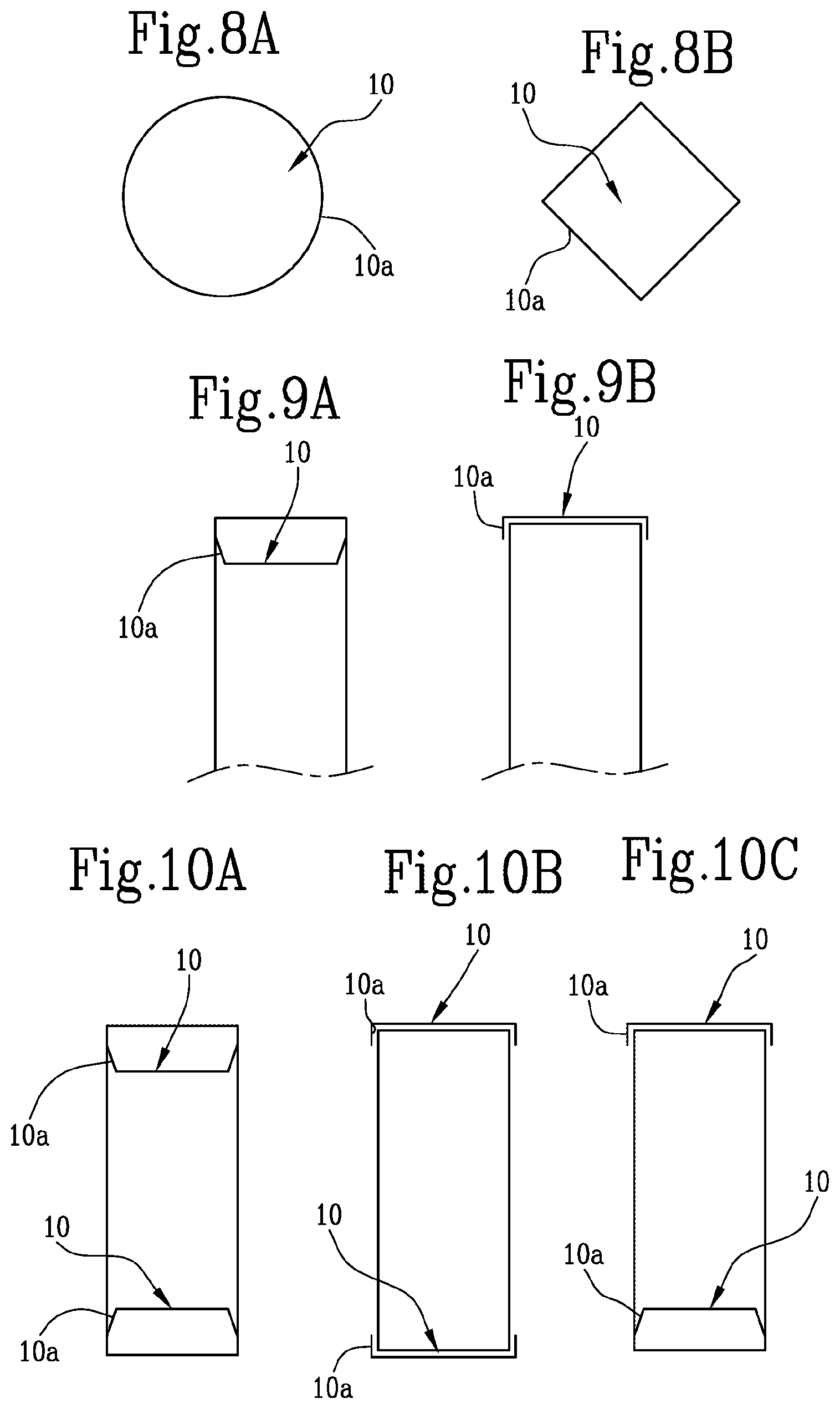
[0133] Preferably, the step of making a closing wall is performed by folding a respective end portion of the strip.
[0134] Alternatively, the step of making a closing wall is performed by folding a respective end portion of the tubular body.
[0135] Alternatively, the step of making a closing wall is performed by folding a respective end portion of the tubular body and of the strip.
[0136] Preferably, at least one end portion of the at least one tubular wrapper defines a closing circle having a plurality of fold points and the step of making a closing wall comprises a step of mechanically deforming the respective closing circle.
[0137] Preferably, the plurality of fold points comprises four fold points angularly spaced around the main axis of extension and comprising a first pair of fold points which are opposite each other relative to the main axis of extension and a second pair of fold points which are opposite each other relative to the main axis of extension.
[0138] The step of mechanically deforming therefore comprises the steps of folding the first pair of fold points towards the main axis of extension and then folding the second pair of fold points towards the main axis of extension, superposing the second pair on the first pair.
[0139] Alternatively, the step of mechanically deforming comprises a step of applying on the closing circle a pressure which is directed towards the main axis of extension on each fold point in such a way as to cause the plurality of fold points to be folded simultaneously towards the main axis of extension.
[0140] Preferably, the step of mechanically deforming comprises, before the step of applying on the closing circle a pressure coaxial to the main axis of extension, a step of preforming the closing circle by applying on each fold point a pressure capable of making a respective plurality of preforming lines disposed radially around the main axis of extension.
[0141] Still more preferably, the plurality of fold points comprises four fold points angularly spaced from each other around the main axis of extension and the step of applying on the closing circle a pressure coaxial to the main axis of extension causes the plurality of fold points to be simultaneously folded towards the main axis of extension to define a surface which is substantially cross-shaped.
[0142] Alternatively, the step of mechanically deforming comprises the steps of gripping each fold point of the plurality of folds points and applying a torque to each pair of fold points opposite to each other relative to the main axis of extension along the closing circle, finally finishing making the closing wall by applying on each fold point a pressure which is coaxial to the main axis of extension.
[0143] In particular, the step of making at least one closing wall comprises the steps of: [0144] before the step of inserting a filling material, making a first closing wall, transverse to the main axis of extension to at least partly close a first end of the at least one tubular wrapper; [0145] after the step of inserting a filling material, making a second closing wall, transverse to the main axis of extension to at least partly close a second end of the at least one tubular wrapper.
[0146] Preferably, the steps of making a first closing wall and making a second closing wall are performed by folding an end portion of a respective end of the at least one tubular wrapper.
[0147] Alternatively, one between the steps of making a first closing wall and making a second closing wall comprises the steps of preparing a rod-shaped segment of the tobacco industry and abutting a first end of the rod-shaped segment of the tobacco industry against one end of the at least one tubular wrapper.
[0148] Then the rod-shaped segment is stably connected to the at least one tubular wrapper.
[0149] Preferably, that step of stably connecting is performed by wrapping a connecting strip round the rod-shaped segment in such a way that a first portion of the connecting strip is superposed on the first end of the rod-shaped segment and a second portion is at least partly superposed on the at least one tubular wrapper, thus connecting the rod-shaped segment stably to the at least one tubular wrapper.
[0150] Advantageously, the connecting strip may be made from the same strip which defines the at least one tubular wrapper.
[0151] Alternatively, one between the steps of making a first closing wall and making a second closing wall is performed by preparing a tubular wrapper which is closed at the first end by a closing base, transverse to the main axis of extension, to at least partly close the containment chamber.
[0152] A method for making a sub-unit of a smoking article is also presented, comprising the steps of: [0153] preparing one tubular wrapper of the tobacco industry, which extends along a main axis of extension and internally has a containment chamber. [0154] The tubular wrapper has an access opening on at least one of its end portions for access to the containment chamber; [0155] inserting a filling material of the tobacco industry into the containment chamber; [0156] making a closing wall, transverse to the main axis of extension, for at least partly closing the at least one access opening. [0157] In particular, the step of making a closing wall comprises the steps of: [0158] inserting a closing element into a respective end of the tubular wrapper to define a closing wall for closing the access opening, the closing element extending transversely to the main axis of extension in such a way as to at least partly close the access opening. [0159] deforming the respective end of the tubular wrapper to make at least one blocking portion for blocking the closing element.
[0160] That step may be carried out either before or after the step of inserting the closing element.
[0161] Preferably, the method further comprises a step of deforming the respective end of the tubular wrapper to make a further blocking portion for blocking the closing element.
[0162] Still more preferably, each step of deforming the respective end of the tubular wrapper is performed by creating an edge bead or narrowing of the respective end of the tubular wrapper.
[0163] According to this invention, the containment chamber may be closed using closing walls made respectively using different methods.
[0164] In other words, it is possible to make one closing wall according to one of the two methods of this invention which are indicated above and to make another closing wall of the same tubular wrapper using a different method.
[0165] Such combinations therefore allow, for example, one wall to be made by folding a respective end of the at least one tubular wrapper and the other wall to be made by applying a closing element combined with making or not making blocking surfaces.
[0166] The steps indicated above therefore provide a method for making a sub-unit of a smoking article capable of guaranteeing correct containment of the filling material inserted in it.
BRIEF DESCRIPTION OF DRAWINGS
[0167] Further features and advantages of this invention are more apparent in the indicative non-limiting description below, with reference to a preferred, non-limiting, embodiment of a sub-unit of a smoking article and related method for making it, as illustrated in the accompanying drawings, in which:
[0168] FIGS. 1A-C show in particular cross-sections of portions of tubular wrappers according to this invention;
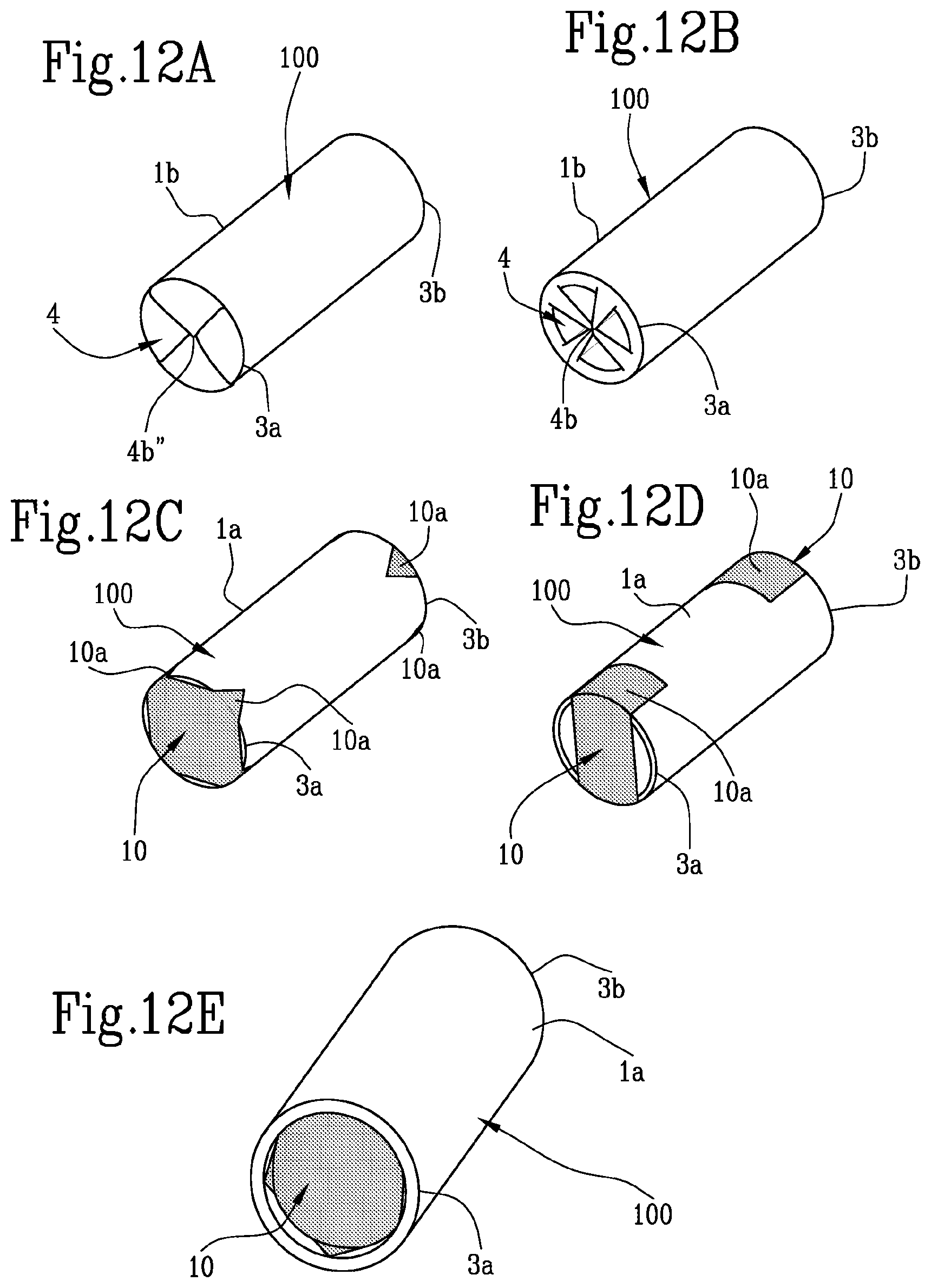
[0169] FIGS. 2A-E show in particular different embodiments of closing walls of a sub-unit of a smoking article according to a first aspect of this invention;
[0170] FIGS. 4A-G show different possible embodiments of a portion of a sub-unit of a smoking article;
[0171] FIGS. 3A-C show the surfaces of several closing walls made according to this invention;
[0172] FIGS. 5A-C show the procedural steps for making a closing wall according to one particular embodiment of this invention;
[0173] FIGS. 6A-C show the procedural steps for making a closing wall according to a further embodiment of this invention;
[0174] FIGS. 7A-C show the procedural steps for making a closing wall according to a further embodiment of this invention.
[0175] FIGS. 8A-B show in particular different embodiments of closing elements of a sub-unit of a smoking article;
[0176] FIGS. 9A-B show different relative possible embodiments of the closing wall of the sub-unit according to a further aspect of this invention;
[0177] FIGS. 10A-C show different possible embodiments of a sub-unit of a smoking article having a pair of closing elements;
[0178] FIGS. 11A-D show different relative possible embodiments of the closing wall of the sub-unit according to a further aspect of this invention;
[0179] FIGS. 12A-E are perspective views of different possible embodiments of this invention.
DETAILED DESCRIPTION OF PREFERRED EMBODIMENTS OF THE INVENTION
[0180] In the accompanying drawings the numeral 100 generally denotes a sub-unit of a smoking article, by way of example and without limiting the scope of the invention that sub-unit may be used for making a smoking article of the Heat Not Burn (HNB) type or for making an electronic cigarette or a conventional cigarette.
[0181] According to this invention, the sub-unit 100 comprises a tubular wrapper 1, shown in different possible embodiments in the accompanying FIGS. 1A-C, which extends along a main axis of extension "X" and internally defines a containment chamber 2 which contains a filling material "M" of the tobacco industry.
[0182] By way of example and without limiting the scope of the invention, that filling material "M" may be an aerosol-generating material, tobacco pellets, tobacco which is loose or in another form, flavouring material (for example micro-capsules containing a flavouring liquid) or filtering material (activated charcoal, silica gel or others known in the reference sector) or even a material with cooling effect (such as PLA pellets).
[0183] Moreover, on at least one of its ends 3a, 3b that tubular wrapper 1 comprises an access opening configured for allowing access to the containment chamber.
[0184] The tubular wrapper 1 may be made using different elements with tubular extension of the tobacco industry.
[0185] In particular, the tubular wrapper 1 is defined by a rigid tubular body 1a or by a strip 1b which is wrapped round the main axis of extension "X" in such a way as to define the tubular wrapper 1 or by both.
[0186] By way of example and without limiting the scope of the invention, for the purposes of this description, the term strip means an element having a surrounding structure which can be made using a material having a net, mesh, perforated shape, or is made from a piece of sheet material suitable for containing the filling material "M" and having particular permeability properties.
[0187] The sub-unit 100 also comprises at least one closing element 10 applied to the at least one end 3a, 3b of the tubular wrapper to define a closing wall for closing the access opening.
[0188] The closing element 10 extends transversely to the main axis of extension "X" in such a way as to at least partly close the access opening.
[0189] According to one aspect of this invention, shown in FIG. 8A, the closing element 10 has a substantially circular profile, that is to say, that it has a profile substantially following that of the tubular wrapper 1, which also preferably has a substantially circular profile.
[0190] According to a further aspect of this invention, shown in FIG. 8B, the closing element 10 has a substantially square profile.
[0191] In general terms, it should be noticed that, each closing element 10 is made of a material having high thermal conductivity at least at a portion of it which closes the access opening.
[0192] Preferably, each closing element 10 is made of flame retardant material.
[0193] In one embodiment, each closing element 10 is at least partly made of metallic or metallized material, that is to say, comprising metal particles intended to render the at least one tubular wrapper 10 unsuitable for combustion.
[0194] According to a first possible embodiment, shown in FIG. 9A, the closing element 10 is located inside the tubular wrapper 1 and is coupled to an inside surface of the respective end portion of the tubular wrapper 1.
[0195] In other words, the access opening to the containment chamber 2 is closed by inserting the closing element 10 in the tubular wrapper 1 in such a way that the closing element at least partly obstructs the access opening.
[0196] In use, the at least one closing element 10 is deformed in such a way as to define a convex surface directed towards the containment chamber 2.
[0197] That convex surface is suitable for causing the filling material "M" to be moved away from a respective access opening of the tubular wrapper 1.
[0198] In this way it is possible to guarantee that, if the sub-unit 100 is abutted against a heating element, the latter will not risk burning the filling material "M" positioned near it because it remains separated from the filling material by the closing element 10.
[0199] The closing element 10 also comprises at least one edge portion 10a by means of which the closing element 10 itself is coupled to the tubular wrapper 1.
[0200] In particular, the closing element 10 is connected to an inside wall of the end 3a, 3b of the tubular wrapper 1 by interference with the edge portion 10a.
[0201] In other words, once inserted into the containment chamber 2, the closing element 10 is deformed in such a way that its edge portion 10a is pressed against the inside wall of the end 3a, 3b into which the closing element 10 is inserted and the friction between the two prevents it from slipping out.
[0202] Alternatively, the closing element 10 may be coupled to the tubular wrapper 1 by gluing the edge portion 10a to an inside wall of the end 3a, 3b of the tubular wrapper
[0203] According to a further possible embodiment of this invention, shown in FIG. 9B, the at least one closing element 10 is applied on the outside of the tubular wrapper 1 and is coupled to an outside surface of the respective end 3a, 3b of the tubular wrapper 1.
[0204] In this case too, the closing element 10 has at least one edge portion 10a for the stable coupling between the closing element 10 and the end 3a, 3b of the tubular wrapper 1.
[0205] In particular, the closing element 10 may be coupled to the tubular wrapper 1 by gluing the edge portion 10a to an outside wall of the respective end 3a, 3b.
[0206] The closing element 10 has a surface extension such as to entirely cover the access opening and is provided with at least one hole or perforation for increasing the permeability of the closing element 10 to air or gases.
[0207] In other words, the closing element 10 does not hermetically seal the access opening, since the passage of air/gas must always be guaranteed for correct operation of the article once implemented in a finished product.
[0208] According to a different embodiment, the closing element 10 has a surface extension such as to partly cover the access opening in such a way as to define uncovered portions of the access opening intended to allow air or gas to pass through.
[0209] In other words, the closing element 10 is configured to prevent the filling material "M" from coming out of the containment chamber 2, but at the same time to guarantee the passage of a flow of air and/or gas through that chamber 2.
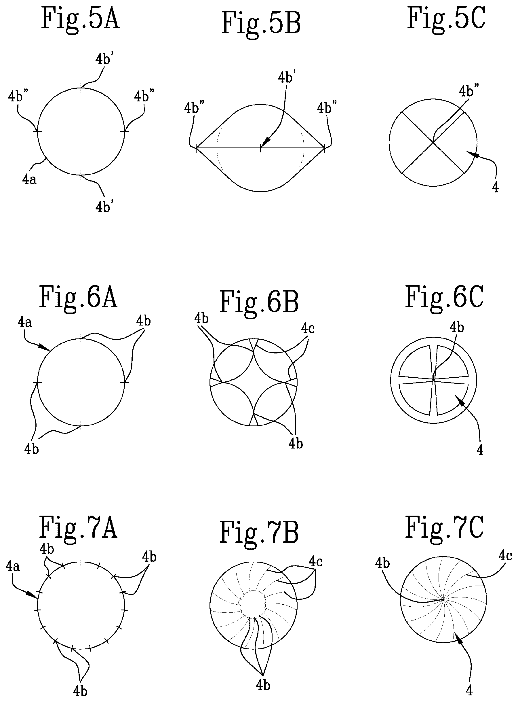
[0210] This particular characteristic is obtained either by making holes or perforations, or by applying a closing element 10 with a geometry such as to leave some portions of the access opening partly uncovered.
[0211] Moreover, it should be noticed how it is also possible to have a combination of such characteristics, that is to say, by applying to the end 3a, 3b a closing element 10 which has a surface extension such as to only partly cover the access opening and is also provided with holes or perforations for improving its air and/or gas permeability.
[0212] The closing element 10 may comprise a piece of sheet material which has at least one edge portion 10a which is suitably deformed to adapt to the shape of the end 3a, 3b of the tubular wrapper 1.
[0213] In other words, the closing element 10 is made in the form of a plate or layer, preferably elastic, capable of deforming so that it can be inserted in the tubular wrapper
[0214] According to one alternative embodiment the closing element 10 comprises a porous body.
[0215] In other words, the closing element 10 may be made of a material which is spongy or porous, suitable for being fitted in the tubular wrapper 1.
[0216] According to one particular aspect of this invention, the sub-unit 100 comprises a rod-shaped segment 5 of the tobacco industry having one end coupled and connected to a first end 3a of the tubular wrapper 1, defining a closing wall 4, transverse to the wrapping axis "X" and at least partly closing the containment chamber 2, whilst a closing element 10 is applied to a second end 3b, opposite to the first end 3a, of the tubular wrapper.
[0217] In other words, the sub-unit 100 may have at its second end 3b a closing wall 4 made according to the methods indicated above, whilst the closing wall 4 at the first end 3a is made by coupling the latter to a rod-shaped segment 5 which may for example be a segment made of filtering material, therefore suitable for making a filter of the smoking article, or a heating element configured for allowing the passage inside it of a flow of air and/or another gas and for heating it as it passes.
[0218] Preferably, the rod-shaped segment 5 is connected to the tubular wrapper 1 by a connecting strip 6 made of wrapping material which may even optionally coincide with the tubular wrapper 1.
[0219] According to one particular aspect of this invention, the rod-shaped segment 5 is at least partly inserted in the containment chamber 2 in such a way that the tubular wrapper 1 fits round the outside of an end portion of the rod-shaped segment 5.
[0220] The devices and configurations indicated above allow multiple embodiments, illustrated by way of example and without limiting the scope in the accompanying FIGS. 4A-4F.
[0221] FIG. 4A shows a single tubular wrapper 1 defined by the strip 1b with one end coupled to the rod-shaped segment 5, in this case the strip 1b defining the tubular wrapper 1 also performs the function of connecting strip 6 since it allows the tubular wrapper 1 to be connected to the rod-shaped segment 5.
[0222] FIG. 4B shows a first tubular wrapper 1 defined by the tubular body 1a and a second tubular wrapper 1 defined by the strip 1b wrapped round the tubular body 1a, the rod-shaped segment 5 being abutted against a first end 3a of the tubular body and connected to it by the action of the strip 1b which in this configuration again performs the function of connecting strip 6.
[0223] In contrast, FIG. 4C shows how the tubular body 1 is defined only by the strip 1b whilst there is a further connecting strip 6 between the strip 1b and the rod-shaped segment 5 for stably connecting them.
[0224] In contrast, FIG. 4D shows a sub-unit 100 having a first tubular wrapper 1 defined by the tubular body 1a and a second tubular wrapper 1 defined by the strip 1b wrapped round the tubular body 1a, there also being present a connecting strip 6 which connects the tubular body 1a to the rod-shaped segment 5 without being superposed on the strip 1b.
[0225] In contrast, FIG. 4E has the same configuration as FIG. 4D with partial superposing of the strip 1b on the connecting strip 6.
[0226] Finally, FIG. 4F shows only the tubular body 1a abutted against the rod-shaped segment 5 and connected to it by means of the connecting strip 6, in other words the strip 1b is not present in that embodiment.
[0227] According to a further possible embodiment, shown in FIG. 4G, the tubular wrapper 1 has a configuration which, at its first end 3a is closed by a closing base 7, transverse to the main axis of extension "X", to at least partly close the containment chamber 2, whilst a closing element 10 is applied to a second end 3b, opposite to the first end 3a, of the tubular wrapper 1.
[0228] In particular, the closing base 7 is made as one with the tubular wrapper 1 and is actually a projection of its first end 3a towards the axis of extension "X".
[0229] According to a further possible embodiment, the tubular wrapper 1 has two access openings, opposite to each other, on opposite ends 3a, 3b of the tubular wrapper 1 for access to the containment chamber 2.
[0230] According to that embodiment, the sub-unit 100 comprises two closing elements each coupled to a respective end 3a, 3b of the tubular wrapper to at least partly close the respective access opening.
[0231] As shown in the accompanying FIGS. 10A-C, it is possible to make sub-units 100 which have different shapes at their ends.
[0232] In particular, FIG. 10A shows a sub-unit 100 comprising a pair of closing elements both positioned inside the containment chamber and where the relative edge portions engage respective inside walls of the ends 3a, 3b to which the closing elements are applied.
[0233] In contrast, FIG. 10B shows a sub-unit 100 comprising a pair of closing elements both configured to engage the outside wall of the respective ends 3a, 3b to which the closing elements 10 are applied.
[0234] Finally, FIG. 10C highlights a possible embodiment which uses both solutions, since a first closing element 10 is joined to an outside wall of a respective first end 3a, whilst a second closing element 10 is joined to an inside wall of a respective second end 3b.
[0235] Below is a description of an embodiment of the sub-unit not illustrated in the figures, although hereinafter reference will be made to the numbering used for the other embodiments illustrated in order to better indicate the parts described. That sub-unit comprises: the tubular wrapper 1 which extends along the main axis of extension X and which defines the containment chamber 2 inside which the filling material M of the tobacco industry is contained, the tubular wrapper 1 having two access openings (to the containment chamber 2) at the first end 3a and at the second end 3b; and two closing elements 10 which each partly close a relative access opening of the tubular wrapper 1, engaging in the inside surface of the tubular wrapper 1.
[0236] In detail, each closing element 10 is a plate or layer made of an elastically deformable material. That plate or layer may be made of a metallic material (for example, steel). Each closing element 10, in the form of the plate or layer, has a square shape (more generally, each closing element 10 may have a polygonal shape comprising vertices; for example, it could be in the shape of a triangle, pentagon or hexagon).
[0237] Preferably, each closing element 10 is configured in such a way that the vertices of the square fit into the tubular wrapper 1 (at the inside surface of it). In other words, each closing element 10 has a predetermined thickness, a predetermined perimeter (substantially circumscribed inside the first end 3a of the tubular wrapper 1) and is made of a material having a predetermined stiffness such that when the closing element 10 is inserted into the tubular wrapper 1, the vertices of the closing element 10 partly fit into the wall of the tubular wrapper 1 and the closing elements 10 are substantially flat and orthogonal to the main axis of extension of the tubular wrapper 1.
[0238] Alternatively, for example by making one of the closing elements 10 using a more elastic material (or with reduced thickness) and with a perimeter such that it is not circumscribed in the first end 3a of the tubular wrapper 1, when inserting the closing element 10 into the tubular wrapper 1 the vertices of the closing elements 10 in any case engage in the inside surface of the tubular wrapper 1 but said closing elements 10 are concave (and not substantially flat) towards the inside of the containment chamber 2.
[0239] It should be noticed that inserting a square closing element 10 into the tubular wrapper 1 will partly close the access opening: there will be four portions of circular sectors which are open at the sides of the closing element 10. The sizing of those portions of circular sectors is such that it prevents the filling material M from coming out of the containment chamber 2; on the other hand, those portions of circular sectors advantageously allow the passage of air inside the containment chamber 2.
[0240] Moreover, in order to increase the air flow inside the containment chamber 2, the closing element 10, one or both, in the form of a plate or layer may comprise one or more holes (sized in such a way as to prevent the filling material M from coming out of the containment chamber 2). Moreover, one of those holes (for example, a central hole in the closing element 10) may be used for inserting the closing element 10 into the tubular wrapper 1.
[0241] It should be noticed that if the tubular wrapper 1 has only one access opening (at the first end 3a or the second end 3b) then the sub-unit will only be able to comprise a single closing element 10; the characteristics described above with reference to each of the closing elements 10 of the sub-unit described above are also verified.
[0242] Advantageously, this invention achieves the proposed aims by overcoming the disadvantages of the prior art by making available to the user a sub-unit 100 of a smoking article and the related method for making it which guarantee the production of high quality articles, guaranteeing correct containment of the filling material "M" inside them, preventing any accidental loss of filling material.
[0243] This invention also relates to a sub-unit 100 which comprises at least one tubular wrapper 1 which extends along a main axis of extension "X" and internally defines a containment chamber 2 containing a filling material "M" of the tobacco industry.
[0244] The sub-unit 100 comprises at least at one end 3a, 3b of it a closing wall 4, transverse to the main axis of extension "X", for at least partly closing the containment chamber 2.
[0245] In particular, the closing wall 4 is defined by folding an end portion of the respective end 3a, 3b of the at least one tubular wrapper 1.
[0246] Advantageously that shape guarantees that the filling material "M" is correctly kept inside the containment chamber 2, preventing it from accidentally coming out.
[0247] The tubular wrapper 1 may be made using different elements with tubular extension of the tobacco industry.
[0248] According to one aspect of this invention, the tubular wrapper 1 is defined by a rigid tubular body 1a.
[0249] According to a further aspect of this invention, the tubular wrapper 1 is defined by a strip 1b which is wrapped round the main axis of extension "X" in such a way as to define the tubular wrapper 1.
[0250] Advantageously, the sub-unit 100 may include both of the solutions indicated above and comprise both a rigid tubular body 1a and a strip 1b which in synergy operate in conjunction with one another to define the containment chamber 2.
[0251] Specifically, the tubular body 1a defines a first tubular wrapper 1 which delimits an inside wall of the containment chamber 2, whilst the strip 1b is wrapped round the tubular body 1a defining a second tubular wrapper 1 which delimits an outside wall of the containment chamber 2.
[0252] In the various situations outlined above, the strip 1b comprises a rubber-coated layer suitably positioned for guaranteeing that it is kept correctly in the wrapped configuration and, if necessary, for guaranteeing its stable coupling to the tubular body 1a.
[0253] The closing wall 4, as indicated above defined by an end portion of the end 3a, 3b of the at least one tubular wrapper 1, may therefore be obtained by folding a portion of the tubular body 1a, of the strip 1b or of both.
[0254] Therefore, it must be emphasized that the simultaneous presence of the tubular body 1a and of the strip 1b does not necessarily mean that both will be folded simultaneously, in fact it is possible to make a sub-unit 100 comprising both the tubular body 1a and the strip 1b but only one of the two defines the closing wall 4.
[0255] Specifically, two situations are highlighted, in the first the tubular body 1a is folded, whilst the strip 1b is only wrapped around the tubular body 1a without folds in its end part, in the second the strip 1b is folded and keeps inside it the tubular body 1a which is not folded.
[0256] Preferably, the end portion of the strip 1b and/or of the tubular body 1a intended to make the closing wall 4 is made of material which is thermally conductive or has greater thermal conductivity than the remaining part of the strip 1b and/or of the tubular body 1a.
[0257] In order to simultaneously guarantee correct containment of the filling material "M" and to guarantee optimum passage of fluid through the sub-unit 100 it is essential to precisely define the shape of the closing wall 4.
[0258] At least one end portion of one end 3a, 3b of a tubular wrapper 1 defines a closing circle 4a having a plurality of fold points 4b and the closing wall 4 is defined by mechanically deforming the closing circle 4a along that plurality of fold points 4b.
[0259] In other words, each end 3a, 3b of each tubular wrapper 1 designed to define a closing wall 4 defines a closing circle 4a which, once suitably shaped by a mechanical deformation, will create the closing wall 4.
[0260] According to one particular embodiment, the plurality of fold points 4b comprises four fold points angularly spaced around the main axis of extension "X" and divided into two separate pairs, a first pair 4b' and a second pair 4b''.
[0261] Each pair comprises two fold points 4b which are opposite each other relative to the main axis of extension "X", that is to say, a line joining the two points of each pair intersects the main axis of extension "X", and the mechanical deformation applied to the closing circle 4a causes the first pair 4b' of points to be superposed on the second pair 4b'' of points.
[0262] According to a further possible embodiment, the plurality of fold points 4b comprises four fold points equidistant along the closing circle 4a and the mechanical deformation causes the four fold points 4b to come into abutment with each other inside the containment chamber 2.
[0263] According to a third possible embodiment, the mechanical deformation causes a torsional folding of the plurality of fold points 4b around the main axis of extension "X".
[0264] Those types of processing may be applied at both ends 3a, 3b of the at least one tubular wrapper 1, in fact, according to one aspect of this invention, at each end 3a, 3b of the at least one tubular wrapper 1 the sub-unit 100 has a closing wall 4, transverse to the wrapping axis "X", for at least partly closing the containment chamber 2.
[0265] Both closing walls 4 are defined by folding an end portion of a respective end 3a, 3b of the at least one tubular wrapper 1.
[0266] Each closing wall 4 relative to one of the two end portions 3a, 3b may be made using any combination of the features described above independently of each other.
[0267] In other words, each closing wall 4 may be defined by folding only the tubular body 1a, only the strip 1b or both, without this placing any constraints on how the other closing wall is made.
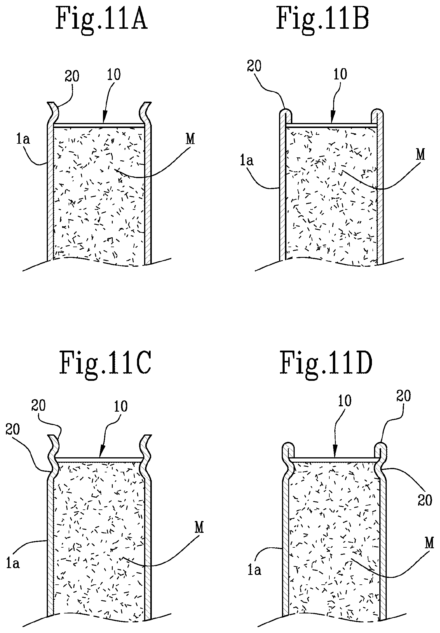
[0268] The same criterion may apply relative to the type of mechanical deformation to which the respective end 3a, 3b is subjected in order to define one of the closing walls 4, that is to say, each closing wall 4 may be made by means of any of the three deformations indicated above in an example, non-limiting way without thereby meaning that it is necessary to make the other closing wall 4 using the same deformation.
[0269] Alternatively, the sub-unit 100 comprises a rod-shaped segment 5 of the tobacco industry which has one end coupled and connected to a first end 3a of the at least one tubular wrapper 1 defining a closing wall 4, transverse to the wrapping axis "X", and at least partly closing the containment chamber 2, whilst the at least one tubular wrapper 1 has at its second end 3b, opposite to the first end 3a, a closing wall 4 defined by folding of an end portion of the second end 3b.
[0270] In other words, the sub-unit 100 may have at its second end 3b a closing wall 4 made according to the methods indicated above, whilst the closing wall 4 at the first end 3a is made by coupling the latter to a rod-shaped segment 5 which may for example be a segment made of filtering material, therefore suitable for making a filter of the smoking article, or a heating element configured for allowing the passage inside it of a flow of air and/or another gas and for heating it as it passes.
[0271] Preferably, the rod-shaped segment 5 is connected to the at least one tubular wrapper 1 by a connecting strip 6 of wrapping material which may even optionally coincide with the second tubular wrapper 1b.
[0272] According to one particular aspect of this invention, the rod-shaped segment 5 is at least partly inserted in the containment chamber 2 in such a way that the at least one tubular wrapper 1 fits round the outside of an end portion of the rod-shaped segment 5.
[0273] According to a further possible embodiment, the at least one tubular wrapper 1 has a configuration which, at its first end 3a is closed by a closing base 7, transverse to the main axis of extension "X", to at least partly close the containment chamber 2, and has at its second end 3b, opposite to the first end 3a, a closing wall 4 defined by the folding of the end portion of the second end 3b.
[0274] In particular, the closing base 7 is made as one with the tubular wrapper 1 and is actually a projection of its first end 3a towards the axis of extension "X".
[0275] In general terms, it should be noticed that each closing wall 4 is made with a portion of tubular wrapper 1 material having high thermal conductivity.
[0276] Preferably, each closing wall 4 is made of flame retardant material.
[0277] In one embodiment, each closing wall 4 is at least partly made of metallic or metallized material, that is to say, comprising metallic particles intended to render each closing wall 4 unsuitable for combustion.
[0278] Moreover, each closing wall 4 is made of material which is naturally porous or rendered porous by making holes or perforations in it, for example by means of laser, electrostatic, plasma perforation, in order to improve its air or gas permeability, for allowing correct inflow of air into the filling material "M" or outflow of smoke produced from it.
[0279] In other words, the closing wall 4 has features such that it easily allows, that it to say, without opposing it, the passage of a flow of air or gas through the closing wall 4 itself, therefore allowing that flow to reach and pass through the filling material "M" contained in the containment chamber 2.
[0280] This invention also relates to a method for making a sub-unit 100 of a smoking article, in particular a sub-unit 100 according to what is described above.
[0281] The method disclosed comprises preparing at least one tubular wrapper 1 of the tobacco industry which extends along a main axis of extension "X" and internally has a containment chamber 2.
[0282] That step may be carried out and completed by preparing a tubular body 1a of the tobacco industry.
[0283] Alternatively that step may be carried out and completed by means of the steps of preparing a strip 1b and wrapping the strip 1b round the main axis of extension "X".
[0284] According to a further aspect of this invention, the method for making a sub-unit 100 comprises the steps of preparing a tubular body 1a of the tobacco industry and a strip 1b and wrapping the strip 1b round the tubular body 1a.
[0285] In that way the tubular body 1a defines a first tubular wrapper 1 delimiting an inside wall of the containment chamber 2 and the strip 1b defines a second tubular wrapper 1 delimiting an outside wall of the containment chamber 2.
[0286] Once the containment chamber has been made it is possible to proceed with inserting a filling material "M" of the tobacco industry in that containment chamber 2.
[0287] Then, at least at one end 3a, 3b of the tubular wrapper 1, a closing wall 4 is made, transverse to the main axis of extension "X", for at least partly closing the at least one end 3a, 3b.
[0288] The step of making a closing wall 4 is performed by folding an end portion of a respective end 3a, 3b of the at least one tubular wrapper 1.
[0289] In this way it is possible, in an extremely simple way, to make a sub-unit 100 capable of guaranteeing correct containment of the filling material "M", avoiding the risk of it coming out in an unwanted and unpredictable way which compromise the structural integrity of the product and prevent it from being marketed.
[0290] Advantageously, the step of making a closing wall may alternatively be performed by folding a respective end portion of the tubular body 1a and/or of the strip 1b.
[0291] As already indicated, it is possible to fold only the tubular body 1a, only the strip 1b or both simultaneously, in such a way that together they define the closing wall 4, even if both are present.
[0292] That is to say, the first and second tubular wrapper 1 could be present simultaneously, but only one of the two is folded to make the closing wall 4.
[0293] In particular, at least one end 3a, 3b of the at least one tubular wrapper 1 defines a closing circle 4a which has a plurality of fold points 4b and the step of making a closing wall 4 comprises a step of mechanically deforming the respective closing circle 4a.
[0294] In other words, the method according to this invention comprises making a closing wall 4 for closing the containment chamber 2 of the sub-unit 100 by applying a mechanical deformation of one end 3a, 3b of the at least one tubular wrapper 1 which defines the containment chamber 2.
[0295] According to a first possible embodiment, the plurality of fold points 4b comprises four fold points 4b which are equidistant from each other, divided into two separate pairs, a first pair 4b' and a second pair 4b''.
[0296] Each pair comprises two fold points 4b which are opposite each other relative to the main axis of extension "X", that is to say a line joining the two fold points 4b of each pair intersects the main axis of extension "X", and the step of mechanically deforming comprises a first step of folding the first pair 4b' of fold points 4b towards the main axis of extension "X" and a second step of folding the second pair 4b'' of fold points 4b towards the main axis of extension, superposing it on the first pair 4b'.
[0297] In other words, after having defined the positioning of the fold points 4b along the closing circle 4a, the fold points 4b belonging to the first pair 4b' are folded towards the main axis of extension "X", then the making of the closing wall 4 is completed by folding the fold points 4b of the second pair 4b'' also towards the main axis of extension
[0298] Alternatively, the step of mechanically deforming comprises a step of applying on the closing circle 4a a pressure which is directed towards the main axis of extension "X" on each fold point 4b in such a way as to cause the plurality of fold points 4b to be folded simultaneously towards the main axis of extension "X".
[0299] Preferably, before applying on the closing circle 4a a pressure coaxial to the main axis of extension "X" the method comprises preforming the closing circle 4a by acting on each fold point 4b in such a way as to make a respective plurality of preforming lines 4c disposed radially around the main axis of extension "X".
[0300] According to a first possible embodiment, linked to this aspect the plurality of fold points 4b comprises four fold points 4b equidistant from each other and the step of applying on the closing circle 4a a pressure coaxial to the main axis of extension "X" causes the four fold points 4b to be simultaneously folded towards the main axis of extension "X" to define a surface which is substantially cross-shaped.
[0301] In other words, four fold point 4b equidistant from each other along the closing circle 4a are defined, then the closing circle 4a is preformed by making a pair of preforming lines 4c for each fold point 4b and the procedure is completed by simultaneously folding the fold points 4b towards the main axis of extension "X".
[0302] According to a second possible embodiment, again linked to the same aspect, the mechanical deformation occurs by means of the steps of gripping each fold point 4b and applying a torque to each pair of fold points 4b opposite to each other relative to the main axis of extension "X" and finally applying on each fold point 4b a pressure which is coaxial to the main axis of extension "X".
[0303] What is described above comprises closing at least one closing wall 4 of a respective end 3a, 3b of the tubular wrapper 1 since the tubular wrapper does not necessarily need to be closed at both of its ends 3a, 3b.
[0304] If that is not the case, in general terms, the step of making at least one closing wall comprises a step of making a first closing wall 4, transverse to the main axis of extension "X", and at least partly closing a first end 3a of the at least one tubular wrapper 1.
[0305] That step is preferably performed before the step of inserting a filling material "M" in the containment chamber 2 in such a way as to allow a container to be made which has a single access opening through which to insert the filling material "M".
[0306] In contrast, after the step of inserting a filling material "M", comes the step of making a second closing wall 4, which is also transverse to the main axis of extension "X", and at least partly closing a second end 3b of the at least one tubular wrapper 1.
[0307] According to a first possible embodiment both of the closing walls 4 are made by folding an end portion of a respective end 3a, 3b of the at least one tubular wrapper
[0308] Alternatively, according to a further possible embodiment, one between the steps of making a first closing wall 4 and making a second closing wall 4 comprises the steps of preparing a rod-shaped segment 5 of the tobacco industry and abutting a first end of that rod-shaped segment 5 against one end of the at least one tubular wrapper 1.
[0309] Then the rod-shaped segment 5 is stably connected to the at least one tubular wrapper 1.
[0310] In particular, that step of stably connecting comprises a step of wrapping the strip round the rod-shaped segment in such a way that a first portion of the connecting strip 6 is superposed on the first end of the rod-shaped segment 5 and a second portion is at least partly superposed on the at least one tubular wrapper 1 thus stably connecting them to each other.
[0311] According to another possible embodiment the step of making a first closing wall 4 is performed by preparing a tubular wrapper 1 which is closed at the first end 3a by a closing base 7, transverse to the main axis of extension "X", and at least partly closing the containment chamber 2.
[0312] According to a further aspect of this invention, the sub-unit 100 of a smoking article comprises a tubular wrapper 1 which extends along a main axis of extension "X" in such a way as to internally define a containment chamber 2 containing a filling material "M" of the tobacco industry.
[0313] The tubular wrapper 1 has an access opening on at least one of its ends 3a, 3b, for access to the containment chamber 2.
[0314] The sub-unit 100 also comprises at least one closing element 10 applied to a respective end 3a, 3b of the tubular wrapper 1 to define a closing wall 4 for closing the access opening.
[0315] The closing element 10 extends transversely to the main axis of extension "X" in such a way as to at least partly close the access opening.
[0316] Moreover, as shown in the accompanying FIGS. 11A-D, the end 3a, 3b to which the closing element 10 is applied has at least one blocking portion, located inside the end 3a, 3b and extending transversely to the main axis of extension "X", to define a blocking surface for blocking the closing element 10.
[0317] In particular, the at least one blocking portion 20 is defined by a permanent deformation of the respective end 3a, 3b in which the blocking portion 20 is applied.
[0318] In particular, the at least one blocking portion 20 comprises an annular ridge or narrowing on an inside surface of the respective end 3a, 3b.
[0319] Preferably, the end 3a, 3b has a pair of blocking portions 20, and the closing element 10 is interposed between the blocking portions 20 and blocked between them in a configuration of at least partial closure of the access opening.
[0320] Those blocking portions 20 may be made according to different possible embodiments, shown by way of example in FIGS. 11A-D.
[0321] In particular, according to one possible embodiment, at least one blocking portion 20 of the pair of blocking portions 20, preferably the inner one, is defined by an annular ridge.
[0322] Preferably, both of the blocking portions 20 of the pair of blocking portions 20 are defined by an annular ridge.
[0323] Alternatively, one blocking portion 20 of the pair of blocking portions 20, preferably the inner one, is defined by an annular ridge and the other blocking portion 20 is defined by an edge bead on an end portion of the end 3a, 3b.
[0324] The term narrowing refers to a mechanical working intended to circumferentially deform the tubular wrapper 1, giving it a cross-section with reduced diameter.
[0325] In other words, the outside wall of the tubular wrapper 1 is crushed along a circular path in such a way that this outside wall defines a recess.
[0326] The term edge bead refers to a mechanical working intended to fold over itself an end portion of a respective end 3a, 3b of the tubular wrapper 1, in such a way that it makes contact with an inside wall of the tubular wrapper 1 itself.
[0327] According to one preferred embodiment, the pair of blocking portions 20 has a first blocking portion 20 preferably defined by a narrowing of the tubular wrapper 1, interposed between the filling material "M" and the closing element 10, and a second blocking portion 20 preferably defined by an edge bead on the end portion of the tubular wrapper 1, interposed between the closing element 10 and an environment outside the tubular wrapper 1.
[0328] It should be noticed that, generally speaking, the presence of the blocking portion 20 interposed between the filling material "M" and the closing element 10 prevents an excessive insertion of the latter in the containment chamber.
[0329] In fact, if that were to occur, the closing element 10 could apply excessive pressure on the filling material "M", also risking invalidating its quality by making it deteriorate.
[0330] The presence of the blocking portion 20, interposed between the closing element 10 and an environment outside the tubular wrapper 1, in contrast guarantees correct containment of the filling material "M" since it prevents the closing element 10 from accidentally coming out, securely connecting it to the tubular wrapper 1.
[0331] According to one aspect of this invention the closing element 10 has a substantially circular profile, that is to say, it has a profile substantially following that of the tubular wrapper 1.
[0332] According to a further aspect of this invention the closing element 10 has a substantially square profile.
[0333] In general terms, it should be noticed that each closing element 10 is made of a material having high thermal conductivity at least at a portion of it which closes the access opening.
[0334] Preferably, each closing element 10 is made of flame retardant material.
[0335] In one embodiment, each closing element 10 is at least partly made of metallic or metallized material, that is to say, comprising metal particles intended to render each closing element 10 unsuitable for combustion.
[0336] According to a first possible embodiment, the closing element 10 is located inside the tubular wrapper 1 and is coupled to an inside surface of the respective end portion of the tubular wrapper 1.
[0337] In other words, the access opening to the containment chamber 2 is closed by inserting the closing element 10 in the tubular wrapper 1 in such a way that the closing element at least partly obstructs the access opening.
[0338] Preferably, the at least one closing element 10 is deformed in such a way as to define a convex surface directed towards the containment chamber 2.
[0339] That convex surface is suitable for causing the filling material "M" to be moved away from a respective access opening of the tubular wrapper 1.
[0340] In this way it is possible to guarantee that, if the sub-unit 100 is abutted against a heating element, the latter will not risk burning the filling material "M" positioned near it because it remains separated from the filling material by the closing element 10.
[0341] The closing element 10 also comprises at least one edge portion 10a by means of which the closing element 10 is coupled to the tubular wrapper 1.
[0342] In particular, the closing element 10 is connected to an inside wall of the end 3a, 3b of the tubular wrapper 1 by interference of the edge portion 10a with it.
[0343] Alternatively, the closing element 10 may be coupled to the tubular wrapper 1 by gluing the edge portion 10a to an inside wall of the end 3a, 3b of the tubular wrapper
[0344] Preferably, the closing element 10 has a surface extension such as to entirely cover the access opening and is provided with at least one hole or perforation for increasing the air or gas permeability of the closing element 10.
[0345] In other words, the closing element 10 does not hermetically seal the access opening, since the passage of air/gas must always be guaranteed for correct operation of the article once implemented in a finished product.
[0346] Alternatively, the closing element 10 has a surface extension such as to partly cover the access opening in such a way as to define uncovered portions of the access opening intended to allow air or gas to pass through.
[0347] According to one particular embodiment, the closing element 10 comprises a piece of sheet material having at least one edge portion which is suitably deformed to adapt to the shape of the end 3a, 3b of the tubular wrapper 1.
[0348] In other words, the closing element 10 is made in the form of an elastic plate or layer capable of deforming so that it can be inserted in the tubular wrapper 1.
[0349] According to a further possible embodiment the closing element 10 comprises a porous body.
[0350] In other words, the closing element 10 may be made of a material which is spongy or porous, suitable for being fitted in the tubular wrapper 1.
[0351] Alternatively, the sub-unit 100 comprises a rod-shaped segment 5 of the tobacco industry having one end coupled and connected to a first end 3a of the tubular wrapper 1, defining a closing wall 4, transverse to the wrapping axis "X" and at least partly closing the containment chamber 2, whilst a closing element 10 is applied to a second end 3b, opposite to the first end 3a, of the tubular wrapper.
[0352] Moreover, the end 3b to which the closing element 10 is applied, has at least one blocking portion, transverse to the main axis of extension "X", extending from a wall of the tubular wrapper 1 towards the main axis of extension "X" to define a blocking surface for blocking the closing element 10.
[0353] In other words, the sub-unit 100 may have at its second end 3b a closing wall 4 made according to the methods indicated above, whilst the closing wall 4 at the first end 3a is made by coupling the latter to a rod-shaped segment 5 which may for example be a segment made of filtering material, therefore suitable for making a filter of the smoking article, or a heating element configured for allowing the passage inside it of a flow of air and/or another gas and for heating it as it passes.
[0354] Preferably, the rod-shaped segment 5 is connected to the tubular wrapper 1 by a connecting strip 6 made of wrapping material which may even optionally coincide with the tubular wrapper 1.
[0355] According to one particular aspect of this invention, the rod-shaped segment 5 is at least partly inserted in the containment chamber 2 in such a way that the tubular wrapper 1 fits round the outside of an end portion of the rod-shaped segment 5.
[0356] According to a further possible embodiment, the tubular wrapper 1 has a configuration which, at its first end 3a is closed by a closing base 7, transverse to the main axis of extension "X", to at least partly close the containment chamber 2 whilst a closing element 10 is applied to a second end 3b, opposite to the first end 3a, of the tubular wrapper 1.
[0357] Moreover, the end 3b to which the closing element 10 is applied, has at least one blocking portion 20, transverse to the main axis of extension "X", extending from a wall of the tubular wrapper 1 towards the main axis of extension "X" in such a way as to define a blocking surface for blocking the closing element 10.
[0358] In particular, the closing base 7 is made as one with the tubular wrapper 1 and is actually a projection of its first end 3a towards the axis of extension "X".
[0359] According to a further possible embodiment, the tubular wrapper 1 has two access openings, opposite to each other, on opposite ends 3a, 3b of the tubular wrapper 1 for access to the containment chamber 2.
[0360] According to that embodiment, the sub-unit 100 comprises two closing elements 10 each coupled to a respective end 3a, 3b of the tubular wrapper to at least partly close the respective access opening.
[0361] Moreover, both of the ends 3a, 3b to which the closing elements 10 are applied have at least one respective blocking portion 20, transverse to the main axis of extension "X", extending from a wall of the tubular wrapper 1 towards the main axis of extension "X" to define a blocking surface for blocking the respective closing element
[0362] This invention also relates to a method for making a sub-unit 100 of a smoking article which comprises preparing a tubular wrapper 1 of the tobacco industry which extends along a main axis of extension "X" and internally has a containment chamber 2.
[0363] The tubular wrapper 1 also has an access opening on at least one of its ends 3a, 3b for access to the containment chamber.
[0364] The method therefore comprises a step of inserting a filling material "M" of the tobacco industry into the containment chamber 2.
[0365] A closing wall is then made, transverse to the main axis of extension "X", for at least partly closing the at least one access opening.
[0366] Specifically, relative to the particular embodiment described in more detail here, the step of making a closing wall in turn comprises a series of steps which comprise inserting a closing element 10 into a respective end 3a, 3b of the tubular wrapper 1.
[0367] As already indicated, that closing element 10 is configured to define a closing wall 4 for closing the at least one access opening.
[0368] The closing element 10 extends transversely to the main axis of extension "X" in such a way as to at least partly close the above-mentioned access opening.
[0369] Then the respective end 3a, 3b of the tubular wrapper 1 is deformed in such a way as to make a blocking surface for blocking the closing element 10.
[0370] According to one aspect of this invention, the step of making a closing wall is performed in two steps for making a pair of blocking portions, that is to say, the method described here comprises two deforming steps on a respective end 3a, 3b of the tubular wrapper in such a way as to make a blocking surface for blocking the closing element
[0371] Those steps may both be performed after inserting the closing element 10 in the containment chamber 2, in such a way that first the closing element 10 is inserted and then the two blocking portions 20 are made such that they contain the closing element 10 between them, stably connecting it and preventing it from slipping out of the containment chamber 2.
[0372] Alternatively, according to a further possible embodiment, it is possible to make a first blocking portion 20 before inserting the closing element 10, in such a way as to supply in a simple and efficient way a supporting surface for the closing element 10 during its positioning in the containment chamber 2 in such a way as to simplify that procedure.
[0373] Then, that is to say, once the closing element 10 is correctly inserted in the containment chamber, a second blocking portion 20 can be made for blocking the closing element 10.
[0374] It should be noticed how each of the above-mentioned steps of deforming the respective end 3a, 3b of the tubular wrapper may be performed by creating an edge bead on or by narrowing the respective end 3a, 3b of the tubular wrapper 1.
[0375] Those embodiments may advantageously be applied even in combination with each other on different ends 3a, 3b of the same tubular wrapper 1.
[0376] Therefore, it is possible to make a first closing wall 4 by folding a respective end of the at least one tubular wrapper 1 and to make the other wall by applying a closing element 10 combined with the presence or absence of the blocking portions 20.
[0377] Therefore, advantageously, it is possible to make combinations such that they optimize the particular production process within which the method described above is implemented or to improve the quality of the end product within which the sub-unit 100 according to this invention is inserted.
* * * * *
D00000
D00001
D00002
D00003
D00004
D00005
D00006
XML
uspto.report is an independent third-party trademark research tool that is not affiliated, endorsed, or sponsored by the United States Patent and Trademark Office (USPTO) or any other governmental organization. The information provided by uspto.report is based on publicly available data at the time of writing and is intended for informational purposes only.
While we strive to provide accurate and up-to-date information, we do not guarantee the accuracy, completeness, reliability, or suitability of the information displayed on this site. The use of this site is at your own risk. Any reliance you place on such information is therefore strictly at your own risk.
All official trademark data, including owner information, should be verified by visiting the official USPTO website at www.uspto.gov. This site is not intended to replace professional legal advice and should not be used as a substitute for consulting with a legal professional who is knowledgeable about trademark law.