Water Filter For An Aquarium
Jankiewicz; Janusz ; et al.
U.S. patent application number 17/050185 was filed with the patent office on 2021-04-08 for water filter for an aquarium. The applicant listed for this patent is Aquael Janusz Jankiewicz SP. Z O.O.. Invention is credited to Jerzy Brzeski, Janusz Jankiewicz, Stanislaw Konter.
| Application Number | 20210100224 17/050185 |
| Document ID | / |
| Family ID | 1000005300927 |
| Filed Date | 2021-04-08 |


| United States Patent Application | 20210100224 |
| Kind Code | A1 |
| Jankiewicz; Janusz ; et al. | April 8, 2021 |
Water Filter For An Aquarium
Abstract
Exemplary embodiments relate to a water filter for an aquarium that includes a housing, a cover, a removable first and second body, and an actuator. The housing includes an interior area configured to house filtration cartridges and an opening closable by the cover. The first body is configured to be in operative fluid connection with a water inlet and the second body is configured to be in operative fluid connection with the housing interior area through the cover, and is operatively releasably engageable therewith. The first and second bodies are releasably engageable in fluid tight connection, and each include a valve in operative connection therewith. The actuator is in operative connection with at least one of the valves and operation thereof is operative to simultaneously change each valve between the respective open and closed positions.
| Inventors: | Jankiewicz; Janusz; (Warszawa, PL) ; Brzeski; Jerzy; (Raszyn, PL) ; Konter; Stanislaw; (Warszawa, PL) | ||||||||||
| Applicant: |
|
||||||||||
|---|---|---|---|---|---|---|---|---|---|---|---|
| Family ID: | 1000005300927 | ||||||||||
| Appl. No.: | 17/050185 | ||||||||||
| Filed: | April 25, 2019 | ||||||||||
| PCT Filed: | April 25, 2019 | ||||||||||
| PCT NO: | PCT/IB2019/053417 | ||||||||||
| 371 Date: | October 23, 2020 |
| Current U.S. Class: | 1/1 |
| Current CPC Class: | A01K 63/045 20130101 |
| International Class: | A01K 63/04 20060101 A01K063/04 |
Foreign Application Data
| Date | Code | Application Number |
|---|---|---|
| Apr 26, 2018 | PL | P425372 |
Claims
1. (canceled)
2. (canceled)
3. (canceled)
4. (canceled)
5. (canceled)
6. (canceled)
7. (canceled)
8. (canceled)
9. (canceled)
10. (canceled)
11. (canceled)
12. (canceled)
13. (canceled)
14. Apparatus comprising: a water filter configured for fluid connection with an aquarium, wherein the water filter comprises a housing, wherein the housing includes a base and side walls that bound a housing interior area, and an opening to enable access to the housing interior area, wherein the housing interior area is configured to house a plurality of filtration cartridges, wherein the filtration cartridges are operative to remove particles from fluid passing therethrough, a cover, wherein the cover is releasable engageable with the housing and is operative to close the housing opening, wherein the cover includes in operatively attached connection therewith, a fluid inlet, a removable first body, a removable second body, wherein the first body is in operative fluid connection with the fluid inlet, wherein the first body includes a first valve, wherein the second body is in operative fluid connection with the housing interior area, wherein the second body includes a second valve, wherein the first body and the second body are releasably engageable in fluid tight relation, wherein when the first body and the second body are operatively engaged in fluid tight relation, the first valve and the second valve are in operative fluid connection, and the first valve and the second valve are each changeable between an open position and a closed position, an actuator, wherein the actuator is in operative connection with at least one of the first valve arid the second valve, wherein the first valve and the second valve are in operative connection such that operation of the actuator is operative to cause each of the first valve and the second valve to simultaneously change between their respective open and respective closed positions.
15. The apparatus according to claim 14 wherein the first valve and the second valve each include a gear segment in operative connection therewith, wherein when the first body and the second body are operatively engaged in fluid tight relation, the first valve gear segment and the second valve gear segment are operatively engaged.
16. The apparatus according to claim 15 wherein the second body includes a locking projection in fixed operative connection therewith, wherein when the first valve gear segment and the second valve gear segment are operatively engaged, the locking projection is operatively radially disposed between an outer toothed portion of the first valve gear segment and an axis of rotation of the first valve gear segment.
17. apparatus according to claim 16 wherein the first valve gear segment includes a first cam, wherein the second valve gear segment includes a second cam, wherein in the engaged position of the first and second valve gear segments and in the closed positions of the first and second valves, the first cam and the second cam are operatively engaged such that the first body and the second body are in operatively aligned relation.
18. The apparatus according to claim 17 wherein in the engaged position of the first and second valve gear segments and in the open position of the first and second valves, the locking projection is in operatively blocking relation with a radially inner surface of the first valve gear segment immediately adjacent the outer toothed portion such that the first body and the second body cannot be fluidly disengaged.
19. The apparatus according to claim 18 wherein during operation of the actuator operative to change the first and second valves from the closed position to the open position, the first cam and the second cam change from an operatively engaged position to a disengaged position.
20. The apparatus according to claim 19 wherein during operation of the actuator operative to change the first and second valves from the open position to the closed position, the first cam and the second cam change from the disengaged position to the operatively engaged position.
21. The apparatus according to claim 20 wherein the actuator comprises a manually rotatable lever, wherein in the engaged position of the first and second valve gear segments and in the closed position of the first and second valves, manual rotation of the lever in a first lever direction is operative to cause each of the first and second valves to change from the respective closed position to the respective open position.
22. The apparatus according to claim 21 wherein the first body or the second body that includes the valve with the manually rotatable lever in operative connection therewith includes a lever stop in operative connection with such body, wherein the lever stop is operative to prevent the lever from being rotated in the first lever direction beyond a position corresponding to the open position of the valves.
23. The apparatus according to claim 22 wherein the first body or the second body that includes the lever stop includes a further lever stop in operative connection therewith, wherein the further lever stop is operative to prevent the lever from being rotated in a second lever direction opposed of the first lever direction beyond a position corresponding to the closed position of the valves.
24. The apparatus according to claim 23 wherein at least one of the first valve and the second valve comprises a rotary valve.
25. The apparatus according to claim 24 wherein at least one of the first valve and the second valve comprises a ball valve.
26. The apparatus according to claim 24 wherein the cover further includes a roughing filter chamber, wherein the roughing filter chamber is in operative fluid connection with the second valve and the housing interior area, wherein the roughing filter chamber is fluidly intermediate of the second valve and the housing interior area.
27. The apparatus according to claim 26 wherein the cover further includes at least one check valve, wherein the at least one check valve is operatively positioned fluidly intermediate of the second valve and the roughing filter chamber.
28. The apparatus according to claim 27 wherein the at least one check valve comprises a first movable closing flap and a second movable closing flap, wherein the first and second movable closing flaps permit fluid flow from the second valve to the roughing filter chamber, and wherein the first and second movable closing flaps prevent backflow of fluid from the roughing filter chamber to the second valve.
29. The apparatus according to claim 28 wherein each of the filtration cartridges is operatively removably positioned in a respective filtration cartridge container, and wherein each of the filtration cartridge containers is operatively removably positioned within the housing interior area.
30. The apparatus according to claim 29 wherein the cover further includes in operatively attached connection therewith, a fluid outlet, a further removable first body, a further removable second body, wherein the further first body is in operative fluid connection with the fluid outlet, wherein the further first body includes a further first valve, wherein the further second body is in operative fluid connection with the housing interior area, wherein the further second body includes a further second valve, wherein the further first body and the further second body are releasably engageable in fluid tight relation, wherein when the further first body and the further second body are operatively engaged in fluid tight relation, the further first valve and the further second valve are in operative connection, and the further first valve and the further second valve are each changeable between an open position and a closed position, a further actuator wherein the further actuator is in operative connection with at least one of the further first valve and the further second valve, wherein the further first valve and the further second valve are in operative connection such that operation of the actuator is operative to cause each of the further first valve and the further second valve to simultaneously change between their respective open position and respective closed position.
31. The apparatus according to claim 1 wherein the first valve and the second each include a gear segment in operative connection therewith, wherein when the first body and the second body are operatively engaged in fluid tight relation, the first valve gear segment and the second valve gear segment are operatively engaged, wherein at least one of the first body and the second body includes a locking projection in fixed operative connection therewith, wherein when the first valve gear segment and the second valve gear segment are operatively engaged, the locking projection is operatively radially disposed between an axis of rotation and an outer toothed portion of the gear segment of the valve that is included on the other of the first body and the second body that does include the locking projection.
32. The apparatus according to claim 31 wherein in the engaged position of the first and second valve gear segments and in the open position of the first and second valves, the locking projection is in operatively blocking relation with a radially inner surface of the gear segment of the valve that is included on the other of the first body and the second body that does not include the locking projection, and is immediately adjacent the outer toothed portion thereof, such that the first body and the second body cannot be fluidly disengaged.
33. Apparatus comprising: a water filter configured for fluid connection with an aquarium, wherein the water filter comprises a housing, wherein the housing bounds a housing interior area that includes an enable access thereto, wherein the housing interior area is configured to house a plurality of filtration cartridges, wherein the filtration cartridges are operative to remove particles from fluid passing therethrough, a removable cover, wherein the removable cover is configured to close the housing opening, a fluid inlet, a removable first body, a removable second body, wherein the first body is configured to be in operative fluid connection with the fluid inlet, wherein the first body is configured to be in operative releasably engageable fluid tight connection with the second body, wherein the second body is configured to be in operative releasably engageable fluid tight connection with the cover, wherein when the second body is operatively engaged with the cover, the second body is in operative fluid connection with the housing interior area through the cover, wherein the first body includes a first movable valve element, wherein the second body includes a second movable valve element, wherein the first movable valve element and the second movable valve are each changeable between a respective open position and a respective closed position, wherein in the respective open position of each of the first and second movable valve elements, fluid is enabled to flow past the first and second movable valve elements and through the first body and the second body, wherein in the respective closed position of each of the first and second movable valve elements, fluid is prevented from flowing through the first body and the second body, a manually engageable lever, wherein the lever is in operative fixed connection with at least one of the first movable valve element and the second movable valve element, and wherein manual rotation of the lever is operative to cause each of the first movable valve element and the second movable valve element to simultaneously change between their respective open position and respective closed position.
Description
TECHNICAL FIELD
[0001] The exemplary embodiments relate to a water filter for an aquarium. Exemplary embodiments further relate to a water filter used in external water filtration systems in aquaria for fish farming and in waterholes.
BACKGROUND
[0002] In general, in external filters for purification of water in aquaria and waterholes, contaminated water is introduced into the filter and passes a sequence of levels and types of filtration and then, upon purification, it is guided back to the water reservoir in fluid communication with the filter.
[0003] As a general rule, such filters constitute separate, i.e. external, components of equipment of an aquarium, positioned close to the aquarium or waterhole with which they operate. Such filters are connected to water circulation effected in them by means of conduits which are arranged within connection ports secured within the cover of the filter. These ports constitute entrance elements of water inlet and water outlet arrangements in the filter, and are provided with valves. During removal of the connection ports from the cover, for example, for washing and periodic inspection or servicing of the filter components, the valves housed therein have to remain in their closed position. Changes in the valve position front open to closed and vice versa, are effected most frequently by an additional activating element, for example by a lever.
[0004] Water filters for aquaria and waterholes may benefit from improvements.
SUMMARY
[0005] An exemplary water filter for an aquarium according to exemplary embodiments comprises a housing in the form of a container that has an open top. The exemplary housing includes filtration cartridges arranged therein and a cover secured to the housing. The exemplary cover includes, operatively arranged therein, a priming arrangement and removable connection ports of water inlet and water outlet arrangements. The exemplary water inlet and water outlet arrangements are provided with valves. The exemplary water inlet comprises a first valve and a second valve, while the exemplary water outlet arrangement comprises a first valve and a second valve. The exemplary first valves and exemplary second valves are coupled by an exemplary drive transmission mechanism.
[0006] In exemplary embodiments, the exemplary first valves and the exemplary second valves are rotary valves.
[0007] In exemplary embodiments, the exemplary first valves and the exemplary second valves are ball valves.
[0008] In exemplary embodiments, the exemplary first valve comprises a body and is connected to a connection port and arranged in the filter cover.
[0009] In exemplary embodiments, the exemplary second valve comprises a body and is fixed within the cover, downstream the first valve, at the connection port positioned in the cover.
[0010] In exemplary embodiments, the exemplary drive transmission mechanism is a gear transmission mechanism.
[0011] In exemplary embodiments, the exemplary drive transmission mechanism comprises a rotatable (also referred to herein as an actuator) lever with a rack (also referred to herein as a gear segment) and a cooperating toothed wheel (also referred to herein as a gear segment). The exemplary lever with the rack is seated in a bearing in the body of the first valve and the toothed wheel is seated in a bearing in the body of the second valve.
[0012] In exemplary embodiments, the exemplary body of the first valve is surrounded by a jacket in which an opening for lever rotation is formed.
[0013] In exemplary embodiments, the exemplary body of the second valve has a locking plug, formed above the toothed wheel, which in the position of a connection port inserted within the cover is arranged above the envelope of the rack.
[0014] In exemplary embodiments, the exemplary filter has a chamber of a roughing filter, which is formed within the cover, separately relative to the position of the water inlet and water outlet arrangements within the cover.
[0015] In exemplary embodiments, the exemplary water inlet arrangement has at least one check valve which is arranged downstream the water inlet arrangement and upstream the chamber of the roughing filter.
[0016] In exemplary embodiments, the exemplary at least one check valve comprises check valves comprised of a first closing flap and a second closing flap.
[0017] In exemplary embodiments, the exemplary filtration cartridges are arranged in containers.
[0018] The exemplary embodiments relate to an exemplary double construction of valves in the water inlet and water outlet arrangements that significantly enhances the comfort of use of the filter. The exemplary embodiments relate to an external water filter for purification of water in an aquarium that eliminates splashing of water during detachment of connection ports. The exemplary embodiments have also unexpectedly produced an exemplary arrangement that includes two valves in the inlet and outlet water circulation arrangement which makes it possible to use an additional filtration chamber formed in the cover, i.e. above the main filtration cartridges heretofore arranged exclusively within the filter housing.
BRIEF DESCRIPTION OF THE DRAWINGS
[0019] FIG. 1 shows a perspective view of an exemplary water filter for an aquarium according to the exemplary embodiments.
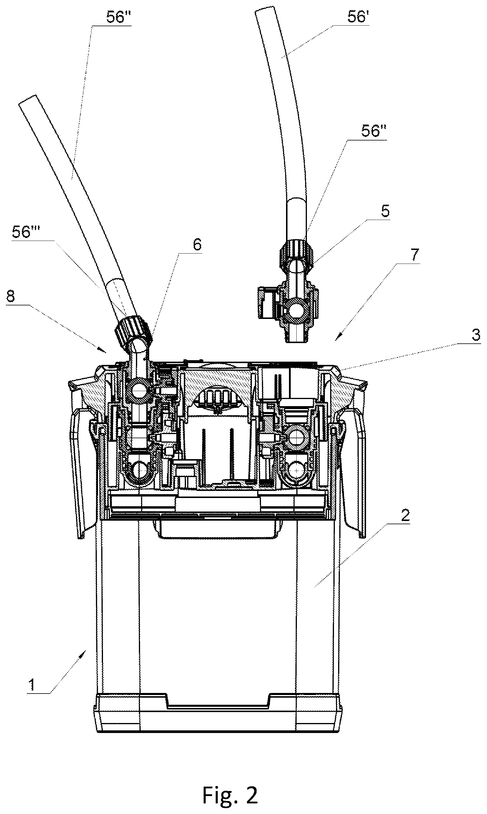
[0020] FIG. 2 shows a partial simplified cross-sectional view of an exemplary filter illustrating exemplary water inlet and exemplary water outlet arrangements.
[0021] FIG. 3 shows a perspective view of exemplary valves used in water inlet and water outlet arrangements.
[0022] FIG. 4 shows a cross-sectional view of exemplary valves used in water inlet and water outlet arrangements.
[0023] FIGS. 5a-b show exemplary valve arrangements, correspondingly in an exemplary operational mode (open position of the valves) and an exemplary mode with the exemplary connection port in a detached position (closed position of the valves).
[0024] FIG. 6 shows a detailed cross-sectional view illustrating an exemplary water inlet arrangement and an exemplary chamber of a roughing filter.
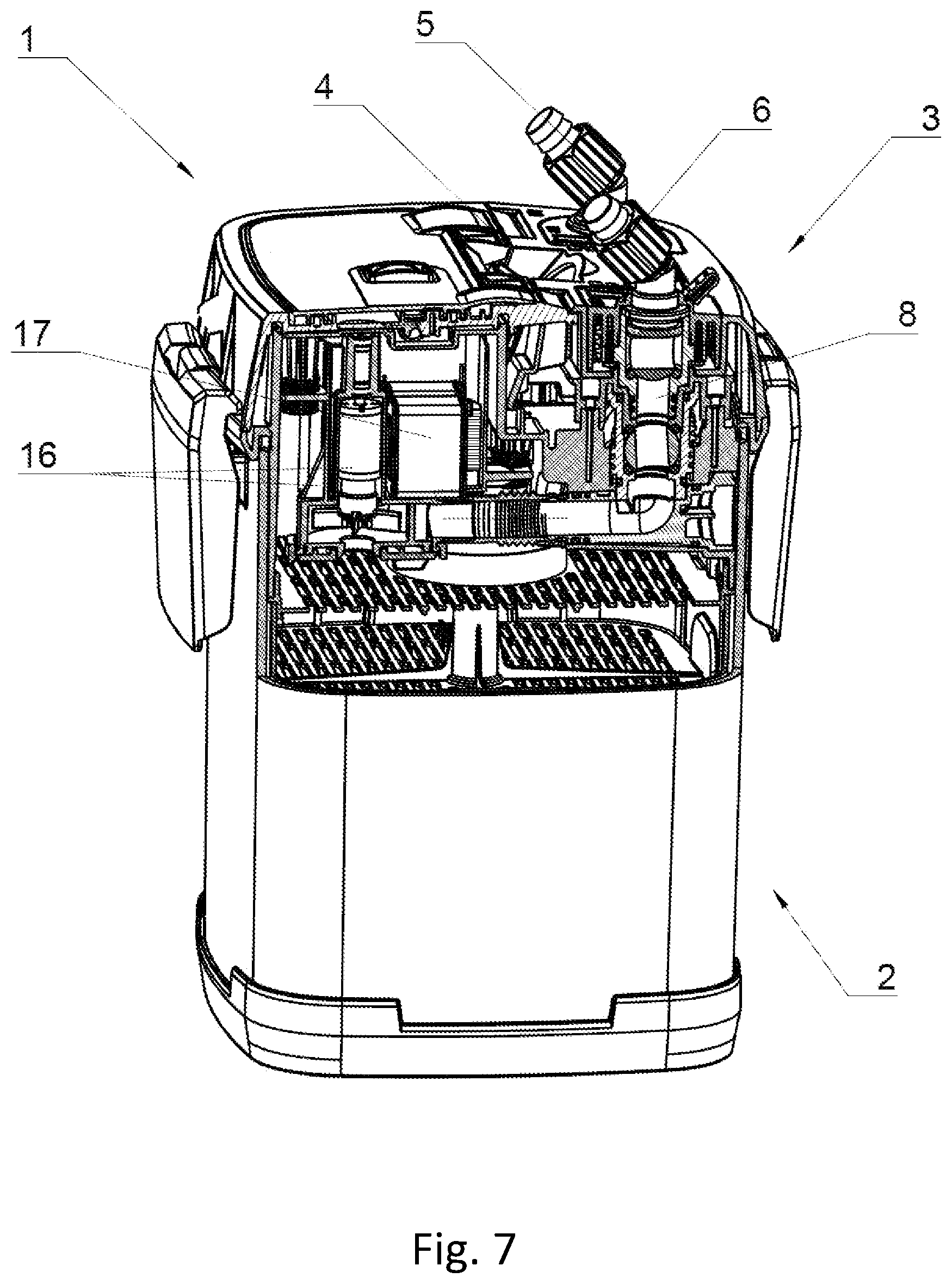
[0025] FIG. 7 shows a detailed cross-sectional view illustrating an exemplary water outlet arrangement.
DETAILED DESCRIPTION
[0026] Exemplary arrangements may include certain prior art structures. For example, document US 2003164324 A1 discloses an external filter for water purification in an aquarium encompassing a housing with filtration cartridges and a cover secured thereto, and provided with connection ports for water conduits from and to an aquarium reservoir. Both connection ports, i.e. the inlet port and the outlet port, respectively, are connected to each other in one module and they comprise ball valves. Upon detachment of the module from the filter cover, the valves in the ports are also removed. A change in the operation mode of the inlet and outlet valves, i.e. from the opened operation mode to the closed operation mode and vice versa, is effected concurrently by means of an articulated joint formed with the ports in the module. The document US 2003164324 A1 is incorporated herein by reference in its entirety.
[0027] Another example of structures for an external filter for water purification that may be used in exemplary arrangements in an aquarium is disclosed in the document US 2015048017 A1. Connection ports are connected to the corresponding valves and they are together secured in a body that may be removed from a cover. The operational mode of the valves is changed concurrently by means of an activating arrangement with a rotatable handle. The document US 2015048017 A1 is incorporated herein by reference in its entirety.
[0028] These examples of external filters for water purification in an aquarium lack a solution to prevent burdensome splashing of water from the filter during detachment of the connection ports from the cover by a user.
[0029] The exemplary embodiments presented herein relate to an exemplary improved construction of an external water filter for an aquarium, in which, during detachment of connection ports from the cover, no splashing of water from the filter occurs, which overcomes the problems associated with the prior art external filters. The exemplary embodiments include additional improvements over the prior art as well.
[0030] As shown in FIG. 1 an exemplary water filter 1 for an aquarium encompasses a housing 2 and a cover 3 secured thereto, with, seated thereon, a piston of a priming arrangement 4 (also referred to herein as a priming pump). The exemplary filter 1 further includes connection ports 5, 6 of water inlet 7 and water outlet 8 arrangements. The exemplary connection ports 5 and 6 are detachable from the cover 3.
[0031] According to exemplary embodiments, the exemplary housing 2 is formed as a vertical canister type container that is open at its top. The exemplary housing 2 includes a housing interior area that is configured to house a plurality of filtration cartridges that are operatively arranged therein, and which may be standard filtration media, such as for example, activated carbon or foam cartridges. The exemplary filtration cartridges are operatively positioned in exemplary removable containers 2' that (as shown in FIG. 6 or 7) may be operatively removably arranged within the housing 2, one above another to form a vertical pattern of sequenced levels of filtration cartridges.
[0032] FIG. 2 shows a partial and simplified cross-sectional view of an exemplary filter 1 illustrating the structure and reciprocal positioning of the exemplary cover 3 of the exemplary water inlet 7 and water outlet 8 arrangements. The exemplary removable connection ports 5, 6 are operatively releasably mounted to the cover 3 for the water inlet 7 and water outlet 8 arrangements, respectively. The mentioned ports 5, 6 are connected to a water draining conduit 56' (also referred to herein as a fluid inlet) and a water feeding conduit 56'' (also referred to herein as a fluid outlet), from and to the reservoir of an aquarium or a waterhole (not show where the filter 1 operates. For better connection of the exemplary conduits 56', 56'', the connection ports 5, 6 (according to FIG. 3) are terminated with pressure nuts 56'''.
[0033] The exemplary water inlet 7 and exemplary water outlet 8 arrangements each have an identical exemplary construction in which the water inlet 7 and the water outlet 8 each include a removable first body and a removable second body and two ball valves. The first body includes a first valve or a first movable valve element, and the second body includes a second valve or a second movable valve element. The structure and operation mode of the first body and the second body and their respective valves are illustrated in detail in FIGS. 3, 4 and 5a and 5b. Due to the exemplary constructional correspondence of the removable bodies and their respective valve arrangements, the exemplary structure of the water inlet 7 arrangement and the water outlet 8 arrangement will be presented below through a detailed description of an exemplary embodiment of the exemplary water inlet 7 arrangement only. It should be understood that the water outlet 8 has an identical exemplary construction, with the only difference being that it's first body is in operative fluid connection with the fluid outlet, as opposed to the fluid inlet, which is in operative fluid connection with the first body of the water inlet 7. Wherefor, analogous constructive elements within the valve assemblies, use identical reference signs.
[0034] According to FIGS. 3 and 4, in a first body 92 of the exemplary connection port 5. 6, an exemplary first valve 9 is defined. An exemplary ball 91 (also referred to herein as the first movable valve element) of the exemplary first valve 9 is arranged within the body 92, and is seated from the inside on a sleeve of the connection port 5, 6, and from the outside it is surrounded by a jacket 93. The exemplary connection port 5, 6 with the first valve 9 is operatively positioned within the cover 3 in a removable manner. The lower end of the body 92 protruding below the jacket 93 portion is operatively releasably engageable with, or coupled with, in fluid tight relation, the upper section of the conduit of the water inlet 7 arrangement (or the water outlet 8 arrangement), i.e. with the second body 102 that includes the second ball valve, or second valve 10, which within the cover 3 of the filter 1 is surrounded from the top by a jacket 103 secured in the cover 3. The first valve 9 and the second valve 10 are changeable between respective valve open positions and respective valve closed positions. In the open positions of the first valve 9 and the second valve 10, the movable valve elements, for example balls 91 and 101, are operatively positioned such that fluid is enabled to flow past the movable valve elements and to flow through the first body 92 and the second body 102. In the closed position of the first valve 9 and the second valve 10, the movable valve elements do not permit fluid to flow past the valve elements and through the first and second bodies.
[0035] In exemplary embodiments, the removable first body 92 is in operative fluid connection with the fluid inlet 56' and includes the first valve 9. The removable second body 102 is in operative fluid connection with the housing interior area through the cover 3 and includes the second valve 10. The first body 92 and the second body 102 are configured to be operatively releasably engageable in fluid tight relation in which the first valve 9 and the second valve 10 are in operative fluid connection. When the first body 92 and the second body 102 are operatively engaged in fluid tight relation, the fluid inlet 56' and the housing interior area are in operative fluid connection when the first valve 9 and the second valve 10 are changed from the respective valve closed positions to the respective valve open positions.
[0036] The reciprocal coupling, or simultaneous movement of the position of the exemplary valves and balls 91, 101 thereof is effected by means of a gear drive transmission mechanism 11 (also referred to herein as an actuator mechanism). According to exemplary embodiments, the exemplary drive transmission mechanism comprises a manually engageable rotatable lever 111 (also referred to herein as an actuator). The exemplary first valve 9 includes a gear a rack 112 (also referred to herein as a first valve gear segment) in fixed operative connection therewith that cooperates in operatively engaged relation with a toothed wheel 113 in operative connection with the second valve 10 (also referred to herein as the second valve gear segment). The exemplary lever 111 with the exemplary rack 112 is seated in a bearing in the body 92 of the first valve 9, while the exemplary toothed wheel 113 is seated in a bearing correspondingly in the body 102 of the second valve 10. The exemplary first valve gear segment 112 is rotatable about an axis of rotation 3C) that extends through the center of the first valve bearing. Upon positioning of the exemplary first body 92 of the connection port 5, 6 in operatively engaged fluid tight relation with the second body 10 2, and upon positioning of the second body in operatively engaged fluid tight relation e cover 3 of the filter 1, coupling or operative engagement of the rack 112 with the toothed wheel 113 occurs.
[0037] Rotation of the exemplary lever 111 in a first rotational direction and in an opposed rotational direction, effected within a longitudinal opening 94 in the jacket 93 of the first valve 9. allows for concurrent or simultaneous change in the operating position of the first valve 9 and the second valve 10 and their respective valve element balls 91, 101. The exemplary longitudinal opening 94 includes a lever stop 24 that is operative to prevent the lever 111 from being rotated in the first lever direction beyond a position corresponding to the open position of the valves. The exemplary longitudinal opening 94 also includes a further lever stop 26 that is operative to prevent the lever 111 from being rotated in a second lever direction opposed of the first lever direction beyond a position corresponding to the closed position of the valves. Thereby, the actuator 111 allows for a concurrent or simultaneous change in the operational modes of the valves, i.e. from an open valve position into a closed valve position and vice versa. It should be understood that the exemplary actuator 111 and stops 24 and 26 may be in operative fixed connection with the rack 112 of the first valve 9 and the first body 92, or the exemplary actuator 111 and stops 24 and 26 may be in operative fixed connection with the toothed wheel 113 of the second valve 10 and the second body 102.
[0038] As shown in FIG. 5, the exemplary second body 102 of the second valve 10 has an exemplary locking plug or projection 114 formed above the toothed wheel 113. When the first valve gear segment 112 and the second valve gear segment 113 are operatively engaged, the locking projection 114 is operatively radially disposed in an area between an outer toothed portion of the first valve gear segment and the axis of rotation 30 thereof. In other words, the position of the exemplary connection port 5, 6 arranged within the cover 3, the exemplary locking plug 114 is positioned above a surface which bounds the area which corresponds to the envelope of the rack 112. Rotation of the lever 111 from a closed position to the open position of the valves 9, 10 causes locking of the rack 112 under the locking plug 114, and as a result it is not possible to remove the connection ports 5, 6 during operation of the filter, nor is it possible to fluidly disengage the first body 92 and the second body 102 in an open position of both the first valve 9 and the second valve 10. Only rotation of the exemplary lever 111 back to the closed position of the valves 9, 10 allows to obtain the initial position of the rack 112 dative to the toothed wheel 113, and thereby to release the envelope of the rack 112 from beneath the locking plug 114 positioned above. In other words, in the engaged position of the first valve gear segment 112 and the second valve gear segment 113, and in the open position of the first valve 9 and the second valve 10, the locking projection 114 is in operatively blocking relation with a radially inner surface 28 of the first valve gear segment 112 adjacent the outer toothed portion such that the first body 92 the second body 102 cannot be fluidly disengaged, as shown in FIG. 5a. It should be understood that in some arrangements of a locking plug and an associated gear segment or envelope may be included on either of the body 92 or the body 102.
[0039] As shown in FIGS. 5a and 5b, the exemplary rack 112 includes a first cam 20 and the exemplary toothed wheel 113 includes a second cam 22. In order to operatively engage the exemplary first body 92 and the second body 102, the first cam 20 and the second cam have to be in operatively aligned relation such that at the instance of engagement of the first body 92 and the second body 102, the first cam 20 engages the second cam 22 in abutting relation, as would be shown in FIG. 5b if the body 92 were to be moved further downward to engage the body 102. As a result of the arrangement of the first cam 20 and the second cam 22, the rack 112 and the toothed wheel 113 will only operate to change the valves between the open position and the closed position if the first body 92 and the second body 102 are engaged in operatively aligned relation with the cams in operatively abutting engaged relation.
[0040] As such, in the engaged position of the exemplary first valve gear segment 112 and the second valve gear segment 113, and in the closed positions of the first valve 9 and the second valve 10, the first cam 20 and the second cam 22 are operatively engaged such that the first body 92 and the second body 102 are in operatively aligned relation. Further, during operation of the actuator I 11 that is operative to change the first valve 9 and the second valve 10 from the closed position to the open position, the first cam 20 and the second cam 22 change from an operatively engaged position to a disengaged position, as shown in FIG. 5a. Still further, during operation of the actuator 111 that is operative to change the first valve 9 and the second valve 10 from the open position to the closed position, the first cam 20 and the second cam 22 change from the disengaged position to the operatively engaged position, as shown in FIG. 5b if the body 92 were moved further downward to engage the body 102.
[0041] Due to the concurrent change in the position of the exemplary first valve 9 and the exemplary second 10 valve, when detaching the exemplary connection ports 5, 6, both the first valve 9 and the second valve 10 will be always set in a closed position. Due to the fact that water circulation in the filter is cut-off by the closed second valve 10, during detachment of the connection ports 5, 6 water will not be splashed.
[0042] The above discussed exemplary water inlet 7 and exemplary water outlet 8 arrangements show the same construction with regard to the valve assembly. Hereinbelow the exemplary water inlet 7 and exemplary water outlet 8 arrangements are described from the point of view of the functions performed by them and cooperation with other exemplary modules of the exemplary filter 1 of the exemplary embodiments.
[0043] According to the exemplary embodiments shown, in the cover 3 of the filter 1 there is arranged, separately from the position of the water inlet 7 and water outlet 8 arrangements, an exemplary additional filtration chamber 12 which is intended to carry out mechanical rough filtration inside. The exemplary roughing filter chamber 12 is fluidly intermediate of the second valve 10 and the housing interior area. As shown in FIG. 6, the water inlet 7 arrangement is connected to the exemplary roughing filter chamber 12 by means of an outlet opening 13 formed in the rear wall of the roughing filter chamber 12. Additionally, the water inlet 7 arrangement cooperates with a priming arrangement 4 (not shown). Upstream of the exemplary roughing filter chamber 12, the water inlet 7 arrangement is equipped with two check valves to prevent water backflow during priming the filter 1. The at least one check valve is fluidly intermediate of the second valve 10 in the roughing filter chamber 12. The check valves are constituted by a first movable closing flap 14 and a second movable closing flap 15, that both permit fluid flow from the second valve 10 to the roughing filter chamber 12 and prevent backflow of water from the roughing filter chamber 12 to the second valve 10. When introduced into the roughing filter chamber 12, water is guided next, by means of an outlet opening (not shown) formed for this purpose in the chamber to filtration cartridges, arranged in containers 2', positioned in the housing 2 of the filter 1.
[0044] As shown in FIG. 7, water finally filtered inside the housing 2 is drawn by a pump 16, driven by a motor 17 and directed to a water outlet 8 arrangement terminated in a connection port 6, and then it is guided through a draining conduit 56'' to a reservoir (not shown).
[0045] It should be clear that the exemplary embodiments are not limited to the above presented arrangements and that diverse modifications and developments thereof are possible.
[0046] Thus, the exemplary embodiments achieve improved operation, eliminate difficulties encountered in the use of prior art devices and systems, and obtain the useful results described herein.
[0047] In the foregoing description, certain terms have been used for brevity, clarity, and understanding. However, no unnecessary limitations are to be implied therefrom because such terms are used for descriptive purposes only and are intended to be broadly construed. Moreover, the description and illustrations herein are by way of examples only, and the new and useful concepts are not limited to the features shown and described.
[0048] It should be understood that features and/or relationships associated with one embodiment can be combined with features and/or relationships from another embodiment. That is, various features and/or relationships from various embodiments can be combined in further embodiments. The inventive scope of the disclosure is not limited to only the embodiments shown or described herein.
[0049] Having described the features, discoveries, and principles of the exemplary embodiments, the manner in which they are constructed and operated, and the advantages and useful results attained, the new and useful features, devices, arrangements, parts, combinations, systems, equipment, operations, methods, processes, and relationships are set forth in the appended claims.
* * * * *
D00000
D00001
D00002
D00003
D00004
D00005
D00006
D00007
XML
uspto.report is an independent third-party trademark research tool that is not affiliated, endorsed, or sponsored by the United States Patent and Trademark Office (USPTO) or any other governmental organization. The information provided by uspto.report is based on publicly available data at the time of writing and is intended for informational purposes only.
While we strive to provide accurate and up-to-date information, we do not guarantee the accuracy, completeness, reliability, or suitability of the information displayed on this site. The use of this site is at your own risk. Any reliance you place on such information is therefore strictly at your own risk.
All official trademark data, including owner information, should be verified by visiting the official USPTO website at www.uspto.gov. This site is not intended to replace professional legal advice and should not be used as a substitute for consulting with a legal professional who is knowledgeable about trademark law.