Electrolyte For Electrochemical Capacitor
Rustomji; Cyrus Sam ; et al.
U.S. patent application number 17/006851 was filed with the patent office on 2021-04-01 for electrolyte for electrochemical capacitor. The applicant listed for this patent is SOUTH 8 TECHNOLOGIES, INC.. Invention is credited to Jungwoo Lee, James Royer, Cyrus Sam Rustomji.
| Application Number | 20210098204 17/006851 |
| Document ID | / |
| Family ID | 1000005077628 |
| Filed Date | 2021-04-01 |


| United States Patent Application | 20210098204 |
| Kind Code | A1 |
| Rustomji; Cyrus Sam ; et al. | April 1, 2021 |
ELECTROLYTE FOR ELECTROCHEMICAL CAPACITOR
Abstract
Novel electrolytes, and techniques for making and devices using such electrolytes, which are based on compressed gas solvents are disclosed. Unlike conventional electrolytes, the disclosed electrolytes are based on "compressed gas solvents" mixed with various salts, referred to as "compressed gas electrolytes." Various combinations of salt and solvents are disclosed to increase performance of electrochemical capacitors using liquefied gas electrolytes.
| Inventors: | Rustomji; Cyrus Sam; (La Jolla, CA) ; Lee; Jungwoo; (San Diego, CA) ; Royer; James; (San Diego, CA) | ||||||||||
| Applicant: |
|
||||||||||
|---|---|---|---|---|---|---|---|---|---|---|---|
| Family ID: | 1000005077628 | ||||||||||
| Appl. No.: | 17/006851 | ||||||||||
| Filed: | August 30, 2020 |
Related U.S. Patent Documents
| Application Number | Filing Date | Patent Number | ||
|---|---|---|---|---|
| 62911505 | Oct 7, 2019 | |||
| 62908515 | Sep 30, 2019 | |||
| 62911508 | Oct 7, 2019 | |||
| Current U.S. Class: | 1/1 |
| Current CPC Class: | H01G 11/60 20130101; H01G 11/32 20130101; H01G 11/62 20130101 |
| International Class: | H01G 11/60 20060101 H01G011/60; H01G 11/62 20060101 H01G011/62; H01G 11/32 20060101 H01G011/32 |
Claims
1. An electrochemical capacitor device, comprising: an ionically conducting electrolyte comprising a mixture of a compressed gas solvent and one or more solid or liquid salts, wherein the compressed gas solvent comprises at least a first component that has a vapor pressure above 100 kPa at a room temperature of 293.15 K and the first component is selected from the group consisting of fluoromethane, difluoromethane, 1,1-difluoroethane, trifluoromethane, fluoroethane, trifluoroethane, tetrafluoroethane, pentafluoroethane, fluoroethylene, difluoroethylene, trifluoroethylene, tetrafluoroethylene, chloromethane, chloroethane, chloroethene, and isomers and combinations thereof; and wherein the one or more salts is selected from the group consisting of spiro-(1,1')-bipyrrolidinium tetrafluoroborate, dimethylpyrrolidinium tetrafluoroborate, ethylmethylpyrrolidinium tetrafluoroborate, diethylpyrrolidinium tetrafluoroborate, dipropylpyrrolidinium tetrafluoroborate, and dibutylpyrrolidinium tetrafluoroborate and isomers and combinations thereof; a housing enclosing the ionically conducting electrolyte under a pressurized condition to maintain the compressed gas solvent at a pressure higher than 100 kPa at a room temperature of 293.15 K; and at least two conducting electrodes in contact with the ionically conducting electrolyte.
2. The electrochemical capacitor of claim 1, wherein one or both electrodes are composed of a carbon material selected from the group consisting of: activated carbon, graphite, carbon black, graphene, and carbon nanotubes.
Description
1.0 CROSS-REFERENCE TO RELATED APPLICATIONS
[0001] The present application claims priority to U.S. Provisional Application 62/908,515 filed Sep. 30, 2019, to U.S. Provisional Application 62/911,505 filed Oct. 7, 2019, and to U.S. Provisional Application 62/911,508 filed Oct. 7, 2019. Each of these applications is incorporated by reference in their entirety.
[0002] This application is also related to U.S. application Ser. No. 16/666,155 filed Oct. 28, 2019, to PCT/US2019/032413 filed May 15, 2019, to U.S. Provisional Application No. 62/673,792 filed May 18, 2018, to U.S. application Ser. No. 16/666,131 filed Oct. 28, 2019, to PCT/US2019/032414 filed May 15, 2019, to U.S. Provisional Application No. 62/673,752 filed May 18, 2019, to U.S. Provisional Application No. 62/749,046 filed Oct. 22, 2018, to U.S. Provisional Application No. 61/972,101 filed Mar. 28, 2014, to U.S. Provisional Application No. 61/905,057 filed Nov. 15, 2013, to PCT/US14/066015 filed Nov. 17, 2014, to U.S. application Ser. No. 15/036,763 filed May 13, 2016, to U.S. application Ser. No. 16/793,190 filed Feb. 18, 2020, to PCT/US17/29821 filed Apr. 27, 2017, to U.S. application Ser. No. 16/305,034 filed Nov. 28, 2018, to U.S. Provisional Application No. 62/342,838 filed May 27, 2016, to PCT/US2020/026086 filed Apr. 1, 2020, and to U.S. Provisional Application No. 62/800,955 filed Feb. 4, 2019. The contents of each of these applications are hereby incorporated by reference in their entirety.
2.0 STATEMENT REGARDING FEDERALLY SPONSORED R&D
[0003] None
3.0 FIELD OF THE INVENTION
[0004] Embodiments of the invention relate to compositions and chemical formulations of electrolytes for use in electrochemical energy devices, such as batteries and electrochemical capacitors. Devices using the compositions and methods of use of the compositions are also provided.
4.0 BACKGROUND
[0005] Electrochemical energy storage devices, such as batteries and double layer capacitors, utilize an ionic conducting electrolyte solution to carry charge between positive and negative electrodes. Typically, these electrolytes are a liquid at a standard room temperature of +20.degree. C. and at a standard pressure (approximately 1.01325 bar). The electrolyte solutions use a mixture of some amount of solvent and salt and additional components.
[0006] Electrochemical energy storage devices, such as electrochemical capacitors, suffer from performance degradation at high voltages and high temperatures. Undesirable decomposition occurs with unstable electrolyte solvents or salts, which degrades device performance when under high voltage or high temperature. Typically, a common electrolyte, such as 1.0 M TEABF4 in acetonitrile solvent, will be limited to -40 to +65.degree. C. and 2.7 V. Reaching lower temperatures of -60.degree. C. and temperatures as high as +85.degree. C. or voltages higher than 3.0 V without degradation is highly desirable. To do so requires advancements in electrolyte solvent and salt formulations.
5.0 SUMMARY
[0007] Embodiments of the present disclosure relate to chemical formulations, electrolyte compositions, electrochemical capacitors of use thereof, and methods of use thereof. Some disclosed embodiments relate to novel formulations for electrolytes comprising a liquefied gas solvent. Disclosed herein are electrolyte formulations for electrochemical capacitors that improve the low-temperature, high-temperature, and high-voltage performance of cells.
[0008] One embodiment relates to a electrochemical capacitor that includes: an ionically conducting electrolyte comprising one or more liquefied gas solvents and one or more salts; a housing enclosing the ionically conducting electrolyte and being structured to provide a pressurized condition to the liquefied gas solvent; and at least two conducting electrodes in contact with the ionically conducting electrolyte.
[0009] In some embodiments, the liquefied gas solvent is capable of being placed under a compressive pressure equal to, or greater than, the liquefied gas solvent's vapor pressure at a temperature when the compressive pressure is applied, thereby keeping the liquefied gas solvent in a liquid phase. In some embodiments, the liquefied gas solvent has a vapor pressure above an atmospheric pressure of 100 kPa at a room temperature of 293.15 K. Embodiments of the present disclosure relate to chemical formulations, electrolyte compositions, electrochemical devices using thereof, and methods of use thereof. Some disclosed embodiments relate to novel formulations for electrolytes comprising a liquefied gas solvent.
[0010] Additional aspects, alternatives and variations, as would be apparent to persons of skill in the art, are also disclosed herein and are specifically contemplated as included as part of the invention. The invention is set forth only in the claims as allowed by the patent office in this or related applications, and the following summary descriptions of certain examples are not in any way to limit, define or otherwise establish the scope of legal protection.
6.0 BRIEF DESCRIPTION OF THE DRAWINGS
[0011] FIG. 1 illustrates the structure of several salts that may be used in the present invention.
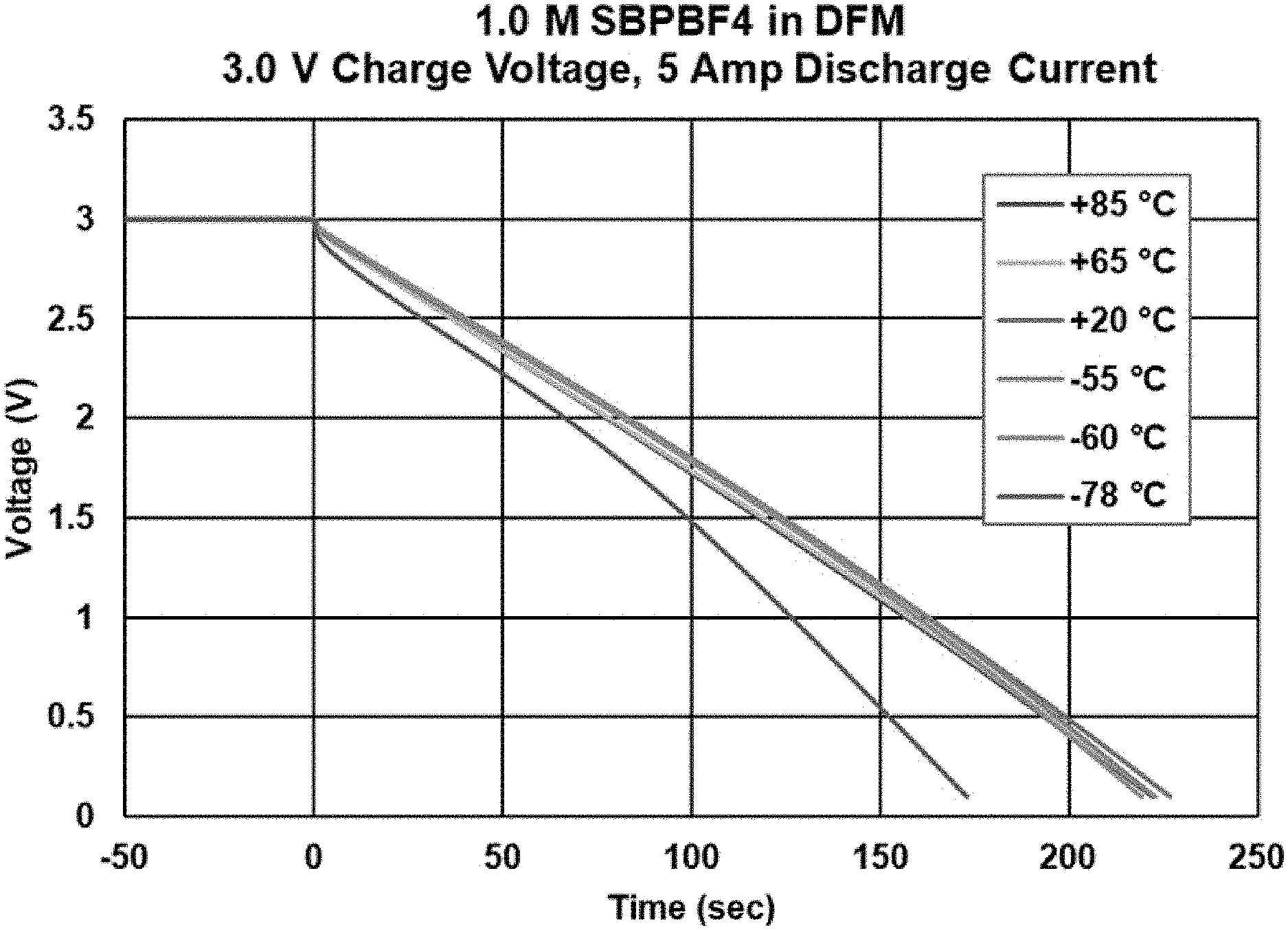
[0012] FIG. 2 illustrates the discharge curves at various temperatures for an electrochemical device composed of 1.0 M SBPBF4 in difluoromethane.
[0013] FIG. 3 illustrates the capacitance vs. discharge rate for an electrochemical device composed of 1.0 M SBPBF4 in difluoromethane at various temperatures.
[0014] FIG. 4 illustrates the capacitance vs. time for an electrochemical device composed of 1.0 M SBPBF4 in difluoromethane, which was held at 2.7 V at +85.degree. C. for 1500 hrs.
[0015] FIG. 5 illustrates the DCR resistance vs. time for an electrochemical device composed of 1.0 M SBPBF4 in difluoromethane, which was held at 2.7 V at +85.degree. C. for 1500 hrs.
[0016] FIG. 6 illustrates the capacitance vs. discharge rate for an electrochemical device composed of 1.0 M TBABF4 in difluoromethane at various temperatures.
[0017] FIG. 7 illustrates the capacitance vs. discharge rate for an electrochemical device composed of 0.3 M TEABF4 and 0.7 M TBABF4 in difluoromethane at various temperatures.
[0018] FIG. 8 illustrates the capacitance vs. discharge rate for an electrochemical device composed of 0.3 M TEABF4 in difluoromethane at +20.degree. C.
6.0 DETAILED DESCRIPTION
[0019] Reference is made herein to some specific examples of the present invention, including any best modes contemplated by the inventor for carrying out the invention. Examples of these specific embodiments are illustrated in the accompanying figures. While the invention is described in conjunction with these specific embodiments, it will be understood that they are not intended to limit the invention to the described or illustrated embodiments. To the contrary, they are intended to cover alternatives, modifications, and equivalents as may be included within the spirit and scope of the invention as defined by the appended claims.
[0020] In the following description, numerous specific details are set forth in order to provide a thorough understanding of the present invention. Particular example embodiments of the present invention may be implemented without some or all of these specific details. In other instances, process operations well known to persons of skill in the art have not been described in detail in order not to obscure unnecessarily the present invention. Various techniques and mechanisms of the present invention will sometimes be described in singular form for clarity. However, it should be noted that some embodiments include multiple iterations of a technique or multiple mechanisms unless noted otherwise. Similarly, various steps of the methods shown and described herein are not necessarily performed in the order indicated, or performed at all in certain embodiments. Accordingly, some implementations of the methods discussed herein may include more or fewer steps than those shown or described. Further, the techniques and mechanisms of the present invention will sometimes describe a connection, relationship or communication between two or more entities. It should be noted that a connection or relationship between entities does not necessarily mean a direct, unimpeded connection, as a variety of other entities or processes may reside or occur between any two entities. Consequently, an indicated connection does not necessarily mean a direct, unimpeded connection, unless otherwise noted.
[0021] It is preferred to increase the voltage and capacity of electrochemical capacitors to maximize the energy stored in the device. In addition, the device must operate over a wide range of temperatures and have good high-power (fast charge or fast discharge) properties. While acetonitrile, an organic liquid, mixed with a TEABF4 (tetraethyl ammonium tetrafluoroborate) salt is most commonly used as an electrolyte for electrochemical capacitors, the device is commonly limited to 2.7 V and -40 to +65.degree. C. temperature operation. Previously disclosed was a novel liquefied gas solvent, difluoromethane, mixed with various salts and shown to operate over a wide temperature range down to -60.degree. C.; however, high temperature was limited to +65.degree. C., and did not have good high-power performance due to poor salt solubility and diffusion within the solvent.
[0022] Disclosed herein are previously undisclosed salts to be used in combination with liquefied gas electrolytes. Salts such as spiro-(1,1')-bipyrrolidinium or dimethylpyrrolidinium tetrafluoroborate show excellent solubility in liquefied gas electrolytes, notably difluoromethane, of at least 2.0 M as measured in various experiments. It would have been otherwise impossible to determine that the solubility of these salts in liquefied gas electrolytes was considerably higher than the common salts without careful experimentation. The unexpectedly high solubility is thought to be due to the unique structure of the cation, which has two ethyl groups joined together to make a highly soluble cation. It is seen that this type of structure on the cation can greatly improve the solubility in difluoromethane and in other liquefied gas solvents. Although the increase in solubility for these salts in traditional liquid solvents has been disclosed before, never has anybody attempted to check the solubility in a liquefied gas electrolyte as disclosed here. Further, the smaller size and molecular mass of the cation over the common tetraethylammonium cation allow for higher conductivity in the electrolyte and higher cell capacitance, as it allows access to even smaller nanopores inside the carbon electrode. Using these salts in an electrochemical capacitor device led to unexpectedly high performance over a broad temperature range from -60 to +85.degree. C. with excellent charge and discharge rates and capacity retention. Previous work with common salts, such as tetraethylammonium tetrafluoroborate and tetrabutylammonium tetrafluoroborate, showed poor power performance at low temperatures. This is due to salt precipitation at these low temperatures. In contrast, the unexpectedly high solubility of spiro-(1,1')-bipyrrolidinium tetrafluoroborate or dimethylpyrrolidinium tetrafluoroborate allows for still very good performance at low temperatures. This performance would have impossible to determine without careful experimentation. Further, the cell with spiro-(1,1')-bipyrrolidinium tetrafluoroborate or dimethylpyrrolidinium tetrafluoroborate shows an unexpectedly excellent life under accelerated life testing at 2.7 V and +85.degree. C., which is unattainable in conventional electrochemical capacitors. Although in conventional liquid-based electrolytes (ex. acetonitrile) these salts have shown improved voltage 3.0 V at +65.degree. C., none have been shown to have the simultaneous capability to operate at 2.7 V at a high temperature of +85 C and maintain high power at a low temperature as low as -60.degree. C. This indicated surprisingly favorable results for the stability of both the salt and the solvent system.
[0023] In one embodiment, the electrochemical energy storage device relates to an electrochemical capacitor. In some embodiments, the electrochemical capacitor may also include a housing that encloses two conducting electrodes and the ionically conducting electrolyte. In some embodiments, the liquefied gas solvent has a vapor pressure above an atmospheric pressure of 100 kPa at a room temperature of 293.15 K. In some such embodiments, the liquefied gas solvent may be capable of being placed under a compressive pressure equal to, or greater than, the liquefied gas solvent's vapor pressure at a temperature when the compressive pressure is applied, thereby keeping the liquefied gas solvent in a liquid phase.
[0024] In some embodiments, one or both of the conducting electrodes can be composed of carbon material such as activated carbon, graphite, carbon black, graphene, carbon nanotubes. Additionally, electrodes may contain binder material such as PVDF, SBR, CMC, PTFE. Electrodes may be coated on current collector material such as aluminum, copper, nickel, titanium. The current collector may be a foil, a mesh, or a foam type material.
[0025] In some embodiments, the electrochemical device is an electrochemical energy storage device such as an electrochemical capacitor as described in PCT/US2014/066015, PCT/US2017/29821, PCT/US2019/032414, and PCT/US2019/032413.
[0026] In one embodiment, the liquefied gas solvent comprises of difluoromethane. In another embodiment, the liquefied gas solvent comprises fluoromethane. In another embodiment, the liquefied gas solvent comprises 1,1-difluoroethane. In another embodiment, the liquefied gas solvent comprises a mixture of fluoromethane and difluoromethane. In another embodiment, the liquefied gas solvent comprises a mixture of 1,1-difluoroethane and difluoromethane. In another embodiment, the liquefied gas solvent comprises a mixture of fluoromethane and 1,1-difluoroethane. In another embodiment, the liquefied gas solvent comprises a mixture of fluoromethane, difluoromethane, and 1,1-difluoroethane. The ratio of the two component mixed solvent system can be about 99:1, 98:2, 95:5, 90:10, 80:20, 70:30, 60:40, 50:50, 40:60, 30:70, 20:80, 10:90, 5:95, 2:98, 1:99 by weight of any two liquefied gas solvents fluoromethane, difluoromethane, and 1,1-difluoroethane. The ratio of the three-component mixed solvent system can be about 1:1:1, 1:2:2, 1:3:3, 2:1:2, 2:2:1, 1:2:3, 1:3:2, 2:3:2, 1:3:3 for the three liquefied gas solvents fluoromethane, difluoromethane, and 1,1-difluoroethane.
[0027] In some embodiments, the one or more salts can be comprised of those with positively charged cations such as tetramethylammonium, tetraethylammonium, tetrapropylammonium, tetrabutylammonium, triethylmethylammonium ammonium, spiro-(1,1')-bipyrrolidinium, 1,1-dimethylpyrrolidinium, and 1,1-diethylpyrrolidinium paired with negatively charged anions such as acetate, bis(fluorosulfonyl)imide, bis(oxalate)borate, bis(trifluoromethanesulfonyl)imide, bromide, chloride, dicyanamide, diethyl phosphate, hexafluorophosphate, hydrogen sulfate, iodide, methanesulfonate, methyl-phophonate, tetrachloroaluminate, tetrafluoroborate, and trifluoromethanesulfonate.
[0028] In one embodiment, the salt is composed of spiro-(1,1')-bipyrrolidinium tetrafluoroborate (SBPBF4), having the structure (1). In another embodiment, the salt is composed of dimethylpyrrolidinium tetrafluoroborate (DMPBF4) having the structure (2). In another embodiment, the salt is composed of ethylmethylpyrrolidinium tetrafluoroborate (EMPBF4) having the structure (3). In another embodiment, the salt is composed of diethylpyrrolidinium tetrafluoroborate (DEPBF4) having the structure (4). In another embodiment, the salt is composed of dipropylpyrrolidinium tetrafluoroborate (DPPBF4) having the structure (5). In another embodiment, the salt is composed of dibutylpyrrolidinium tetrafluoroborate (DBPBF4) having the structure (6). In another embodiment, the salt is composed of tetraethylammonium tetrafluoroborate (TEABF4), having the structure (7). In another embodiment, the salt is composed of tetrabutylammonium tetrafluoroborate (TBABF4), having the structure (8). In another embodiment, the salt is composed of tetrabutylammonium hexafluorophosphate (TBAPF6), having the structure (9). These nine structures are shown in FIG. 1.
[0029] In another embodiment, any of the positively charged cations used in salts (1)-(9) may be used with a plurality of negatively charged anions such as acetate, bis(fluorosulfonyl)imide, bis(oxalate)borate, bis(trifluoromethanesulfonyl)imide, bromide, chloride, dicyanamide, diethyl phosphate, hexafluorophosphate, hydrogen sulfate, iodide, methanesulfonate, methyl-phophonate, tetrachloroaluminate, tetrafluoroborate, and trifluoromethanesulfonate.
[0030] The salt in the liquefied gas solvent can be about 0.001, 0.01, 0.1, 0.2, 0.3, 0.4, 0.5, 0.6, 0.7, 0.8, 1.0, 1.1, 1.2, 1.3, 1.4, 1.5, 1.6, 1.7, 1.8, 1.9, 2.0, 2.5, or 3 molar concentration. In another embodiment, the one or more salt can be used at any such concentration to form an electrolyte with a salt mixture. In one embodiment, this could be 0.7 M SBPBF4 and 0.3M TEABF4 in difluoromethane. In another embodiment, this could be 0.5 M SBPBF4 and 0.5 M TBABF4 in difluoromethane. In another embodiment, this could be 0.3 M SBPBF4 and 0.7 M TBAPF6 in difluoromethane. In another embodiment, this could be 1.0 M SBPBF4 in difluoromethane. In another embodiment, this could be 1.0 M TBAPF6 in difluoromethane. In another embodiment, this could be 0.3 M TEABF4 in difluoromethane. In another embodiment, this could be 1.0 M DMPBF4 in difluoromethane.
[0031] Alternative or additional embodiments described herein provide an electrolyte composition comprising one or more of the features of the foregoing description or of any description elsewhere herein.
[0032] Alternative or additional embodiments described herein provide a device comprising one or more of the features of the foregoing description or of any description elsewhere herein.
[0033] Alternative or additional embodiments described herein provide a method of using the electrolyte composition or device comprising one or more of the features of the foregoing description or of any description elsewhere herein.
[0034] One of skill in the art will understand that the terms "one or more salts," "one or more solvents" (including "liquefied gas solvents" and "liquid solvents"), and "one or more additives," as used herein in connection with "the ionically conducting electrolytes," can refer to one or to a plurality of electrolyte components.
6.1 Example 1
[0035] An electrochemical capacitor device was tested with a liquefied gas electrolyte composed of 1.0 M SBPBF4 in difluoromethane (DFM). The device was charged to 3.0 V for 60 minutes and was discharged at a rate of 5 A at various temperatures. It performed well from +85.degree. C. to -55.degree. C. with little change in capacitance or impedance over that temperature range. It showed some capacitance loss at lower temperatures of -78.degree. C., yet still showed superior performance at low temperatures when compared to state-of-art electrochemical capacitors. Most surprising is the ability for the capacitor to perform well at 3.0 V and +85.degree. C. for short amounts of time. This unexpected performance is superior to that of state-of-art capacitors, which show rapid degradation when held at 3.0 V and +85.degree. C. even for a few minutes or hours. This has applications in areas where short-term high temperature is expected. The performance metrics are described in Table 1 below, and the discharge curves are shown in FIG. 2.
TABLE-US-00001 TABLE 1 1.0M SBPBF4 in DFM Temperature (.degree. C.) DCR (m.OMEGA.) Capacitance (F) +85.degree. C. 3.18 399.9 +65.degree. C. 3.64 408.4 +20.degree. C. 3.56 412.8 -55.degree. C. 3.51 411.6 -78.degree. C. 6.61 330.6
6.2 Example 2
[0036] An electrochemical capacitor device was tested with a liquefied gas electrolyte composed of 1.0 M SBPBF4 in difluoromethane (DFM). The device was tested at various discharge rates up to 40 Amp at -60, +20, and +85.degree. C. There is no appreciable change in capacitance over the currents tested at each temperature, indicating high performance at each temperature. The capacitance vs. temperature data at each temperature are plotted in FIG. 3.
6.3 Example 3
[0037] An electrochemical capacitor device was tested with a liquefied gas electrolyte composed of 1.0 M SBPBF4 in difluoromethane (DFM). The device was accelerated life tested at 2.7 V and at +85.degree. C. The device was held at this temperature for the duration of the test and was discharged at 100-hour intervals to check capacitance, followed immediately by charge back to 2.7 V. Capacitance and DCR vs time data is shown in FIGS. 4 and 5, respectively. The capacitance of the tested device dropped .about.7%, and DCR (resistance) rose .about.26% over 1500 hours of testing. Generally, a cell passes this "DC Life" test with <20% drop in capacitance and <50% increase in DCR. This surprising result shows excellent stability of the SBPBF4 salt and difluoromethane liquefied gas solvent system. Never before has another electrolyte shown this combination of 2.7 V at +85.degree. C. performance over 1500 hrs. It would not be obvious to those skilled in the art that the same salt used in other solvents (ex. acetonitrile) would perform so well in a new liquefied gas solvent, such as difluoromethane. It would require experiment testing to show this performance, and disclosed here for the first time, it is shown that this unique combination of salt and solvent enhances the device's performance significantly.
6.4 Example 4
[0038] As a comparative test, an electrochemical capacitor device was tested with a liquefied gas electrolyte composed of 1.0 M TBABF4 in difluoromethane (DFM). The device was tested at various discharge rates up to 40 A at -60 and +20.degree. C. While there is a 6% drop in capacitance from 5 A to 40 A discharge at +20.degree. C., there is significant drop in capacitance at lower temperatures. Capacitance vs. discharge current at each temperature is shown in FIG. 6. The cell performed very poorly with high DCR at a temperature of -60.degree. C. This shows that it is neither the liquefied gas solvent difluoromethane nor the good solubility of the salt that is required for good low temperature performance, but also the correct combination of salt and solvent, as it is in the case with the disclosed SBPBF4 salt and difluoromethane solvent. Further, when compared to the performance shown in FIG. 3, the capacitance of the SBPBF4 salt vs. that of the TBABF4 salt is higher. This is because the small size of the cation is able to access more nanopores on the carbon electrode, increasing the device capacitance. These different metrics would not obvious unless experimentation was conducted to determine actual cell performance.
6.5 Example 5
[0039] As a comparative test, an electrochemical capacitor device was tested with a liquefied gas electrolyte composed of 0.3 TEABF4 and 0.7 M TBABF4 in difluoromethane (DFM). The device was tested at various discharge rates up to 40 A at -60 and +20.degree. C. While there is a little to no drop in capacitance from 5 A to 40 A discharge at +20.degree. C., there is significant drop in capacitance at lower temperatures. Capacitance vs. discharge current at each temperature is shown in FIG. 7. The cell performed very poorly with high DCR at a temperature of +85.degree. C.
6.6 Example 6
[0040] As a comparative test, an electrochemical capacitor device was tested with a liquefied gas electrolyte composed of 0.3 TEABF4 in difluoromethane (DFM). The device was tested at various discharge rates up to 40 A at +20.degree. C. There is significant drop in capacitance at increased levels of the discharge current. Capacitance vs. discharge current is shown in FIG. 8. The cell performed very poorly with high DCR at extreme temperatures of -60.degree. C. and +85.degree. C.
6.7 Example 7
[0041] As a comparative test, several electrochemical capacitor devices were tested with a liquefied gas electrolyte composed of 1.0 M SBPBF4 in DFM, 1.0M TBABF4 in DFM, 0.3 TEABF4+0.7M TBABF4 in DFM and 0.3M TEABF4 in difluoromethane (DFM). The DCR resistance was measured for each cell. The results of the test are shown in Table 2 below. Clearly, the cell with SBPBF4 salt in DFM had lowest the resistance of the cells tested at both +20 and -60.degree. C.
TABLE-US-00002 TABLE 2 DCR (m.OMEGA.) +20.degree. C. -60.degree. C. 1.0M SBPBF4 in DFM 3.56 3.51 1.0M TBABF4 in DFM 4.54 6.6 0.3M TEABF4 + 0.7M TBABF4 in DFM 3.7 7.4 0.3M TEABF4 in DFM 40 --
[0042] Although exemplary embodiments and applications of the invention have been described herein including as described above and shown in the included example Figures, there is no intention that the invention be limited to these exemplary embodiments and applications or to the manner in which the exemplary embodiments and applications operate or are described herein. Indeed, many variations and modifications to the exemplary embodiments are possible, as would be apparent to a person of ordinary skill in the art. The invention may include any device, structure, method, or functionality, as long as the resulting device, system or method falls within the scope of one of the claims that are allowed by the patent office based on this or any related patent application.
* * * * *
D00000
D00001
D00002
D00003
D00004
D00005
D00006
D00007
D00008
D00009
XML
uspto.report is an independent third-party trademark research tool that is not affiliated, endorsed, or sponsored by the United States Patent and Trademark Office (USPTO) or any other governmental organization. The information provided by uspto.report is based on publicly available data at the time of writing and is intended for informational purposes only.
While we strive to provide accurate and up-to-date information, we do not guarantee the accuracy, completeness, reliability, or suitability of the information displayed on this site. The use of this site is at your own risk. Any reliance you place on such information is therefore strictly at your own risk.
All official trademark data, including owner information, should be verified by visiting the official USPTO website at www.uspto.gov. This site is not intended to replace professional legal advice and should not be used as a substitute for consulting with a legal professional who is knowledgeable about trademark law.