Advanced Gaming and Virtual Reality Control Using Radar
Amihood; Patrick M. ; et al.
U.S. patent application number 17/119312 was filed with the patent office on 2021-04-01 for advanced gaming and virtual reality control using radar. This patent application is currently assigned to Google LLC. The applicant listed for this patent is Google LLC. Invention is credited to Patrick M. Amihood, Ivan Poupyrev.
| Application Number | 20210096653 17/119312 |
| Document ID | / |
| Family ID | 1000005273910 |
| Filed Date | 2021-04-01 |


| United States Patent Application | 20210096653 |
| Kind Code | A1 |
| Amihood; Patrick M. ; et al. | April 1, 2021 |
Advanced Gaming and Virtual Reality Control Using Radar
Abstract
Techniques are described herein that enable advanced gaming and virtual reality control using radar. These techniques enable small motions and displacements to be tracked, even in the millimeter or submillimeter scale, for user control actions even when those actions are optically occluded or obscured.
| Inventors: | Amihood; Patrick M.; (Palo Alto, CA) ; Poupyrev; Ivan; (Sunnyvale, CA) | ||||||||||
| Applicant: |
|
||||||||||
|---|---|---|---|---|---|---|---|---|---|---|---|
| Assignee: | Google LLC Mountain View CA |
||||||||||
| Family ID: | 1000005273910 | ||||||||||
| Appl. No.: | 17/119312 | ||||||||||
| Filed: | December 11, 2020 |
Related U.S. Patent Documents
| Application Number | Filing Date | Patent Number | ||
|---|---|---|---|---|
| 16380245 | Apr 10, 2019 | 10908696 | ||
| 17119312 | ||||
| 15286495 | Oct 5, 2016 | 10300370 | ||
| 16380245 | ||||
| 62237975 | Oct 6, 2015 | |||
| Current U.S. Class: | 1/1 |
| Current CPC Class: | G06F 2203/0384 20130101; G06F 3/0346 20130101; G06F 3/04815 20130101; G06F 3/011 20130101; G06N 20/00 20190101; G06F 1/163 20130101; G01S 13/56 20130101; G01S 13/888 20130101; G01S 13/904 20190501; G06F 3/0484 20130101; G01S 19/42 20130101; G06F 3/017 20130101; G01S 7/412 20130101; G06F 2221/2105 20130101; G01S 13/931 20130101; G01S 13/865 20130101; G01S 13/867 20130101; A63F 13/21 20140901; G06T 7/75 20170101; G01S 13/88 20130101; G06F 21/32 20130101; H04Q 2209/883 20130101; H04W 16/28 20130101; G01S 7/415 20130101; G06K 9/6288 20130101; G06K 9/00201 20130101; G06F 21/6245 20130101; H04W 4/80 20180201; A63F 13/24 20140902; G01S 2013/9322 20200101; H04Q 9/00 20130101; G08C 2201/93 20130101; G01S 7/4004 20130101; G01S 13/90 20130101; G01S 13/66 20130101; G01S 13/86 20130101; G06K 9/629 20130101; G06F 16/245 20190101; G08C 17/02 20130101; G01S 7/41 20130101; A63F 2300/8082 20130101; G06F 3/165 20130101 |
| International Class: | G06F 3/01 20060101 G06F003/01; G01S 7/41 20060101 G01S007/41; G01S 13/56 20060101 G01S013/56; G01S 13/86 20060101 G01S013/86; H04Q 9/00 20060101 H04Q009/00; G06K 9/00 20060101 G06K009/00; G06K 9/62 20060101 G06K009/62; G01S 13/88 20060101 G01S013/88; G06F 21/32 20060101 G06F021/32; G06F 3/0481 20060101 G06F003/0481; G01S 7/40 20060101 G01S007/40; H04W 4/80 20060101 H04W004/80; G06N 20/00 20060101 G06N020/00; H04W 16/28 20060101 H04W016/28; G01S 13/90 20060101 G01S013/90; G06F 16/245 20060101 G06F016/245; G06F 21/62 20060101 G06F021/62; A63F 13/21 20060101 A63F013/21; A63F 13/24 20060101 A63F013/24; G01S 13/66 20060101 G01S013/66 |
Claims
1. A computer-implemented method for controlling a gaming or virtual-reality application, the computer-implemented method comprising: providing a radar field over time; receiving a radar signal representing reflections of the radar field off a first point and a second point over time, at least one of the first point or the second point being on a portion of a user; determining, based on the radar signal, relative Doppler-frequencies between the first point and the second point over time; determining, based on the relative Doppler-frequencies, a user-control action for the gaming or virtual-reality application; performing, based on the user-control action, an action in the gaming or virtual-reality application; determining, based on the radar signal, locations of at least one of the first point or the second point over time; and altering, based on the locations, a display in the gaming or virtual-reality application over time.
2. The computer-implemented method of claim 1: wherein the radar signal further represents reflections of the radar field off one or more other points over time; and further comprising: determining, based on the radar signal, micro-Doppler centroids over time; and distinguishing, based on the micro-Doppler centroids, the first point and the second point from the other points over time.
3. The computer-implemented method of claim 1, further comprising spatially resolving the first point and the second point over time by determining: radial distances for the first point and the second point based on respective time delays determined from the radar signal; radial velocities for the first point and the second point based on respective Doppler frequencies determined from the radar signal; and reflected energies for the first point and the second point determined from the radar signal.
4. The computer-implemented method of claim 1, wherein the portion of the user is a hand of the user.
5. The computer-implemented method of claim 4, wherein the first point and the second point are on the hand of the user.
6. The computer-implemented method of claim 4, wherein the altering the display in the gaming or virtual-reality application comprises representing the hand of the user within the gaming or virtual-reality application.
7. The computer-implemented method of claim 4, wherein the altering the display in the gaming or virtual-reality application comprises representing an object that is being held by the hand of the user within the gaming or virtual-reality application.
8. The computer-implemented method of claim 7, wherein the object does not have control or communication capabilities.
9. The computer-implemented method of claim 8, wherein the object is a mock game controller.
10. The computer-implemented method of claim 1, further comprising determining, based on the relative Doppler frequencies, relative velocities between the first point and the second point over time, wherein the user-control action is determined based further on the relative velocities.
11. The computer-implemented method of claim 10, further comprising integrating the relative velocities to determine relative displacements between the first point and the second point over time, wherein the user-control action is determined based further on the relative displacements.
12. An apparatus comprising: at least one processor; a radar system configured to: provide a radar field over time; and receive a radar signal representing reflections of the radar field off points over time; and at least one computer-readable storage medium having instructions stored thereon that, responsive to execution by the processor, cause the processor to implement a micro-motion tracking module, a control-recognition module, and a user-representation module: the micro-motion tracking module configured to: determine, based on the radar signal, relative Doppler frequencies between a first point and a second point of the points over time, at least one of the first point or the second point being on a portion of a user; the control-recognition module configured to: determine, based on the relative Doppler frequencies, a user-control action; and pass the user-control action to a game application or virtual-reality program; and the user-representation module configured to: determine, based on the radar signal, locations of at least one of the first point or the second point relative to the apparatus over time; and pass the locations to the game application or the virtual-reality program effective to enable the game application or the virtual-reality program to alter a display based on the locations.
13. The apparatus of claim 12, wherein the apparatus is configured as smart glasses, a smart watch, a virtual or augmented-reality system, a gaming system, a mobile phone, a tablet, a laptop, or a desktop computer.
14. The apparatus of claim 12, wherein at least one of the user-control action or the locations is passed to the game application or the virtual-reality program via at least one application programming interface (API).
15. The apparatus of claim 12, wherein: the locations correspond to a hand of the user; and the passing the locations to the game application or the virtual-reality program is further effective to enable the game application or the virtual-reality program to display a representation of the hand of the user within the game application or the virtual-reality program.
16. The apparatus of claim 12, wherein: the locations correspond to an object being held by the user; and the passing the locations to the game application or the virtual-reality program is further effective to enable the game application or the virtual-reality program to display a representation of the object within the game application or the virtual-reality program.
17. The apparatus of claim 16, wherein the object does not have control or communication capabilities.
18. The apparatus of claim 17, wherein the object is a mock game controller.
19. The apparatus of claim 12, wherein the control recognition module is further configured to determine the user-control action based on relative velocities between the first point and the second point over time, the relative velocities based on the relative Doppler frequencies.
20. The apparatus of claim 19, wherein the control recognition module is further configured to determine the user-control action based on relative displacements between the first point and the second point over time, the relative displacements based on an integral of the relative velocities over time.
21. At least one computer-readable storage medium having instructions stored thereon that, responsive to execution by at least one processor, cause the processor to: receive a radar signal representing reflections of the radar field off a first point and a second point over time, at least one of the first point or the second point being on a portion of a user; determine, based on the radar signal, relative Doppler frequencies between the first point and the second point over time; determine, based on the relative Doppler frequencies, a user-control action for a gaming or virtual-reality application; pass the user-control action to the gaming or virtual-reality application; determine locations of at least one of the first point or the second point over time; and pass the locations to the gaming or virtual-reality application.
22. The computer-readable storage medium of claim 21, wherein: the locations correspond to a hand of the user; and the passing the locations to the game application or the virtual-reality program is effective to enable the game application or the virtual-reality program to display a representation of the hand of the user within the game application or the virtual-reality program.
23. The computer-readable storage medium of claim 21, wherein: the locations correspond to an object being held by the user; and the passing the locations to the game application or the virtual-reality program is effective to enable the game application or the virtual-reality program to display a representation of the object within the game application or the virtual-reality program.
24. The computer-readable storage medium of claim 23, wherein the object does not have control or communication capabilities.
25. The computer-readable storage medium of claim 24, wherein the object is a mock game controller.
26. The computer-readable storage medium of claim 21, wherein: the instructions further cause the processor to determine, based on the relative Doppler frequencies, relative velocities between the first point and the second point over time; and the user-control action is determined based further on the relative velocities.
27. The computer-readable storage medium of claim 26, wherein: the instructions further cause the processor to integrate the relative velocities to determine relative displacements between the first point and the second point over time; and wherein the user-control action is determined based further on the relative displacements.
Description
RELATED APPLICATIONS
[0001] This application is a continuation application claiming priority under 35 U.S.C. .sctn. 120 to U.S. patent application Ser. No. 16/380,245, titled "Advanced Gaming and Virtual Reality Control Using Radar" filed on Apr. 10, 2019, which in turn claims priority to U.S. patent application Ser. No. 15/286,495, titled "Advanced Gaming and Virtual Reality Control Using Radar" filed on Oct. 5, 2016, which claims priority under 35 U.S.C. .sctn. 119(e) to U.S. Provisional Patent Application Ser. No. 62/237,975, titled "Signal Processing and Gesture Recognition," filed on Oct. 6, 2015, the disclosures of which are incorporated by reference herein in their entireties.
BACKGROUND
[0002] Current gaming and virtual reality (VR) control often uses visual tracking or hand-held controllers. Visual tracking uses optical or infrared cameras to track major body motions to control a user's game or VR environment. These cameras, however, suffer from inadequate spatial resolution, sensitivity to light and darkness, or inability to handle optical occlusions due to clothes or other objects obscuring a user's hands or body.
[0003] Current hand-held controllers do not permit the great breadth of control that is often desired to control a game, as they are limited by the number and orientation of buttons or inadequate motion-sensing sensors, such as accelerometers. Further, hand-held controllers often are nearly worthless for VR, as in VR it is desirable to know a user's body and hand orientation within the VR world, which hand-held controllers do not provide.
[0004] A partial solution to this problem involves radio-frequency (RF) techniques that track a point on a moving object. These current RF techniques, however, struggle to determine small motions without having large, complex, or expensive radar systems due to the resolution of the radar tracking system being constrained by the hardware of the radar system.
SUMMARY
[0005] This document describes techniques for advanced gaming and virtual reality control using radar. These techniques enable small motions and displacements to be tracked, even in the millimeter or submillimeter scale, for user control actions even when those actions are optically occluded or obscured, such when a user's own clothes, game tool, or fingers occlude an action or an action is obscured due to darkness or varying light. Further, these techniques enable fine resolution and real-time control, unlike conventional RF-tracking or optical-tracking techniques.
[0006] This summary is provided to introduce simplified concepts concerning advanced gaming and virtual reality control using radar, which is further described below in the Detailed Description. This summary is not intended to identify essential features of the claimed subject matter, nor is it intended for use in determining the scope of the claimed subject matter.
BRIEF DESCRIPTION OF THE DRAWINGS
[0007] Embodiments of techniques and devices for advanced gaming and virtual reality control using radar are described with reference to the following drawings. The same numbers are used throughout the drawings to reference like features and components:
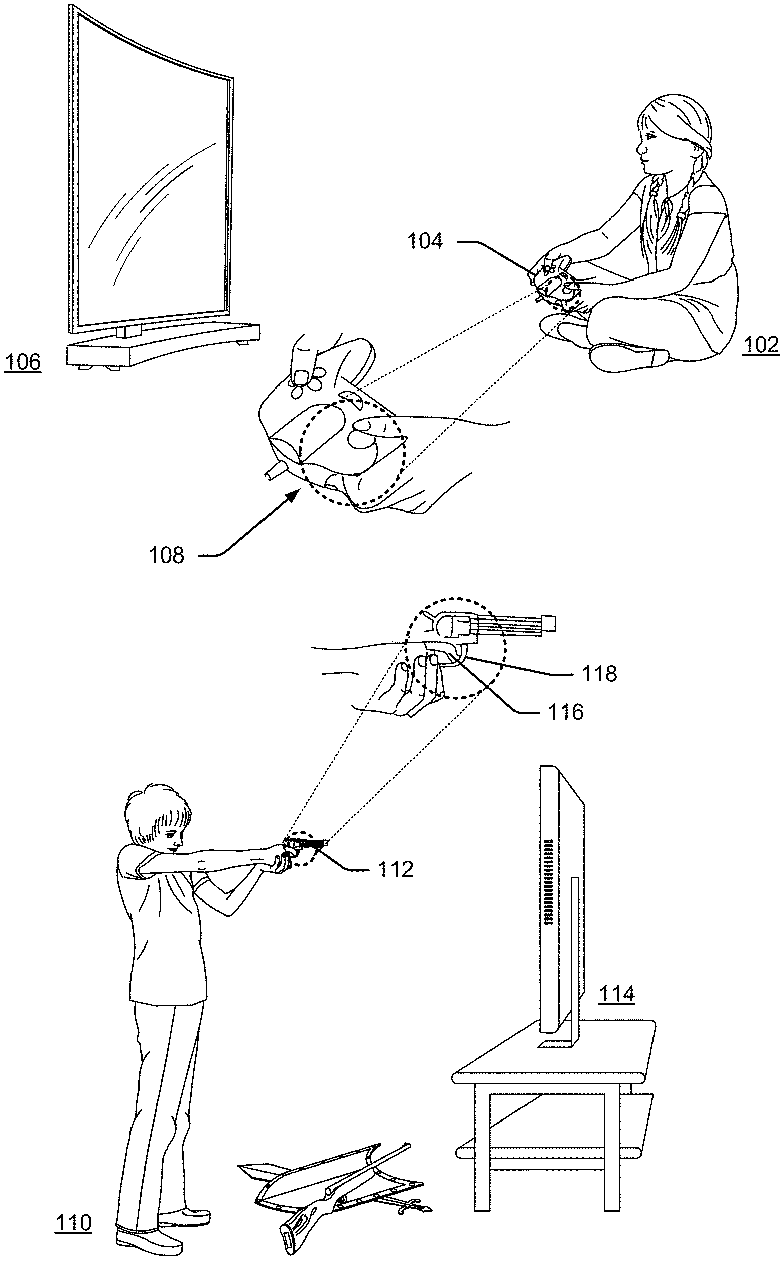
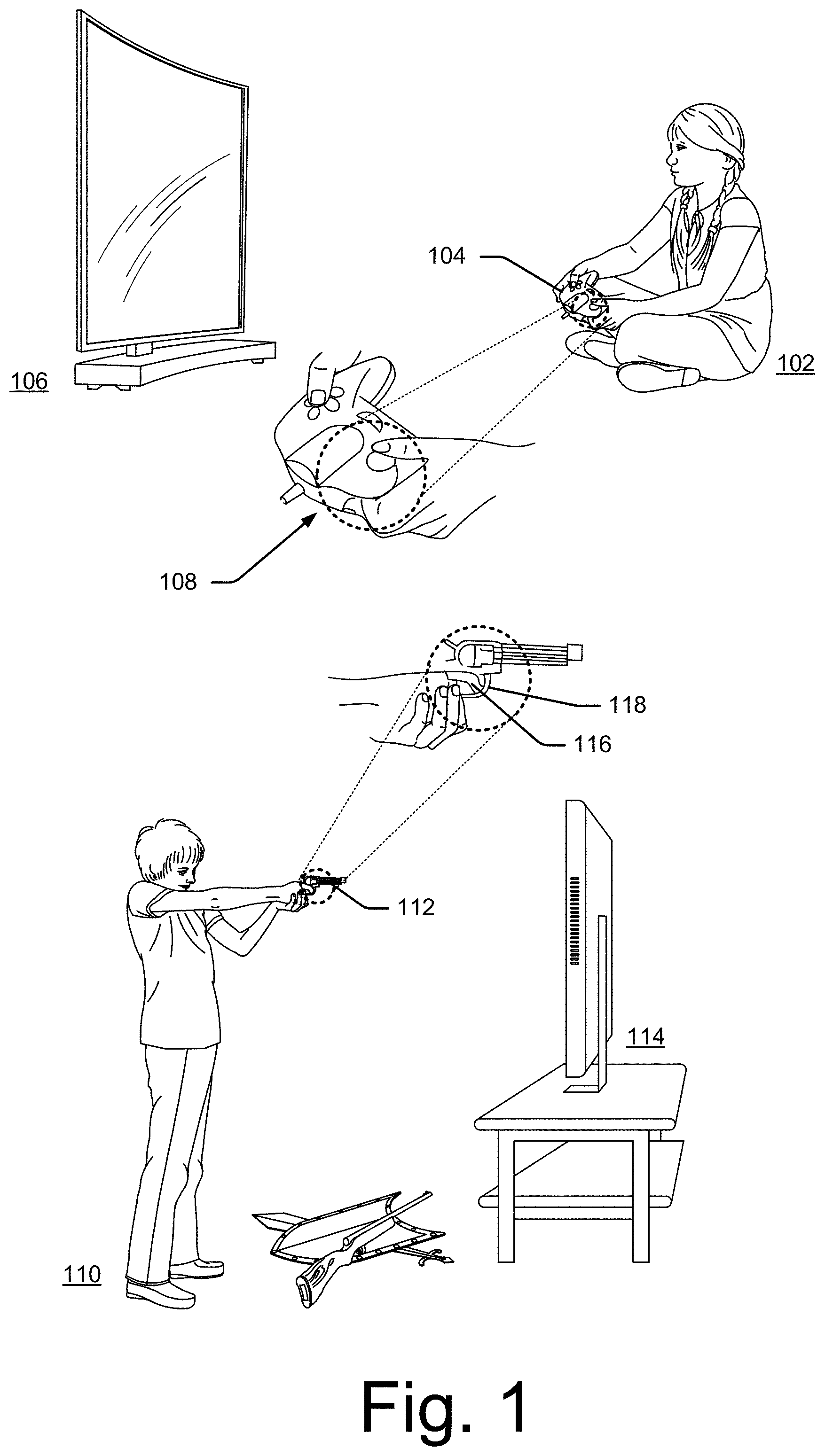
[0008] FIG. 1 illustrates two example cases in which advanced gaming and VR control using radar can be used, a user playing a video game using a mock controller and a user playing another game with a mock weapon;
[0009] FIG. 2 illustrates an example implementation of the computing devices of FIG. 1 in greater detail, including setting out a radar system and various modules enabling the techniques;
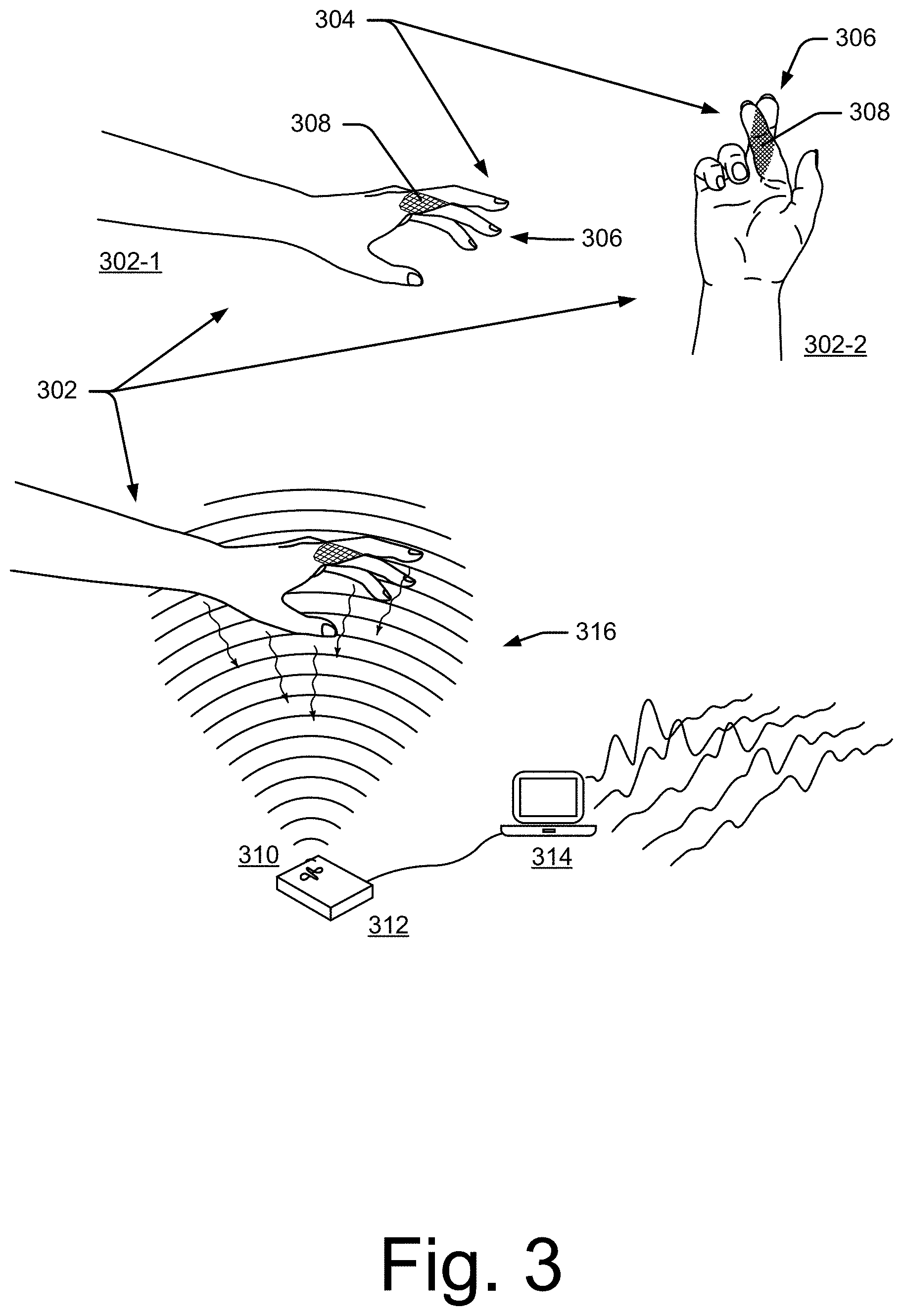
[0010] FIG. 3 illustrates a hand acting within a provided radar field, including an occluded portion of an index finger, as well as an example radar system and computing device;
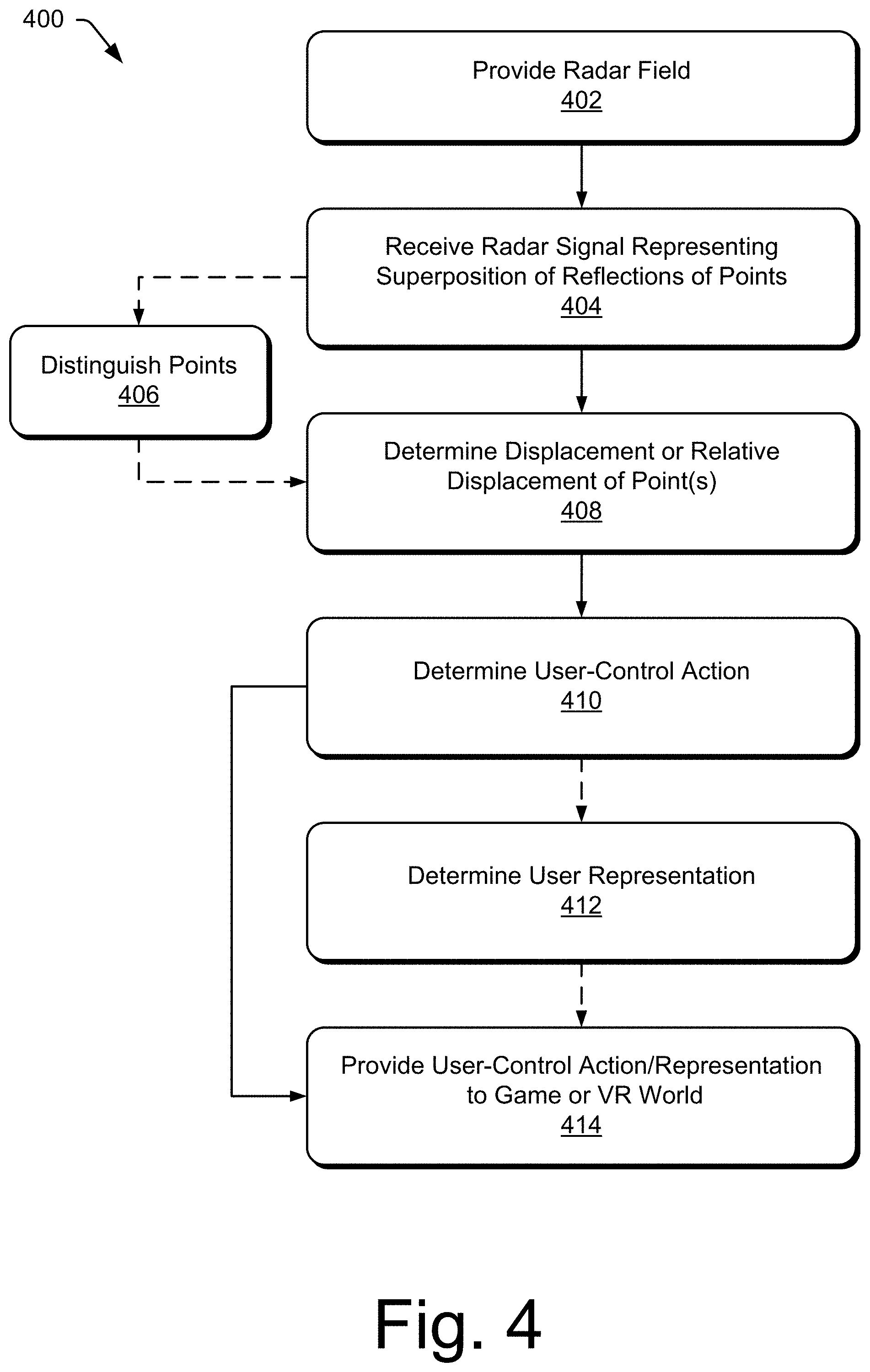
[0011] FIG. 4 illustrates an example method for advanced gaming and virtual reality control using radar;
[0012] FIG. 5 illustrates a simple example of RF source-wave propagation and a corresponding reflected-wave propagation;
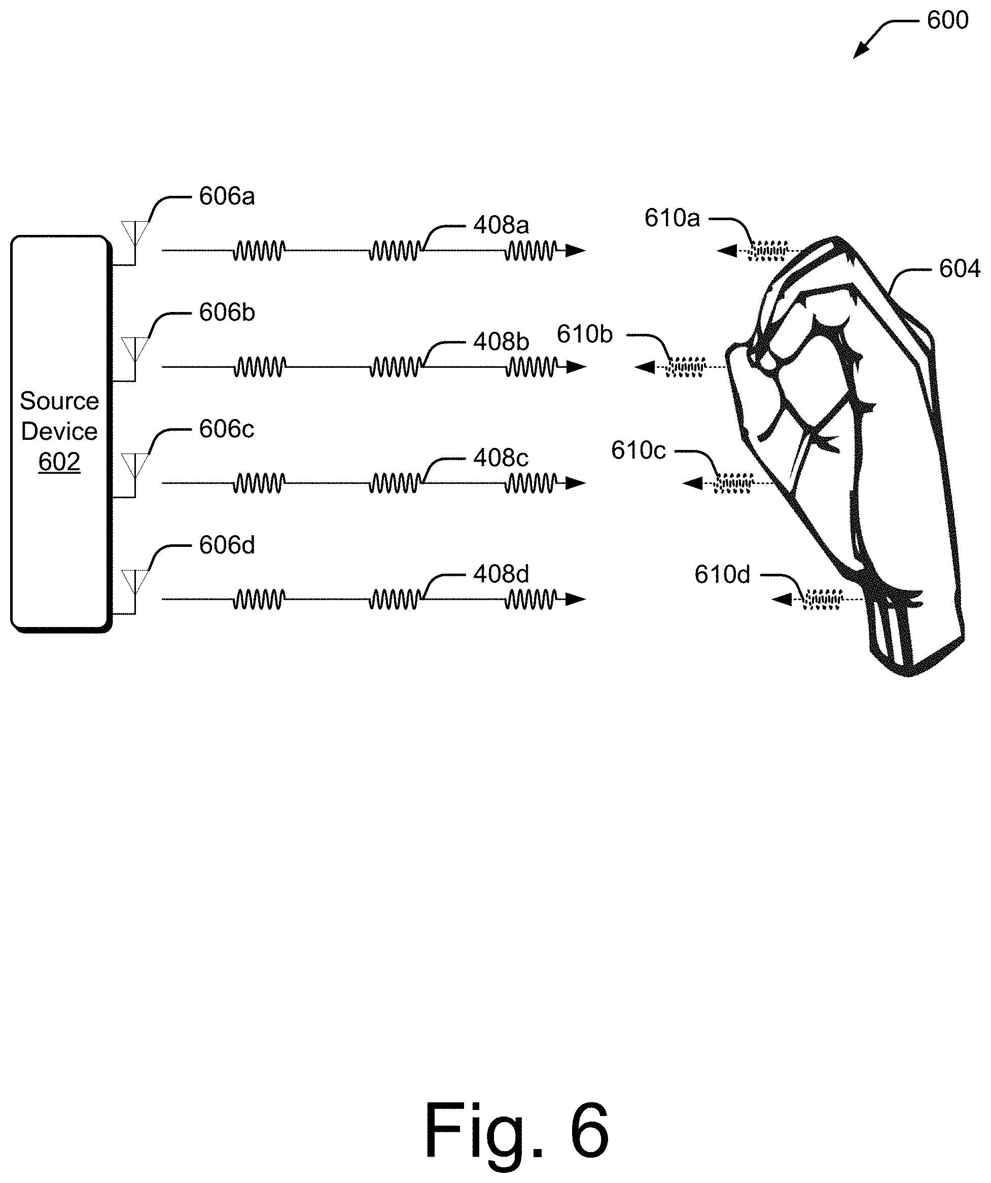
[0013] FIG. 6. illustrates an example environment in which multiple antenna are used to receive information about a target object;
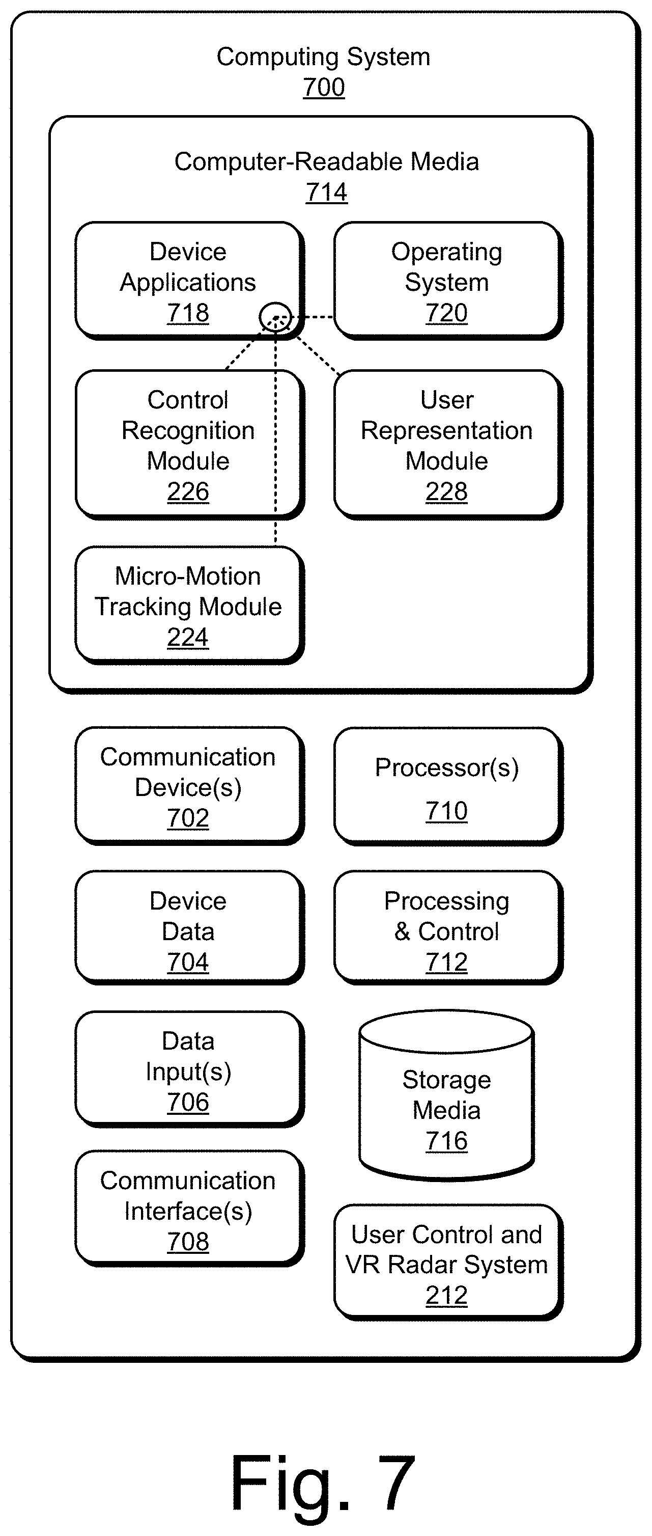
[0014] FIG. 7 illustrates an example computing system embodying, or in which techniques may be implemented that enable use of, advanced gaming and virtual reality control using radar.
DETAILED DESCRIPTION
[0015] Overview
[0016] Techniques are described herein that enable advanced gaming and virtual reality control using radar. These techniques enable small motions and displacements to be tracked, even in the millimeter or submillimeter scale, for user control actions even when those actions are optically occluded or obscured.
[0017] Consider, for example, a conventional optical or IR camera-enabled tracking system. This conventional system does not permit a user to use small motions or objects for control, such as just a fingertip, instead the user makes large body motions to control a game. And, for the VR world, a user represented by these conventional systems will not show finger orientation, finger movement, clothing movement or detail, as the resolution and these conventional optical or IR cameras is simply insufficient. Further still, any actions or parts of the person that are optically obscured from the camera will not be shown or shown correctly, which further limits this conventional technique.
[0018] Consider, as a second example, a conventional RF system for tracking motions and objects. The resolution of these conventional RF system is constrained by its antenna-beam width and bandwidth, both of which are based on the hardware of the conventional radar system. While somewhat better resolution can be obtained through multiple antennas, this increases complexity and cost while increasing lag-time between an action and that action being shown or its control made to the game or VR world. Even with a dozen antennas, the resolution is inferior to a single antenna using the disclosed advanced gaming and VR techniques.
[0019] In contrast to these inferior conventional techniques, consider techniques for advanced gaming and VR control using radar, which overcome hardware limitations of conventional radar systems and can recognize optically occluded or obscured motions. Consider two examples illustrated in FIG. 1. In the first, a user 102 is using a mock game controller 104 to play a video game on a computing device 106. This mock game controller 104 does not need any electronics, control capabilities, or communication capabilities by which to control the game. Further the mock game controller 104 can be obscured by being in a dark room or having shading where some part of the controller is well lit but others are dark, such as obscured portion 108. Note that in turning the mock controller 104 toward her left hand and down, that the obscured portion 108 is likely to be less-well lighted, as well as partially occluded from a radar field emitted from the computing device 106. Even so, the techniques permit the user 102 to play the game with fine motion, real-time control.
[0020] In the second example, a user 110 is using a mock weapon 112 to play a video game on computing device 114. Assume that this game is a "first person shooter" video game where the user 110 is fighting against a legion of zombies. Like many of these types of games, a player can see an oft-clumsy avatar approximation of his or her arms and feet, as well as the surrounding game world. The player can pick up supplies, tools, and weapons, which is one of the central parts of the game. In contrast to current techniques, these advanced techniques can permit the player to use and see his or her micro motions and small objects--such as a player's own arms, own hands, own feet (or an accurate representation) and their actual movements. In addition, note that the user's right index finger 116 is obscured by a trigger guard 118 of the mock weapon 112. Even so, the advanced techniques enable control through movement of the user's right index finger 116, obscured or otherwise.
[0021] The level of motion and orientation permitted by these advanced techniques can even permit the player to see his or her own self in the game world (or VR world in the case of a helmet or visor being worn), rather than a blockish avatar. Further, the player can now pick up actual mock tools and weapons and use them--even if those weapons or tools have no control capabilities. If, in the game world, a weapon is sitting on the ground, a player can pick up in the real world a plastic version of this weapon or even a toy from around the house, like a nerf gun, and use it in the game. The fine motions and ability to overcome occlusions can track the player's finger moving on the plastic trigger even when it is occluded by the weapon while also tracing movement of the weapon to aim at the zombie. All of this can be accurately and precisely shown in the VR world or game world, and enable control in the VR world or game. When the player picks up the plastic weapon, points it at the zombie, and pulls the trigger, the picking up, the pointing, and the fine motion of pulling the trigger, all can tracked by these advanced techniques.
[0022] This document now turns to an example computing device in which advanced gaming and virtual reality control using radar can be used, and then follows with an example computing device, an example radio field and occluded portion of a user's hand, a method, example RF wave propagations, and ends with an example computing system.
[0023] Example Computing Device
[0024] Having generally described example uses of advanced gaming and VR control user radar, now consider FIG. 2, which illustrates an example implementation of the computing devices of FIG. 1 in greater detail. Computing device 202 represents any suitable type of computing device in which various embodiments can be implemented. In this example, various devices include, by way of example and not limitation: smart glasses 202-1, smart watch 202-2, mobile phone 202-3, tablet 202-4, laptop 202-5, and desktop computer 202-6. It is to be appreciated that these are merely examples for illustrative purposes, and that any other suitable type of computing device can be utilized without departing from the scope of the claimed subject matter, such as a netbook, dedicated gaming console, a lighting system, or an audio system.
[0025] The computing device 202 includes one or more computer processors 204 and computer-readable media 206. Applications 208 and/or an operating system (not shown) embodied as computer-readable instructions on the computer-readable media 206 can be executed by the processors 204 to invoke or interface with some or all of the functionalities described herein, such as through user control and VR Application Programming Interfaces (APIs) 210. These applications 208 may include game applications or virtual reality programs, through other non-game and non-VR programs may instead by used, such as to control media, web browsing, and so forth.
[0026] The user control and VR APIs 210 (APIs 210) provide programming access into various routines and functionality incorporated into user control and VR radar system 212 (radar system 212). In some embodiments, the APIs 210 provide high-level access into the radar system 212 in order to abstract implementation details and/or hardware access from a calling program, request notifications related to identified events, query for results, and so forth. The APIs 210 can also provide low-level access to the radar system 212, where a calling program can control direct or partial hardware configuration of the radar system 212. In some cases, the APIs 210 provide programmatic access to input configuration parameters that configure transmit signals and/or select VR or user-control recognition algorithms. These APIs enable programs, such as the applications 208, to incorporate the functionality provided by the radar system 212 into executable code. For instance, the applications 208 can call or invoke APIs 210 to register for, or request, an event notification when a particular micro-motion user control has been detected, enable or disable wireless gesture recognition in the computing device 202, and so forth. At times, the APIs 210 can access and/or include low-level hardware drivers that interface with hardware implementations of the radar system 212. Alternately or additionally, the APIs 210 can be used to access various algorithms that reside on the radar system 212 to configure algorithms, extract additional information (such as 3D tracking information, angular extent, reflectivity profiles from different aspects, correlations between transforms/features from different channels), change an operating mode of the radar system 212, and so forth.
[0027] The radar system 212 is shown separate from the computer-readable media 206, though it may contain computer-readable instructions. Thus, the radar system 212 can be implemented in part as a chip embedded within the computing device 202, such as a System-on-Chip (SoC), one or more Integrated Circuits (ICs), as a processor with embedded processor instructions, or configured to access processor instructions stored in memory, as hardware with embedded firmware, a printed circuit board with various hardware components, or any combination thereof. Here, the radar system 212 includes a radar-emitting element 214, one or more antennas 216, a digital signal processor 218, a machine-learning component 220, and a user-control and VR library 222. In conjunction with micro-motion tracking module 224, control recognition module 226, and/or user representation module 228 (each described below), the radar system 212 can enable advanced gaming and virtual reality control, even for millimeter-scale and occluded or obscured movements.
[0028] Generally, the radar-emitting element 214 is configured to provide a radar field. The radar field is configured to at least partially reflect off a target object. The radar field can also be configured to penetrate fabric or other obstructions and reflect from human tissue, such as a gaming implement (e.g., a mock game controller, weapon, or tool). These fabrics or obstructions can include wood, glass, plastic, cotton, wool, nylon and similar fibers, and so forth, while reflecting from human tissues, such as a person's hand. The radar field may also reflect from objects, such as a part of a game controller, trigger on a mock weapon, or button on a mock tool to discern small motions, or even larger motions, such as movement of a tool or pointing of a mock weapon.
[0029] A radar field can be a small size, such as 1 millimeter to 10 centimeters, moderate, such as 10 centimeters to 1.5 meters, or moderately large, such as 0.5 to 8 meters (or larger). It is to be appreciated that these sizes are merely for discussion purposes, and that any other suitable range can be used. The radar system 212 and modules 224, 226, or 228 can receive and process reflections of the radar field to provide large-body gestures based on reflections from human tissue caused by body, arm, or leg movements, either alone or in conjunction with small motions. Multiple radar fields can be used, or one field that enables determination of both small and large movements as noted below. Example uses of both large and small motion and position detection include determining a position of a user in three dimensions and large movements for the user, such as arm, leg, or a larger object's position or movement. These, along with small movements, such as fingers and the like, can be combined for realistic VR representations of the user, or for combined user control actions, like both pointing a mock weapon and pulling the trigger.
[0030] The antennas 216 receive RF signals. These antennas 216 (or a single antenna) can receive various types of reflections, such as a radar signal representing a superposition of reflections of two or more points within the radar field provided by the radar-emitting element 214 of the radar system 212. Often, one of the first or second points will be optically occluded. This optical occlusion resides between the antenna 216 and the point that is optically occluded. Example occlusions include mock or real game controllers, mock tools or weapons, food, gloves, clothing, books, other electronic devices, and so forth. Furthermore, often one of these points will be visually obscured. A point on an object is visually obscured with the lighting of that point is dark or otherwise difficult to optically capture, such as when the point is dark relative to at least another of the two or more points or to an ambient lighting of objects within the radar field. Consider, for example, the user 102 of FIG. 1, and her mock game controller 104. If she is sitting in a dark room, which is often the case for game playing, or even in a well-lighted room, as she moves the controller and her hands, buttons of the controller or her fingers can easily have substantial lighting changes, including those that make them difficult to optically capture.
[0031] These antennas 216 can be configured as a dipole antenna, a parabolic antenna, a helical antenna, a monopole antenna, and so forth. In some embodiments, the antennas 216 are constructed on-chip (e.g., as part of an SoC), while in other embodiments, the antennas 216 are separate components, metal, hardware, etc. that attach to, or are included within, the radar system 212. The placement, size, and/or shape of the antennas 212 can be chosen to enhance a specific transmission pattern or diversity scheme, such as a pattern or scheme designed to capture information about a micro-gesture performed by the hand, as further described above and below.
[0032] The digital signal processor 218 generally represents digitally capturing and processing a signal. For instance, the digital signal processor 218 samples analog RF signals received by the antennas 216 to generate digital samples that represents the RF signals, and then processes these samples to extract information about the target object. Alternately or additionally, the digital signal processor 218 controls the configuration of signals generated and transmitted by the radar-emitting element 214 and/or antennas 216, such as configuring a plurality of signals to form a specific diversity scheme like a beamforming diversity scheme. In some cases, the digital signal processor 218 receives input configuration parameters that control an RF signal's transmission parameters (e.g., frequency channel, power level), such as through the APIs 210. In turn, the digital signal processor 218 modifies the RF signal based upon the input configuration parameter. At times, the signal processing functions of the digital signal processor 218 are included in a library of signal processing functions or algorithms that are also accessible and/or configurable via the APIs 210. The digital signal processor 218 can be implemented in hardware, software, firmware, or any combination thereof.
[0033] Among other things, the machine-learning component 220 receives information processed or extracted by the digital signal processor 218, and uses that information to classify or recognize various aspects of the target object. In some cases, the machine-learning component 220 applies one or more algorithms to probabilistically determine which gesture has occurred given an input signal and previously learned gesture features. As in the case of the digital signal processor 218, the machine-learning component 220 can include a library of multiple machine-learning algorithms, such as a Random Forrest algorithm, deep-learning algorithms (e.g., artificial neural network algorithms, convolutional neural net algorithms), clustering algorithms, Bayesian algorithms, and so forth. The machine-learning component 220 can be trained on how to identify various gestures using input data that consists of example gesture(s) to learn. In turn, the machine-learning component 220 uses the input data to learn what features can be attributed to a specific gesture. These features are then used to identify when the specific gesture occurs. In some embodiments, the APIs 210 can be used to configure the machine-learning component 220 and/or its corresponding algorithms.
[0034] The user control and VR library 222 represents data used by the digital signal processor 218, the machine-learning component 220, and/or modules of FIG. 2, to identify a target object and/or user control actions or movements performed by the target object. For instance, the user control and VR library 222 can store signal characteristics, or characteristics about a target object that are discernable from a signal, such as a particular mock tool, mock controller, and so forth. By so doing, these objects can be tracked and also differentiated from other signals, such as those of a person arm or hand.
[0035] In addition, certain data stored in user control and VR library 222 may be treated in one or more ways before it is stored or used, so that personally identifiable information is removed. For example, a user's identity may be treated so that no personally identifiable information can be determined for the user, or a user's geographic location may be generalized where location information is obtained (such as to a city, ZIP code, or state level), so that a particular location of a user cannot be determined. Thus, the user may have control over what information is collected about the user, how that information is used, and what information is provided to the user.
[0036] Generally, the micro-motion tracking module 224 is configured to determine displacement of a point, or a relative displacement between points, determined from a radar signal representing reflections of one or more points within the radar field. In the case of a single point, the micro-motion tracking module 224 is configured to differentiate the point from other points, and then, based on an energy and velocity of the part of the signal associated with the point, determine a velocity of the point. In the case of multiple points, the micro-motion tracking module 224 is configured to determine a relative displacement between a first and second point of the multiple points. At least one of these points is associated with a user--in some cases a point is associated by being part of the user and in others the point is of something touched by the user, such as a mock controller (a lever or button), weapon (a trigger), or tool. Also, even though at least one of these points is occluded or obscured, the micro-motion tracking module 224 is able to spatially resolve the first and second points to provide at least a relative velocity or displacement of the points relative to each other or some third point. As noted in part above, the resolving can be at a resolution finer than a wavelength of the radar field provided by the radar system. Thus, as the wavelength is a constrain of the hardware of the system, the techniques described herein overcome that hardware constraint.
[0037] In more detail, the micro-motion tacking module 224 may determine a relative displacement by measuring a radial distance for each of the first and second points using a time delay between transmittal of the radar field and receiving the radar signal, measuring a radial velocity through an observed Doppler frequency for each of the first and second points, and measuring a reflected energy for each of the first and second points. This may be performed instead or in conjunction by components of the radar system 212 as well. Assume, for example, that the radar signal includes two sets of data, each set of data from one of two radar emitter-antenna pairs. In such a case, measuring the radial velocity can be through a range-Doppler map for one of the first or second points, per set of data. Also, this relative displacement can be calculated over a time series effective to track the first and second points over multiple relative displacements over time.
[0038] The micro-motion tracking module 224 may also, prior to determining the displacement, distinguish the point or points. In some cases this is performed by tracking temporal changes in the radar signal. This distinguishing can be performed by determine a micro-Doppler centroid for each point of interest, respectively. Thus, distinguishing points can be based on one of the first or second point having a different characteristic to a signal associated with the one of the first or second points than another signal associated with another of the first or second points.
[0039] In the case of occlusions, the micro-motion tracking module 224 can distinguish points prior to one of the points being optically occluded by tracking the points over time and then determining that one of the points is optically occluded based on an alteration of a characteristic of a signal associated with the optically occluded point. With this alteration known, further distinguishing and tracking can be performed based on the altered characteristic of the signal associated the occluded point. And, when the point that is occluded ceases to be occluded this change to the signal can also be noted, and back and forth. Thus, a finger on a mock controller can be tracked prior to occlusion, then the finger is occluded by the controller and tracked as an occluded point based on the altered signal, and then when no longer occluded by the controller the finger is tracked with the alteration no longer preset.
[0040] Consider, for example, FIG. 3, which illustrates a user's hand 302 (shown in side view 302-1 and bottom view 302-2), an index finger 304, and a middle finger 306. Note that a portion of the index finger 304, occluded portion 308, is occluded relative to antenna 310 of radar system 312, shown as a peripheral of a computing device 314. The techniques, here through the micro-motion tracking module 224 of FIG. 2, can track even the occluded portion 308 of the index finger 304. Other aspects of FIG. 3 are described in the context of methods discussed below.
[0041] Returning to FIG. 2, generally, the control recognition module 226 is configured to determine a user control action based on the displacement of a point tracked by the micro-motion tracking module 224, or based on the relative displacement between two or more points also tracked by the micro-motion tracking module 224. This control action can be one on many different types and sizes of control actions, from fine motion, millimeter-scale control of a level or button or wheel on a mock game controller, a partially-occluded in-the-air gesture of a hand and fingers, a user pulling a trigger of a mock weapon, or larger-scale control, such as picking up a shield and moving it to block a game-opponent's sword strike, aiming a weapon at a zombie, or even jumping up to avoid a VR or game-world snare. The control recognition module 226 may recognize movements that are previously cataloged or simply determine the motion and pass the motion in a format usable by one of the applications 208 through the APIs 210. A movement of a trigger or putting a shield up to deflect a blow need not be cataloged or previously known gesture or action. Some actions and movements, however, are known and, in such cases, the user control and VR library 222 is used to determine the particular command or action desired by the movement. Thus, the user control need not be a particular gesture, but may instead by a movement, e.g., that the user 102 has pressed lever A forward 1/4 or that the user 108 has moved the mock weapon 110 some number of degrees in a direction and then moved his index finger (pulling the trigger) some distance.
[0042] Generally, the user representation module 228 is configured to determine a user's representation based on a displacement or relative displacement of points associated with the user, which may include data that is solely in the millimeter scale but may also include data that is of a larger scale, whether provided by the radar system or other sensing system. Thus, the user representation module 228 may determine fine motions based on displacement or motion from the micro-motion tracking module 224, but may also, from the radar system or even an optical or IR camera, receiving data indicating a user's stance, position, or large motions.
[0043] In more detail, the user representation module 228 is configured to determine a location in three dimensions, or relative to a user, for one or more points based on a displacement or relative displacement between points. Data indicating a position of the user may also be used. Thus, assume that the user representation module 228 knows a user's general body location of feet, legs, arms, and centroid of a hand (but not detail of the hand) Based on this, the user representation module 228 may place the fingers for the hand based on the fine displacement from the radar system, and well as their fine, real-time movement for the hand With this, the game or VR world is given sufficient information to accurately place the user and the user's fine motions in the game or VR world.
[0044] The computing device 202 may also include one or more network interfaces 230 for communicating data over wired, wireless, or optical networks and a display 232. The network interface 230 may communicate data over a local-area-network (LAN), a wireless local-area-network (WLAN), a personal-area-network (PAN), a wide-area-network (WAN), an intranet, the Internet, a peer-to-peer network, point-to-point network, a mesh network, and the like. The display 232 can be integral with the computing device 202 or associated with it, such as with the desktop computer 202-6.
[0045] Having described the computing device 202 in accordance with one or more embodiments, now consider example methods for advanced gaming and VR control using radar.
[0046] Example Method
[0047] FIG. 4 depicts a method 400 for advanced gaming and virtual reality control using radar. The method 400 receives a radar signal from a radar system in which a hand, object, or person's body makes a movement, determines a displacement at a finer resolution than conventional techniques permit based on the parameters of the radar system, and then, based on this displacement, determines user control actions or a user's representation, even in a millimeter or submillimeter scale. This method is shown as sets of blocks that specify operations performed but are not necessarily limited to the order or combinations shown for performing the operations by the respective blocks. In portions of the following discussion reference may be made to FIGS. 1-3 and 5-7, reference to which is made for example only. The techniques are not limited to performance by one entity or multiple entities operating on one device, or those described in these figures.
[0048] At 402, a radar field is provided, such as shown in FIG. 3 at radar field 316. The radar field can be provided by a simple radar system, including existing WiFi radar, and need not use complex, multi-emitter or multi-antenna, or narrow-beam scanning radars. Instead, a broad beam, full contiguous radar field can be used, such as 57-64 or 59-61 GHz, though other frequency bands, even sounds waves, can be used.
[0049] At 404, a radar signal representing a superposition of reflections of points within the radar field are received. As noted, at least one of the points can be optically occluded or obscured. In the case of an optical occlusion, an object resides between a radar antenna of the radar system and the point that is optically occluded. An example of this is shown in FIG. 3 at the occluded portion 308 of the index finger 304.
[0050] At 406, optionally and prior to block 408, two or more points are distinguished by tracking temporal changes in the radar signal. As noted above, this can be done by the micro-motion tracking module 224 by determining micro-Doppler centroids for the points.
[0051] At 408, a relative displacement between a point or multiple of the points is determined by spatially resolving the points. Note that a single displacement can be determined by the techniques, though very fine displacements can be determined more accurately or with fewer computing resources when the relative displacement between two points is determined.
[0052] At 410, a user control action is determined based on the displacement or relative displacement of the point or first and second points. Note that this can simply be provided effective to enable determination of the user control action. This is described in detail above. Also as noted in part above, a movement common to two points can be determined and this movement or displacement passed--this can aid in determining movement of a gaming implement. Thus, the techniques may determine, based on a movement of a centroid of the combination of the points, a movement of a game implement. If the techniques track a front of a mock weapon and track a user's finger the mock weapon, the common movement tracks the mock weapon, such as to point it at a particular spot on the displace of the computing device. The techniques can also determine a position of a user or larger objects, like an arm, leg, or tool. This position can be used with the fine motions to provide additional control or a more accurate representation of the user in the game or VR world.
[0053] At 412, optionally a representation of the user is determined, such as by the user representation module 228 described above. In such a case, a displacement of a point in three dimensions or relative to a user is determined.
[0054] At 414, the user control action and/or user representation is provided, such as to a game or VR application. In the case of the user control action, the relative or absolute displacement or velocity can be passed sufficient to enable the user's movement of him or herself, or a tool or object associated with him or her, to be passed to an application. In the case of a user representation, a position, e.g., in three dimension, or relative to the user is passed to a game or VR program to represent, in a game user interface or a virtual reality world, respectively, points associated with the user.
[0055] Through operations of method 400 and as noted above, relative dynamics are extracted from the radar signal representing the superposition of the reflections of multiple points within the radar field. These relative dynamics indicate a displacement of points relative one to another, from which micro-motions and larger movements can be determined. As noted above, in some cases extracting relative dynamics from the superposition determines micro-Doppler centroids for the points. These micro-Doppler centroids enable computationally light super-resolution velocity estimates to be determined. Thus, the computational resources needed are relatively low compared to conventional radar techniques, further enabling use of these RF-based micro-motion techniques in small or resource-limited devices, such as some wearable devices and appliances. Not only can these techniques be used on resource-limited devices, but the computationally light determination can permit faster response to a user action, such as in real time as a small, fine motion to move a dummy physical controller or maneuver a tool.
[0056] Further, the RF-based micro-motion techniques, by using micro-Doppler centroids, permits greater robustness to noise and clutter than use of Doppler profile peaks. To increase resolution, the micro-motion tracking module 224 may use the phase change of the radar signal to extract millimeter and sub-millimeter displacements for high-frequency movements of the points.
[0057] Example RF Signal Propagation in Radar-Based Gesture Devices
[0058] Having discussed example apparatuses and methods for advanced gaming and virtual reality control using radar, the discussion now turns to example manners in which RF radar can be used. Consider FIG. 5, which illustrates a simple example of RF source-wave propagation, and a corresponding reflected-wave propagation. The following discussion has been simplified, and is not intended to describe all technical aspects of RF source-wave propagation, reflected-wave propagation, or user-control action and micro-motion determination and detection techniques.
[0059] Environment 500 includes a source device 502 and an object 504. The source device 502 includes an emitter/receive antenna 506, which generally represents functionality configured to transmit and receive electromagnetic waves in the form of an RF signal. The emitter/receiver antenna 506 can be coupled to a source, such as a radar-emitting element (e.g., the radar-emitting element 214), to achieve transmission of a signal. In this example, the source device 502 transmits a series of RF pulses, illustrated here as the RF pulse 508-1, the RF pulse 508-2, and the RF pulse 508-3. As indicated by their ordering and distance from the source device 502, the RF pulse 508-3 is transmitted first in time, followed by the RF pulse 508-2, and then the RF pulse 508-1. For discussion purposes, these RF pulses have the same pulse width, power level, and transmission periodicity between pulses, but another suitable type of signal with alternate configurations can be transmitted without departing from the scope of the claimed subject matter.
[0060] Generally speaking, electromagnetic waves can be characterized by the frequency or wavelength of their corresponding oscillations. Being a form of electromagnetic radiation, RF signals adhere to various wave and particle properties, such as reflection. When an RF signal reaches an object, it will undergo some form of transition. Specifically, there will be some reflection off the object. The environment 500 also illustrates the reflection of RF pulses 508-1, 2, and 3 reflecting off of the object 504, where an RF pulse 510-1 corresponds to a reflection originating from the RF pulse 508-1 reflecting off of the object 504, the RF pulse 510-2 corresponds to a reflection originating from the RF pulse 508-2, and so forth. In this simple case, the source device 502 and the object 504 are stationary, and the RF pulses 508-1, 2, and 3 are transmitted via a single antenna (the antenna 506) over a same RF channel, and are transmitted directly towards the object 504 with a perpendicular impact angle. Similarly, the RF pulses 5101, 2, and 3 are shown as reflecting directly back to the source device 502, rather than with some angular deviation. However, as one skilled in the art will appreciate, these signals can alternately be transmitted or reflected with variations in their transmission and reflection directions based upon the configuration of the source device 502, the object 504, transmission parameters, variations in real-world factors, and so forth. Upon receiving and capturing the RF pulses 5101, 2, and 3, the source device 502 can then analyze the pulses, either individually or in combination, to identify characteristics related to the object 504. For example, the source device 502 can analyze all of the received RF pulses to obtain temporal information and/or spatial information about the object 504. Accordingly, the source device 502 can use knowledge about a transmission signal's configuration (such as pulse widths, spacing between pulses, pulse power levels, phase relationships, and so forth), and further analyze a reflected RF pulse to identify various characteristics about the object 504, such as size, shape, movement speed, movement direction, surface smoothness, material composition, and so forth.
[0061] Now consider FIG. 6, which builds upon the above discussion of FIG. 5. FIG. 6 illustrates example environment 600 in which multiple antenna are used to ascertain information about a target object. The environment 600 includes the source device 602 and a target object, shown here as hand 604. Generally speaking, the source device 602 includes antennas 606 to transmit and receive multiple RF signals. In some embodiments, the source device 602 includes the radar system 212 and modules of FIG. 2. The antennas 606 correspond to the antennas 216. While the source device 602 in this example includes four antennas, it is to be appreciated that any suitable number of antennas can be used. Each antenna of the antennas 606 is used by the source device 602 to transmit a respective RF signal (e.g., antenna 606-1 transmits RF signal 608-1, antenna 606-2 transmits RF signal 608-2, and so forth). As discussed above, these RF signals can be configured to form a specific transmission pattern or diversity scheme when transmitted together. For example, the configuration of the RF signals 608, as well as the placement of the antennas 606 relative to a target object, can be based upon beamforming techniques to produce constructive interference or destructive interference patterns, or alternately configured to support triangulation techniques. At times, the source device 602 configures the RF signals 608 based upon an expected information extraction algorithm, as further described below.
[0062] When the RF signals 608 reach the hand 604, they generate reflected RF signals 610. Similar to the discussion of FIG. 5 above, the source device 602 captures these reflected RF signals, and then analyzes them to identify various properties or characteristics of the hand 604, such as a millimeter-scale movement. For instance, in this example, the RF signals 608 are illustrated with the bursts of the respective signals being transmitted synchronously in time. In turn, and based upon the shape and positioning of the hand 604, the reflected signals 610 return to the source device 602 at different points in time (e.g., the reflected signal 610-2 is received first, followed by the reflected signal 610-3, then the reflected signal 610-1, and then the reflected signal 610-4). The reflected signals 610 can be received by the source device 602 in any suitable manner. For example, the antennas 606 can each receive all of the reflected signals 610, or receive varying subset combinations of the reflected signals 610 (e.g., the antenna 606-1 receives the reflected signal 610-1 and the reflected signal 610-4, the antenna 606-2 receives the reflected signal 610-1, the reflected signal 610-2, and the reflected signal 610-3, etc.). Thus, each antenna can receive reflected signals generated by transmissions from another antenna. By analyzing the various return times of each reflected signal, the source device 602 can determine shape and corresponding distance information associated with the hand 604. When reflected pulses are analyzed over time, the source device 602 can additionally discern movement. Thus, by analyzing various properties of the reflected signals, as well as the transmitted signals, various information about the hand 604 can be extracted, as further described below. It is to be appreciated that the above example has been simplified for discussion purposes and is not intended to be limiting.
[0063] As in the case of FIG. 5, FIG. 6 illustrates the RF signals 608 as propagating at a 90.degree. angle from the source device 602 and in phase with one another. Similarly, the reflected signals 610 each propagate back at a 90.degree. angle from the hand 604 and, as in the case of the RF signals 608, are in phase with one another. However, as one skilled in the art will appreciate, more-complex transmission signal configurations, and signal analysis on the reflected signals, can be utilized, examples of which are provided above and below. In some embodiments, the RF signals 608 can each be configured with different directional transmission angles, signal phases, power levels, modulation schemes, RF transmission channels, and so forth. These differences result in variations between the reflected signals 610. In turn, these variations each provide different perspectives of the target object which can be combined using data fusion techniques to yield a better estimate of the hand 604, how it is moving, its three-dimensional (3D) spatial profile, a corresponding user control action, and so forth.
[0064] Example Computing System
[0065] FIG. 7 illustrates various components of an example computing system 700 that can be implemented as any type of client, server, and/or computing device as described with reference to the previous FIGS. 1-6 to implement advanced gaming and virtual reality control using radar.
[0066] The computing system 700 includes communication devices 702 that enable wired and/or wireless communication of device data 704 (e.g., received data, data that is being received, data scheduled for broadcast, data packets of the data, etc.). Device data 704 or other device content can include configuration settings of the device, media content stored on the device, and/or information associated with a user of the device (e.g., an identity of an actor performing an action). Media content stored on the computing system 700 can include any type of audio, video, and/or image data. The computing system 700 includes one or more data inputs 706 via which any type of data, media content, and/or inputs can be received, such as human utterances, interactions with a radar field, user-selectable inputs (explicit or implicit), messages, music, television media content, recorded video content, and any other type of audio, video, and/or image data received from any content and/or data source.
[0067] The computing system 700 also includes communication interfaces 708, which can be implemented as any one or more of a serial and/or parallel interface, a wireless interface, any type of network interface, a modem, and as any other type of communication interface. Communication interfaces 708 provide a connection and/or communication links between the computing system 700 and a communication network by which other electronic, computing, and communication devices communicate data with the computing system 700.
[0068] The computing system 700 includes one or more processors 710 (e.g., any of microprocessors, controllers, and the like), which process various computer-executable instructions to control the operation of the computing system 700 and to enable techniques for, or in which can be embodied, advanced gaming and virtual reality control using radar. Alternatively or in addition, the computing system 700 can be implemented with any one or combination of hardware, firmware, or fixed logic circuitry that is implemented in connection with processing and control circuits, which are generally identified at 712. Although not shown, the computing system 700 can include a system bus or data transfer system that couples the various components within the device. A system bus can include any one or combination of different bus structures, such as a memory bus or memory controller, a peripheral bus, a universal serial bus, and/or a processor or local bus that utilizes any of a variety of bus architectures.
[0069] The computing system 700 also includes computer-readable media 714, such as one or more memory devices that enable persistent and/or non-transitory data storage (in contrast to mere signal transmission), examples of which include random access memory (RAM), non-volatile memory (e.g., any one or more of a read-only memory (ROM), flash memory, EPROM, EEPROM), and a disk storage device. A disk storage device may be implemented as any type of magnetic or optical storage device, such as a hard disk drive, a recordable and/or rewriteable compact disc (CD), any type of a digital versatile disc (DVD), and the like. The computing system 700 can also include a mass storage media device (storage media) 716 and the user control and VR radar system 212 and its various components.
[0070] The computer-readable media 714 provides data storage mechanisms to store the device data 704, as well as various device applications 718 and any other types of information and/or data related to operational aspects of the computing system 700. For example, an operating system 720 can be maintained as a computer application with the computer-readable media 714 and executed on the processors 710. The device applications 718 may include a device manager, such as any form of a control application, software application, signal-processing and control module, code that is native to a particular device, an abstraction module or gesture module and so on. The device applications 718 also include system components, engines, or managers to implement advanced gaming and virtual reality control using radar, such as the micro-motion tracking module 224, the control-recognition module 226, and the user representation module 228.
[0071] The computing system 700 may also include, or have access to, one or more of radar systems, such as the radar system 212 having the radar-emitting element 214 and the antenna element 216. While not shown, one or more components of the micro-motion tracking module 224, the control recognition module 226, or the user representation module 228 may be operated, in whole or in part, through hardware or firmware.
CONCLUSION
[0072] Although techniques using, and apparatuses including, advanced gaming and virtual reality control using radar have been described in language specific to features and/or methods, it is to be understood that the subject of the appended claims is not necessarily limited to the specific features or methods described. Rather, the specific features and methods are disclosed as example implementations of ways in which to determine advanced gaming and virtual reality control using radar.
* * * * *
D00000
D00001
D00002
D00003
D00004
D00005
D00006
D00007
XML
uspto.report is an independent third-party trademark research tool that is not affiliated, endorsed, or sponsored by the United States Patent and Trademark Office (USPTO) or any other governmental organization. The information provided by uspto.report is based on publicly available data at the time of writing and is intended for informational purposes only.
While we strive to provide accurate and up-to-date information, we do not guarantee the accuracy, completeness, reliability, or suitability of the information displayed on this site. The use of this site is at your own risk. Any reliance you place on such information is therefore strictly at your own risk.
All official trademark data, including owner information, should be verified by visiting the official USPTO website at www.uspto.gov. This site is not intended to replace professional legal advice and should not be used as a substitute for consulting with a legal professional who is knowledgeable about trademark law.