Lens Assembly
Wu; Guo-Yang ; et al.
U.S. patent application number 17/004255 was filed with the patent office on 2021-04-01 for lens assembly. The applicant listed for this patent is Asia Optical Co., Inc., Sintai Optical (Shenzhen) Co., Ltd.. Invention is credited to Hsi-Ling Chang, Bo-Yan Chen, Chien-Hung Chen, Guo-Yang Wu, Chun-Yang Yao.
| Application Number | 20210096325 17/004255 |
| Document ID | / |
| Family ID | 1000005064534 |
| Filed Date | 2021-04-01 |


View All Diagrams
| United States Patent Application | 20210096325 |
| Kind Code | A1 |
| Wu; Guo-Yang ; et al. | April 1, 2021 |
Lens Assembly
Abstract
A lens assembly includes a first lens, a second lens, a third lens, and a fourth lens. The first lens is with positive refractive power and includes a concave surface facing an object side and a convex surface facing an image side. The second lens is with negative refractive power and includes a concave surface facing the object side. The third lens is with positive refractive power. The fourth lens is with refractive power and includes a concave surface facing the image side. The first lens, the second lens, the third lens, and the fourth lens are arranged in order from the object side to the image side along an optical axis. The lens assembly satisfies: TTL/f>1.2; wherein TTL is a total length of optical system of the lens assembly and f is an effective focal length of the lens assembly.
| Inventors: | Wu; Guo-Yang; (Taichung, TW) ; Chen; Bo-Yan; (Taichung, TW) ; Chang; Hsi-Ling; (Taichung, TW) ; Yao; Chun-Yang; (Taichung, TW) ; Chen; Chien-Hung; (Taichung, TW) | ||||||||||
| Applicant: |
|
||||||||||
|---|---|---|---|---|---|---|---|---|---|---|---|
| Family ID: | 1000005064534 | ||||||||||
| Appl. No.: | 17/004255 | ||||||||||
| Filed: | August 27, 2020 |
| Current U.S. Class: | 1/1 |
| Current CPC Class: | G02B 13/0065 20130101; G02B 9/62 20130101; G02B 13/0045 20130101 |
| International Class: | G02B 9/62 20060101 G02B009/62; G02B 13/00 20060101 G02B013/00 |
Foreign Application Data
| Date | Code | Application Number |
|---|---|---|
| Sep 27, 2019 | CN | 201910923848.4 |
| Oct 31, 2019 | TW | 108139552 |
| Mar 5, 2020 | TW | 109107271 |
Claims
1. A lens assembly comprising: a first lens which is with positive refractive power and comprises a concave surface facing an object side and a convex surface facing an image side; a second lens which is with negative refractive power and comprises a concave surface facing the object side; a third lens which is with positive refractive power; and a fourth lens which is with refractive power and comprises a concave surface facing the image side; wherein the first lens, the second lens, the third lens, and the fourth lens are arranged in order from the object side to the image side along an optical axis; wherein the lens assembly satisfies: TTL/f>1.2; wherein TTL is a total length of optical system of the lens assembly and f is an effective focal length of the lens assembly.
2. The lens assembly as claimed in claim 1, wherein: the lens assembly further comprises a reflective element disposed between the first lens and the fourth lens; and the reflective element comprises a reflective surface.
3. The lens assembly as claimed in claim 1, wherein the second lens further comprises a convex surface or a concave surface facing the image side, the third lens comprises a convex surface facing the object side.
4. The lens assembly as claimed in claim 3, wherein: the third lens further comprises a concave surface or another convex surface facing the image side; and the fourth lens is with negative refractive power and further comprises a convex surface facing the object side.
5. The lens assembly as claimed in claim 3 further comprising a fifth lens disposed between the object side and the first lens, wherein: the fifth lens is a meniscus lens with positive refractive power and comprises a convex surface facing the object side and a concave surface facing the image side; the third lens further comprises a plane surface or another convex surface facing the image side; and the fourth lens is with negative refractive power and further comprises a plane surface or a convex surface facing the object side.
6. The lens assembly as claimed in claim 12 further comprising a fifth lens disposed between the fourth lens and the image side or the third lens and the fourth lens, wherein the fifth lens is with positive refractive power and comprises a convex surface facing the image side.
7. The lens assembly as claimed in claim 6 wherein the fifth lens further comprises another convex surface facing the object side; the second lens further comprises a convex surface or a concave surface facing the image side; the third lens comprises a convex surface facing the object side and a concave surface or a convex surface facing the image side; and the fourth lens is with positive or negative refractive power and further comprises a convex surface facing the object side.
8. The lens assembly as claimed in claim 6 further comprising a sixth lens disposed between the third lens and the fifth lens, wherein: the sixth lens is a meniscus lens with negative refractive power and comprises a concave surface facing the object side and a convex surface facing the image side; the fifth lens is a meniscus lens and further comprises a concave surface facing the object side; the second lens further comprises another concave surface facing the image side; the third lens further comprises another convex surface facing the image side; and the fourth lens is with positive refractive power and further comprises a convex surface facing the object side.
9. The lens assembly as claimed in claim 2, wherein the lens assembly satisfies at least any one of the following conditions: 5 mm<ALOD<14 mm; 0<TTL/ALOD<2; 1<(TTL+f)/f.sub.obj1<5; 1<f.sub.obj1/L1T<4; 0.2 mm.sup.2<L1T.times.L1SD<2.2 mm.sup.2; -4 mm.sup.2<L1T.times.R.sub.11<0 mm.sup.2; wherein ALOD is a total effective optical diameter of an object side surface of each lens of the lens assembly, TTL is a total length of optical system of the lens assembly, f is an effective focal length of the lens assembly, f.sub.obj1 is an effective focal length of a lens closest to the object side, L1T is a thickness along the optical axis of the first lens, L1SD is an effective optical semi-diameter of an image side surface of the first lens, and R.sub.11 is a radius of curvature of an object side surface of the first lens.
10. The lens assembly as claimed in claim 2, wherein the lens assembly satisfies at least any one of the following conditions: 0.5<M1T/L1T<4; 1<TTL/L<5; 0<L/f<2.5; -1<f.sub.obj3/f.sub.obj4<4; wherein M1T is an interval from an image side surface of the first lens to the reflective surface along the optical axis, L1T is a thickness along the optical axis of the first lens, TTL is a total length of optical system of the lens assembly, L is an interval from an object side surface of a lens closest to the object side to the reflective surface along the optical axis, f.sub.obj3 is an effective focal length of a lens third close to the object side, f.sub.obj4 is an effective focal length of a lens fourth close to the object side, and f is an effective focal length of the lens assembly.
11. The lens assembly as claimed in claim 6, wherein the lens assembly satisfies: -2 mm<8.times.M1T-(OD.sub.2+OD.sub.3+OD.sub.4+OD.sub.5)<1 mm; wherein M1T is an interval from an image side surface of the first lens to the reflective surface along the optical axis, OD.sub.2 is an effective optical diameter of an object side surface of a lens second close to the object side, OD.sub.3 is an effective optical diameter of an object side surface of a lens third close to the object side, OD.sub.4 is an effective optical diameter of an object side surface of a lens fourth close to the object side, and OD.sub.5 is an effective optical diameter of an object side surface of a lens fifth close to the object side.
12. A lens assembly comprising: a first lens which is with positive refractive power and comprises a convex surface facing an image side; a second lens which is with negative refractive power and comprises a concave surface facing an object side; a third lens which is with positive refractive power; a fourth lens which is with refractive power and comprises a concave surface facing the image side; and a reflective element which comprises a reflective surface; wherein the first lens, the second lens, the third lens, and the fourth lens are arranged in order from the object side to the image side along an optical axis; wherein the reflective element is disposed between the first lens and the fourth lens; wherein the lens assembly satisfies: 2 mm<L<6 mm; wherein L is an interval from an object side surface of a lens closest to the object side to the reflective surface along the optical axis.
13. The lens assembly as claimed in claim 12, wherein: the second lens further comprises a convex surface or a concave surface facing the image side; and the third lens comprises a convex surface facing the object side.
14. The lens assembly as claimed in claim 13, wherein the first lens further comprises another convex surface facing the object side.
15. The lens assembly as claimed in claim 12, wherein the lens assembly satisfies at least any one of the following conditions: 5 mm<ALOD<14 mm; 0<TTL/ALOD<2; wherein ALOD is a total effective optical diameter of an object side surface of each lens of the lens assembly and TTL is a total length of optical system of the lens assembly.
16. The lens assembly as claimed in claim 12, wherein the lens assembly satisfies at least any one of the following conditions: 1<(TTL+f)/f.sub.obj1<5; -1<f.sub.obj3/f.sub.obj4<2; 1<f.sub.obj3/L1T<4; 0.2 mm.sup.2<L1T.times.L1SD<2.2 mm.sup.2; -4 mm.sup.2<L1T.times.R.sub.11<0 mm.sup.2; 0.5<M1T/L1T<4; 1<TTL/L<5; 0<L/f<2.5; wherein TTL is a total length of optical system of the lens assembly, f is an effective focal length of the lens assembly, f.sub.obj1 is an effective focal length of a lens closest to the object side, f.sub.obj3 is an effective focal length of a lens third close to the object side, f.sub.obj4 is an effective focal length of a lens fourth close to the object side, L1T is a thickness along the optical axis of the first lens, L1SD is an effective optical semi-diameter of an image side surface of the first lens, R.sub.11 is a radius of curvature of an object side surface of the first lens, M1T is an interval from an image side surface of the first lens to the reflective surface along the optical axis, L1T is a thickness along the optical axis of the first lens, L is an interval from an object side surface of a lens closest to the object side to the reflective surface along the optical axis, and f is an effective focal length of the lens assembly.
17. The lens assembly as claimed in claim 1 further comprising a fifth lens disposed between the object side and the first lens, wherein: the fifth lens is a meniscus lens with positive refractive power and comprises a convex surface facing the object side and a concave surface facing the image side; the second lens further comprises a convex surface facing the image side; the third lens comprises a convex surface facing the image side; and the fourth lens is with negative refractive power and further comprises a convex surface facing the object side.
18. The lens assembly as claimed in claim 17, wherein the lens assembly satisfies: 8 mm.ltoreq.TTL1.ltoreq.9 mm; wherein TTL1 is an interval from the convex surface of the fifth lens to an image plane along the optical axis.
19. The lens assembly as claimed in claim 18, wherein the lens assembly satisfies: D=f/2, 2.85 mm.ltoreq.D.ltoreq.2.95 mm; wherein D is an effective diameter of an entrance pupil of the lens assembly and f is an effective focal length of the lens assembly.
20. The lens assembly as claimed in claim 17, wherein the lens assembly satisfies at least any one of the following conditions: 55 degrees.ltoreq.FOV.ltoreq.65 degrees; 0/.degree. C..ltoreq.TCE<10.times.10.sup.-6/.degree. C.; 0.5.ltoreq.L5T/E.ltoreq.1.47; Nd.sub.5.gtoreq.1.9; Vd.sub.5<20; wherein FOV is a field of view of the lens assembly, TCE is a coefficient of thermal expansion of the fifth lens at 25 degrees Celsius, L5T is a thickness along the optical axis of the fifth lens, E is a thickness of the outermost periphery of the fifth lens, Nd.sub.5 is an index of refraction of the fifth lens, and Vd.sub.5 is an Abbe number of the fifth lens.
Description
BACKGROUND OF THE INVENTION
Field of the Invention
[0001] The invention relates to a lens assembly.
Description of the Related Art
[0002] The current development trend of a lens assembly for mobil phone is toward high resolution. The number of lenses used in the lens assembly for mobil phone is increasing, making the total length of the lens assembly for mobil phone is getting longer, which can no longer meet the requirements of thin and light for mobile phone. Therefore, the lens assembly needs a new structure in order to meet the requirements of high resolution and miniaturization at the same time.
BRIEF SUMMARY OF THE INVENTION
[0003] The invention provides a lens assembly to solve the above problems. The lens assembly of the invention is provided with characteristics of a shortened total lens length, an increased resolution, and still has a good optical performance.
[0004] The lens assembly in accordance with an exemplary embodiment of the invention includes a first lens, a second lens, a third lens, and a fourth lens. The first lens is with positive refractive power and includes a concave surface facing an object side and a convex surface facing an image side. The second lens is with negative refractive power and includes a concave surface facing the object side. The third lens is with positive refractive power. The fourth lens is with refractive power and includes a concave surface facing the image side. The first lens, the second lens, the third lens, and the fourth lens are arranged in order from the object side to the image side along an optical axis. The lens assembly satisfies: TTL/f>2; wherein TTL is a total length of optical system of the lens assembly and f is an effective focal length of the lens assembly.
[0005] The lens assembly in accordance with another exemplary embodiment of the invention includes a first lens, a second lens, a third lens, a fourth lens, and a reflective element. The first lens is with positive refractive power and includes a convex surface facing an image side. The second lens is with negative refractive power and includes a concave surface facing an object side. The third lens is with positive refractive power. The fourth lens is with refractive power and includes a concave surface facing the image side. The reflective element includes a reflective surface. The first lens, the second lens, the third lens, and the fourth lens are arranged in order from the object side to the image side along an optical axis. The reflective element is disposed between the first lens and the fourth lens. The lens assembly satisfies: 2 mm<L<6 mm; wherein L is an interval from an object side surface of a lens closest to the object side to the reflective surface along the optical axis.
[0006] In another exemplary embodiment, the lens assembly further includes a reflective element disposed between the first lens and the fourth lens, the reflective element includes a reflective surface.
[0007] In yet another exemplary embodiment, the second lens further includes a convex surface or a concave surface facing the image side, the third lens includes a convex surface facing the object side.
[0008] In another exemplary embodiment, the third lens further includes a concave surface or another convex surface facing the image side, the fourth lens is with negative refractive power and further includes a convex surface facing the object side.
[0009] In yet another exemplary embodiment, the lens assembly further includes a fifth lens disposed between the object side and the first lens, the fifth lens is a meniscus lens with positive refractive power and includes a convex surface facing the object side and a concave surface facing the image side, the third lens further includes a plane surface or another convex surface facing the image side, the fourth lens is with negative refractive power and further includes a plane surface or a convex surface facing the object side.
[0010] In another exemplary embodiment, the lens assembly further includes a fifth lens disposed between the fourth lens and the image side or the third lens and the fourth lens, the fifth lens is with positive refractive power and includes a convex surface facing the image side.
[0011] In yet another exemplary embodiment, the fifth lens further includes another convex surface facing the object side, the second lens further includes a convex surface or a concave surface facing the image side, the third lens includes a convex surface facing the object side and a concave surface or a convex surface facing the image side, the fourth lens is with positive or negative refractive power and further includes a convex surface facing the object side.
[0012] In another exemplary embodiment, the lens assembly further includes a sixth lens disposed between the third lens and the fifth lens, the sixth lens is a meniscus lens with negative refractive power and includes a concave surface facing the object side and a convex surface facing the image side, the fifth lens is a meniscus lens and further includes a concave surface facing the object side, the second lens further includes another concave surface facing the image side, the third lens further includes another convex surface facing the image side, the fourth lens is with positive refractive power and further includes a convex surface facing the object side.
[0013] In yet another exemplary embodiment, the lens assembly satisfies at least any one of the following conditions: 5 mm<ALOD<14 mm; 0<TTL/ALOD<2; 1<(TTL+f)/f.sub.obj1<5; 1<f.sub.obj1/L1T<4; 0.2 mm<L1T.times.L1SD<2.2 mm.sup.2; -4 mm.sup.2<L1T.times.R.sub.11<0 mm.sup.2; wherein ALOD is a total effective optical diameter of an object side surface of each lens of the lens assembly, TTL is a total length of optical system of the lens assembly, f is an effective focal length of the lens assembly, f.sub.obj1 is an effective focal length of a lens closest to the object side, L1T is a thickness along the optical axis of the first lens, L1SD is an effective optical semi-diameter of an image side surface of the first lens, and R.sub.11 is a radius of curvature of an object side surface of the first lens.
[0014] In another exemplary embodiment, the lens assembly satisfies at least any one of the following conditions: 0.5<M1T/L1T<4; 1<TTL/L<5; 0<L/f<2.5; -1<f.sub.obj3/f.sub.obj4<2; wherein M1T is an interval from an image side surface of the first lens to the reflective surface along the optical axis, L1T is a thickness along the optical axis of the first lens, TTL is a total length of optical system of the lens assembly, L is an interval from an object side surface of a lens closest to the object side to the reflective surface along the optical axis, f.sub.obj3 is an effective focal length of a lens third close to the object side, f.sub.obj4 is an effective focal length of a lens fourth close to the object side, and f is an effective focal length of the lens assembly.
[0015] In yet another exemplary embodiment, the lens assembly satisfies: -2 mm<8.times.M1T-(OD.sub.2+OD.sub.3+OD.sub.4+OD.sub.5)<1 mm; wherein M1T is an interval from an image side surface of the first lens to the reflective surface along the optical axis, OD.sub.2 is an effective optical diameter of an object side surface of a lens second close to the object side, OD.sub.3 is an effective optical diameter of an object side surface of a lens third close to the object side, OD.sub.4 is an effective optical diameter of an object side surface of a lens fourth close to the object side, and OD.sub.5 is an effective optical diameter of an object side surface of a lens fifth close to the object side.
[0016] In another exemplary embodiment, the second lens further includes a convex surface or a concave surface facing the image side, the third lens includes a convex surface facing the object side.
[0017] In yet another exemplary embodiment, the first lens further includes another convex surface facing the object side.
[0018] In another exemplary embodiment, the lens assembly satisfies at least any one of the following conditions: 5 mm<ALOD<14 mm; 0<TTL/ALOD<2; wherein ALOD is a total effective optical diameter of an object side surface of each lens of the lens assembly and TTL is a total length of optical system of the lens assembly.
[0019] In yet another exemplary embodiment, the lens assembly satisfies at least any one of the following conditions: 1<(TTL+f)/f.sub.obj1<5; -1<f.sub.obj3/f.sub.obj4<2; 1<f.sub.obj1/L1T<4; 0.2 mm.sup.2<L1T.times.L1SD<2.2 mm.sup.2; -4 mm.sup.2<L1T.times.R.sub.11<0 mm.sup.2; 0.5<M1T/L1T<4; 1<TTL/L<5; 0<L/f<2.5; wherein TTL is a total length of optical system of the lens assembly, f is an effective focal length of the lens assembly, f.sub.obj1 is an effective focal length of a lens closest to the object side, f.sub.obj3 is an effective focal length of a lens third close to the object side, f.sub.obj4 is an effective focal length of a lens fourth close to the object side, L1T is a thickness along the optical axis of the first lens, L1SD is an effective optical semi-diameter of an image side surface of the first lens, R.sub.11 is a radius of curvature of an object side surface of the first lens, M1T is an interval from an image side surface of the first lens to the reflective surface along the optical axis, L1T is a thickness along the optical axis of the first lens, L is an interval from an object side surface of a lens closest to the object side to the reflective surface along the optical axis, and f is an effective focal length of the lens assembly.
[0020] In another exemplary embodiment, the lens assembly further includes a fifth lens disposed between the object side and the first lens, the fifth lens is a meniscus lens with positive refractive power and includes a convex surface facing the object side and a concave surface facing the image side, the second lens further includes a convex surface facing the image side, the third lens includes a convex surface facing the image side, the fourth lens is with negative refractive power and further includes a convex surface facing the object side.
[0021] in yet another exemplary embodiment, the lens assembly satisfies: 8 mm.ltoreq.TTL1.ltoreq.9 mm; wherein TTL1 is an interval from the convex surface of the fifth lens to an image plane along the optical axis.
[0022] In another exemplary embodiment, the lens assembly satisfies: D=f/2, 2.85 mm.ltoreq.D.ltoreq.2.95 mm; wherein D is an effective diameter of an entrance pupil of the lens assembly and f is an effective focal length of the lens assembly.
[0023] In yet another exemplary embodiment, the lens assembly satisfies at least any one of the following conditions: 55 degrees.ltoreq.FOV.ltoreq.65 degrees; 0/.degree. C..ltoreq.TCE<10.times.10.sup.-6/.degree. C.; 0.5.ltoreq.L5T/E.ltoreq.1.47; Nd.sub.5.gtoreq.1.9; Vd.sub.5<20; wherein FOV is a field of view of the lens assembly, TCE is a coefficient of thermal expansion of the fifth lens at 25 degrees Celsius, L5T is a thickness along the optical axis of the fifth lens, E is a thickness of the outermost periphery of the fifth lens, Nd.sub.5 is an index of refraction of the fifth lens, and Vd.sub.5 is an Abbe number of the fifth lens.
[0024] A detailed description is given in the following embodiments with reference to the accompanying drawings.
BRIEF DESCRIPTION OF THE DRAWINGS
[0025] The invention can be more fully understood by reading the subsequent detailed description and examples with references made to the accompanying drawings, wherein:
[0026] FIG. 1 is a lens layout and optical path diagram of a lens assembly in accordance with a first embodiment of the invention;
[0027] FIG. 2A depicts a field curvature diagram of the lens assembly in accordance with the first embodiment of the invention;
[0028] FIG. 2B is a distortion diagram of the lens assembly in accordance with the first embodiment of the invention;
[0029] FIG. 2C is a modulation transfer function diagram of the lens assembly in accordance with the first embodiment of the invention;
[0030] FIG. 3 is a lens layout and optical path diagram of a lens assembly in accordance with a second embodiment of the invention;
[0031] FIG. 4A depicts a field curvature diagram of the lens assembly in accordance with the second embodiment of the invention;
[0032] FIG. 4B is a distortion diagram of the lens assembly in accordance with the second embodiment of the invention;
[0033] FIG. 4C is a modulation transfer function diagram of the lens assembly in accordance with the second embodiment of the invention;
[0034] FIG. 5 is a lens layout and optical path diagram of a lens assembly in accordance with a third embodiment of the invention;
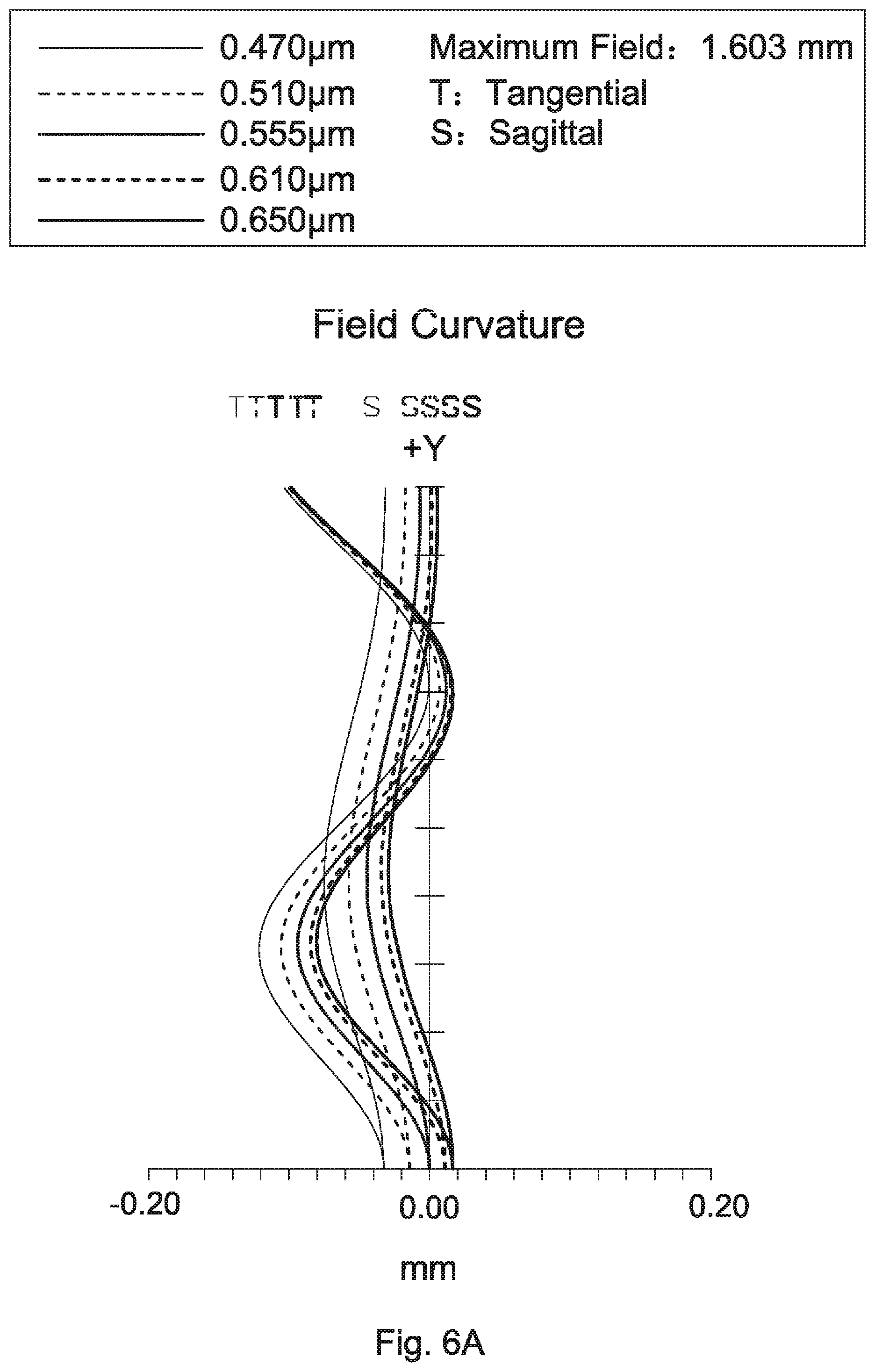
[0035] FIG. 6A depicts a field curvature diagram of the lens assembly in accordance with the third embodiment of the invention;
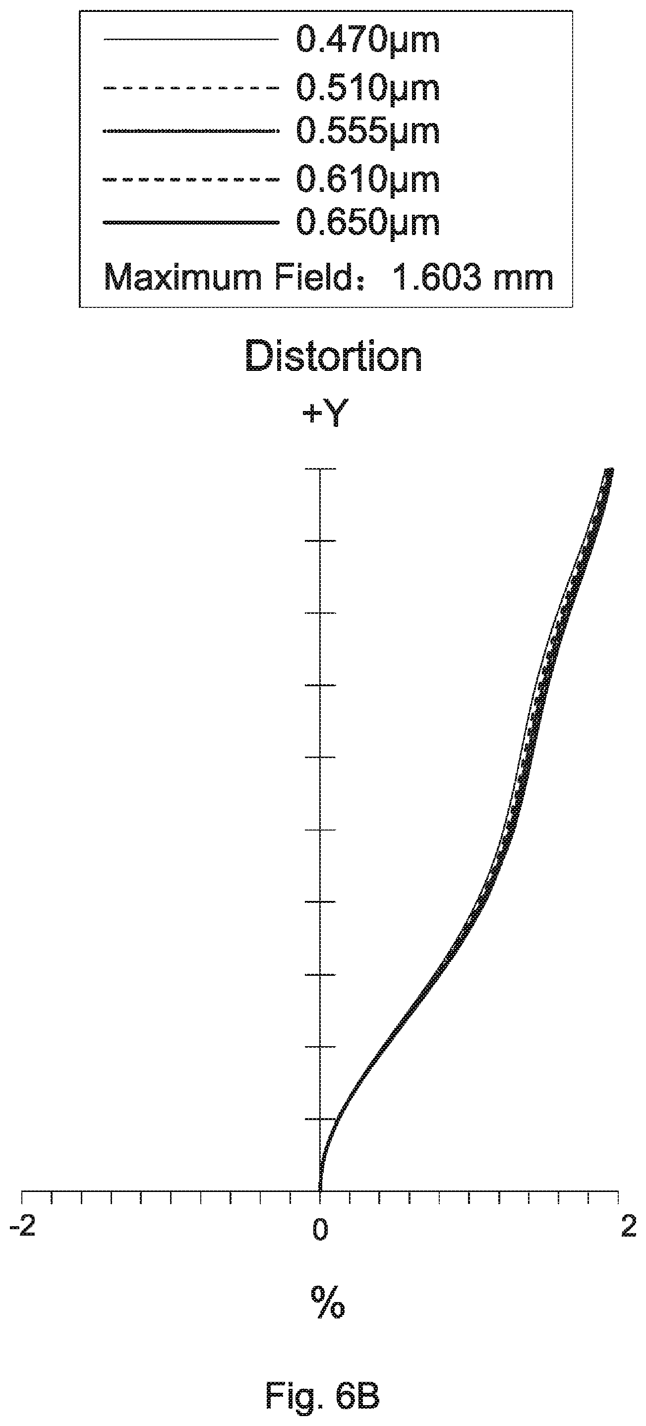
[0036] FIG. 6B is a distortion diagram of the lens assembly in accordance with the third embodiment of the invention;
[0037] FIG. 6C is a modulation transfer function diagram of the lens assembly in accordance with the third embodiment of the invention;
[0038] FIG. 7 is a lens layout and optical path diagram of a lens assembly in accordance with a fourth embodiment of the invention;
[0039] FIG. 8A depicts a field curvature diagram of the lens assembly in accordance with the fourth embodiment of the invention;
[0040] FIG. 8B is a distortion diagram of the lens assembly in accordance with the fourth embodiment of the invention;
[0041] FIG. 8C is a modulation transfer function diagram of the lens assembly in accordance with the fourth embodiment of the invention;
[0042] FIG. 9 is a lens layout and optical path diagram of a lens assembly in accordance with a fifth embodiment of the invention;
[0043] FIG. 10A depicts a field curvature diagram of the lens assembly in accordance with the fifth embodiment of the invention;
[0044] FIG. 10B is a distortion diagram of the lens assembly in accordance with the fifth embodiment of the invention;
[0045] FIG. 10C is a modulation transfer function diagram of the lens assembly in accordance with the fifth embodiment of the invention;
[0046] FIG. 11 is a lens layout and optical path diagram of a lens assembly in accordance with a sixth embodiment of the invention;
[0047] FIG. 12A depicts a field curvature diagram of the lens assembly in accordance with the sixth embodiment of the invention;
[0048] FIG. 12B is a distortion diagram of the lens assembly in accordance with the sixth embodiment of the invention;
[0049] FIG. 12C is a modulation transfer function diagram of the lens assembly in accordance with the sixth embodiment of the invention;
[0050] FIG. 13 is a lens layout and optical path diagram of a lens assembly in accordance with a seventh embodiment of the invention;
[0051] FIG. 14A depicts a field curvature diagram of the lens assembly in accordance with the seventh embodiment of the invention;
[0052] FIG. 14B is a distortion diagram of the lens assembly in accordance with the seventh embodiment of the invention;
[0053] FIG. 14C is a modulation transfer function diagram of the lens assembly in accordance with the seventh embodiment of the invention;
[0054] FIG. 15 is a lens layout and optical path diagram of a lens assembly in accordance with an eighth embodiment of the invention;
[0055] FIG. 16A depicts a field curvature diagram of the lens assembly in accordance with the eighth embodiment of the invention;
[0056] FIG. 16B is a distortion diagram of the lens assembly in accordance with the eighth embodiment of the invention;
[0057] FIG. 16C is a modulation transfer function diagram of the lens assembly in accordance with the eighth embodiment of the invention;
[0058] FIG. 17 is a lens layout and optical path diagram of a lens assembly in accordance with a ninth embodiment of the invention;
[0059] FIG. 18A depicts a field curvature diagram of the lens assembly in accordance with the ninth embodiment of the invention;
[0060] FIG. 18B is a distortion diagram of the lens assembly in accordance with the ninth embodiment of the invention;
[0061] FIG. 18C is a modulation transfer function diagram of the lens assembly in accordance with the ninth embodiment of the invention;
[0062] FIG. 19 is a lens layout and optical path diagram of a lens assembly in accordance with a tenth embodiment of the invention;
[0063] FIG. 20A depicts a field curvature diagram of the lens assembly in accordance with the tenth embodiment of the invention;
[0064] FIG. 20B is a distortion diagram of the lens assembly in accordance with the tenth embodiment of the invention;
[0065] FIG. 20C is a modulation transfer function diagram of the lens assembly in accordance with the tenth embodiment of the invention;
[0066] FIG. 21 is a lens layout and optical path diagram of a lens assembly in accordance with a eleventh embodiment of the invention;
[0067] FIG. 22A depicts a field curvature diagram of the lens assembly in accordance with the eleventh embodiment of the invention;
[0068] FIG. 22B is a distortion diagram of the lens assembly in accordance with the eleventh embodiment of the invention;
[0069] FIG. 22C is a modulation transfer function diagram of the lens assembly in accordance with the eleventh embodiment of the invention;
[0070] FIG. 23 is a lens layout and optical path diagram of a lens assembly in accordance with a twelfth embodiment of the invention;
[0071] FIG. 24A depicts a field curvature diagram of the lens assembly in accordance with the twelfth embodiment of the invention;
[0072] FIG. 24B is a distortion diagram of the lens assembly in accordance with the twelfth embodiment of the invention;
[0073] FIG. 24C is a modulation transfer function diagram of the lens assembly in accordance with the twelfth embodiment of the invention;
[0074] FIG. 25 is a lens layout and optical path diagram of a lens assembly in accordance with a thirteenth embodiment of the invention;
[0075] FIG. 26A depicts a field curvature diagram of the lens assembly in accordance with the thirteenth embodiment of the invention;
[0076] FIG. 26B is a distortion diagram of the lens assembly in accordance with the thirteenth embodiment of the invention; and
[0077] FIG. 26C is a modulation transfer function diagram of the lens assembly in accordance with the thirteenth embodiment of the invention.
DETAILED DESCRIPTION OF THE INVENTION
[0078] The following description is made for the purpose of illustrating the general principles of the invention and should not be taken in a limiting sense. The scope of the invention is best determined by reference to the appended claims.
[0079] The present invention provides a lens assembly including a first lens, a second lens, a third lens, and a fourth lens. The first lens is with positive refractive power and includes a concave surface facing an object side and a convex surface facing an image side. The second lens is with negative refractive power and includes a concave surface facing the object side. The third lens is with positive refractive power. The fourth lens is with refractive power and includes a concave surface facing the image side. The first lens, the second lens, the third lens, and the fourth lens are arranged in order from the object side to the image side along an optical axis. The lens assembly satisfies: TTL/f>1.2; wherein TTL is a total length of optical system of the lens assembly and f is an effective focal length of the lens assembly.
[0080] The present invention provides another lens assembly including a first lens, a second lens, a third lens, a fourth lens, and a reflective element. The first lens is with positive refractive power and includes a convex surface facing an image side. The second lens is with negative refractive power and includes a concave surface facing an object side. The third lens is with positive refractive power. The fourth lens is with refractive power and includes a concave surface facing the image side. The reflective element includes a reflective surface. The first lens, the second lens, the third lens, and the fourth lens are arranged in order from the object side to the image side along an optical axis. The reflective element is disposed between the first lens and the fourth lens. The lens assembly satisfies: 2 mm<L<6 mm; wherein L is an interval from an object side surface of a lens closest to the object side to the reflective surface along the optical axis.
[0081] Referring to Table 1, Table 2, Table 4, Table 5, Table 7, Table 8, Table 10, Table 11, Table 13, Table 14, Table 16, Table 17, Table 19, Table 20, Table 22, Table 23, Table 25, Table 26, Table 28, Table 29, Table 31, Table 32, Table 34, Table 35, Table 37, and Table 38, wherein Table 1, Table 4, Table 7, Table 10, Table 13, Table 16, Table 19, Table 2 Table 25, Table 28, Table 31, Table 34, and Table 37 show optical specification in accordance with a first, second, third, fourth, fifth, sixth, seventh, eighth, ninth, tenth, eleventh, twelfth, and thirteenth embodiments of the invention respectively and Table 2, Table 5, Table 8, Table 11, Table 14, Table 17, Table 20, Table 23, Table 26, Table 29, Table 32, Table 35, and Table 38 show aspheric coefficients of each aspheric lens in Table 1, Table 4, Table 7, Table 10, Table 13, Table 16, Table 19, Table 22, Table 25, Table 28, Table 31, Table 34, and Table 37 respectively.
[0082] FIG. 1, FIG. 3, FIG. 5, FIG. 7, FIG. 9, FIG. 11, FIG. 13, FIG. 15, FIG. 17, 19, FIG. 21, FIG. 23, and FIG. 25 are lens layout and optical path diagrams of the lens assemblies in accordance with the first, second, third, fourth, fifth, sixth, seventh, eighth, ninth, tenth, eleventh, twelfth, and thirteenth embodiments of the invention respectively.
[0083] The first lenses L11, L21, L31, L41, L51, L61, L71, L81, L91, L101, L111, L121, L131 are with positive refractive power and made of glass or plastic material, wherein the image side surfaces S15, S23, S33, S43, S53, S63, S73, S83, S93, S105, S115, S125, S135 are convex surfaces and both of the object side surfaces S14, S22, S32, S42, S52, S62, S72, S82, S92, S104, S114, S124, S134 and image side surfaces S15, S23, S33, S43, S53, S63, S73, S83, S93, S105, S115, S125, S135 are aspheric surfaces.
[0084] The second lenses L12, L22, L32, L42, L52, L62, L72, L82, L92, L102, L112, L122, and L132 are with negative refractive power and made of glass or plastic material, wherein the object side surfaces S16, S24, S34, S44, S54, S67, S77, S87, S97, S106, S116, S126, S136 are concave surfaces and both of the object side surfaces S16, S24, S34, S44, S54, S67, S77, S87, S97, S106, S116, S126, S.I36 and image side surfaces S17, S25, S35, S45, S55, S68, S78, S88, S98, S107, S117, S127, S137 are aspheric surfaces.
[0085] The third lenses L13, L23, L33, L43, L53, L63, L73, L83, L93, L103, L113, L123, and L133 are with positive refractive power and made of glass or plastic material, herein the object side surfaces S18, S26, S36, S46, S56, S69, S79, S89, S99, S108, S118, S128, S138 are convex surfaces.
[0086] The fourth lenses L14, L24, L34, L44, L54, L64 L74, L84, L94, L104, L114, L124, L134 are made of glass or plastic material, wherein the image side surfaces S114, S212, S312, S412, S514, S612, S712, S814, S916, S1011, S1111, S1211, S1311 are concave surfaces and the image side surfaces S114, S212, S312, S412, S514, S612, S712, S814, S916, S1011, S1111, S1211, S1311 are aspheric surfaces.
[0087] In addition, the lens assemblies 1, 2, 3, 4, 5, 6, 7, 8, 9 satisfy at least one of the following conditions:
TTL/f>1.2; (1)
2 mm<L<6 mm; (2)
5<TTL/OD.sub.1<14; (3)
0.5<ID.sub.1/OD.sub.1<1.5; (4)
5 mm<ALOD<14 mm; (5)
0<TTL/ALOD<2; (6)
1<ALOD/f<4; (7)
1<(TTL+f)/f.sub.obj1<5; (8)
|f.sub.obj1|+|f.sub.obj2|<|f.sub.obj4|; (9)
-3 mm<f.sub.obj3<0 mm; (10)
|f.sub.obj4|<|f.sub.obj5|; (11)
FPD.sub.max<4 mm; (12)
-1<f.sub.obj3/f.sub.obj4<2; (13)
1<f.sub.obj1/L1T<4; (14)
0.2 mm.sup.2<L1T.times.L1SD<2.2 mm.sup.2; (15)
-4 mm.sup.2<L1T.times.R.sub.11<0 mm.sup.2; (16)
0.5<M1T/L1T<4; (17)
1<TTL/L<5; (18)
0<L/f<2.5; (19)
-2 mm<8.times.M1T-(OD.sub.2+OD.sub.3+OD.sub.4+OD.sub.5)<1 mm; (20)
[0088] wherein TTL is a total length of optical system of the lens assemblies 1, 2, 3, 4, 5, 6, 7, 8, 9 for the first to ninth embodiments, that is, an interval from the stops ST1, ST2, ST3, ST4, ST5, ST6, ST7, ST8, ST9 to the image planes IMA1, IMA2, IMA3, IMA4, IMA5, IMA6, IMA7, IMA8, IMA9 along the optical axes OA1, OA2, OA3, OA4, OA5, OA6, OA7, OA8, OA9 respectively, f is an effective focal length of the lens assemblies 1, 2, 4, 5, 6, 7, 8, 9 for the first to ninth embodiments, L is an interval from the object side surfaces S12, S22, S32, S42, S52, S62, S72, S82, S92 of the lenses L15, L21, L31, L41, L51, L61, L71, L81, L91 which are closest to the object side to the reflective surfaces S111, S29, S39, S49, S59, 565, S75, S85, S95 along the optical axes OA1, OA2, OA3, OA4, OA5, OA6, OA7, OA8, OA9 respectively for the first to ninth embodiments, OD.sub.1 is an effective optical diameter of the object side surfaces S12, S22, S32, 542, S52 of the lenses L15, L21, L31, L41, L51 which are the closest to the object side respectively for the first to fifth embodiments, OD.sub.2 is an effective optical diameter of the object side surfaces S87, S97 of the lenses L82, L92 which are the second close to the object side respectively for the eighth to ninth embodiments, OD.sub.3 is an effective optical diameter of the object side surfaces S89, S99 of the lenses L83, L93 which are the third close to the object side respectively for the eighth to ninth embodiments, OD.sub.4 is an effective optical diameter of the object side surfaces S811, S911 of the lenses L85, L96 which are the fourth close to the object side respectively for the eighth to ninth embodiments, OD.sub.5 is an effective optical diameter of the object side surfaces S813, S913 of the lenses L84, L95 which are the fifth close to the object side respectively for the eighth to ninth embodiments, ID.sub.1 is an effective optical diameter of the image side surfaces S13, S23, S33, S43, S53 of the lenses L15, L21, L31, L41, L51 which are the closest to the object side respectively for the first to fifth embodiments, ALOD is a total of the effective optical diameter of the object side surfaces of each lenses for the first to ninth embodiments, f.sub.obj1 is an effective focal length of the lenses L15, L21, L31, L41, L51, L61, L71, L81, L91 which are the closest to the object side for the first to ninth embodiments, that is, an effective focal length of the lens which is arranged in order from the object side and is ranged the first, f.sub.obj2 is an effective focal length of the lenses L11, L22, L32, L42, L52 which are the second close to the object side for the first to fifth embodiments, that is, an effective focal length of the lens which is arranged in order from the object side and is ranged the second, f.sub.obj3 is an effective focal length of the lenses L12, L63, L73, L83, L93 which are the third close to the object side for the first and sixth to ninth embodiments, that is, an effective focal length of the lens which is arranged in order from the object side and is ranged the third, f.sub.obj4 is an effective focal length of the lenses L13, L24, L34, L44, L54, L64, L74, L85, L96 which are the fourth close to the object side for the first to ninth embodiments, that is, an effective focal length of the lens which is arranged in order from the object side and is ranged the fourth, f.sub.obj5 is an effective focal length of the lens L14 which is the fifth close to the object side for the first embodiment, that is, an effective focal length of the lens which is arranged in order from the object side and is ranged the fifth, FPD.sub.max is a maximum effective optical diameter of the lenses on the object side of the reflective elements P1, P2, P3, P4, P5 for the first to fifth embodiments, L1T is a thickness of the first lenses L61, L71, L81, L91 along the optical axes OA6, OA7, OA8, OA9 for the sixth to ninth embodiments, M1T is an interval from the image side surfaces S63, S73, S83, S93 of the first lenses L61, L71, L81, L91 to the reflective surfaces S65, S75, S85, S95 along the optical axes OA6, OA7, OA8, OA9 respectively for the sixth to ninth embodiments, L1SD is an effective optical semi-diameter of the image side surfaces S63, S73, S83, S93 of the first lenses L61, L71, L81, L91 for the sixth to ninth embodiments, and R.sub.11 is a radius of curvature of the object side surfaces S62, S72, S82, S92 of the first lenses L61, L71, L81, L91 for the sixth to ninth embodiments. With the lens assemblies 1, 2, 3, 4, 5, 6, 7, 8, 9 satisfying at least one of the above conditions (1)-(20), the total lens length can be effectively shortened, the resolution can be effectively increased, the aberration can be effectively corrected, and the chromatic aberration can be effectively corrected.
[0089] In addition, the lens assemblies 10, 11, 13 satisfy at least one of the following conditions:
D=f/2, 2.85 mm.ltoreq.D.ltoreq.2.95 mm; (21)
55 degrees.ltoreq.FOV.ltoreq.65 degrees; (22)
8 mm.ltoreq.TTL1.ltoreq.9 mm; (23)
Nd.sub.5.gtoreq.1.9; (24)
0.5.ltoreq.L5T, E.ltoreq.1.47; (25)
0/.degree. C..ltoreq.TCE<10.times.10.sup.-6/.degree. C.; (26)
Vd.sub.5<20; (27)
2.2.gtoreq.Nd.sub.5.gtoreq.1.9; (28)
17<Vd.sub.5<20; (29)
[0090] wherein f is an effective focal length of the lens assemblies 10, 11, 12, 13 for the tenth to the thirteenth embodiments, D is an effective diameter of an entrance pupil of the lens assemblies 10, 11, 12, 13 for the tenth to thirteenth embodiments, FOV is a full field of view of the lens assemblies 10, 11, 12, 13 for the tenth to thirteenth embodiments, TTL1 is an interval from the object side surfaces S11, S21, S31, S41 of the fifth lenses L105, L115, L125, L135 to the image planes IMA10, IMA11, IMA12, IMA13 along the optical axes OA10, OA11, OA12, OA13 respectively for the tenth to thirteenth embodiments, Nd.sub.5 is an index of refraction of the fifth lens L105, L115, L125, L135 for the tenth to thirteenth embodiments, L5T is a thickness of the fifth lenses L105, L115, L125, L135 along the optical axes OA10, OA11, OA12, OA13 for the tenth to thirteenth embodiments, E is a thickness of the outermost periphery of the fifth lenses L105, L115, L125, L135 for the tenth to thirteenth embodiments, TCE is a coefficient of thermal expansion of the fifth lenses L105, L115, L125, L135 at 25 degrees Celsius for the tenth to thirteenth embodiments, and Vd.sub.5 is an Abbe number of the fifth lenses L105, L115, L125, L135 for the tenth to thirteenth embodiments. With the lens assemblies 10, 11, 12, 13 satisfying at least one of the above conditions (21)-(29), the total lens length can effectively shortened, the resolution can be effectively increased, the environmental temperature change can be effectively resisted, the aberration can be effectively corrected, and the chromatic aberration can be effectively corrected.
[0091] A detailed description of a lens assembly in accordance with a first embodiment of the invention is as follows. Referring to FIG. 1, the lens assembly 1 includes a stop ST1, a fifth lens L15, a first lens L11, a second lens L12, a third lens L13, a reflective element P1, a fourth lens L14, and an optical filter OF1, all of which are arranged in order from an object side to an image side along an optical axis OA1. The reflective element P1 includes an incident surface S110, a reflective surface S111, and an exit surface S112, wherein the incident surface S110 and the exit surface S112 are perpendicular to each other. The reflective surface S111 may contains a metal layer, such as a metal thin film layer of aluminum (Al), silver (Ag), etc., and the reflective surface S111 can be made to include metal layer in any suitable ways, such as coating a metal thin film layer. In this way, the color shift phenomenon and the occurrence of halo during imaging can be avoided, so that the color shift can be effectively improved, the point light source can be effectively concentrated, and has a good image quality for the lens assembly 1. In operation, the light from the object side is reflected by the reflective surface S111 to change the propagation direction and imaged on an image plane IMA1. The image plane IMA1 and the exit surface S112 are parallel to each other. In the first embodiment, the reflective element takes a prism as an example but is not limited thereto. For example, the reflective element may be a reflective mirror which only includes a reflective surface.
[0092] According to paragraphs [0079]-[0086], wherein: the fifth lens L15 is a meniscus lens with positive refractive power and made of glass or plastic material, wherein the object side surface S12 is a convex surface, the image side surface S13 is a concave surface, and both of the object side surface S12 and image side surface S13 are aspheric surfaces; the first lens L11 is a meniscus lens, wherein the object side surface S14 is a concave surface; the second lens L12 is a meniscus lens, wherein the image side surface S17 is a convex surface; the third lens L13 is a plane-convex lens, wherein the image side surface S19 is a plane surface and the object side surface S18 is an aspheric surface; the fourth lens L14 is a plane-concave lens with negative refractive power, wherein the object side surface S113 is a plane surface; and both of the object side surface S115 and image side surface S116 of the optical filter OF1 are plane surfaces.
[0093] With the above design of the lenses, reflective element P1, stop ST1, and at least any one of the conditions (1)-(20) satisfied, the lens assembly 1 can have an effective shortened total lens length, an effective increased resolution, an effective corrected aberration, and is capable of an effective corrected chromatic aberration.
[0094] Table 1 shows the optical specification of the lens assembly 1 in FIG. 1.
TABLE-US-00001 TABLE 1 Effective Focal Length = 2.69192 mm F-number = 2.6 Total Optical System Length = 6.354404 mm Field of View = 62.33 degrees Radius of Effective Surface Curvature Thickness Focal Length Number (mm) (mm) Nd Vd (mm) Remark S11 .infin. -0.05 Stop ST1 S12 1.920745 0.2653972 1.855472 36.86999 7.837847 The Fifth Lens L15 S13 2.514984 0.3620153 S14 -1.49846 0.8913461 1.72512 52.5106 1.196022 The First Lens L11 S15 -0.68846 0.1073452 S16 -0.48904 0.3073362 1.671339 19.2429 -2.73696 The Second Lens L12 S17 -0.83279 0.048041 S18 14.60879 0.4065464 1.606501 57.54 24.01075 The Third Lens L13 S19 .infin. 0 S110 .infin. 1.39 1.802 44.3 Reflective Element P1 Incident Surface S111 .infin. 1.39 1.802 44.3 Reflective Element P1 Reflective Surface S112 .infin. 0.03982983 Reflective Element P1 Exit Surface S113 .infin. 0.3286899 1.670997 20.16101 -84.1182 The Fourth Lens L14 S114 56.94673 0.3728562 S115 .infin. 0.145 1.5 60 Optical Filter OF1 S116 .infin. 0.3
[0095] The aspheric surface sa z of each aspheric lens in table 1 can be calculated by the following formula:
z=ch.sup.2/{1+[1-(k+1)c.sup.2h.sup.2].sup.1/2}+Ah.sup.4+Bh.sup.6+Ch.sup.- 8+Dh.sup.10+Eh.sup.12+Fh.sup.14+Gh.sup.16
where c is curvature, h is the vertical distance from the lens surface to the optical axis, k is conic constant and A, B, C, D, E, F and G are aspheric coefficients.
[0096] In the first embodiment, the conic constant k and the aspheric coefficients A, B, C, D, E, F, G of each aspheric lens are shown in Table 2.
TABLE-US-00002 TABLE 2 Surface A B C Number k E F G D S12 4.976822 0.083554694 0.34409237 -3.238094 3.1215641 68.051673 -342.36581 468.78044 S13 0.294968 0.20307365 -0.06816194 3.3441261 -78.801281 478.13625 -1388.0483 1402.5153 S14 -18.558 -1.0626488 2.9323527 -25.198071 10.426915 692.26689 -4272.6448 6704.9929 S15 -0.62533 0.22080619 0.013686309 -1.8516094 4.819221 -6.1047322 2.9726467 0.25724607 S16 -1.35718 0.37547258 -0.18473306 0.53075068 -3.100164 8.7872601 -9.3355906 3.3930467 S17 -0.86516 0.35868629 -0.03283751 0.25468627 -0.81134706 1.1538557 -0.88183494 0.34412961 S18 152.0305 0.07683288 -0.02409805 -0.01397754 -0.00419835 0.003333245 0.011395619 -0.0069344 S114 110.0914 0.009061355 0.005413381 0.000280848 -0.0003746 -4.9044E-05 -2.5169E-05 1.30282E-05
[0097] Table 3 shows the parameters and condition values for conditions (1)-(12) and (18)-(19) in accordance with the first embodiment of the invention. It can be seen from Table 3 that the lens assembly 1 of the first embodiment satisfies the conditions (1)-(12) and (18)-(19).
TABLE-US-00003 TABLE 3 L 3.778027 mm OD.sub.1 1.04 mm ID.sub.1 0.960858 mm ALOD 8.28542 mm f.sub.obj1 7.837847 mm f.sub.obj2 1.196022 mm f.sub.obj3 -2.73696 mm f.sub.obj4 24.01075 mm f.sub.obj5 -84.1182 mm TTL/f 2.360547 TTL/OD.sub.1 6.110004 ID.sub.1/OD.sub.1 0.923902 TTL/ALOD 0.766938 ALOD/f 3.077885 (TTL + f)/f.sub.obj1 1.154185 |f.sub.obj1| + |f.sub.obj2| 9.033869 mm FPD.sub.max 2.143724 mm TTL/L 1.681937 L/f 1.403469
[0098] By the above arrangements of the lenses, reflective element P1, and stop ST1, the lens assembly 1 of the first embodiment can meet the requirements of optical performance as seen in FIGS. 2A-2C.
[0099] It can be seen from FIG. 2A that the field curvature of tangential direction and sagittal direction in the lens assembly 1 of the first embodiment ranges from -1.2 mm to 0.04 mm. It can be seen from FIG. 2B that the distortion in the lens assembly 1 of the first embodiment ranges from -2% to 0%. It can be seen from FIG. 2C that the modulation transfer function of tangential direction and sagittal direction in the lens assembly 1 of the first embodiment ranges from 0.36 to 1.0.
[0100] It is obvious that the field curvature and the distortion of the lens assembly 1 of the first embodiment can be corrected effectively, and the resolution of the lens assembly 1 of the first embodiment can meet the requirement. Therefore, the lens assembly 1 of the first embodiment is capable of good optical performance.
[0101] Referring to FIG. 3, the lens assembly 2 includes a stop ST2, a first lens L21, a second lens L22, a third lens L23, a reflective element P2, a fourth lens L24, and an optical filter OF2, all of which are arranged in order from an object side to an image side along an optical axis OA2. The reflective element P2 includes an incident surface S28, a reflective surface S29, and an exit surface S210, wherein the incident surface S28 and the exit surface S210 are perpendicular to each other. The reflective surface S29 may contains a metal layer, such as a metal thin film layer of aluminum (Al), silver (Ag), etc., and the reflective surface S29 can be made to include metal layer in any suitable ways, such as coating a metal thin film layer. In this way, the color shift phenomenon and the occurrence of halo during imaging can be avoided, so that the color shift can be effectively improved, the point light source can be effectively concentrated, and has a good image quality for the lens assembly 2. In operation, the light from the object side is reflected by the reflective surface S29 to change the propagation direction and imaged on an image plane IMA2. The image plane IMA2 and the exit surface S210 are parallel to each other. In the second embodiment, the reflective element takes a prism as an example but is not limited thereto. For example, the reflective element may be a reflective mirror which only includes a reflective surface.
[0102] According to paragraphs [0079]-[0086], wherein: the first lens L21 is a biconvex lens, wherein the object side surface S22 is a convex surface; the second lens L22 is a meniscus lens, wherein the image side surface S25 is a convex surface; the third lens L23 is a plane-convex lens, wherein the image side surface S27 is a plane surface and the object side surface S26 is an aspheric surface; the fourth lens L24 is a plane-concave lens with negative refractive power and made of glass or plastic material, wherein the object side surface S211 is a plane surface; and both of the object side surface S213 and image side surface S214 of the optical filter OF2 are plane surfaces.
[0103] With the above design of the lenses, reflective element P2, stop ST2, and at least any one of the conditions (1)-(20) satisfied, the lens assembly 2 can have an effective shortened total lens length, an effective increased resolution, an effective corrected aberration, and is capable of an effective corrected chromatic aberration.
[0104] Table 4 shows the optical specification of the lens assembly 2 in FIG. 3.
TABLE-US-00004 TABLE 4 Effective Focal Length = 3.17744 mm F-number = 2.8 Total Optical System Length = 6.420778 mm Field of View = 53.29 degrees Radius of Effective Surface Curvature Thickness Focal Length Number (mm) (mm) Nd Vd (mm) Remark S21 .infin. -0.03 Stop ST2 S22 3.2631 0.977638 1.460871 50.28586 2.219825 The First Lens L21 S23 -1.27745 0.383133 S24 -0.50863 0.506806 1.766014 19.23837 -2.27626 The Second Lens L22 S25 -1.0262 0.05 S26 1.806555 0.411432 1.5352 56.11 3.364525 The Third Lens L23 S27 .infin. 0 S28 .infin. 1.45 1.802 44.3 Reflective Element P2 Incident Surface S29 .infin. 1.45 1.802 44.3 Reflective Element P2 Reflective Surface S210 .infin. 0 Reflective Element P2 Exit Surface S211 .infin. 0.3 1.671 19.24 -68.294 The Fourth Lens L24 S212 46.2536 0.25 S213 .infin. 0.21 1.5 60 Optical Filter OF2 S214 .infin. 0.431769
[0105] The definition of aspheric surface sag z of each aspheric lens in table 4 is the same as that of in Table 1, and is not described here again.
[0106] In the second embodiment, the conic constant k and the aspheric coefficients A, B, C, D, E, F, G of each aspheric lens are shown in Table 5.
TABLE-US-00005 TABLE 5 Surface A B C Number k E F G D S22 0.074745 -0.048011492 -0.3028321 1.6353412 -5.9820629 7.4167268 -1.9108243 1.0042208 S23 0.011904 -0.1828205 0.47158168 -1.6667905 3.1545451 -3.1499386 1.0549963 -0.25722916 S24 -0.6883 0.52533852 0.07700536 0.73537126 -1.5005463 2.0444956 -1.5328175 0.61504974 S25 -0.45923 0.072598913 0.06002844 0.10395908 -0.15761884 0.065592419 0.00191003 -0.00640127 S26 -12.3712 0.016757851 -0.0149707 0.00115345 0.000765445 -0.000158888 -0.00019911 1.93E-05 S212 99.85161 0.016564398 -0.0009307 -0.00020828 3.70E-06 1.85E-07 -1.38E-07 2.90E-08
[0107] Table 6 shows the parameters and condition values for conditions (1)-(9), (12), and (18)-(19) in accordance with the second embodiment of the invention. It can be seen from Table 6 that the lens assembly 2 of the second embodiment satisfies the conditions (1)-(9), (12), and (18)-(19).
TABLE-US-00006 TABLE 6 L 3.779009 mm OD.sub.1 1.14468 mm ID.sub.1 1.51875 mm ALOD 7.823504 mm f.sub.obj1 2.219825 mm f.sub.obj2 -2.27626 mm f.sub.obj4 -68.294 mm TTL/f 2.020739 TTL/OD.sub.1 5.609234 ID.sub.1/OD.sub.1 1.32679 TTL/ALOD 0.820704 ALOD/f 2.462204 (TTL + f)/f.sub.obj1 4.323862 |f.sub.obj1| + |f.sub.obj2| 4.496082 mm FPD.sub.max 2.40044 mm TTL/L 1.699064 L/f 1.189325
[0108] By the above arrangements of the lenses, reflective element P2, and stop ST2, the lens assembly 2 of the second embodiment can meet the requirements of optical performance as seen in FIGS. 4A-4C.
[0109] It can be seen from FIG. 4A that the field curvature of tangential direction and sagittal direction in the lens assembly 2 of the second embodiment ranges from -0.09 mm to 0.04 mm. It can be seen from FIG. 4B that the distortion in the lens assembly 2 of the second embodiment ranges from 0% to 2%. It can be seen from FIG. 4C that the modulation transfer function of tangential direction and sagittal direction in the lens assembly 2 of the second embodiment ranges from 0.23 to 1.0.
[0110] It is obvious that the field curvature and the distortion of the lens assembly 2 of the second embodiment can be corrected effectively, and the resolution of the lens assembly 2 of the second embodiment can meet the requirement. Therefore, the lens assembly 2 of the second embodiment is capable of good optical performance.
[0111] Referring to FIG. 5, the lens assembly 3 includes a stop ST3, a first lens L31, a second lens L32, a third lens L33, a reflective element P3, a fourth lens L34, and an optical filter OF3, all of which are arranged in order from an object side to an image side along an optical axis OA3. The reflective element P3 includes an incident surface S38, a reflective surface S39, and an exit surface S310, wherein the incident surface S38 and the exit surface S310 are perpendicular to each other. The reflective surface S39 may contains a metal layer, such as a metal thin film layer of aluminum (Al), silver (Ag), etc., and the reflective surface S39 can be made to include metal layer in any suitable ways, such as coating a metal thin film layer. In this way, the color shift phenomenon and the occurrence of halo during imaging can be avoided, so that the color shift can be effectively improved, the point light source can be effectively concentrated, and has a good image quality for the lens assembly 3. In operation, the light from the object side is reflected by the reflective surface S39 to change the propagation direction and imaged on an image plane IMA3. The image plane IMA3 and the exit surface S310 are parallel to each other. In the third embodiment, the reflective element takes a prism as an example but is not limited thereto. For example, the reflective element may be a reflective mirror which only includes a reflective surface.
[0112] According to paragraphs [0079]-[0086], wherein: the first lens L31 is a meniscus lens, wherein the object side surface S32 is a concave surface; the second lens L32 is a meniscus lens, wherein the image side surface S35 is a convex surface; the third lens L33 is a meniscus lens, wherein the image side surface S37 is a concave surface and both of the object side surface S36 and image side surface S37 are aspheric surfaces; the fourth lens L34 is a meniscus lens with negative refractive power and made of glass or plastic material, wherein the object side surface S311 is a convex surface and the object side surface S311 is an aspheric surface; and both of the object side surface S313 and image side surface S314 of the optical filter OF3 are plane surfaces.
[0113] With the above design of the lenses, reflective element P3, stop ST3, and at least any one of the conditions (1)-(20) satisfied, the lens assembly 3 can have an effective shortened total lens length, an effective increased resolution, an effective corrected aberration, and is capable of an effective corrected chromatic aberration.
[0114] Table 7 shows the optical specification of the lens assembly 3 in FIG. 5.
TABLE-US-00007 TABLE 7 Effective Focal Length = 3.07095 mm F-number = 2.48 Total Optical System Length = 6.737603 mm Field of View = 54.88 degrees Radius of Effective Surface Curvature Thickness Focal Length Number (mm) (mm) Nd Vd (mm) Remark S31 .infin. 0.05 Stop ST3 S32 -8.27838 1.032199 1.802637 42.46164 2.557175 The First Lens L31 S33 -1.74218 0.560109 S34 -0.59054 0.386854 1.671268 19.23837 -2.03744 The Second Lens L32 S35 -1.30509 0.047319 S36 1.449244 0.498884 1.593194 67.0001 2.594658 The Third Lens L33 S37 20.71585 0.027937 S38 .infin. 1.39 1.802 44.3 Reflective Element P3 Incident Surface S39 .infin. 1.39 1.802 44.3 Reflective Element P3 Reflective Surface S310 .infin. 0.063172 Reflective Element P3 Exit Surface S311 3.484569 0.3 1.671 25.9586 -41.9926 The Fourth Lens L34 S312 3.834537 0.3 S313 .infin. 0.145 1.5 60 Optical Filter OF3 S314 .infin. 0.54613
[0115] The definition of aspheric surface sag z of each aspheric lens in table 7 is the same as that of in Table 1, and is not described here again.
[0116] In the third embodiment, the conic constant k and the aspheric coefficients A, B, C, D, E, F, G of each aspheric lens are shown in Table 8.
TABLE-US-00008 TABLE 8 Surface A B C Number k E F G D S32 1.85692 -0.03283118 -0.51476486 2.357223 -6.3265202 8.7153023 -7.7991946 5.05023 S33 -2.19313 -0.14408601 0.2533266 -1.1187475 2.4235947 -2.42689 0.62311844 0.26997132 S34 -0.75595 0.68959987 -0.86578972 0.98166611 -0.44154887 0.57687114 -1.8244609 1.3934062 S35 -0.46648 0.12091949 -0.06434362 0.084589559 -0.1210699 0.071602666 -0.00895967 -0.00443879 S36 -10.8268 0.046370156 -0.03910288 0.012386566 -0.0003165 -0.00291462 0.000278475 3.96E-04 S37 20.52489 -0.00570729 0.001837149 -0.00231611 -0.00082079 -0.00048266 -0.00014138 0.000309606 S311 -5.24682 -0.03786211 -0.00555871 -0.0016182 0.000209891 0.000320484 4.64E-05 -2.53E-05 S312 -8.05917 0.000424071 -0.00995192 0.001154838 3.45E-04 6.23E-06 -7.09E-06 -1.25E-06
[0117] Table 9 shows the parameters and condition values for conditions (1)-(9), (12), and (18)-(19) in accordance with the third embodiment of the invention. It can be seen from Table 9 that the lens assembly 3 of the third embodiment satisfies the conditions (1)-(9), (12), and (18)-(19).
TABLE-US-00009 TABLE 9 L 3.9433 mm OD.sub.1 1.250318 mm ID.sub.1 1.4 mm ALOD 7.711868 mm f.sub.obj1 2.557175 mm f.sub.obj2 -2.03744 mm f.sub.obj4 -41.9926 mm TTL/f 2.19398 TTL/OD.sub.1 5.388711 ID.sub.1/OD.sub.1 1.119715 TTL/ALOD 0.873667 ALOD/f 2.511232 (TTL + f)/f.sub.obj1 3.835699 |f.sub.obj1| + |f.sub.obj2| 4.594618 mm FPD.sub.max 2.329588 mm TTL/L 1.70862 L/f 1.284065
[0118] By the above arrangements of the lenses, reflective element P3, and stop ST3, the lens assembly 3 of the third embodiment can meet the requirements of optical performance as seen in FIGS. 6A-6C.
[0119] It can be seen from FIG. 6A that the field curvature of tangential direction and sagittal direction in the lens assembly 3 of the third embodiment ranges from -0.12 mm to 0.02 mm. It can be seen from FIG. 6B that the distortion in the lens assembly 3 of the third embodiment ranges from 0% to 2%. It can be seen from FIG. 6C that the modulation transfer function of tangential direction and sagittal direction in the lens assembly 3 of the third embodiment ranges from 0.35 to 1.0.
[0120] It is obvious that the field curvature and the distortion of the lens assembly 3 of the third embodiment can be corrected effectively, and the resolution of the lens assembly 3 of the third embodiment can meet the requirement. Therefore, the lens assembly 3 of the third embodiment is capable of good optical performance.
[0121] Referring to FIG. 7, the lens assembly4 includes a stop ST4, a first lens L41, a second lens L42, a third lens L43, a reflective element P4, a fourth lens L44, a fifth lens L45, and an optical filter OF4, all of which are arranged in order from an object side to an image side along an optical axis OA4. The reflective element P4 includes an incident surface S48, a reflective surface S49, and an exit surface S410, wherein the incident surface S48 and the exit surface S410 are perpendicular to each other. The reflective surface S49 may contains a metal layer, such as a metal thin film layer of aluminum (Al), silver (Ag), etc., and the reflective surface S49 can be made to include metal layer in any suitable ways, such as coating a metal thin film layer. In this way, the color shift phenomenon and the occurrence of halo during imaging can be avoided, so that the color shift can be effectively improved, the point light source can be effectively concentrated, and has a good image quality for the lens assembly 4. In operation, the light from the object side is reflected by the reflective surface S49 to change the propagation direction and imaged on an image plane IMA4. The image plane IMA4 and the exit surface S410 are parallel to each other. In the fourth embodiment, the reflective element takes a prism as an example but is not limited thereto. For example, the reflective element may be a reflective mirror which only includes a reflective surface.
[0122] According to paragraphs [0079]-[0086], wherein: the first lens L41 is a meniscus lens, wherein the object side surface S42 is a concave surface; the second lens L42 is a meniscus lens, wherein the image side surface S45 is a convex surface; the third lens L43 is a meniscus lens, wherein the image side surface S47 is a concave surface and both of the object side surface S46 and image side surface S47 are aspheric surfaces; the fourth lens L44 is a meniscus lens with negative refractive power and made of glass or plastic material, wherein the object side surface S411 is a convex surface and the object side surface S411 is an aspheric surface; the fifth lens L45 is a biconvex lens with positive refractive and made of glass or plastic material, wherein the object side surface S413 is a convex surface, the image side surface S414 is a convex surface, and both of the object side surface S413 and image side surface S414 are aspheric surfaces; and both of the object side surface S415 and image side surface S416 of the optical filter OF4 are plane surfaces.
[0123] With the above design of the lenses, reflective element P4, stop ST4, and at least any one of the conditions (1)-(20) satisfied, the lens assembly 4 can have an effective shortened total lens length, an effective increased resolution, an effective corrected aberration, and is capable of an effective corrected chromatic aberration.
[0124] Table 10 shows the optical specification of the lens assembly 4 in FIG. 7.
TABLE-US-00010 TABLE 10 Effective Focal Length = 3.06825 mm F-number = 2.48 Total Optical System Length = 7.097378 mm Field of View = 55.00 degrees Radius of Effective Surface Curvature Thickness Focal Length Number (mm) (mm) Nd Vd (mm) Remark S41 .infin. 0.07 Stop ST4 S42 -5.54134 0.989287 1.801505 39.99998 2.861517 The First Lens L41 S43 -1.75691 0.542297 S44 -0.59747 0.354514 1.671268 19.23837 -2.17272 The Second Lens L42 S45 -1.2466 0.047319 S46 1.463613 0.498884 1.592617 67.00001 2.631132 The Third Lens L43 S47 19.9944 0.081931 S48 .infin. 1.42 1.802 44.3 Reflective Element P4 Incident Surface S49 .infin. 1.42 1.802 44.3 Reflective Element P4 Reflective Surface S410 .infin. 0.130012 Reflective Element P4 Exit Surface S411 3.350262 0.3 1.671 19.23999 -136.303 The Fourth Lens L44 S412 3.350728 0.239519 S413 124.3329 0.232795 1.5352 56.11 11.16685 The Fifth Lens L45 S414 -6.29564 0.1 S415 .infin. 0.145 1.5 60 Optical Filter OF4 S416 .infin. 0.525821
[0125] The definition of aspheric surface sag z of each asp lens in table 10 is the same as that of in Table 1, and is not described here again.
[0126] In the fourth embodiment, the conic constant k and the aspheric coefficients A, B, C, D, E, F, G of each aspheric lens are shown in Table 11.
TABLE-US-00011 TABLE 11 Surface A B C Number k E F G D S42 1.219274 -0.03602155 -0.4856594 2.2884042 -6.4411208 9.0615729 -7.1735785 3.2656249 S43 -1.999641 -0.15262273 0.24937921 -1.0908768 2.404109 -2.5037565 0.53624724 0.53232278 S44 -0.7158636 0.65344018 -0.87515526 1.0760046 -0.45984854 0.3591053 -1.9976787 1.9645166 S45 -0.5362424 0.13140721 -0.07993976 0.074686371 -0.11486832 0.076430574 -0.01043467 -0.00370993 S46 -9.851534 0.054265844 -0.03613012 0.011437864 -0.00064248 -0.00257327 0.000552514 0.000189864 S47 100.2754 -0.0024418 0.001481947 -0.00150654 -0.00053277 -0.00073606 -0.00035132 0.00035109 S411 -6.801962 -0.04175006 -0.00681522 -0.00180852 0.000357034 0.000347889 4.17E-05 -3.38E-05 S412 -8.924384 -0.00026158 -0.0102123 0.001078722 0.000247299 -1.73E-05 -1.02E-05 -5.86E-08 S413 4322.146 0.008810033 -0.00177261 -0.00050394 -5.76E-05 1.88E-06 1.60E-06 2.04E-07 S414 -3.81E+15 -0.00550205 0.000286846 0.000182882 3.11E-05 2.84E-06 -6.89E-07 -1.28E-07
[0127] Table 12 shows the parameters and condition values for conditions (1)-(9), (12), and (18)-(19) in accordance with the fourth embodiment of the invention. It can be seen from Table 12 that the lens assembly 4 of the fourth embodiment satisfies the conditions (1)-(9), (12), and (18)-(19).
TABLE-US-00012 TABLE 12 L 3.934231 mm OD.sub.1 1.237022 mm ID.sub.1 1.4 mm ALOD 10.64337 mm f.sub.obj1 2.861517 mm f.sub.obj2 -2.17272 mm f.sub.obj4 -136.303 mm TTL/f 2.313168 TTL/OD.sub.1 5.737471 ID.sub.1/OD.sub.1 1.13175 TTL/ALOD 0.666836 ALOD/f 3.468872 (TTL + f)/f.sub.obj1 3.552531 |f.sub.obj1| + |f.sub.obj2| 5.034233 mm FPD.sub.max 2.377948 mm TTL/L 1.804006 L/f 1.282239
[0128] By the above arrangements of the lenses, reflective element P4, and stop ST4, the lens assembly 4 of the fourth embodiment can meet the requirements of optical performance as seen in FIGS. 8A-8C.
[0129] It can be seen from FIG. 8A that the field curvature of tangential direction and sagittal direction in the lens assembly 4 of the fourth embodiment ranges from -0.12 mm to 0.02 mm. It can be seen from FIG. 8B that the distortion in the lens assembly 4 of the fourth embodiment ranges from -0.15% to 0.3%. It can be seen from FIG. 8C that the modulation transfer function of tangential direction and sagittal direction in the lens assembly 4 of the fourth embodiment ranges from 0.41 to 1.0.
[0130] It is obvious that the field curvature and the distortion of the lens assembly 4 of the fourth embodiment can be corrected effectively, and the resolution of the lens assembly 4 of the fourth embodiment can meet the requirement. Therefore, the lens assembly 4 of the fourth embodiment is capable of good optical performance.
[0131] Referring to FIG. 9, the lens assembly 5 includes a stop ST5, a first lens L51, a second lens L52, a third lens L53, a reflective element P5, a fifth lens L55, a fourth lens L54, and an optical filter OF5, all of which are arranged in order from an object side to an image side along an optical axis OA5. The reflective element P5 includes an incident surface S58, a reflective surface S59, and an exit surface S510, wherein the incident surface S58 and the exit surface S510 are perpendicular to each other. The reflective surface S59 may contains a metal layer, such as a metal thin film layer of aluminum (Al), silver (Ag), etc., and the reflective surface S59 can be made to include metal layer in any suitable ways, such as coating a metal thin film layer. In this way, the color shift phenomenon and the occurrence of halo during imaging can be avoided, so that the color shift can be effectively improved, the point light source can be effectively concentrated, and has a good image quality for the lens assembly 5. In operation, the light from the object side is reflected by the reflective surface S59 to change the propagation direction and imaged on an image plane IMA5. The image plane IMA5 and the exit surface S510 are parallel to each other. In the fifth embodiment, the reflective element takes a prism as an example but is not limited thereto. For example, the reflective element may be a reflective mirror which only includes a reflective surface.
[0132] According to paragraphs [0079]-[0086], wherein: the first lens L51 is a meniscus lens, wherein the object side surface S52 is a concave surface; the second lens L52 is a meniscus lens, wherein the image side surface S55 is a convex surface; the third lens L53 is a meniscus lens, wherein the image side surface S57 is a concave surface and both of the object side surface S56 and image side surface S57 are aspheric surfaces; the fifth lens L55 is a biconvex lens with positive refractive power and made of glass or plastic material, wherein the object side surface S511 is a convex surface, the image side surface S512 is a convex surface, and both of the object side surface S511 and image side surface S512 are aspheric surfaces; the fourth lens L54 is a meniscus lens with negative refractive power and made of glass or plastic material, wherein the object side surface S513 is a convex surface and the object side surface S513 is an aspheric surface; and both of the object side surface S515 and image side surface S516 of the optical filter OF5 are plane surfaces.
[0133] With the above design of the lenses, reflective element P5, stop ST5, and at least any one of the conditions (1)-(20) satisfied, the lens assembly 5 can have an effective shortened total lens length, an effective increased resolution, an effective corrected aberration, and is capable of an effective corrected chromatic aberration.
[0134] Table 13 shows the optical specification of the lens assembly 5 in FIG. 9.
TABLE-US-00013 TABLE 13 Effective Focal Length = 3.06826 mm F-number = 2.6 Total Optical System Length = 7.341773 mm Field of View = 54.96 degrees Radius of Effective Surface Curvature Thickness Focal Length Number (mm) (mm) Nd Vd (mm) Remark S51 .infin. 0.07 Stop ST5 S52 -4.39042 0.983474 1.801502 39.99999 3.061721 The First Lens L51 S53 -1.73644 0.563924 S54 -0.60926 0.312458 1.671268 19.23837 -2.17488 The Second Lens L52 S55 -1.2539 0.047319 S56 1.490571 0.498884 1.59183 67.00004 2.268636 The Third Lens L53 S57 20.06779 0.139272 S58 .infin. 1.4231 1.802 44.3 Reflective Element P5 Incident Surface S59 .infin. 1.4231 1.802 44.3 Reflective Element P5 Reflective Surface S510 .infin. 0.074659 Reflective Element P5 Exit Surface S511 7.081442 0.428229 1.5352 56.11 6.312641 The Fifth Lens L55 S512 -6.36407 0.111748 S513 2.396352 0.3 1.671 19.23996 -11.8433 The Fourth Lens L54 S514 1.751843 0.4 S515 .infin. 0.145 1.5 60 Optical Filter OF5 S516 .infin. 0.420607
[0135] The definition of aspheric surface sag z of each aspheric lens in table 13 is the same as that of in Table 1, and is not described here again.
[0136] In the fifth embodiment, the conic constant k and the aspheric coefficients A, B, C, D, E, F, G of each aspheric lens are shown in Table 14.
TABLE-US-00014 TABLE 14 Surface A B C Number k E F G D S52 0.352.453 -0.03422112 -0.45802357 2.2693686 -6.4909192 9.046813 -6.9516731 3.2895086 S53 -2.40009 -0.14450985 0.21758413 -1.0525346 2.4379204 -2.5465537 0.35927899 0.77433394 S54 -0.71996 0.64455126 -0.91019912 1.0470208 -0.41689718 0.45189718 -1.8985688 1.7996989 S55 -0.55955 0.13370732 -0.07924532 0.071852647 -0.11445011 0.086059915 -0.00541713 -0.00829265 S56 -11.8096 0.053502886 -0.03530097 0.012714455 0.00016147 -0.00237709 0.000397931 0.000120715 S57 -99.9462 -0.00815003 0.002534206 0.000202537 1.66E-05 -0.00065772 -0.00045445 0.000285441 S511 -12.3666 -0.00360962 -0.0020524 7.16E-06 0.000127816 4.28E-05 4.33E-06 -2.58E-06 S512 -16.6528 -0.00027334 0.000661254 0.000162137 6.74E-05 2.97E-05 1.43E-05 3.51E-06 S513 -10.8915 -0.04134912 -0.00522074 -0.00145687 0.000258147 0.000332458 4.75E-05 -2.70E-05 S514 -6.6787 -0.00560482 -0.01002556 0.001256401 0.000350737 4.80E-06 -7.74E-06 -1.34E-06
[0137] Table 15 shows the parameters and condition values for conditions (1)-(9), (12), and (18)-(19) in accordance with the fifth embodiment of the invention. It can be seen from Table 15 that the lens assembly 5 of the fifth embodiment satisfies the conditions (1)-(9), (12), and (18)-(19).
TABLE-US-00015 TABLE 15 L 3.96843 mm OD.sub.1 1.248812 mm ID.sub.1 1.44 mm ALOD 11.30868 mm f.sub.obj1 3.061721 mm f.sub.obj2 -2.17488 mm f.sub.obj4 6.312641 mm TTL/f 2.392813 TTL/OD.sub.1 5.879006 ID.sub.1/OD.sub.1 1.153096 TTL/ALOD 0.649216 ALOD/f 3.685698 (TTL + f)/f.sub.obj1 3.400059 |f.sub.obj1| + |f.sub.obj2| 5.236605 mm FPD.sub.max 2.469688 mm TTL/L 1.850045 L/f 1.293381
[0138] By the above arrangements of the lenses, reflective element P5, and stop ST5, the lens assembly 5 of the fifth embodiment can meet the requirements of optical performance as seen in FIGS. 10A-10C.
[0139] It can be seen from FIG. 10A that the field curvature of tangential direction and sagittal direction in the lens assembly 5 of the fifth embodiment ranges from -0.10 mm to 0.025 mm. It can be seen from FIG. 10B that the distortion in the lens assembly 5 of the fifth embodiment ranges from 0% to 2%. It can be seen from FIG. 10C that the modulation transfer function of tangential direction and sagittal direction in the lens assembly 5 of the fifth embodiment ranges from 0.40 to 1.0.
[0140] It is obvious that the field curvature and the distortion of the lens assembly 5 of the fifth embodiment can be corrected effectively, and the resolution of the lens assembly 5 of the fifth embodiment can meet the requirement. Therefore, the lens assembly 5 of the fifth embodiment is capable of good optical performance.
[0141] Referring to FIG. 11, the lens assembly 6 includes a stop ST6, a first lens L61, a reflective element P6, a second lens L62, a third lens L63, a fourth lens L64, and an optical filter OF6, all of which are arranged in order from an object side to an image side along an optical axis OA6. The reflective element P6 includes an incident surface S64, a reflective surface S65, and an exit surface S66, wherein the incident surface S64 and the exit surface S66 are perpendicular to each other. The reflective surface S65 may contains a metal layer, such as a metal thin film layer of aluminum (Al), silver (Ag), etc., and the reflective surface S65 can be made to include metal layer in any suitable ways, such as coating a metal thin film layer. In this way, the color shift phenomenon and the occurrence of halo during imaging can be avoided, so that the color shift can be effectively improved, the point light source can be effectively concentrated, and has a good image quality for the lens assembly 6. In operation, the light from the object side is reflected by the reflective surface S65 to change the propagation direction and imaged on an image plane IMA6. The image plane IMA6 and the exit surface S66 are parallel to each other. In the sixth embodiment, the reflective element takes a prism as an example but is not limited thereto. For example, the reflective element may he a reflective mirror which only includes a reflective surface.
[0142] According to paragraphs [0079]-[0086], wherein: the first lens L61 is a meniscus lens, wherein the object side surface S62 is a concave surface; the second lens L62 is a biconcave lens, wherein the image side surface S68 is a concave surface; the third lens L63 is a biconvex lens, wherein the image side surface 8610 is a convex surface and both of the object side surface S609 and image side surface S610 are aspheric surfaces; the fourth lens L64 is a meniscus lens with negative refractive power and made of glass or plastic material, wherein the object side surface S611 is a convex surface and the object side surface S611 is an aspheric surface; and both of the object side surface S613 and image side surface S614 of the optical filter OF6 are plane surfaces.
[0143] With the above design of the lenses, reflective element P6, stop ST6, and at least any one of the conditions (1)-(20) satisfied, the lens assembly 6 can have an effective shortened total lens length, an effective increased resolution, an effective corrected aberration, and is capable of an effective corrected chromatic aberration.
[0144] Table 16 shows the optical specification of the lens assembly 6 in FIG. 11.
TABLE-US-00016 TABLE 16 Effective Focal Length = 2.4918 mm F-number = 2.48 Total Optical System Length = 7.254615 mm Field of View = 38.78 degrees Radius of Effective Surface Curvature Thickness Focal Length Number (mm) (mm) Nd Vd (mm) Remark S61 .infin. 0.08432 Stop ST6 S62 -2.54656 1.430805 1.85605 40.28218 2.574553 The First Lens L61 S63 -1.49194 0.011211 S64 .infin. 1.303 2.0033 28.32 Reflective Element P6 Incident Surface S65 .infin. 1.303 2.0033 28.32 Reflective Element P6 Reflective Surface S66 .infin. 0.09988 Reflective Element P6 Exit Surface S67 -2.50592 0.281861 1.651 19.24 -2.513553 The Second Lens L62 S68 5.060772 0.023067 S69 4.41957 1.42177 1.5352 56.11 1.960286 The Third Lens L63 S610 -1.22633 0.012178 S611 1.320806 0.291233 1.671 19.23991 -8.025317 The Fourth Lens L64 S612 0.967984 0.35 S613 .infin. 0.145 1.5 60 Optical Filter OF6 S614 .infin. 0.49729
[0145] The aspheric surface sag z of each aspheric lens in table 16 can be calculated by the following formula:
z=ch.sup.2/{1+[1-(k+1)c.sup.2h.sup.2].sup.1/2}+Ah.sup.4+Bh.sup.6+Ch.sup.- 8+Dh.sup.10+Eh.sup.12+Fh.sup.14+Gh.sup.16+Hh.sup.18+Ih.sup.20
[0146] where c is curvature, h is the vertical distance from the lens surface to the optical axis, k is conic constant and A, B, C, D, G, H and I are aspheric coefficients.
[0147] In the sixth embodiment, the conic constant k and the aspheric coefficients A, B, C, D, E, G, H, I of each aspheric lens are shown in Table 17.
TABLE-US-00017 TABLE 17 Surface A B C D Number k F G H I E S62 13.75142 0.059633072 0.197975902 -1.353695553 6.011150013 32.00738145 -197.1765565 -516.6148698 4973.695118 -8072.082431 S63 0.844515 0.075082368 0.025370142 -0.078201244 0.373403036 -0.286249347 -0.896557483 2.03681989 -1.42041644 0.297002462 S67 0.315678 -0.19884293 0.03114807 0.03883311 -0.0023693 -0.01358974 -0.0041441 0.003413 0.002526 -0.0011816 S68 11.50862 -0.04801084 -0.01774108 0.01732643 0.009153 -0.0014184 -0.001882 -0.00062629 0.0002499 0.0001749 S69 -7.72515 -0.05136858 0.02018952 -0.01897868 -0.006259 0.006072 0.005693 -0.0016121 -0.0024039 0.0008936 S610 -3.31646 -0.02385783 0.02126333 -0.00022589 -0.0031994 -0.00056687 -0.000065107 -0.00032328 -0.00011925 0.0001142 S611 -1.10491 0.19171951 0.02421953 -0.01275306 -0.0037512 -0.00054874 0.0002613 0.0001886 0.00002875 -0.000021294 S612 -2.37611 0.20702235 -0.03961328 -0.0069432 0.001398 0.0005286 -0.00002298 -0.000038561 -4.8794E-06 0.000003042
[0148] Table 18 shows the parameters and condition values for conditions (1)-(2), (5)-(6), (8), and (13)-(19) in accordance with the sixth embodiment of the invention. It can be seen from Table 18 that the lens assembly 6 of the sixth embodiment satisfies the conditions (1)-(2), (5)-(6), (8), and (13)-(19).
TABLE-US-00018 TABLE 18 L 2.745337 mm ALOD 9.774 mm f.sub.obj1 2.574553 mm f.sub.obj3 1.960286 mm f.sub.obj4 -8.025317 mm L1T 1.430805 mm L1SD 0.877 mm R.sub.11 -2.54656 mm M1T 1.31421124 mm TTL/f 3.294779 TTL/ALOD 0.83937 (TTL + f)/f.sub.obj1 4.154623 f.sub.obj3/f.sub.obj4 -0.2443 L1T .times. L1SD 1.25411 mm.sup.2 L1T .times. R.sub.11 -3.64158 mm.sup.2 f.sub.obj1/L1T 1.8 mm M1T/L1T 0.91902 TTL/L 2.98834 L/f 1.102545
[0149] By the above arrangements of the lenses, reflective element P6, and stop ST6, the lens assembly 6 of the sixth embodiment can meet the requirements of optical performance as seen in FIGS. 12A-12C.
[0150] It can be seen from FIG. 12A that the field curvature of tangential direction and sagittal direction in the lens assembly 6 of the sixth embodiment ranges from -0.1 mm to 0.3 mm. It can be seen from FIG. 12B that the distortion in the lens assembly 6 of the sixth embodiment ranges from 0% to 2%. It can be seen from FIG. 12C that the modulation transfer function of tangential direction and sagittal direction in the lens assembly 6 of the sixth embodiment ranges from 0.49 to 1.0.
[0151] It is obvious that the field curvature and the distortion of the lens assembly 6 of the sixth embodiment can be corrected effectively, and the resolution of the lens assembly 6 of the sixth embodiment can meet the requirement. Therefore, the lens assembly 6 of the sixth embodiment is capable of good optical performance.
[0152] Referring to FIG. 13, the lens assembly 7 includes a stop ST7, a first lens L71, a reflective element P7, a second lens L72, a third lens L73, a fourth lens L74, and an optical filter OF7, all of which are arranged in order from an object side to an image side along an optical axis OA7. The reflective element P7 includes an incident surface S74, a reflective surface S75, and an exit surface S76, wherein the incident surface S74 and the exit surface S76 are perpendicular to each other. The reflective surface S75 may contains a metal layer, such as a metal thin film layer of aluminum (Al), silver (Ag), etc., and the reflective surface S75 can be made to include metal layer in any suitable ways, s as coating a metal thin film layer. In this way, the color shift phenomenon and the occurrence of halo during imaging can be avoided, so that the color shift can be effectively improved, the point light source can be effectively concentrated, and has a good image quality for the lens assembly 7. In operation, the light from the object side is reflected by the reflective surface S75 to change the propagation direction and imaged on an image plane IMA7. The image plane IMA7 and the exit surface S76 are parallel to each other. In the seventh embodiment, the reflective element takes a prism as an example but is not limited thereto. For example, the reflective element may be a reflective mirror which only includes a reflective surface.
[0153] According to paragraphs [0079]-[0086], wherein: the first lens L71 is a meniscus lens, wherein the object side surface S72 is a concave surface; the second lens L72 is a biconcave lens, wherein the image side surface S78 is a concave surface; the third lens L73 is a biconvex lens, wherein the image side surface S710 is a convex surface and both of the object side surface S709 and image side surface S710 are aspheric surfaces; the fourth lens L74 is a meniscus lens with negative refractive power and made of glass or plastic material, wherein the object side surface S711 is a convex surface and the object side surface S711 is an aspheric surface; and both of the object side surface S713 and image side surface S714 of the optical filter OF7 are plane surfaces.
[0154] With the above design of the lenses, reflective element P7, stop ST7, and at least any one of the conditions (1)-(20) satisfied, the lens assembly 7 can have an effective shortened total lens length, an effective increased resolution, an effective corrected aberration, and is capable of an effective corrected chromatic aberration.
[0155] Table 19 shows the optical specification of the lens assembly 7 in FIG. 13.
TABLE-US-00019 TABLE 19 Effective Focal Length = 2.688 mm F-number = 2.48 Total Optical System Length = 6.990387 mm Field of View = 37.15 degrees Radius of Effective Surface Curvature Thickness Focal Length Number (mm) (mm) Nd Vd (mm) Remark S71 .infin. 0.11165 Stop ST7 S72 -2.17683 0.861726 1.85605 40.2822 2.936058 The First Lens L71 S73 -1.3829 0.011817 S74 .infin. 1.511484 2.003303 28.31998 Reflective Element P7 Incident Surface S75 .infin. 1.511484 2.003303 28.31998 Reflective Element P7 Reflective Surface S76 .infin. 0.1053 Reflective Element P7 Exit Surface S77 -3.3371 0.2971 1.651 19.24 -2.580873 The Second Lens L72 S78 3.5698 0.0243 S79 3.2047 1.4424 1.5352 56.11 1.537502 The Third Lens L73 S710 -0.9372 0.0128 S711 1.2686 0.307 1.671 19.23991 -2.804457 The Fourth Lens L74 S712 0.6863 0.4689 S713 .infin. 0.145 1.5 60 Optical Filter OF7 S714 .infin. 0.179424
[0156] The definition of aspheric surface sag z of each aspheric lens in table 19 is the same as that of in Table 16, and is not described here again.
[0157] In the seventh embodiment, the conic constant k and the aspheric coefficients A, B, C, D, E, F, G, H, I of each aspheric lens are shown in Table 20.
TABLE-US-00020 TABLE 20 Surface A B C D Number k F G H I E S72 12.37051 0.048262563 0.389555332 -1.145030981 -3.704327987 69.06398288 -78.86702201 -873.1214579 3076.709194 -2494.305293 S73 0.997786 0.04991879 0.080225825 -0.189381455 0.391873143 -0.055996169 -0.897002003 2.39169789 -0.957068478 -2.717302478 S77 2.316024 -0.0685 -0.0332 0.0216 0.0136 -0.0064636 -0.0057684 0.00085384 0.0019887 -0.00058658 S78 -0.65583 0.0424 -0.0359 -0.006035 0.0073692 0.0029372 -0.000059262 -0.00091777 -0.00026251 0.00017107 S79 -23.3047 -0.0221 0.027 -0.0186 -0.0087938 0.0030024 0.0056237 -0.00037447 -0.001833 0.00048667 S710 -3.44257 -0.0236 0.0207 -0.00061085 -0.0038854 -0.0038854 -0.00062128 0.00048696 0.0002905 -0.00010395 S711 -8.14832 0.0877 -0.00088187 -0.0078454 0.00092888 -0.00090514 0.00028164 0.00019802 0.000021087 -0.000020786 S712 -3.68024 0.0877 -0.00088187 -0.0078454 0.00092888 0.00038536 -0.000055828 -0.000010893 2.2467E-06 -1.005E-07
[0158] Table 21 shows the parameters and condition values for conditions (1)-(2), (5)-(6), (8), and (13)-(19) in accordance with the seventh embodiment of the invention. It can be seen from Table 21 that the lens assembly 7 of the seventh embodiment satisfies the conditions (1)-(2), (5)-(6), (8), and (13)-(19).
TABLE-US-00021 TABLE 21 L 2.385027 mm ALOD 9.74 mm f.sub.obj1 2.936058 mm f.sub.obj3 1.537502 mm f.sub.obj4 -2.804457 mm L1T 0.861726 mm L1SD 0.67 mm R.sub.11 -2.17683 mm M1T 1.52330112 mm TTL/f 2.955357 TTL/ALOD 0.815606 (TTL + f)/f.sub.obj1 3.621253 f.sub.obj3/f.sub.obj4 -0.54807 L1T .times. L1SD 0.577356 mm.sup.2 L1T .times. R.sub.11 -1.87583 mm.sup.2 f.sub.obj1/L1T 3.407116 mm M1T/L1T 1.76773 TTL/L 3.33078 L/f 0.887287
[0159] By the above arrangements of the lenses, reflective element P7, and stop ST7, the lens assembly 7 of the seventh embodiment can meet the requirements of optical performance as seen in FIGS. 14A-14C.
[0160] It can be seen from FIG. 14A that the field curvature of tangential direction and sagittal direction in the lens assembly 7 of the seventh embodiment ranges from -0.05 mm to 0.03 mm. It can be seen from FIG. 14B that the distortion in the lens assembly 7 of the seventh embodiment ranges from 0% to 2%. It can be seen from FIG. 14C that the modulation transfer function of tangential direction and sagittal direction in the lens assembly 7 of the seventh embodiment ranges from 0.42 to 1.0.
[0161] It is obvious that the field curvature and the distortion of the lens assembly 7 of the seventh embodiment can be corrected effectively, and the resolution of the lens assembly 7 of the seventh embodiment can meet the requirement. Therefore, the lens assembly 7 of the seventh embodiment is capable of good optical performance.
[0162] Referring to FIG. 15, the lens assembly 8 includes a stop ST8, a first lens L81, a reflective element P8, a second lens L82, a third lens L83, a fifth lens L85, a fourth lens L84, and an optical filter OF8, all of which are arranged in order from an object side to an image side along an optical axis OA8. The reflective element P8 includes an incident surface S84, a reflective surface S85, and an exit surface S86, wherein the incident surface S84 and the exit surface S86 are perpendicular to each other. The reflective surface S85 may contains a metal layer, such as a metal thin film layer of aluminum (Al), silver (Ag), etc., and the reflective surface S85 can be made to include metal layer in any suitable ways, such as coating a metal thin film layer. In this way, the color shift phenomenon and the occurrence of halo during imaging can be avoided, so that the color shift can be effectively improved, the point light source can be effectively concentrated, and has a good image quality for the lens assembly 8. In operation, the light from the object side is reflected by the reflective surface S85 to change the propagation direction and imaged on an image plane IMA8. The image plane IMA8 and the exit surface S86 are parallel to each other. In the eighth embodiment, the reflective element takes a prism as an example but is not limited thereto. For example, the reflective element may be a reflective mirror which only includes a reflective surface.
[0163] According to paragraphs [0079]-[0086], wherein: the first lens L81 is a meniscus lens, wherein the object side surface S82 is a concave surface; the second lens L82 is a biconcave lens, wherein the image side surface S88 is a concave surface; the third lens L83 is a biconvex lens, wherein the image side surface S810 is a convex surface and both of the object side surface S809 and image side surface S810 are aspheric surfaces; the fifth lens L85 is a biconvex lens with positive refractive power and made of glass or plastic material, wherein the object side surface S811 is a convex surface, the image side surface S812 is a convex surface, and both of the object side surface S811 and image side surface S812 are aspheric surfaces; the fourth lens L84 is a meniscus lens with positive refractive power and made of glass or plastic material, wherein the object side surface S813 is a convex surface and the object side surface S813 is an aspheric surface; and both of the object side surface S815 and image side surface S816 of the optical filter OF8 are plane surfaces.
[0164] With the above design of the lenses, reflective element P8, stop ST8, and at least any one of the conditions (1)-(20) satisfied, the lens assembly 8 can have an effective shortened total lens length, an effective increased resolution, an effective corrected aberration, and is capable of an effective corrected chromatic aberration.
[0165] Table 22 shows the optical specification of the lens assembly 8 in FIG. 15.
TABLE-US-00022 TABLE 22 Effective Focal Length = 1.118 mm F-number = 2.48 Total Optical System Length = 5.572 mm Field of View = 36.473 degrees Radius of Effective Surface Curvature Thickness Focal Length Number (mm) (mm) Nd Vd (mm) Remark S81 .infin. 0.076 Stop ST8 S82 -1.061 1.056 1.86 40.3 2.398 The First Lens L81 S83 -1.025 0.020 S84 .infin. 0.925 2.00 28.3 Reflective Element P8 Incident Surface S85 .infin. 0.925 2.00 28.3 Reflective Element P8 Reflective Surface S86 .infin. 0.020 Reflective Element P8 Exit Surface S87 -6.728 0.210 1.67 19.2 -1.573 The Second Lens L82 S88 1.283 0.024 S89 1.426 0.718 1.54 56.1 1.898 The Third Lens L83 S810 -2.941 0.020 S811 6.313 0.610 1.54 56.1 1.815 The Fifth Lens L85 S812 -1.114 0.020 S813 1.501 0.210 1.67 19.200 11.588 The Fourth Lens L84 S814 1.751 0.200 S815 .infin. 0.145 1.5 64.2 Optical Filter OF8 S816 .infin. 0.393
[0166] The definition of aspheric surface sag z of each aspheric lens in table 22 is the same as that of in Table 16, and is not described here again.
[0167] In the eighth embodiment, the conic constant k and the aspheric coefficients A, B, C, D, E, F, G, H, I of each aspheric lens are shown in Table 23.
TABLE-US-00023 TABLE 23 Surface A B C D Number k F G H I E S82 1.14E+01 2.00E+00 -6.32E+01 3.22E+03 -5.78E+04 -9.53E+04 1.30E+07 1.19E+08 -6.22E+09 4.68E+10 S83 1.12E+00 1.18E-01 6.40E+00 -5.46E+01 5.95E+01 1.85E+03 -3.45E+03 -7.98E+04 4.66E+05 -7.63E+05 S87 -6.04E+01 -3.87E-01 2.54E-01 3.38E-01 -2.42E-01 -8.21E-01 -1.34E-01 1.55E+00 -1.36E-01 -6.10E-01 S88 2.89E-01 2.86E-02 1.67E-01 2.98E-01 -1 18E-01 -7.13E-01 -4.53E-02 7.81E-01 5.01E-01 -6.02E-01 S89 -8.71E-01 -1.15E-02 9.54E-02 -2.77E-01 -1.75E-02 6.66E-02 2.65E-02 1.43E+00 -2.90E+00 1.65E+00 S810 0.00E+00 3.77E-01 -5.98E-01 -1.89E-01 2.21E-01 -3.70E-01 -1.54E-02 -7.37E-01 3.66E+00 -2.47E+00 S811 4.00E+01 -1.03E-01 1.36E-01 -1.72E-01 -2.12E-01 -1.01E-01 6.34E-01 1.30E-01 -1.21E+00 8.56E-01 S812 -5.24E+00 -4.70E-01 3.61E-01 6.64E-01 9.76E-02 -1.17E+00 -2.16E+00 2.99E+00 5.85E-01 -9.94E-01 S813 9.42E-01 8.21E-01 4.03E-01 -3.52E-01 -4.16E-01 -5.14E-01 -1.60E-01 1.02E+00 1.24E+00 -1.49E+00 S814 2.50E-00 1.33E+00 -6.98E-01 -4.07E-01 2.21E-01 3.53E-01 8.33E-01 -1.36E+00 -1.43E+00 2.04E+00
[0168] Table 24 shows the parameters and condition values for conditions (1)-(2), (5)-(6), (8), and (13)-(20) in accordance with the eighth embodiment of the invention. It can be seen from Table 24 that the lens assembly 8 of the eighth embodiment satisfies the conditions (1)-(2), (5)-(6), (8), and (13)-(20).
TABLE-US-00024 TABLE 24 L 2.001 mm ALOD 7.832 mm f.sub.obj1 2.398 mm f.sub.obj3 1.898 mm f.sub.obj4 1.815 mm L1T 1.056 mm L1SD 0.457 mm R.sub.11 -1.061 mm M1T 0.945 mm OD.sub.2 1.79 mm OD.sub.3 1.89 mm OD.sub.4 1.89 mm OD.sub.5 1.78 mm TTL/f 5.832737 TTL/ALOD 0.83261 (TTL + f)/f.sub.obj1 3.185571 f.sub.obj3/f.sub.obj4 1.04573 L1T .times. L1SD 0.482592 mm.sup.2 L1T .times. R.sub.11 -1.12042 mm.sup.2 f.sub.obj1/L1T 2.270833 mm M1T/L1T 0.89489 TTL/L 3.258871 L/f 1.789803 8 .times. M1T - 0.05 mm (OD.sub.2 + OD.sub.3 + OD.sub.4 + OD.sub.5)
[0169] By the above arrangements of the lenses, reflective element P8, and stop ST8, the lens assembly 8 of the eighth embodiment can meet the requirements of optical performance as seen in FIGS. 16A-16C.
[0170] It can be seen from FIG. 16A that the field curvature of tangential direction and sagittal direction in the lens assembly 8 of the eighth embodiment ranges from -0.4 mm to 0.15 mm. It can be seen from FIG. 16B that the distortion in the lens assembly 8 of the eighth embodiment ranges from 0% to 2.75%. It can be seen from FIG. 16C that the modulation transfer function of tangential direction and sagittal direction in the lens assembly 8 of the eighth embodiment ranges from 0.33 to 1.0.
[0171] It is obvious that the field curvature and the distortion of the lens assembly 8 of the eighth embodiment can be corrected effectively, and the resolution of the lens assembly 8 of the eighth embodiment can meet the requirement. Therefore, the lens assembly 8 of the eighth embodiment is capable of good optical performance.
[0172] Referring to FIG. 17, the lens assembly 9 includes a stop ST9, a first lens L91, a reflective element P9, a second lens L92, a third lens L93, a sixth lens L96, a fifth lens L95, a fourth lens L94, and an optical filter OF9, all of which are arranged in order from an object side to an image side along an optical axis OA9. The reflective element P9 includes an incident surface S94, a reflective surface S95, and an exit surface S96, wherein the incident surface S94 and the exit surface S96 are perpendicular to each other. The reflective surface S95 may contains a metal layer, such as a metal thin film layer of aluminum (Al), silver (Ag), etc., and the reflective surface S95 can be made to include metal layer in any suitable ways, such as coating a metal thin film layer. In this way, the color shift phenomenon and the occurrence of halo during imaging can be avoided, so that the color shift can be effectively improved, the point light source can be effectively concentrated, and has a good image quality for the lens assembly 9. In operation, the light from the object side is reflected by the reflective surface S95 to change the propagation direction and imaged on an image plane IMA9. The image plane IMA9 and the exit surface S96 are parallel to each other. In the ninth embodiment, the reflective element takes a prism as an example but is not limited thereto. For example, the reflective element may be a reflective mirror which only includes a reflective surface.
[0173] According to paragraphs [0079]-[0086], wherein: the first lens L91 is a meniscus lens, wherein the object side surface S92 is a concave surface; the second lens L92 is a biconcave lens, wherein the image side surface S98 is a concave surface; the third lens L93 is a biconvex lens, wherein the image side surface S910 is a convex surface and both of the object side surface S909 and image side surface S910 are aspheric surfaces; the sixth lens L96 is a meniscus lens with negative refractive power and made of glass or plastic material, wherein the object side surface S911 is a concave surface, the image side surface S912 is a convex surface, and both of the object side surface S911 and image side surface S912 are aspheric surfaces; the fifth lens L95 is a meniscus lens with positive refractive power and made of glass or plastic material, wherein the object side surface S913 is a concave surface, the image side surface S914 is a convex surface, and both of the object side surface S913 and image side surface S914 are aspheric surfaces; the fourth lens L94 is a meniscus lens with positive refractive power and made of glass or plastic material, wherein the object side surface S915 is a convex surface and the object side surface S915 is an aspheric surface; and both of the object side surface S917 and image side surface S918 of the optical filter OF9 are plane surfaces.
[0174] With the above design of the lenses, reflective element P9, stop ST9, and at least any one of the conditions (1)-(20) satisfied, the lens assembly 9 can have an effective shortened total lens length, an effective increased resolution, an effective corrected aberration, and is capable of an effective corrected chromatic aberration.
[0175] Table 25 shows the optical specification of the lens assembly 9 in FIG. 17.
TABLE-US-00025 TABLE 25 Effective Focal Length = 1.082 mm F-number = 2.48 Total Optical System Length = 6.099 mm Field of View = 37.489 degrees Radius of Effective Surface Curvature Thickness Focal Length Number (mm) (mm) Nd Vd (mm) Remark S91 .infin. 0.077 Stop ST9 S92 -0.934 1.078 1.9 40.3 2.74 The First Lens L91 S93 -1.028 0.030 S94 .infin. 0.996 2.0 28.3 Reflective Element P9 Incident Surface S95 .infin. 0.996 2.0 28.3 Reflective Element P9 Reflective Surface S96 .infin. 0.020 Reflective Element P9 Exit Surface S97 -39.255 0.205 1.7 19.2 -3.469 The Second Lens L92 S98 2.506 0.020 S99 3.433 0.818 1.5 56.1 3.15 The Third Lens L93 S910 -3.058 0.020 S911 -7.805 0.212 1.7 19.2 -204.946 The Sixth Lens L96 S912 -8.360 0.020 S913 -11.948 0.526 1.5 56.1 5.855 The Fifth Lens L95 S914 -2.527 0.020 S915 0.928 0.441 1.5 56.1 2.091 The Fourth Lens L94 S916 4.453 0.200 S917 .infin. 0.145 1.5 64.2 Optical Filter OF9 S918 .infin. 0.275
[0176] The definition of aspheric surface sag z of each aspheric lens in table 25 is the same as that of in Table 16, and is not described here again.
[0177] In the ninth embodiment, the conic constant k and the aspheric coefficients A, B, C, D, E, F, G, H, I of each aspheric lens are shown in Table 26.
TABLE-US-00026 TABLE 26 Surface A B C D Number k F G H I E S92 7.05E+00 2.00E+00 -6.32E+01 3.22E+03 -5.78E+04 -9.53E+04 1.30E+07 1.19E+08 -6.22E+09 4.68E+10 S93 1.30E+00 1.18E-01 6.40E+00 -5.46E+01 5.95E+01 1.85E+03 -3.45E+03 -7.98E+04 4.66E+05 -7.63E+05 S97 -1.95E+04 -3.87E-01 2.54E-01 3.38E-01 -2.42E-01 -8.21E-01 -1.34E-01 1.55E+00 -1.36E-01 -6.10E-01 S98 4.61E+00 2.86E-02 1.67E-01 2.98E-01 -1.18E-01 -7.13E-01 -4.53E-02 7.81E-01 5.01E-01 -6.02E-01 S99 -3.37E+01 -1.15E-02 9.54E-02 -2.77E-01 -1.75E-02 6.66E-02 2.65E-02 1.43E+00 -2.90E+00 1.65E+00 S910 -3.16E-01 3.77E-01 -5.98E-01 -1.89E-01 2.21E-01 -3.70E-01 -1.54E-02 -7.37E-01 3.66E+00 -2.47E+00 S911 0.00E+00 -1.03E-01 1.36E-01 -1.72E-01 -2.12E-01 -1.01E-01 6.34E-01 1.30E-01 -1.21E+00 8.56E-01 S912 0.00E+00 -4.70E-01 3.61E-01 6.64E-01 9.76E-02 -1.17E+00 -2.16E+00 2.99E+00 5.85E-01 -9.94E-01 S913 0.00E+00 -1.03E-01 1.36E-01 -1.72E-01 -2.12E-01 -1.01E-01 6.34E-01 1.30E-01 -1.21E+00 8.56E-01 S914 1.69E+00 -4.70E-01 3.61E-01 6.64E-01 9.76E-02 -1.17E+00 -2.16E+00 2.99E+00 5.85E-01 -9.94E-01 S915 -1.50E+00 8.21E-01 4.03E-01 -3.52E-01 -4.16E-01 -5.14E-01 -1.60E-01 1.02E+00 1.24E+00 -1.49E+00 S916 0.00E+00 1.33E+00 -6.98E-01 -4.07E-01 2.21E-01 3.53E-01 8.33E-01 -1.36E+00 -1.43E+00 2.04E+00
[0178] Table 27 shows the parameters and condition values for conditions (1)-(2), (5)-(6), (8), and (13)-(20) in accordance with the ninth embodiment of the invention. It can be seen from Table 27 that the lens assembly 9 of the ninth embodiment satisfies the conditions (1)-(2), (5)-(6), (8), and (13)-(20).
TABLE-US-00027 TABLE 27 L 2.104 mm ALOD 10.363 mm f.sub.obj1 2.74 mm f.sub.obj3 3.15 mm f.sub.obj4 -204.949 mm L1T 1.078 mm L1SD 0.48585 mm R.sub.11 -0.934 mm M1T 1.026 mm OD.sub.2 1.99 mm OD.sub.3 2 mm OD.sub.4 1.99 mm OD.sub.5 2 mm TTL/f 6.513863 TTL/ALOD 0.680112 (TTL + f)/f.sub.obj1 2.967153 f.sub.obj3/f.sub.obj4 -0.01537 L1T .times. L1SD 0.523746 mm.sup.2 L1T .times. R.sub.11 -1.00685 mm.sup.2 f.sub.obj1/L1T 2.541744 mm M1T/L1T 0.95176 TTL/L 3.34981 L/f 1.944547 8 .times. M1T - -0.012 mm (OD.sub.2 + OD.sub.3 + OD.sub.4 + OD.sub.5)
[0179] By the above arrangements of the lenses, reflective element P9, and stop ST9, the lens assembly 9 of the ninth embodiment can meet the requirements of optical performance as seen in FIGS. 18A-18C.
[0180] It can be seen from FIG. 18A that the field curvature of tangential direction and sagittal direction in the lens assembly 9 of the ninth embodiment ranges from -0.06 mm to 0.09 mm. It can be seen from FIG. 18B that the distortion in the lens assembly 9 of the ninth embodiment ranges from 0% to 4%. It can be seen from FIG. 18C that the modulation transfer function of tangential direction and sagittal direction in the lens assembly 9 of the ninth embodiment ranges from 0.33 to 1.0.
[0181] It is obvious that the field curvature and the distortion of the lens assembly 9 of the ninth embodiment can be corrected effectively, and the resolution of the lens assembly 9 of the ninth embodiment can meet the requirement. Therefore, the lens assembly 9 of the ninth embodiment is capable of good optical performance.
[0182] Referring to FIG. 19, the lens assembly 10 includes a fifth lens L105, a stop ST10, a first lens L101, a second lens L102, a third lens L103, a fourth lens L104, and an optical filter OF10, all of which are arranged in order from an object side to an image side along an optical axis OA10. In operation, the light from the object side is imaged on an image plane IMA10.
[0183] According to paragraphs [0079]-[0086], wherein: the fifth lens L105 is a meniscus lens with positive refractive power and made of glass or plastic material, wherein the object side surface S101 is a convex surface, the image side surface S102 is a concave surface, and both of the object side surface S101 and image side surface S102 are spherical surfaces; the first lens L101 is a meniscus lens, wherein the object side surface S104 is a concave surface and the image side surface S105 is a convex surface; the second lens L102 is a meniscus lens, wherein the object side surface S106 is a concave surface and the image side surface S107 is a convex surface; the third lens L103 is a biconvex lens, wherein the image side surface S109 is a convex surface and both of the object side surface S108 and image side surface S109 are spherical surfaces; the fourth lens L104 is a meniscus lens with negative refractive power and made of glass or plastic material, wherein the object side surface S1010 is a convex surface, the image side surface S1011 is a concave surface, and the object side surface S1010 is an aspheric surface; and both of the object side surface S1012 and image side surface S1013 of the optical filter OF10 are plane surfaces.
[0184] With the above design of the lenses, stop ST10, and at least any one of the conditions (21)-(29) satisfied, the lens assembly 10 can have an effective shortened total lens length, an effective increased resolution, an effective resisted environmental temperature change, an effective corrected aberration, and is capable of an effective corrected chromatic aberration.
[0185] If the value Nd.sub.5 of condition (24) is less than 1.9, the ability to control the optical effective diameter of the lens is decreased, so that the value of Nd.sub.5 must at least greater than or equal to 1.9. The best range of Nd.sub.5 is to satisfy the condition: 2.2.gtoreq.Nd.sub.5.gtoreq.1.9. When the condition (28): 2.2.gtoreq.Nd.sub.5.gtoreq.1.9 is satisfied, the lens assembly can be effectively miniaturized.
[0186] Table 28 shows the optical specification of the lens assembly 10 in FIG. 19.
TABLE-US-00028 TABLE 28 Effective Focal Length = 5.80646 mm F-number = 2.0 Total Lens Length = 8.55 mm Field of View = 55.00 degrees Radius of Effective Surface Curvature Thickness Focal Length Number (mm) (mm) Nd Vd (mm) Remark S101 3.95894 1.18417 1.945958 17.9439 7.133563 The Fifth Lens L105 S102 8.82867 0.40544 S103 .infin. 0.53815 Stop ST10 S104 -9.44949 0.32834 1.54392 55.9512 38.817584 The First Lens L101 S105 -6.57127 1.44769 S106 -1.41906 0.70612 1.66143 20.3729 -35.070688 The Second Lens L102 S107 -0.55294 0.04721 S108 7.90347 1.44236 1.94596 17.9439 6.039579 The Third Lens L103 S109 -16.02125 0.11366 S1010 4.57526 0.53893 1.66143 20.3729 -8.387423 The Fourth Lens L104 S1011 2.34787 0.55401 S1012 .infin. 0.70043 1.51680 64.2124 Optical Filter OF10 S1013 .infin. 0.54413
[0187] The definition of aspheric surface sag z of each aspheric lens in table 28 is the same as that of in Table 1, and is not described here again.
[0188] In the tenth embodiment, the conic constant k and the aspheric coefficients A, B, C, D, E, F, G of each aspheric lens are shown in Table 29.
TABLE-US-00029 TABLE 29 Surface A B C Number k E F G D S104 -201.36061 -0.038636149 0.020413122 -0.013355429 0.000050272 -0.000758228 0.002640600 -0.001183207 S105 -1.53417 -0.012580526 -0.003289361 -0.003195349 -0.001134968 0.000197044 0.000656148 -0.000357008 S106 -0.47215 0.017040780 0.001459691 -0.000672766 0.000419733 0.000364050 -0.000321983 0.000066342 S107 -1.10421 0.003023939 -0.001248133 0.000661656 0.000008801 -0.000011219 -0.000000121 0.000000344 S1010 -26.68405 -0.017531115 0.000030348 0.000256838 -0.000010924 -0.000001929 0.000000084 0.000000005 S1011 -6.45372 -0.014760078 0.001344553 -0.000149720 0.000019749 -0.000000548 -0.000000163 0.000000011
[0189] Table 30 shows the parameters and condition values for conditions (21)-(29) in accordance with the tenth embodiment of the invention. It can be seen from Table 30 that the lens assembly 10 of the tenth embodiment satisfies the conditions (21)-(29).
TABLE-US-00030 TABLE 30 D 2.9 mm L5T 1.18417 mm E 0.808552 mm TCE 6 .times. 10.sup.-6/.degree. C. L5T/E 1.46
[0190] By the above arrangements of the lenses and stop ST10, the lens assembly 10 of the tenth embodiment can meet the requirements of optical performance as seen in FIGS. 20A-20C.
[0191] It can be seen from FIG. 20A that the field curvature of tangential direction and sagittal direction in the lens assembly 10 of the tenth embodiment ranges from -0.03 mm to 0.05 mm. It can be seen from FIG. 20B that the distortion in the lens assembly 10 of the tenth embodiment ranges from 0% to 2.5%. It can be seen from FIG. 20C that the modulation transfer function of tangential direction and sagittal direction in the lens assembly 10 of the tenth embodiment ranges from 0.66 to 1.0.
[0192] It is obvious that the field curvature and the distortion of the lens assembly 10 of the tenth embodiment can be corrected effectively, and the resolution of the lens assembly 10 of the tenth embodiment can meet the requirement. Therefore, the lens assembly 10 of the tenth embodiment is capable of good optical performance.
[0193] Referring to FIG. 21, the lens assembly 11 includes a fifth lens L115, a stop ST11, a first lens L111, a second lens L112, a third lens L113, a fourth lens L114, and an optical filter OF11, all of which are arranged in order from an object side to an image side along an optical axis OA11. In operation, the light from the object side is imaged on an image plane IMA11.
[0194] According to paragraphs [0079]-[0086], wherein: the fifth lens L115 is a meniscus lens with positive refractive power and made of glass or plastic material, wherein the object side surface S111 is a convex surface, the image side surface S112 is a concave surface, and both of the object side surface S111 and image side surface S112 are spherical surfaces; the first lens L111 is a meniscus lens, wherein the object side surface S114 is a concave surface; the second lens L112 is a meniscus lens, wherein the image side surface S117 is a convex surface; the third lens L113 is a biconvex lens, wherein the image side surface S119 is a convex surface and both of the object side surface S118 and image side surface S119 are spherical surfaces; the fourth lens L114 is a meniscus lens with negative refractive power and made of glass or plastic material, wherein the object side surface S1110 is a convex surface and the object side surface S1110 is an aspheric surface; and both of the object side surface S1112 and image side surface S1113 of the optical filter OF11 are plane surfaces.
[0195] With the above design of the lenses, stop ST11, and at least any one of the conditions (21)-(29) satisfied, the lens assembly 11 can have an effective shortened total lens length, an effective increased resolution, an effective resisted environmental temperature change, an effective corrected aberration, and is capable of an effective corrected chromatic aberration.
[0196] If the value Vd.sub.5 of condition (27) is greater than 20, the ability of chromatic aberration correction of the fifth lens L115 is reduced, so that the value of Vd.sub.5 must at least less than 20. The best range of Vd.sub.5 is to satisfy the condition: 17<Vd.sub.5<20. When the condition (29): 17<Vd.sub.5<20 is satisfied, the chromatic aberration of the lens assembly can be effectively decreased.
[0197] Table 31 shows the optical specification of the lens assembly 11 in FIG. 21.
TABLE-US-00031 TABLE 31 Effective Focal Length = 5.81 mm F-number = 2.0 Total Lens Length = 9.04 mm Field of View = 55.038 degrees Radius of Effective Surface Curvature Thickness Focal Length Number (mm) (mm) Nd Vd (mm) Remark S111 4.107088 1.266335 1.945958 17.9439 7.22427 The Fifth Lens L115 S112 9.482251 0.336351 S113 .infin. 0.54772 Stop ST11 S114 -9.47203 0.40629 1.543915 55.9512 33.33143 The First Lens L111 S115 -6.2767 1.390833 S116 -1.3996 0.733813 1.661342 20.3729 -20.3528 The Second Lens L112 S117 -1.88921 0.047214 S118 7.524683 1.96791 1.945958 17.9439 6.044728 The Third Lens L113 S119 -17.3496 0.112765 S1110 4.458774 0.548079 1.661342 20.3729 -9.54765 The Fourth Lens L114 S1111 2.446003 0.476435 S1112 .infin. 0.700425 1.516797 64.2124 Optical Filter OF11 S1113 .infin. 0.508777
[0198] The definition of aspheric surface sag z of each aspheric lens in table 31 is the same as that of in Table 16, and is not described here again.
[0199] In the eleventh embodiment, the conic constant k and the aspheric coefficients A, B, C, D, E, F, G of each aspheric lens are shown in Table 32.
TABLE-US-00032 TABLE 32 Surface A B C Number k E F G D S114 -198.99125 -0.039080575 0.020841812 -0.01229672 0.000197748 -0.001131297 0.002470088 -0.001038633 S115 0.97126 -0.014389127 -0.001441984 -0.00298736 -0.001406179 0.000106232 0.000679002 0.000314135 S116 -0.47308 0.013078311 0.000608593 -0.000288588 0.000474103 0.00035647 -0.000323491 6.84E-05 S117 -1.01146 0.001487229 -0.000977573 0.000640356 2.96E-06 -6.95E-06 8.66E-07 2.91E-08 S1110 -22.98041 -0.017388991 -3.67E-05 0.000248808 -1.06E-05 -1.76E-06 9.80E-08 2.45E-09 S1111 -6.24639 -0.014596958 0.001317709 -0.000149159 2.00E-05 -5.18E-07 -1.64E-07 1.05E-08
[0200] Table 33 shows the parameters and condition values for conditions (21)-(29) in accordance with the eleventh embodiment of the invention. It can be seen from Table 32 that the lens assembly 11 of the eleventh embodiment satisfies the conditions (21)-(29).
TABLE-US-00033 TABLE 33 D 2.9029 mm L5T 1.266335 mm E 0.897992 mm TCE 6 .times. 10.sup.-6/.degree. C. L5T/E 1.41
[0201] By the above arrangements of the lenses and stop ST11, the lens assembly 11 of the eleventh embodiment can meet the requirements of optical performance as seen in FIGS. 22A-22C.
[0202] It can be seen from FIG. 22A that the field curvature of tangential direction and sagittal direction in the lens assembly 11 of the eleventh embodiment ranges from -0.04 mm to 0.05 mm. It can be seen from FIG. 22B that the distortion in the lens assembly 11 of the eleventh embodiment ranges from 0% to 1.6%. It can be seen from FIG. 22C that the modulation transfer function of tangential direction and sagittal direction in the lens assembly 11 of the eleventh embodiment ranges from 0.67 to 1.0.
[0203] It is obvious that the field curvature and the distortion of the lens assembly 11 of the eleventh embodiment can be corrected effectively, and the resolution of the lens assembly 11 of the eleventh embodiment can meet the requirement. Therefore, the lens assembly 11 of the eleventh embodiment is capable of good optical performance.
[0204] Referring to FIG. 23, the lens assembly 12 includes a fifth lens L125, a stop ST12, a first lens L121, a second lens L122, a third lens L123, a fourth lens L124, and an optical filter OF12, all of which are arranged in order from an object side to an image side along an optical axis OA12. In operation, the light from the object side is imaged on an image plane IMA12.
[0205] According to paragraphs [0079]-[0086], wherein: the fifth lens L125 is a meniscus lens with positive refractive power and made of glass or plastic material, wherein the object side surface S121 is a convex surface, the image side surface S122 is a concave surface, and both of the object side surface S121 and image side surface S122 are spherical surfaces; the first lens L121 is a meniscus lens, wherein the object side surface S124 is a concave surface; the second lens L122 is a meniscus lens, wherein the image side surface S127 is a convex surface; the third lens L123 is a biconvex lens, wherein the image side surface S129 is a convex surface and both of the object side surface S128 and image side surface S129 are spherical surfaces; the fourth lens L124 is a meniscus lens with negative refractive power and made of glass or plastic material, wherein the object side surface S1210 is a convex surface and the object side surface S1210 is an aspheric surface; and both of the object side surface S1212 and image side surface S1213 of the optical filter OF12 are plane surfaces.
[0206] With the above design of the lenses, stop ST12, and at least any one of the conditions (21)-(29) satisfied, the lens assembly 12 can have an effective shortened total lens length, an effective increased resolution, an effective resisted environmental temperature change, an effective corrected aberration, and is capable of an effective corrected chromatic aberration.
[0207] Table 34 shows the optical specification of the lens assembly 12 in FIG. 23.
TABLE-US-00034 TABLE 34 Effective Focal Length = 5.79 mm F-number = 2.0 Total Lens Length = 8.19 mm Field of View = 55.11 degrees Radius of Effective Surface Curvature Thickness Focal Length Number (mm) (mm) Nd Vd (mm) Remark S121 3.935692 1.186649 2.001784 19.325 6.802067 The Fifth Lens L125 S122 8.464791 0.290445 S123 .infin. 0.540718 Stop ST12 S124 -9.00662 0.393322 1.543915 55.9512 39.91597 The First Lens L121 S125 -6.42959 1.375738 S126 -1.40571 0.385239 1.661342 20.3729 -28.6481 The Second Lens L122 S127 -1.88118 0.047214 S128 8.423747 1.549774 1.945958 17.9439 6.274073 The Third Lens L123 S129 -15.7453 0.125701 S1210 5.192829 0.515782 1.661342 20.3729 -8.757644 The Fourth Lens L124 S1211 2.581012 0.542045 S1212 .infin. 0.700425 1.516797 64.2124 Optical Filter OF12 S1213 .infin. 0.532498
[0208] The definition of aspheric surface sag z of each aspheric lens in table 34 is the same as that of in Table 16, and is not described here again.
[0209] In the twelfth embodiment, the conic constant k and the aspheric coefficients A, B, C, D, E, F, G of each aspheric lens are shown in Table 35.
TABLE-US-00035 TABLE 35 Surface A B C Number k E F G D S124 -1.8218208 -0.037405167 0.021456633 -0.01302741 0.00016725 -0.000973744 0.00260212 -0.001125216 S125 -2.96846 -0.012075656 -0.002658559 -0.003085045 -0.001291418 0.000126268 0.000654463 -0.000315947 S126 -0.46591 0.017504217 0.000601285 -0.00064421 0.000503056 0.000376188 -0.000331765 6.89E-05 S127 -1.13584 0.003520561 -0.001180144 0.000692902 2.37E-05 -3.75E-06 4.13E-07 -5.39E-08 S1210 -38.45769 -0.017342398 8.55E-05 0.000254963 -1.11E-05 -1.92E-06 8.79E-08 4.42E-09 S1211 -7.91158 -0.01494149 0.001311208 -0.000147028 1.99E-05 -5.40E-07 -1.63E-07 1.06E-08
[0210] Table 36 shows the parameters and condition values for conditions (21)-(29) in accordance with the twelfth embodiment of the invention. It can be seen from Table 36 that the lens assembly 12 of the twelfth embodiment satisfies the conditions (21)-(29).
TABLE-US-00036 TABLE 36 D 2.898295 mm L5T 1.186649 mm E 0.841372 mm TCE 8.4 .times. 10.sup.-6/.degree. C. L5T/E 1.41
[0211] By the above arrangements of the lenses and stop ST12, the lens assembly 12 of the twelfth embodiment can meet the requirements of optical performance as seen in FIGS. 24A-24C.
[0212] It can be seen from FIG. 24A that the field curvature of tangential direction and sagittal direction in the lens assembly 12 of the twelfth embodiment ranges from -0.035 mm to 0.045 mm. It can be seen from FIG. 24B that the distortion in the lens assembly 12 of the twelfth embodiment ranges from 0% to 1.6%. It can be seen from FIG. 24C that the modulation transfer function of tangential direction and sagittal direction in the lens assembly 12 of the twelfth embodiment ranges from 0.67 to 1.0.
[0213] It is obvious that the field curvature and the distortion of the lens assembly 12 of the twelfth embodiment can be corrected effectively, and the resolution of the lens assembly 12 of the twelfth embodiment can meet the requirement. Therefore, the lens assembly 12 of the twelfth embodiment is capable of good optical performance.
[0214] Referring to FIG. 25, the lens assembly 13 includes a fifth lens L135, a stop ST13, a first lens L131, a second lens L132, a third lens L133, a fourth lens L134, and an optical filter OF13, all of which are arranged in order from an object side to an image side along an optical axis OA13. In operation, the light from the object side is imaged on an image plane IMA13
[0215] According to paragraphs [0079]-[0086], wherein: the fifth lens L135 is a meniscus lens with positive refractive power and made of glass or plastic material, wherein the object side surface S131 is a convex surface, the image side surface S132 is a concave surface, and both of the object side surface S131 and image side surface S132 are spherical surfaces; the first lens L131 is a meniscus lens, wherein the object side surface S134 is a concave surface; the second lens L132 is a meniscus lens, wherein the image side surface S137 is a convex surface; the third lens L133 is a biconvex lens, wherein the image side surface S139 is a convex surface and both of the object side surface S138 and image side surface S139 are spherical surfaces; the fourth lens L134 is a meniscus lens with negative refractive power and made of glass or plastic material, wherein the object side surface S1310 is a convex surface and the object side surface S1310 is an aspheric surface; and both of the object side surface S1312 and image side surface S1313 of the optical filter OF13 are plane surfaces.
[0216] With the above design of the lenses, stop ST13, and at least any one of the conditions (21)-(29) satisfied, the lens assembly 13 can have an effective shortened total lens length, an effective increased resolution, an effective resisted environmental temperature change, an effective corrected aberration, and is capable of an effective corrected chromatic aberration.
[0217] Table 37 shows the optical specification of the lens assembly 13 in FIG. 25.
TABLE-US-00037 TABLE 37 Effective Focal Length = 5.79 mm F-number = 2.0 Total Lens Length = 8.41 mm Field of View = 55.086 degrees Radius of Effective Surface Curvature Thickness Focal Length Number (mm) (mm) Nd Vd (mm) Remark S131 3.982505 1.124168 2.102999 18.0511 6.472169 The Fifth Lens L135 S132 8.196364 0.310158 S133 .infin. 0.530517 Stop ST13 S134 -8.25083 0.389504 1.543915 55.9512 51.8046 The First Lens L131 S135 -6.46134 1.305865 S136 -1.42388 0.647982 1.661342 20.3729 -22.6349 The Second Lens L132 S137 -1.85981 0.047214 S138 8.905051 1.68856 1.945958 17.9439 6.593054 The Third Lens L133 S139 -16.2986 0.133293 S1310 5.385474 0.505013 1.661342 20.3729 -10.0388 The Fourth Lens L134 S1311 2.812151 0.519068 S1312 .infin. 0.700425 1.516797 64.2124 Optical Filter OF13 S1313 .infin. 0.505963
[0218] The definition of aspheric surface sag z of each aspheric lens in table 37 is the same as that of in Table 16, and is not described here again.
[0219] In the thirteenth embodiment, the conic constant k and the aspheric coefficients A, B, C, D, E, F, G of each aspheric lens are shown in Table 38.
TABLE-US-00038 TABLE 38 Surface A B C Number k E F G D S134 -149.97542 -0.03621325 0.022298996 -0.012802649 -2.51E-05 -0.000952638 0.002503675 -0.001077983 S135 -5.82246 -0.011093431 -0.002507191 -0.003063226 -0.001511286 0.000125019 0.000666585 -0.000313545 S136 -0.47816 0.01744862 -0.000159595 -0.000539317 0.000456602 0.000394915 -0.000330973 6.50E-05 S137 -1.15720 0.004155917 -0.000756778 0.000776814 3.46E-05 -1.65E-06 3.08E-07 -2.56E-07 S1310 -44.91773 -0.017066787 1.09E-04 0.000252699 -1.13E-05 -1.92E-06 8.88E-08 4.52E-09 S1311 -9.51625 -0.015578827 0.001331543 -0.000148357 1.98E-05 -5.47E-07 -1.63E-07 1.07E-08
[0220] Table 39 shows the parameters and condition values for conditions (21)-(29) in accordance with the thirteenth embodiment of the invention. It can be seen from Table 39 that the lens assembly 13 of the thirteenth embodiment satisfies the conditions (21)-(29).
TABLE-US-00039 TABLE 39 D 2.9 mm L5T 1.124168 mm E 0.796983 mm TCE 8.4 .times. 10.sup.-6/.degree. C. L5T/E 1.41
[0221] By the above arrangements of the lenses and stop ST13, the lens assembly 13 of the thirteenth embodiment can meet the requirements of optical performance as seen in FIGS. 26A-26C.
[0222] It can be seen from FIG. 26A that the field curvature of tangential direction and sagittal direction in the lens assembly 13 of the thirteenth embodiment ranges from -0.04 mm to 0.035 mm. It can be seen from FIG. 26B that the distortion in the lens assembly 13 of the thirteenth embodiment ranges from 0% to 1.6%. It can be seen from FIG. 26C that the modulation transfer function of tangential direction and sagittal direction in the lens assembly 13 of the thirteenth embodiment ranges from 0.66 to 1.0.
[0223] It is obvious that the field curvature and the distortion of the lens assembly 13 of the thirteenth embodiment can be corrected effectively, and the resolution of the lens assembly 13 of the thirteenth embodiment can meet the requirement. Therefore, the lens assembly 13 of the thirteenth embodiment is capable of good optical performance.
[0224] While the invention has been described by way of example and in terms of the preferred embodiment(s), it is to be understood that the invention is not limited thereto. On the contrary, it is intended to cover various modifications and similar arrangements and procedures, and the scope of the appended claims therefore should be accorded the broadest interpretation so as to encompass all such modifications and similar arrangements and procedures.
* * * * *
D00000
D00001
D00002
D00003
D00004
D00005
D00006
D00007
D00008
D00009
D00010
D00011
D00012
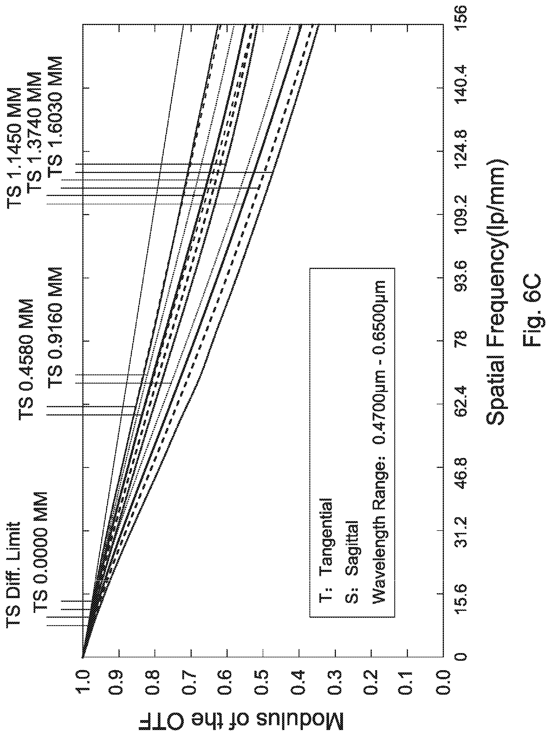
D00013
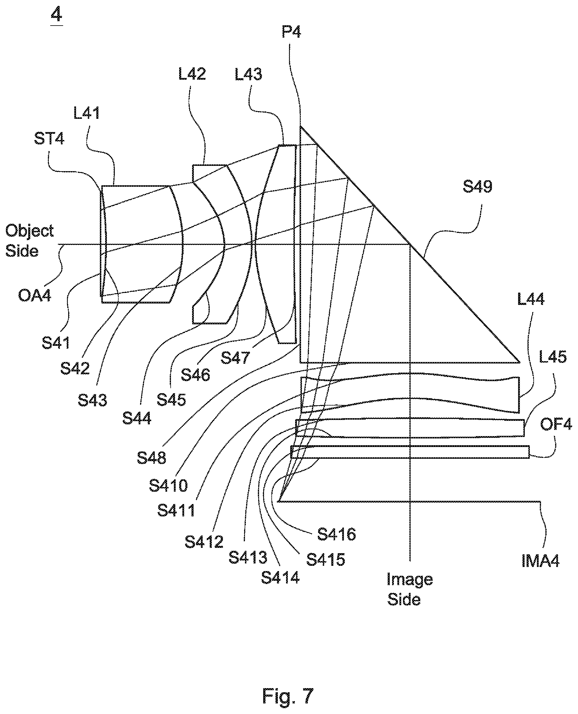
D00014

D00015

D00016

D00017

D00018

D00019
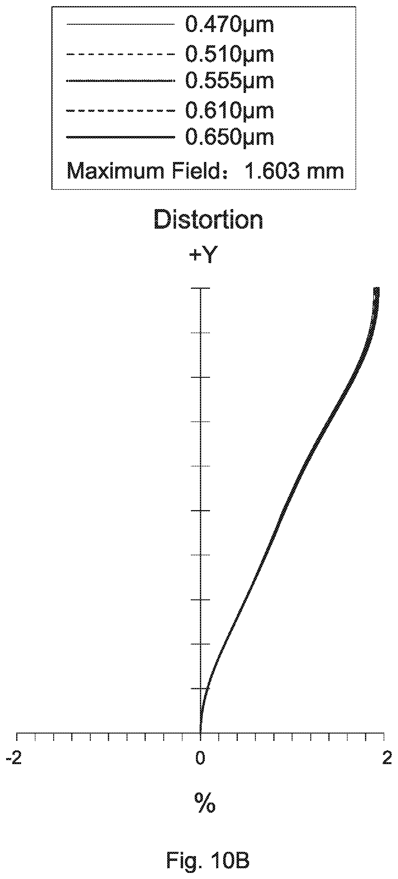
D00020

D00021

D00022
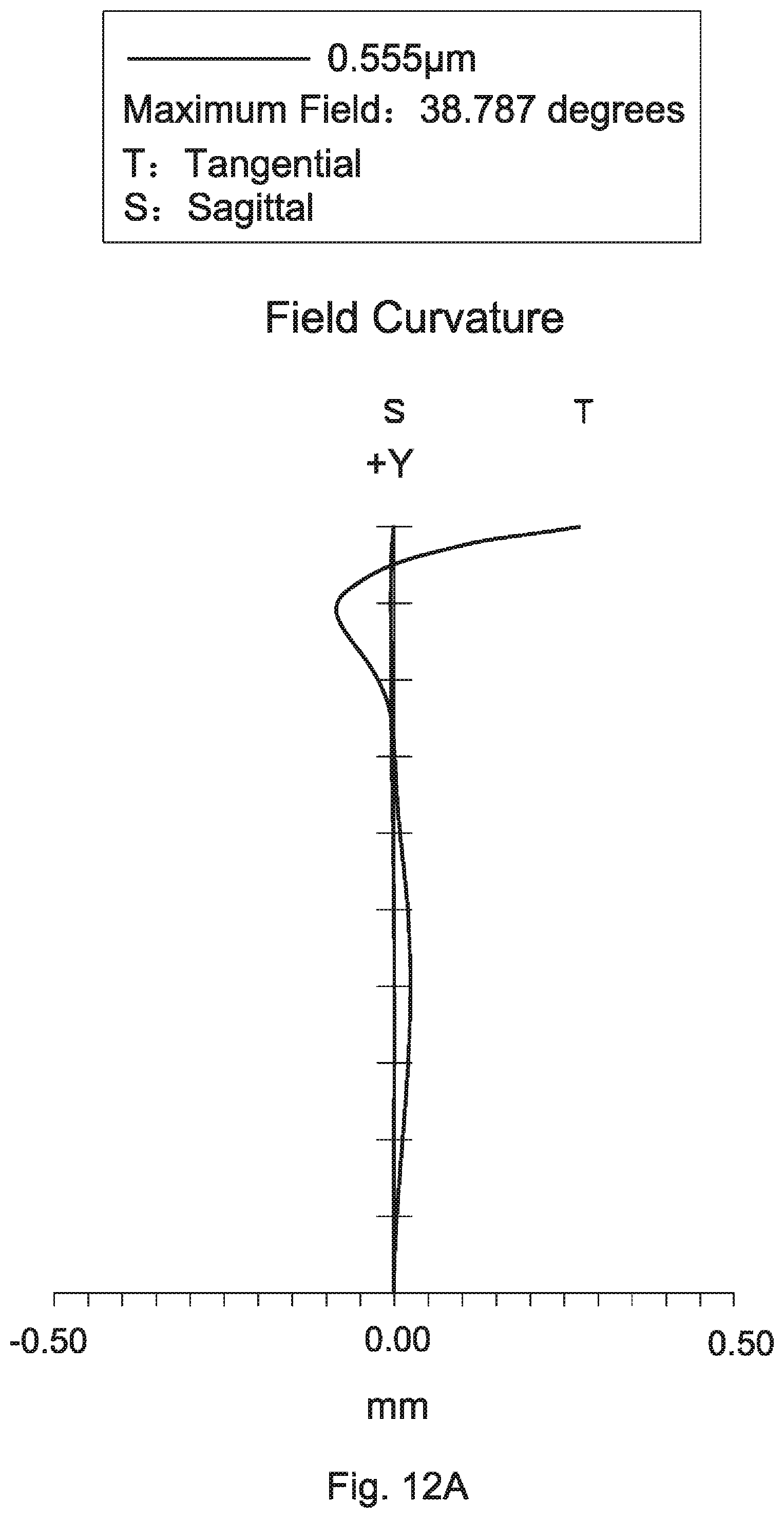
D00023

D00024

D00025
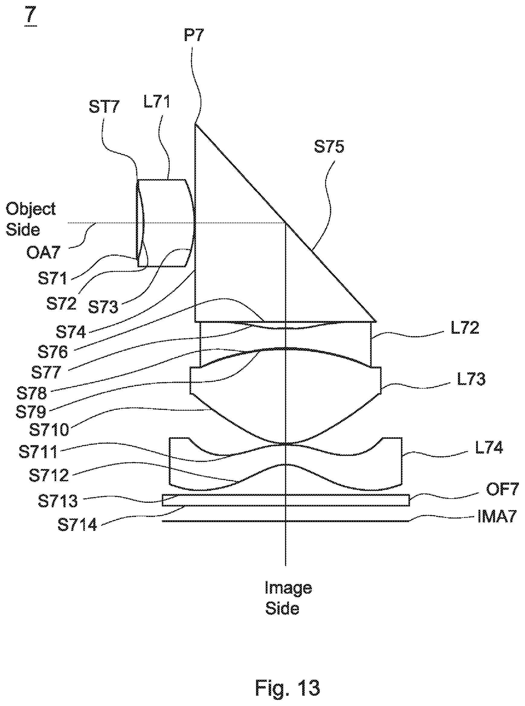
D00026
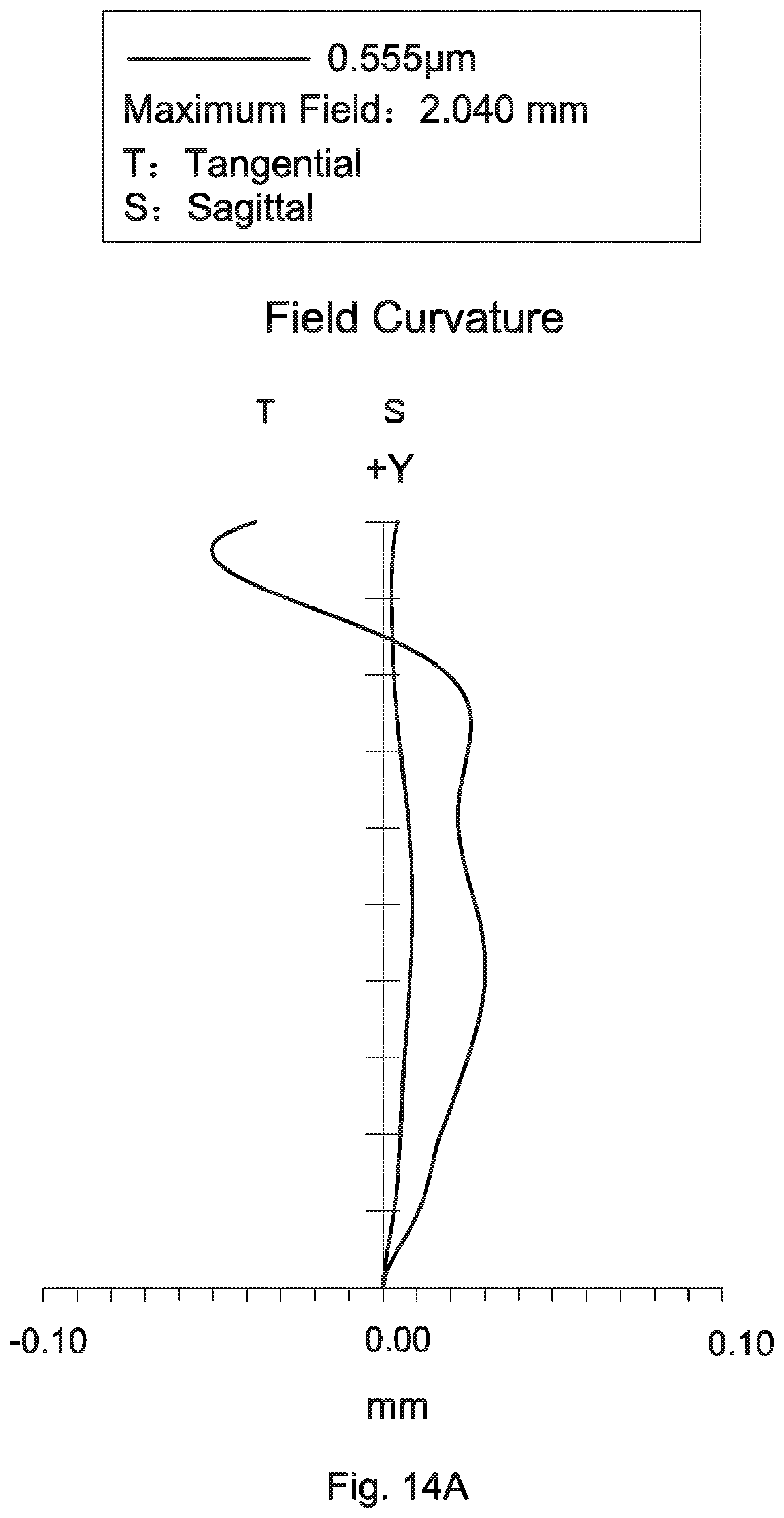
D00027

D00028
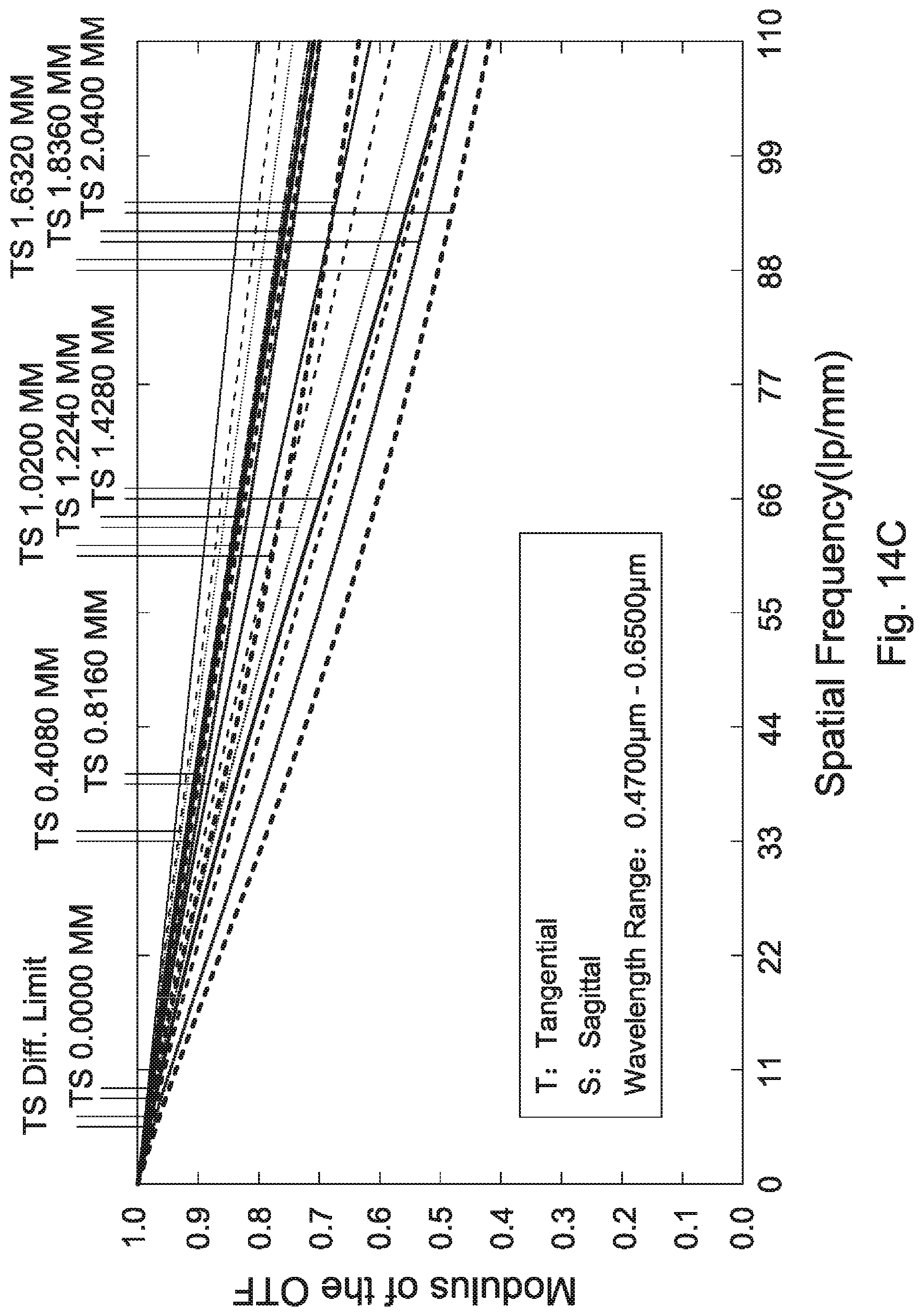
D00029
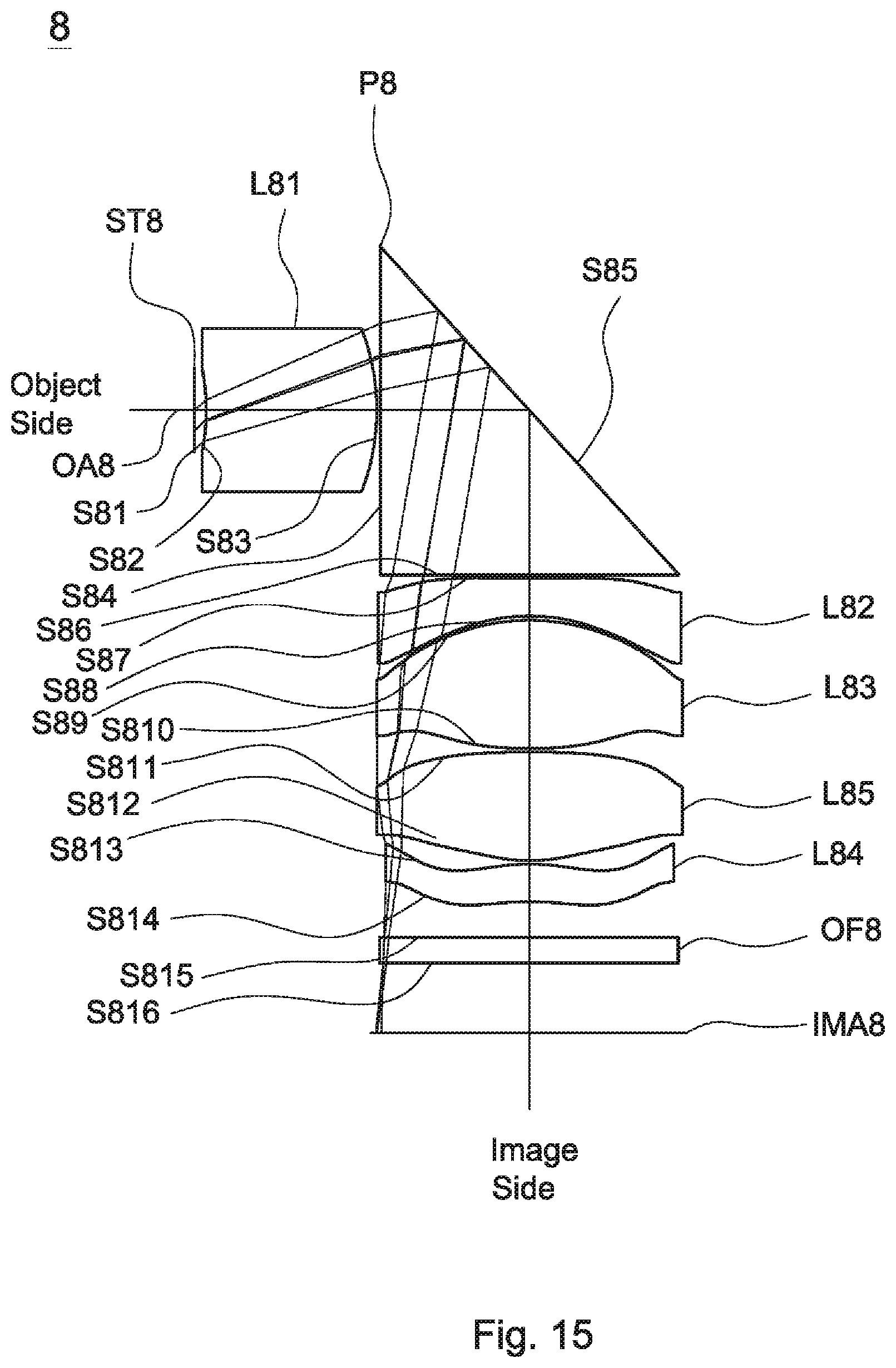
D00030

D00031
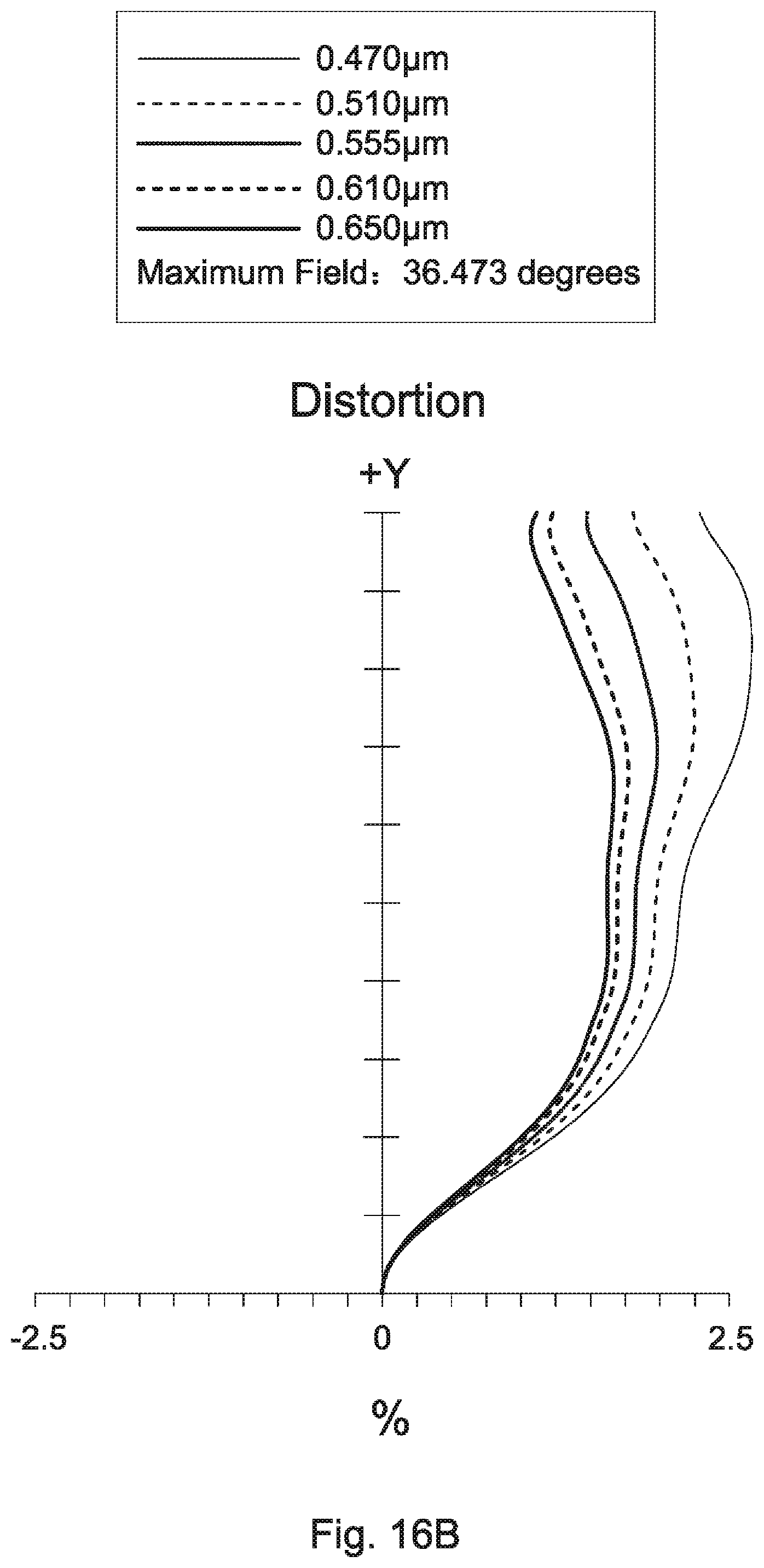
D00032
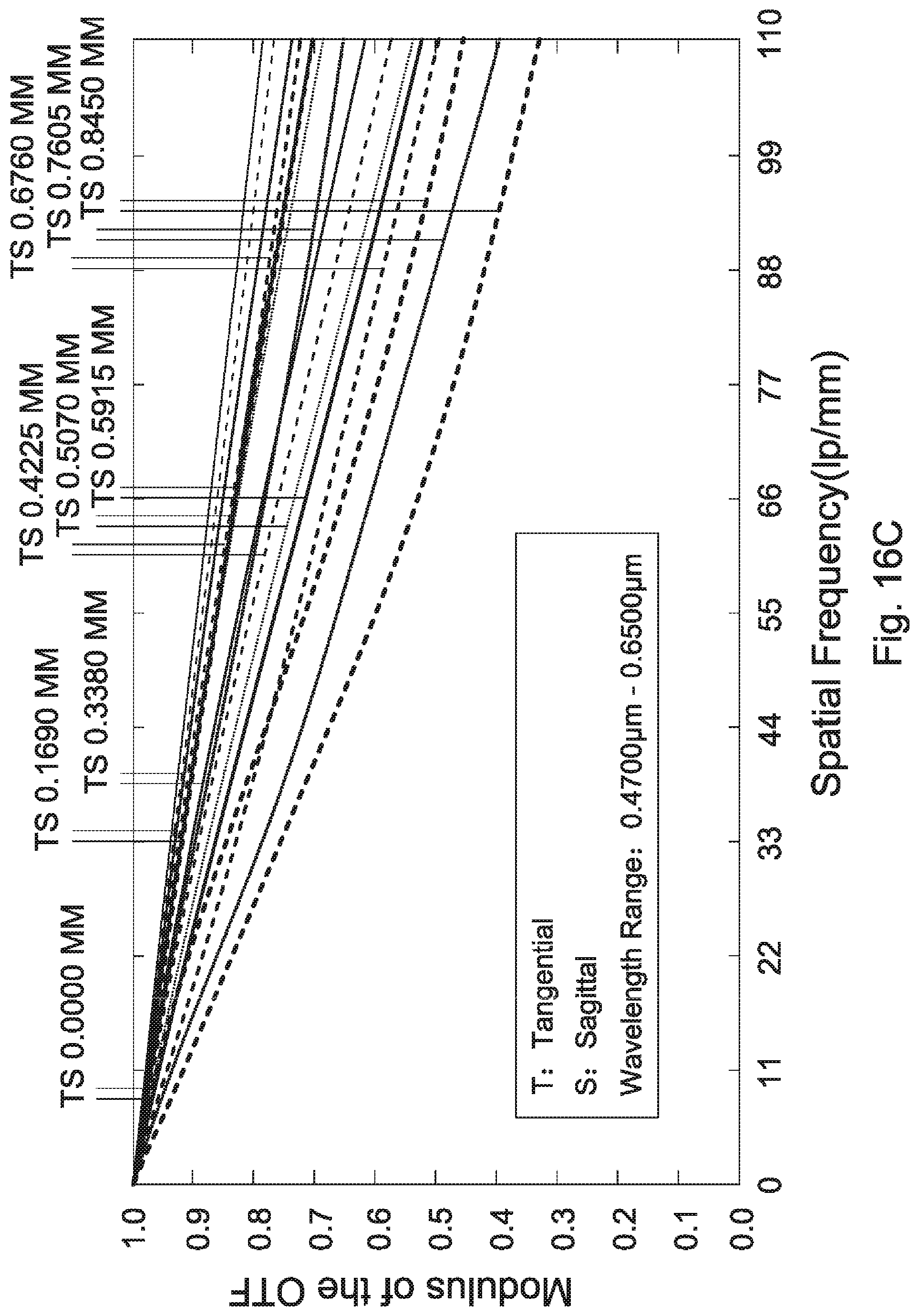
D00033
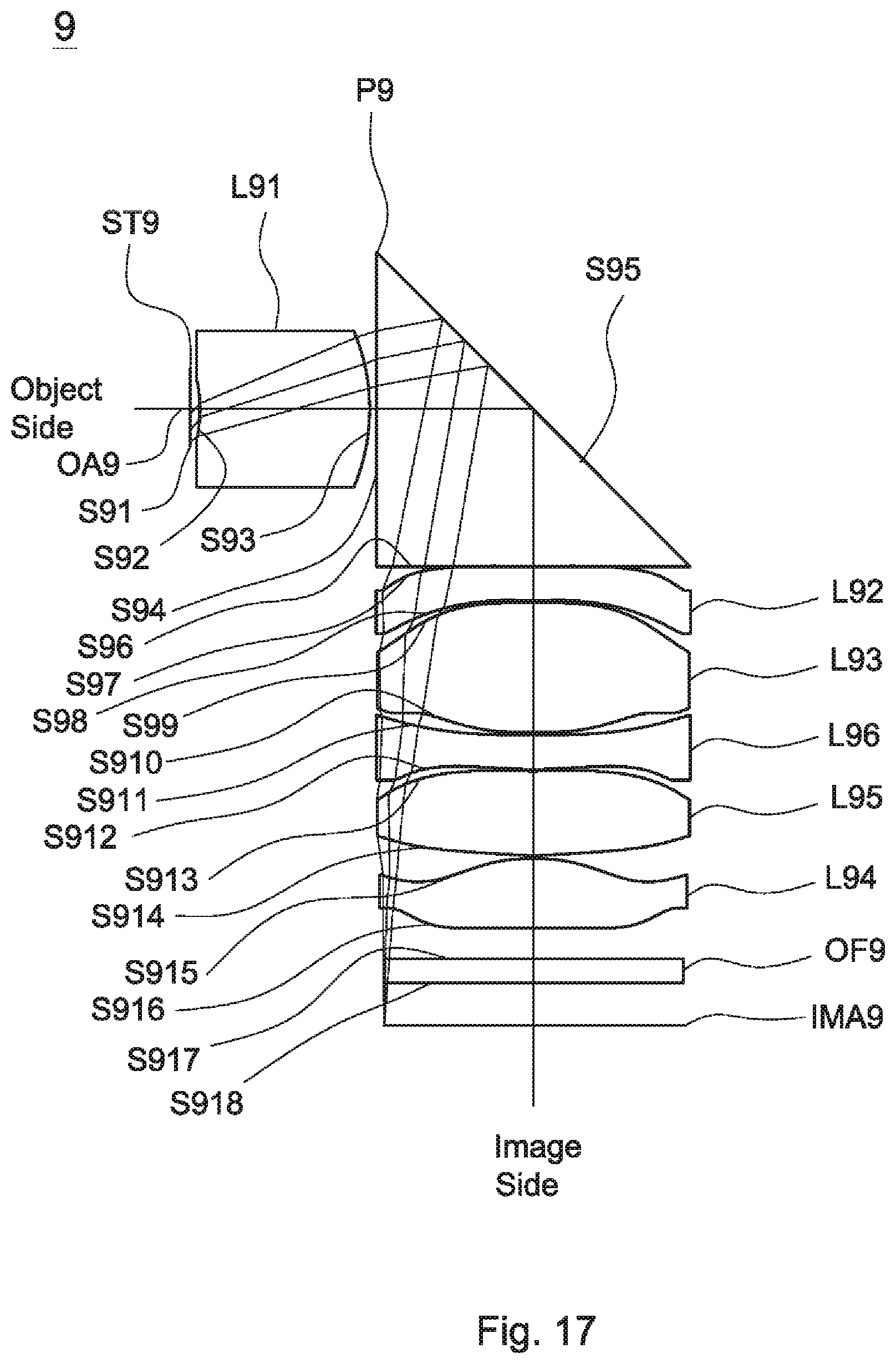
D00034
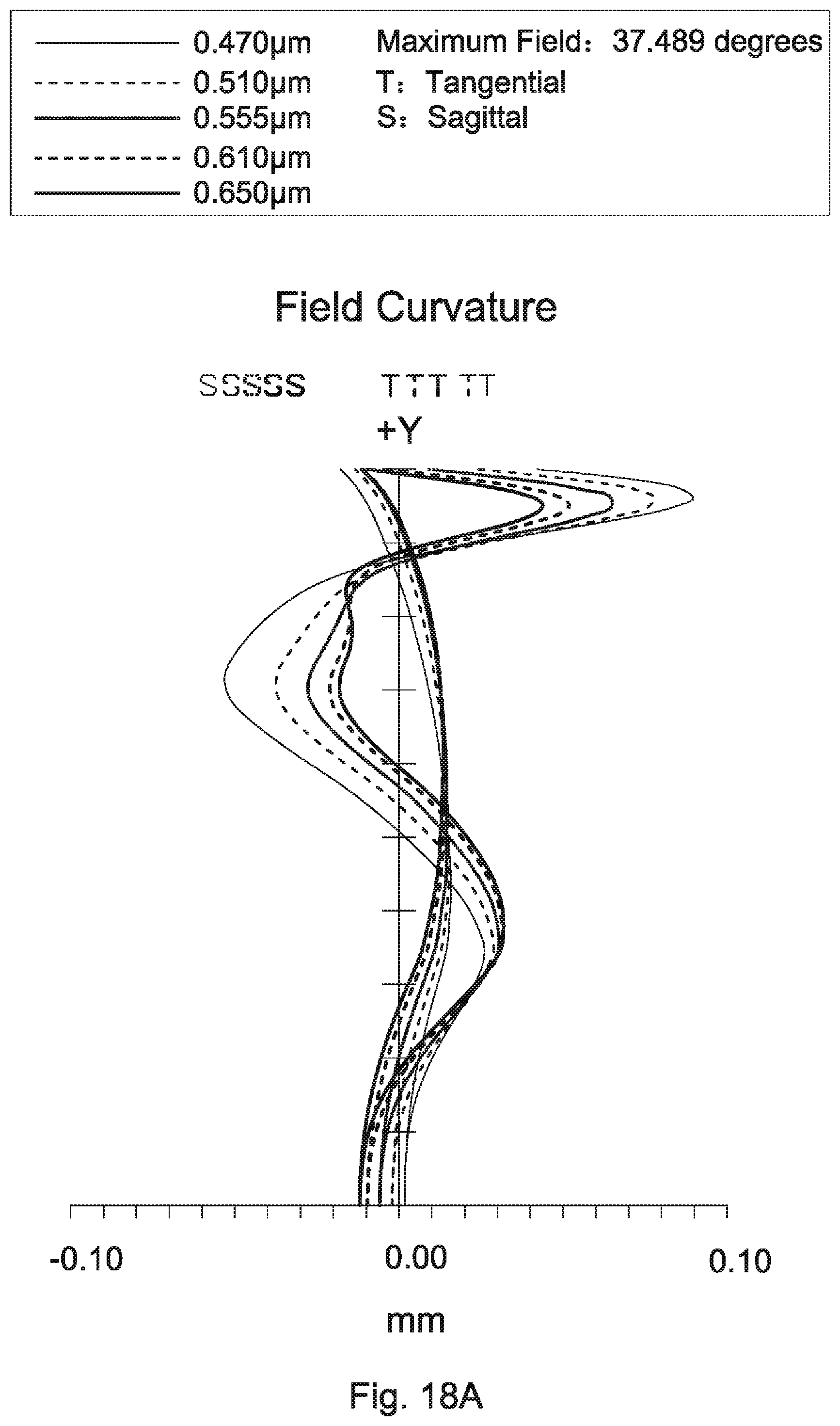
D00035

D00036
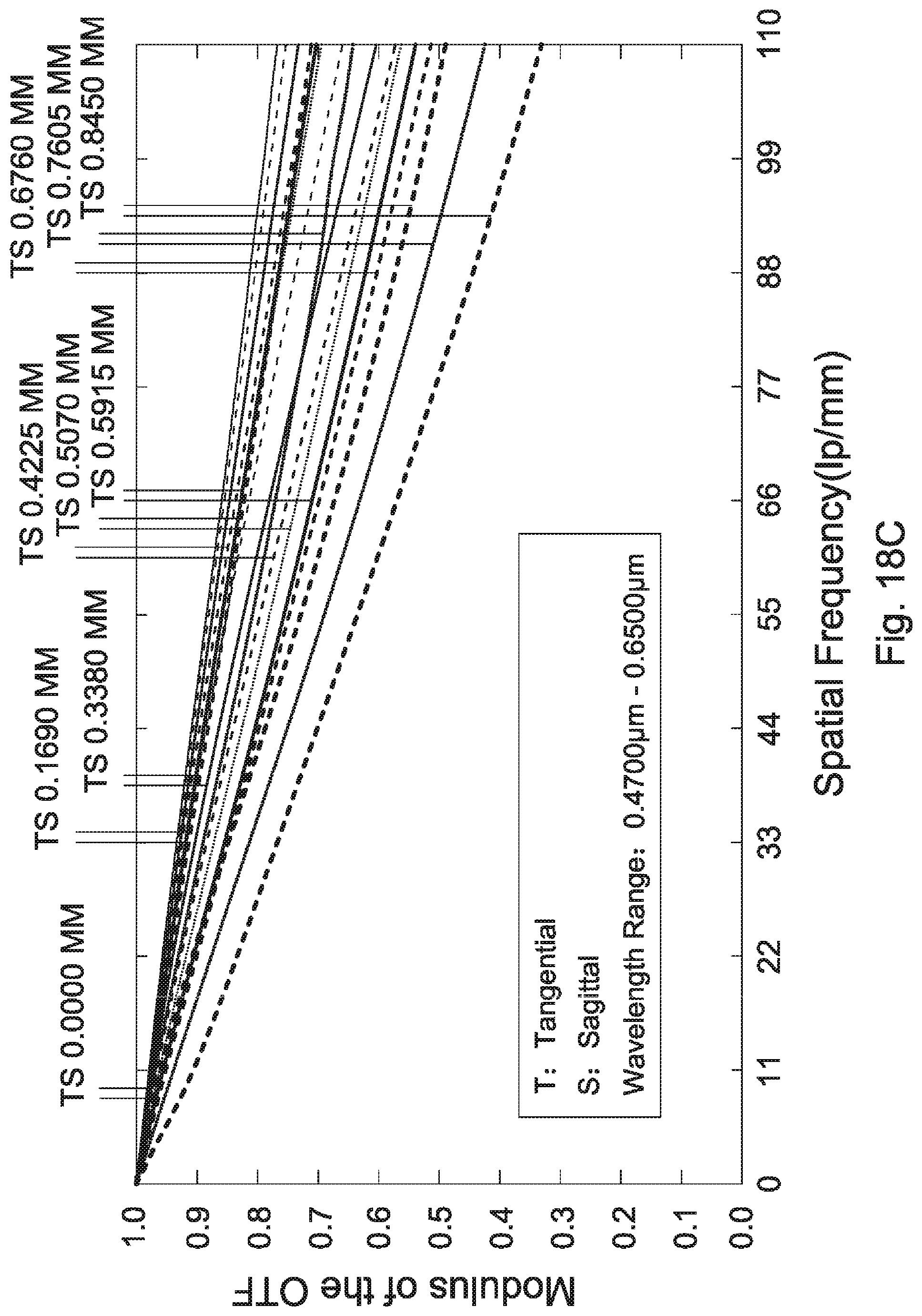
D00037
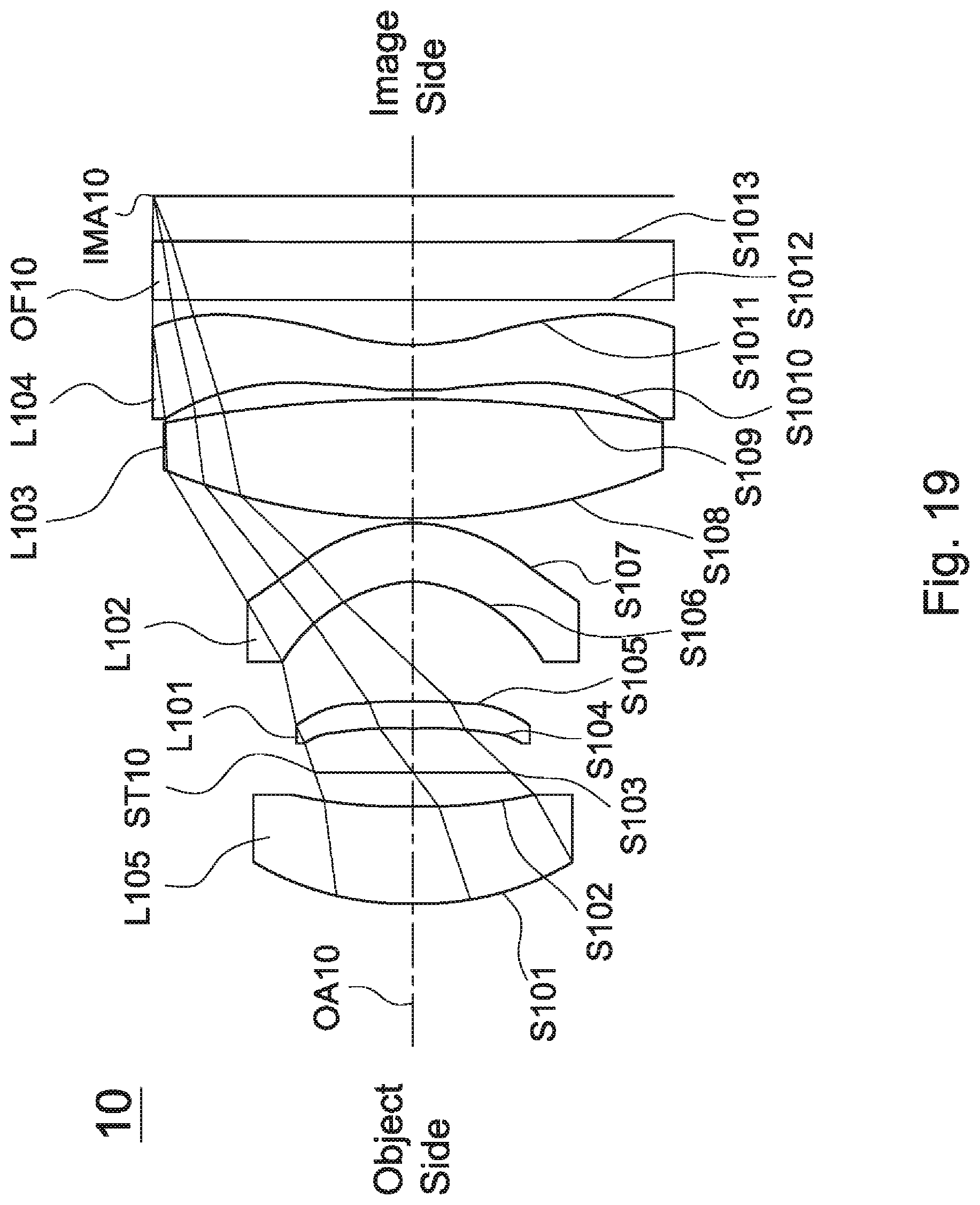
D00038

D00039

D00040

D00041
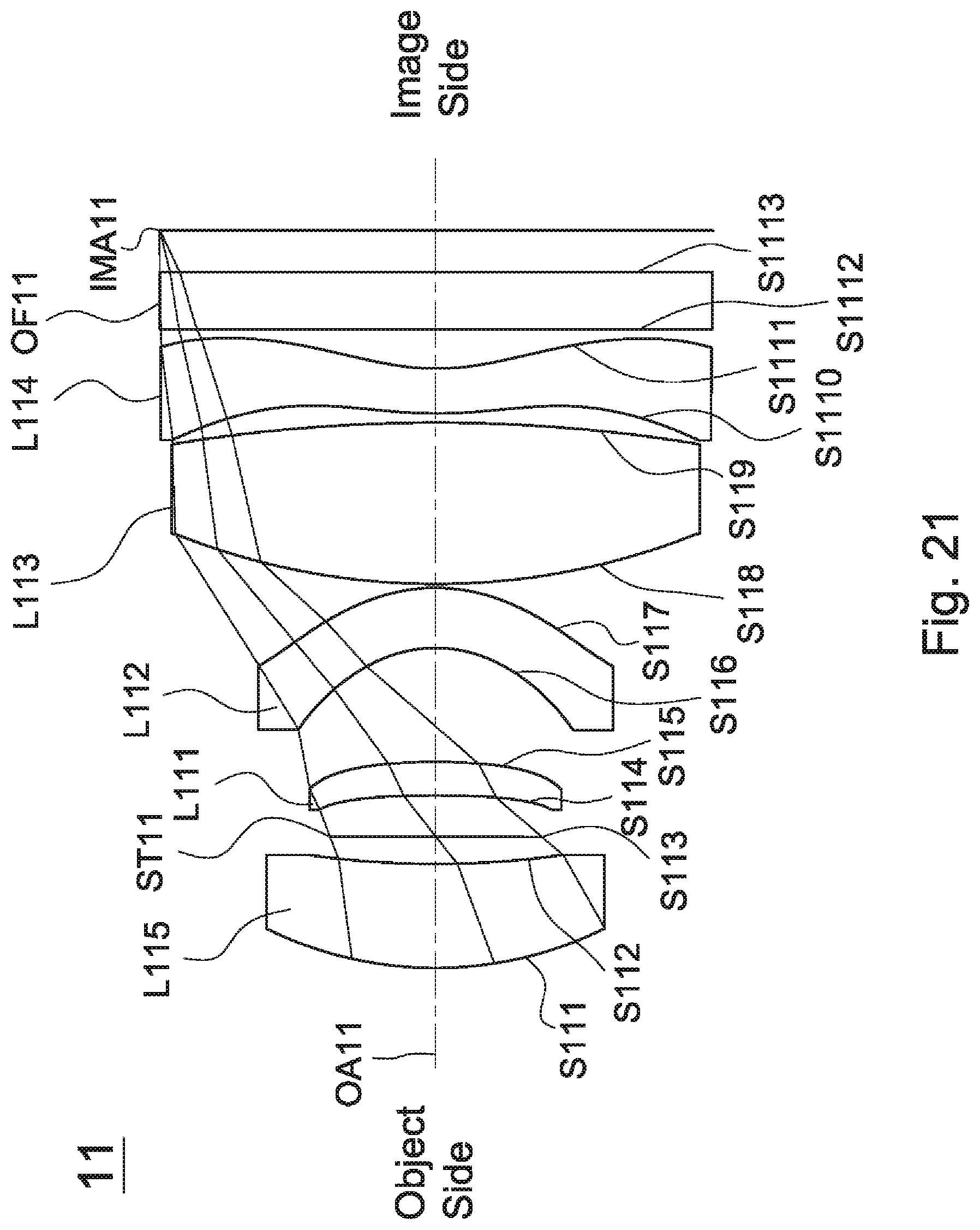
D00042

D00043
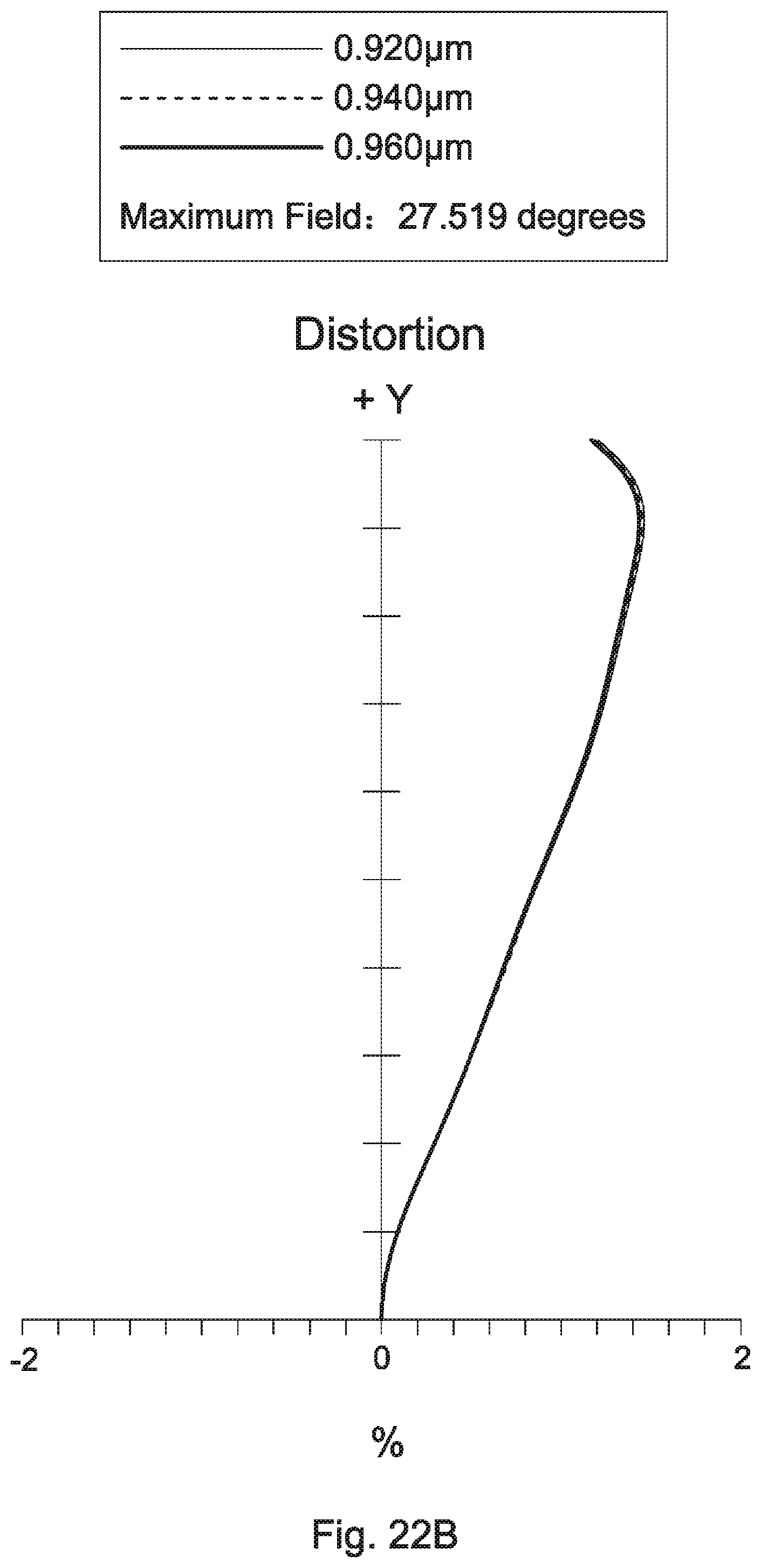
D00044

D00045

D00046
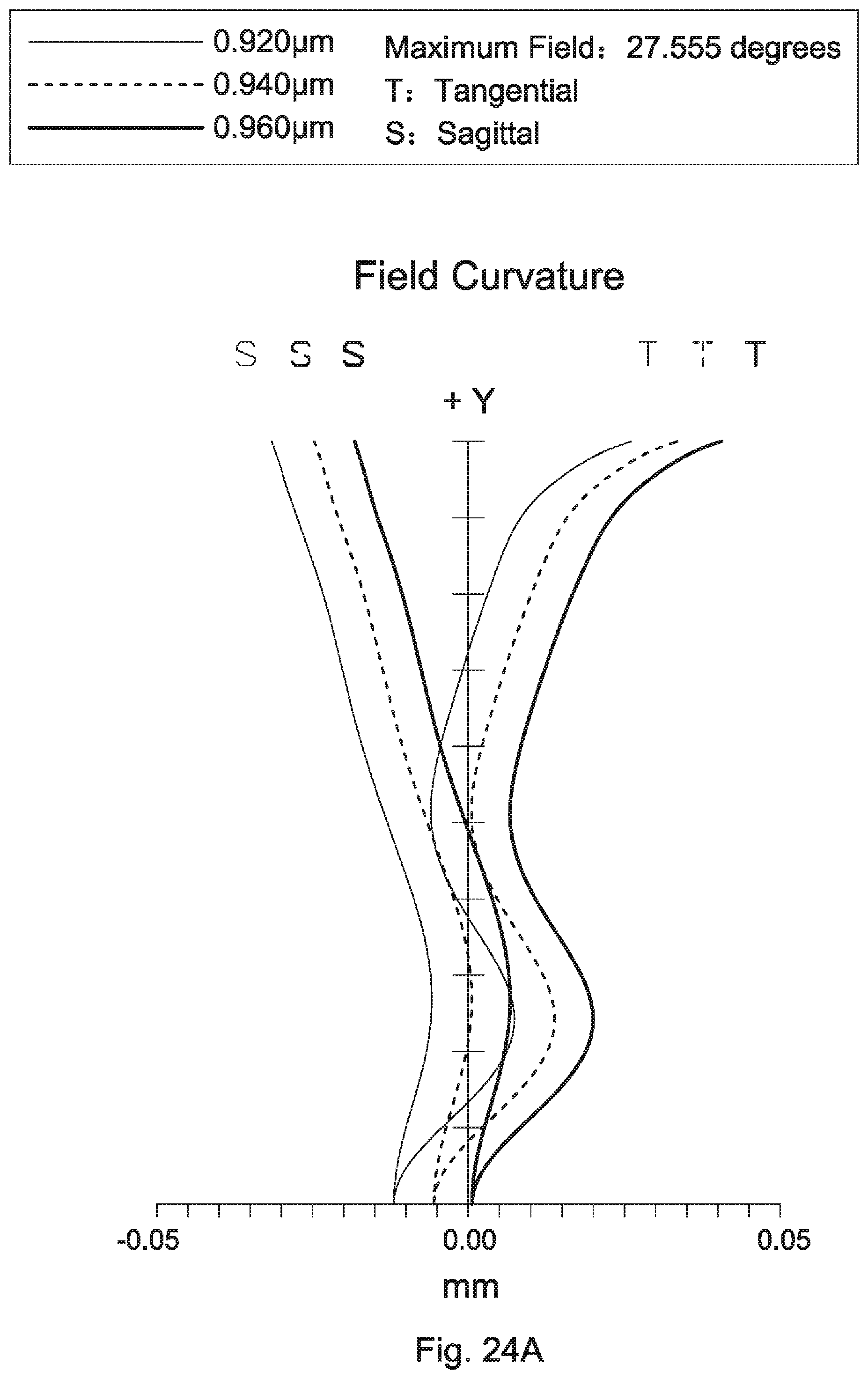
D00047
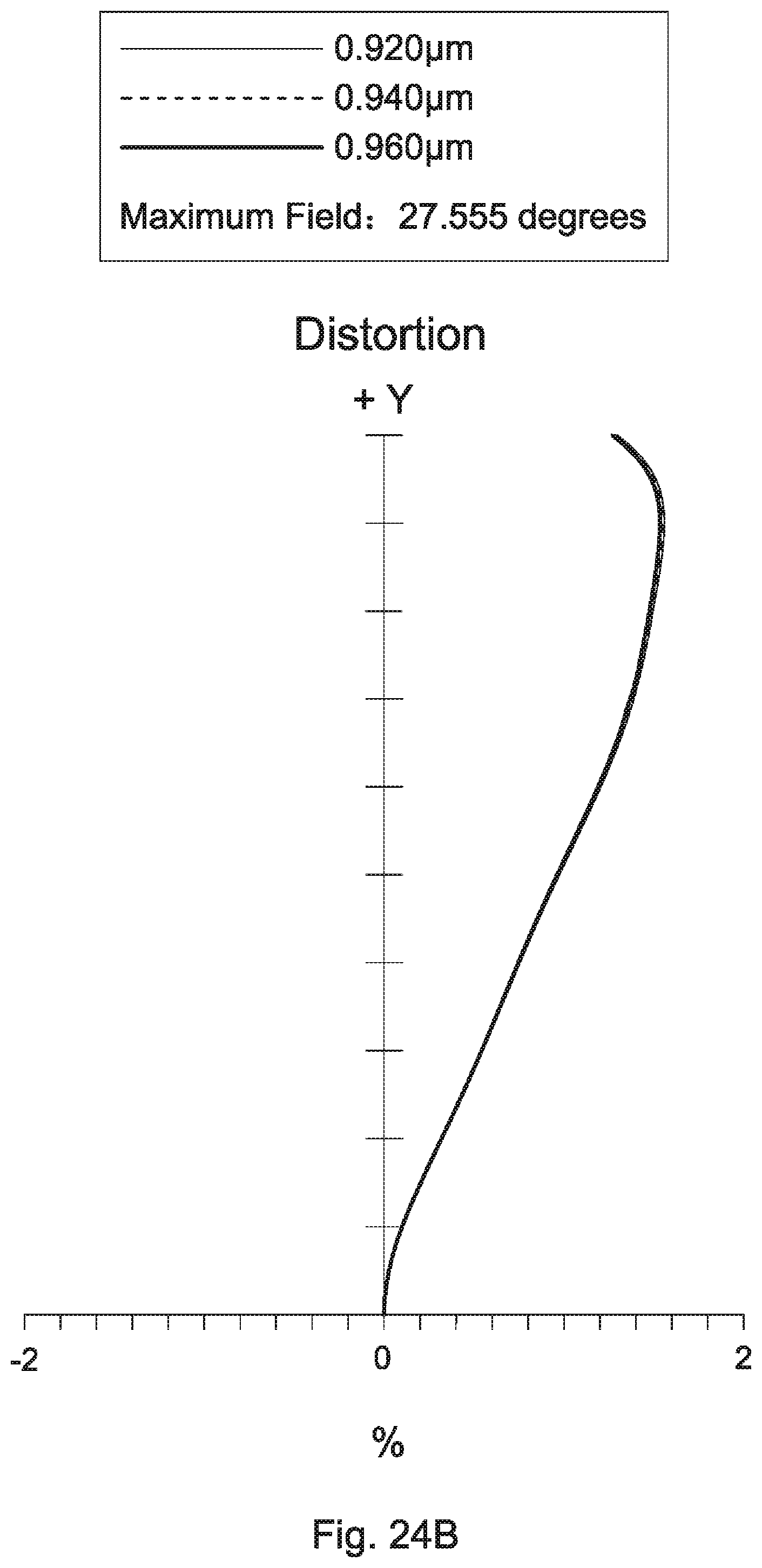
D00048
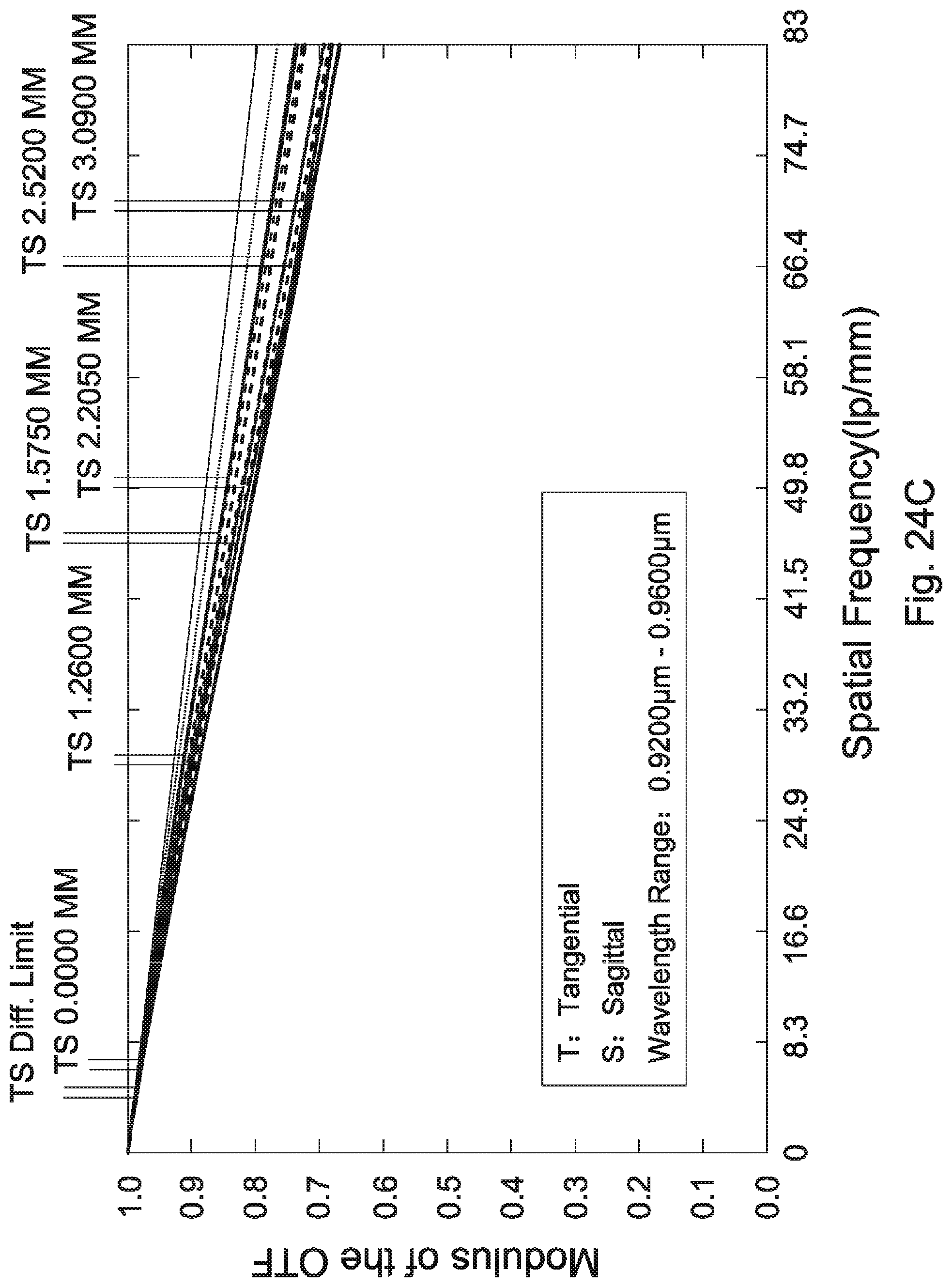
D00049
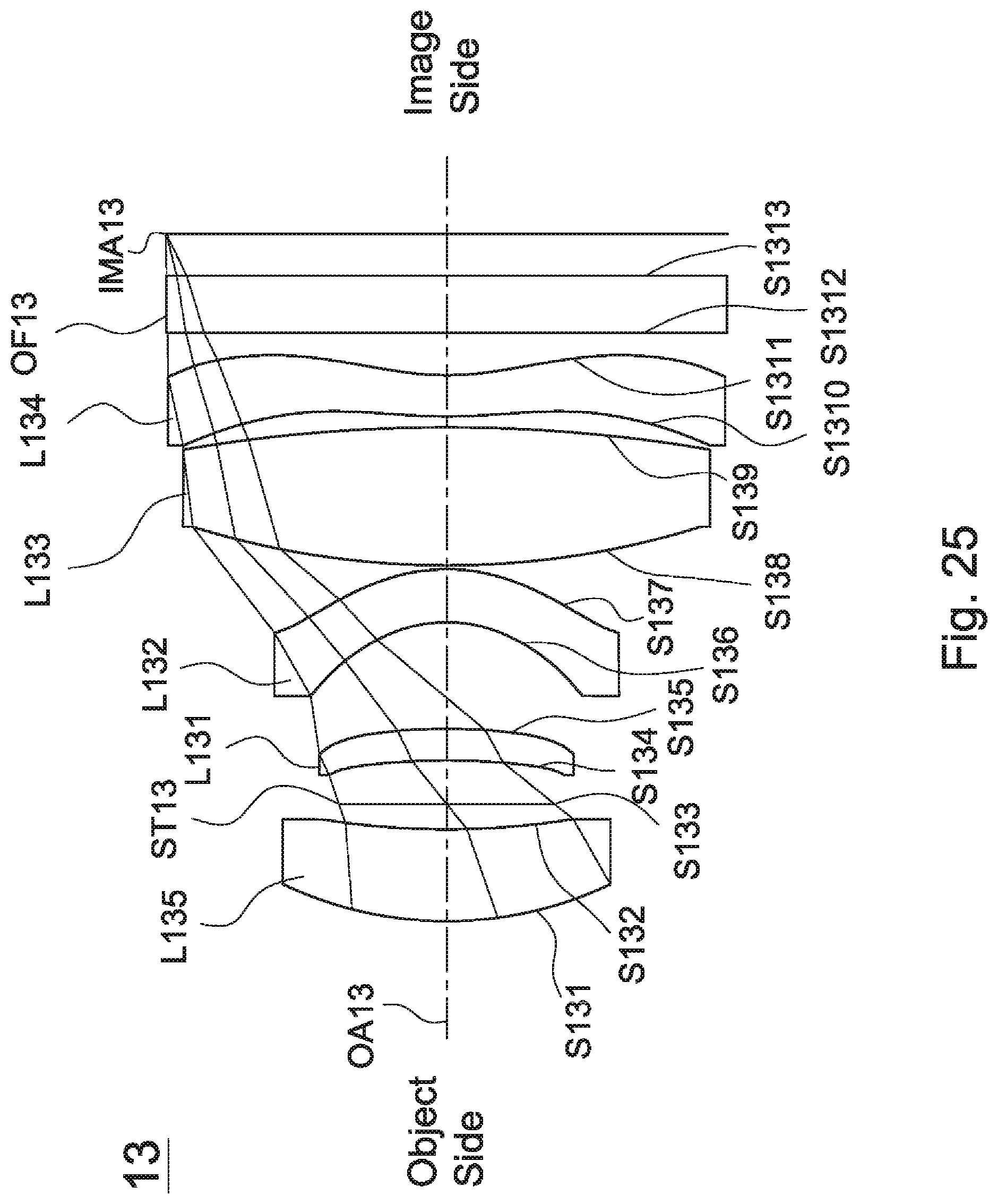
D00050

D00051

D00052
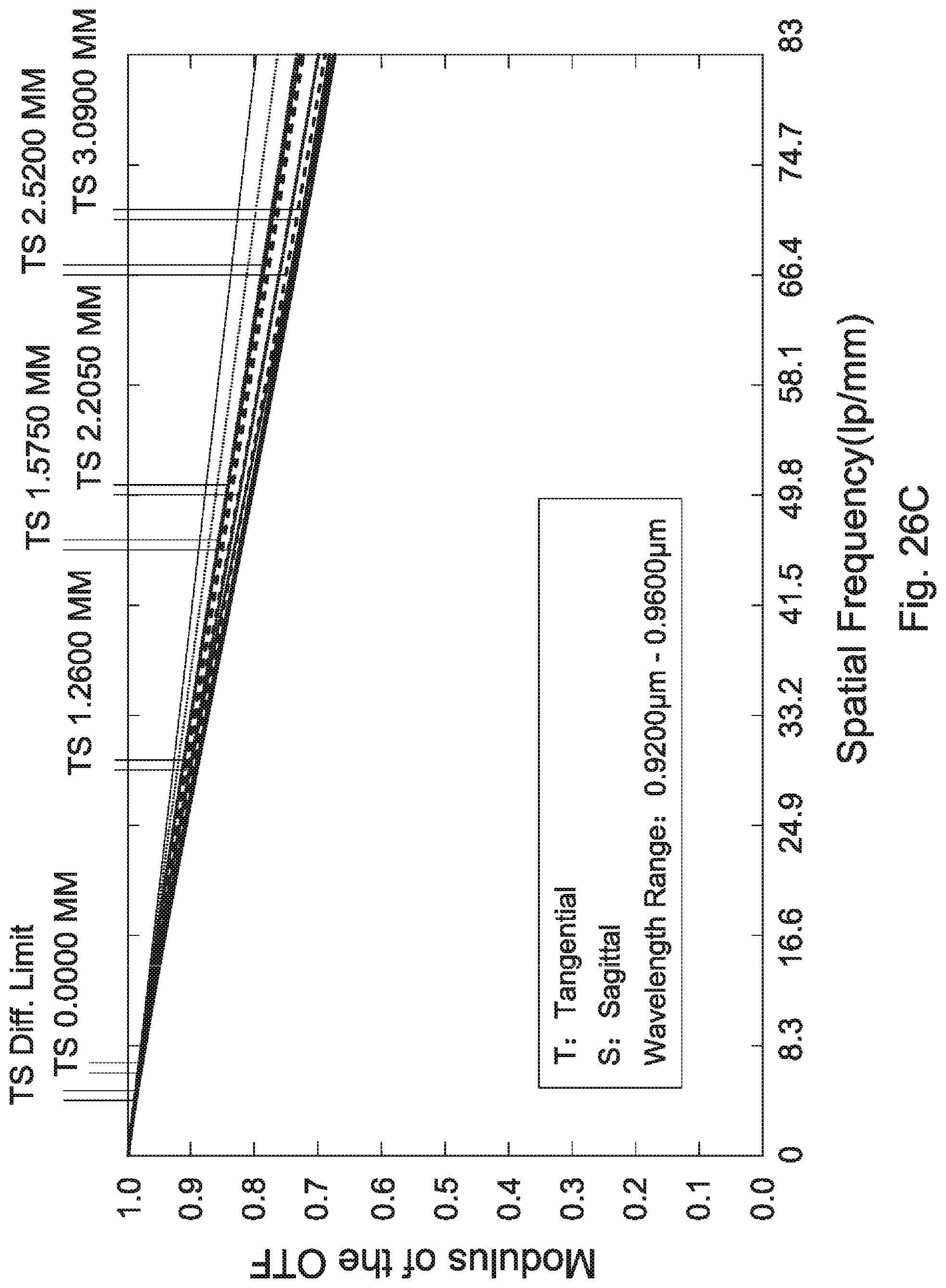
XML
uspto.report is an independent third-party trademark research tool that is not affiliated, endorsed, or sponsored by the United States Patent and Trademark Office (USPTO) or any other governmental organization. The information provided by uspto.report is based on publicly available data at the time of writing and is intended for informational purposes only.
While we strive to provide accurate and up-to-date information, we do not guarantee the accuracy, completeness, reliability, or suitability of the information displayed on this site. The use of this site is at your own risk. Any reliance you place on such information is therefore strictly at your own risk.
All official trademark data, including owner information, should be verified by visiting the official USPTO website at www.uspto.gov. This site is not intended to replace professional legal advice and should not be used as a substitute for consulting with a legal professional who is knowledgeable about trademark law.