System For Testing Under Controlled Emulated Atmospheric Conditions
Sanyal; Subrata ; et al.
U.S. patent application number 16/839254 was filed with the patent office on 2021-04-01 for system for testing under controlled emulated atmospheric conditions. This patent application is currently assigned to The United States of America, as represented by the Secretary of the Navy. The applicant listed for this patent is The United States of America, as represented by the Secretary of the Navy, The United States of America, as represented by the Secretary of the Navy. Invention is credited to Joseph A. Fiordilino, Subrata Sanyal.
| Application Number | 20210096021 16/839254 |
| Document ID | / |
| Family ID | 1000005313629 |
| Filed Date | 2021-04-01 |


| United States Patent Application | 20210096021 |
| Kind Code | A1 |
| Sanyal; Subrata ; et al. | April 1, 2021 |
System For Testing Under Controlled Emulated Atmospheric Conditions
Abstract
Exemplary embodiments include at least one modular container that can be assembled to emulate a desired atmosphere. Each container includes apertures on opposing ends of the container to allow EMR to enter and exit the container. Each container can include temperature control systems, humidity control systems, fan arrays to emulate wind/turbulence, and a plurality of sensors to measure the current conditions within the container, all of which can be installed within the containers walls.
| Inventors: | Sanyal; Subrata; (Eastvale, CA) ; Fiordilino; Joseph A.; (Corona, CA) | ||||||||||
| Applicant: |
|
||||||||||
|---|---|---|---|---|---|---|---|---|---|---|---|
| Assignee: | The United States of America, as
represented by the Secretary of the Navy Arlington VA |
||||||||||
| Family ID: | 1000005313629 | ||||||||||
| Appl. No.: | 16/839254 | ||||||||||
| Filed: | April 3, 2020 |
Related U.S. Patent Documents
| Application Number | Filing Date | Patent Number | ||
|---|---|---|---|---|
| 62829855 | Apr 5, 2019 | |||
| Current U.S. Class: | 1/1 |
| Current CPC Class: | G01J 1/0252 20130101; G01T 7/00 20130101 |
| International Class: | G01J 1/02 20060101 G01J001/02; G01T 7/00 20060101 G01T007/00 |
Goverment Interests
STATEMENT REGARDING FEDERALLY SPONSORED RESEARCH OR DEVELOPMENT
[0002] The invention described herein was made in the performance of official duties by employees of the Department of the Navy and may be manufactured, used and licensed by or for the United States Government for any governmental purpose without payment of any royalties thereon. This invention (Navy Case 200,623) is assigned to the United States Government and is available for licensing for commercial purposes. Licensing and technical inquiries may be directed to the Technology Transfer Office, Naval Surface Warfare Center, Corona Division, email: CRNA_CTO@navy.mil.
Claims
1. A system for testing under controlled emulated atmospheric conditions comprising: at least one fan, at least one heating element, at least one cooling element, at least one pump, and a container comprising six walls, wherein the container forms an interior cavity, the container further comprising aligned first and second apertures on first and second opposing walls of the six walls which open into the interior cavity.
2. The system of claim 1, further comprising a humidifier and a pump.
3. The system of claim 2, wherein the humidifier and the pump are coupled to third and fourth opposing walls of the six walls, respectively.
4. The system of claim 2, further comprising at least one temperature sensor, at least one humidity sensor, at least one wind sensor, and at least one pressure sensor.
5. The system of claim 2, further comprising an electromagnetic radiation source aligned such that electromagnetic radiation emitted by the radiation source enters the first aperture and exits the second aperture.
6. A system for testing under controlled emulated atmospheric conditions comprising: a first container comprising first six walls forming a first interior cavity and first and second apertures on first and second opposing walls of the first six walls which open into the first interior cavity; a plurality of peripherals adapted to couple to the first six walls, wherein the plurality of peripherals are configured to adjust the temperature, pressure, and humidity within the first container.
7. The system of claim 6, wherein each wall of the first six walls comprises an opening section such that retracting or removing the opening section creates an opening between the inside and outside of the first container.
8. The system of claim 7, further comprising a second container comprising second six walls forming a second interior cavity, wherein each wall of the second six walls comprises an opening section such that retracting or removing the opening section creates an opening between the inside and outside of the second container, wherein each wall of the first six walls is configured to couple to a corresponding wall of the second six walls, wherein after coupling the first container to the second container, adjoining opening sections can be retracted or removing to create an opening connecting the first and second interior cavities.
9. A method of testing electromagnetic radiation (EMR) sources comprising: providing an EMR source; providing a test system comprising: a container comprising six walls, wherein the container forms an interior cavity, the container further comprising aligned first and second apertures on first and second opposing walls of the six walls which open into the interior cavity a plurality of peripherals coupled to the six walls; wherein the EMR source aligned such that EMR emitted by the radiation source enters the first aperture and exits the second aperture; modifying atmospheric conditions within the container by activating the plurality of peripherals; activating the EMR source to transmit entry EMR into the container; recording properties of exit EMR leaving the container.
Description
CROSS-REFERENCE TO RELATED APPLICATIONS
[0001] The present application claims priority to U.S. Provisional Patent Application Ser. No. 62/829,855, filed Apr. 5, 2019, entitled "System For Testing Under Controlled Emulated Atmospheric Conditions," the disclosure of which is expressly incorporated by reference herein.
FIELD OF THE INVENTION
[0003] The present invention relates to an enclosure for testing electromagnetic radiation under simulated atmospheric conditions.
BACKGROUND AND SUMMARY OF THE INVENTION
[0004] The present invention relates to an enclosure for testing electromagnetic radiation (EMR) by emulating atmospheric conditions within the enclosure.
[0005] According to an illustrative embodiment of the present disclosure, at least one modular container can be assembled to emulate a desired atmosphere. Each container includes apertures on opposing ends of the container to allow EMR to enter and exit the container. Each container can include temperature control systems (e.g., a hot plate, a hot wire, a cold plate, etc.), humidity control systems (e.g., a humidifier, a dehumidifier), fan arrays to emulate wind/turbulence, and a plurality of sensors to measure the current conditions within the container. These control systems allows for variation of different measurement parameters (e.g., temperature, humidity, wind-speed, etc.) independently or in any combination of these to achieve different statistically steady atmospheric conditions inside the container.
[0006] According to a further illustrative embodiment of the present disclosure, containers can be aligned to combine the containers linearly (e.g., to test across longer distances) or stacked to combine containers vertically/horizontally (e.g., to allow more complex atmospheric conditions). The walls of these containers could be made of collapsible shutters for the ease of open/close control. Once a desired statistically steady atmospheric condition is reached in each of the stacked containers, the shutters in between them could be opened to emulate the condition in longer distances or larger volumes.
[0007] Additional features and advantages of the present invention will become apparent to those skilled in the art upon consideration of the following detailed description of the illustrative embodiment exemplifying the best mode of carrying out the invention as presently perceived.
BRIEF DESCRIPTION OF THE DRAWINGS
[0008] The detailed description of the drawings particularly refers to the accompanying figures in which:
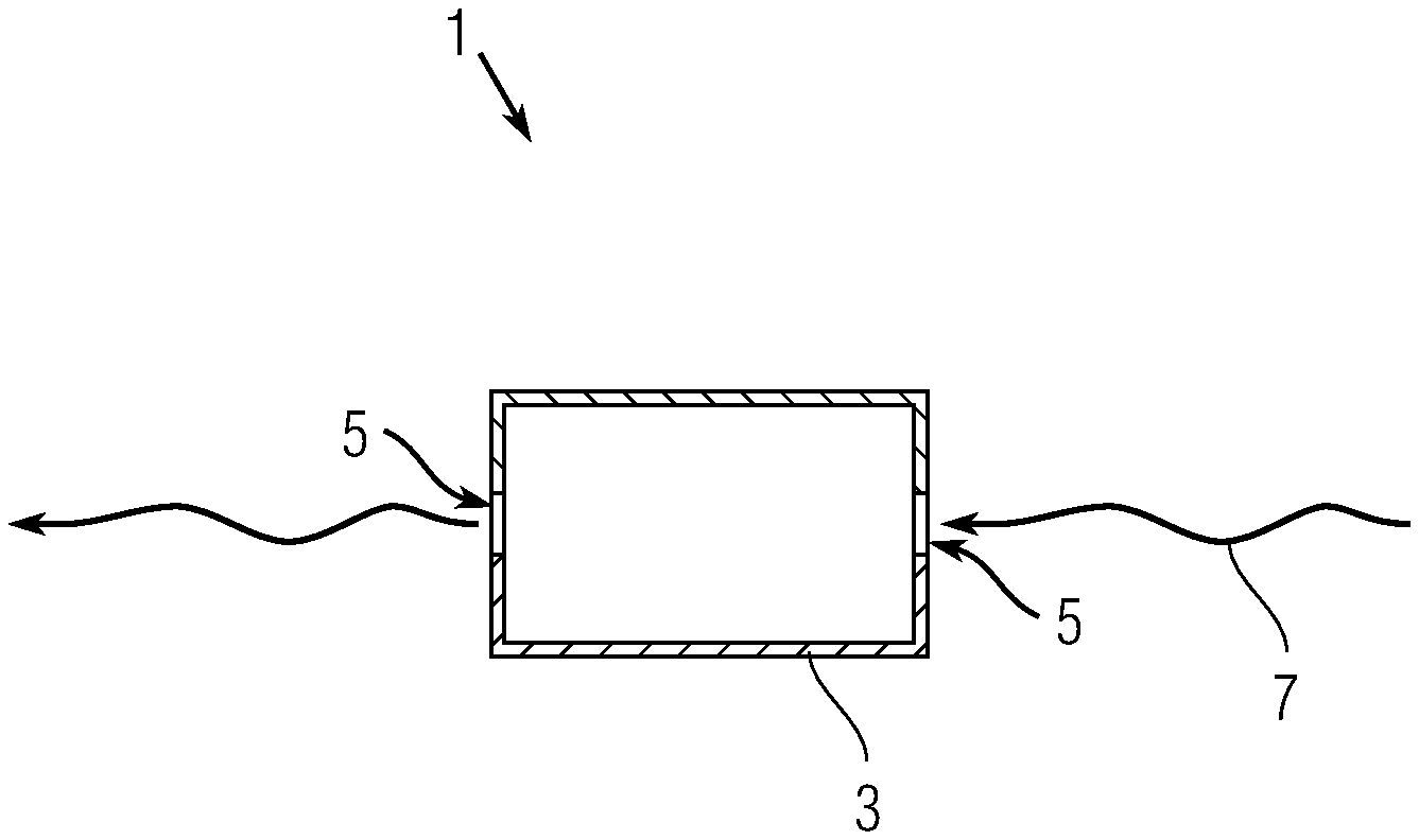
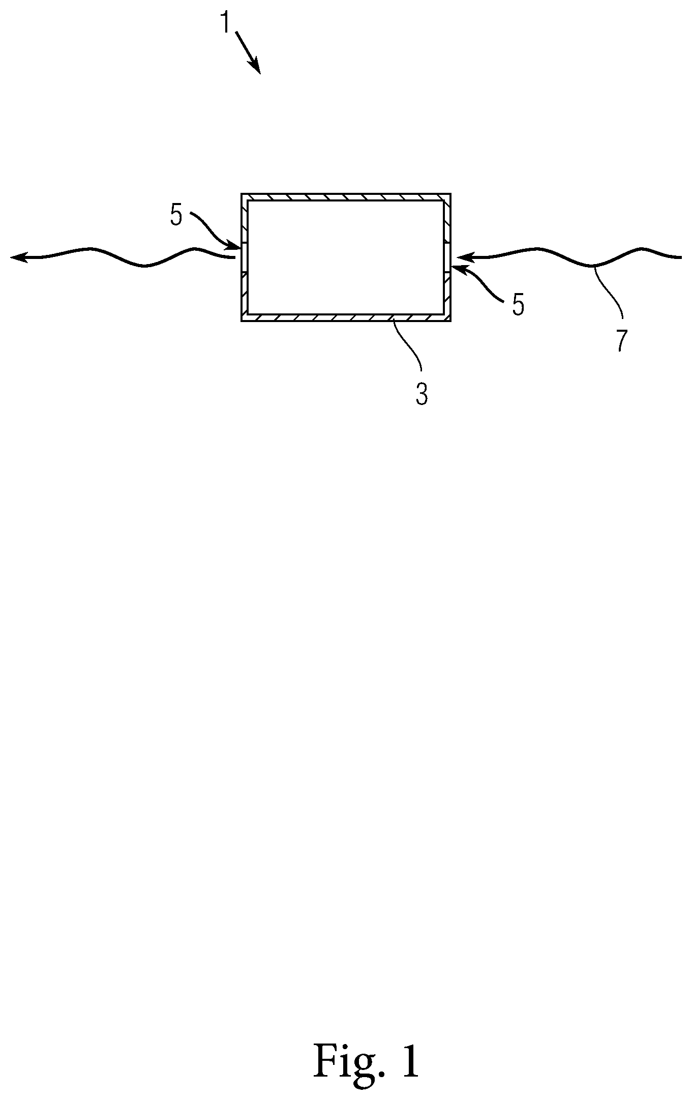
[0009] FIG. 1 shows an exemplary emulation system.
[0010] FIG. 2 shows a block diagram of the components of an exemplary emulation system.
[0011] FIGS. 3A-B show additional views of an exemplary container with a heating element.
[0012] FIG. 4 shows a top section of an exemplary container.
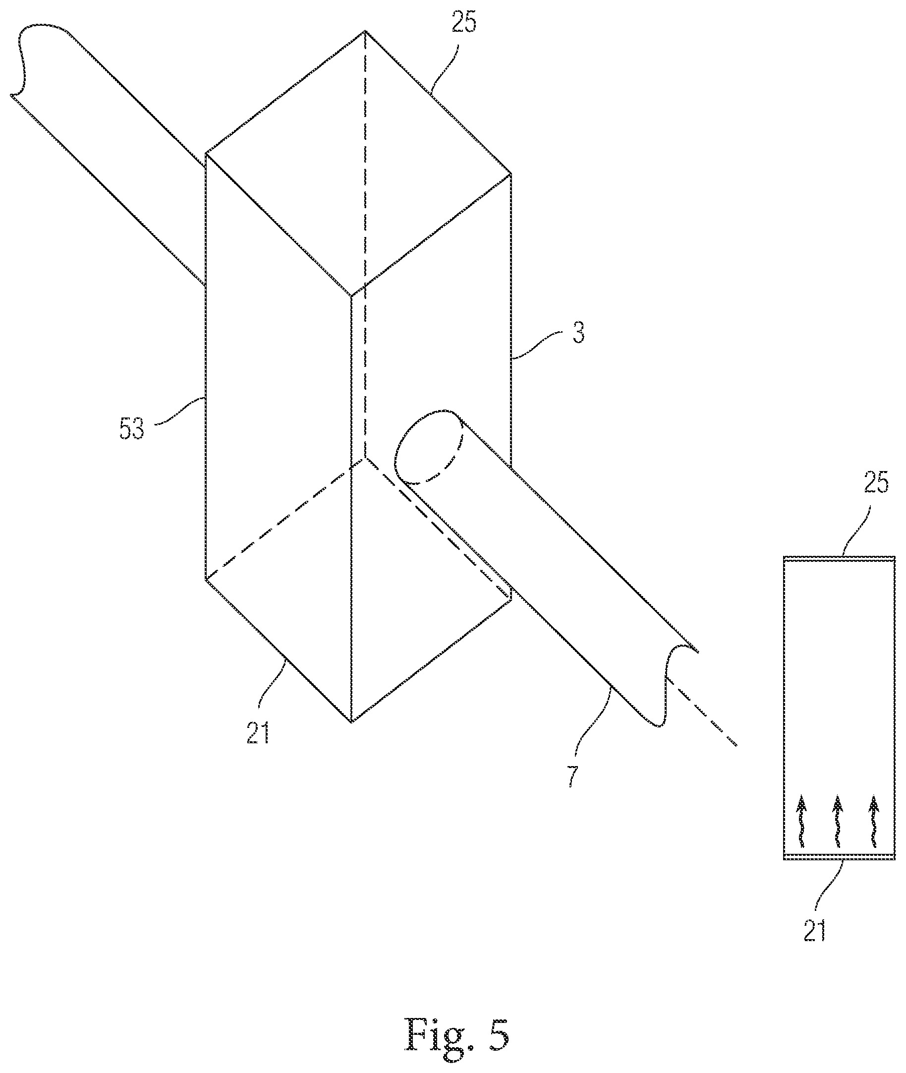
[0013] FIG. 5 shows an isometric view of an exemplary container.
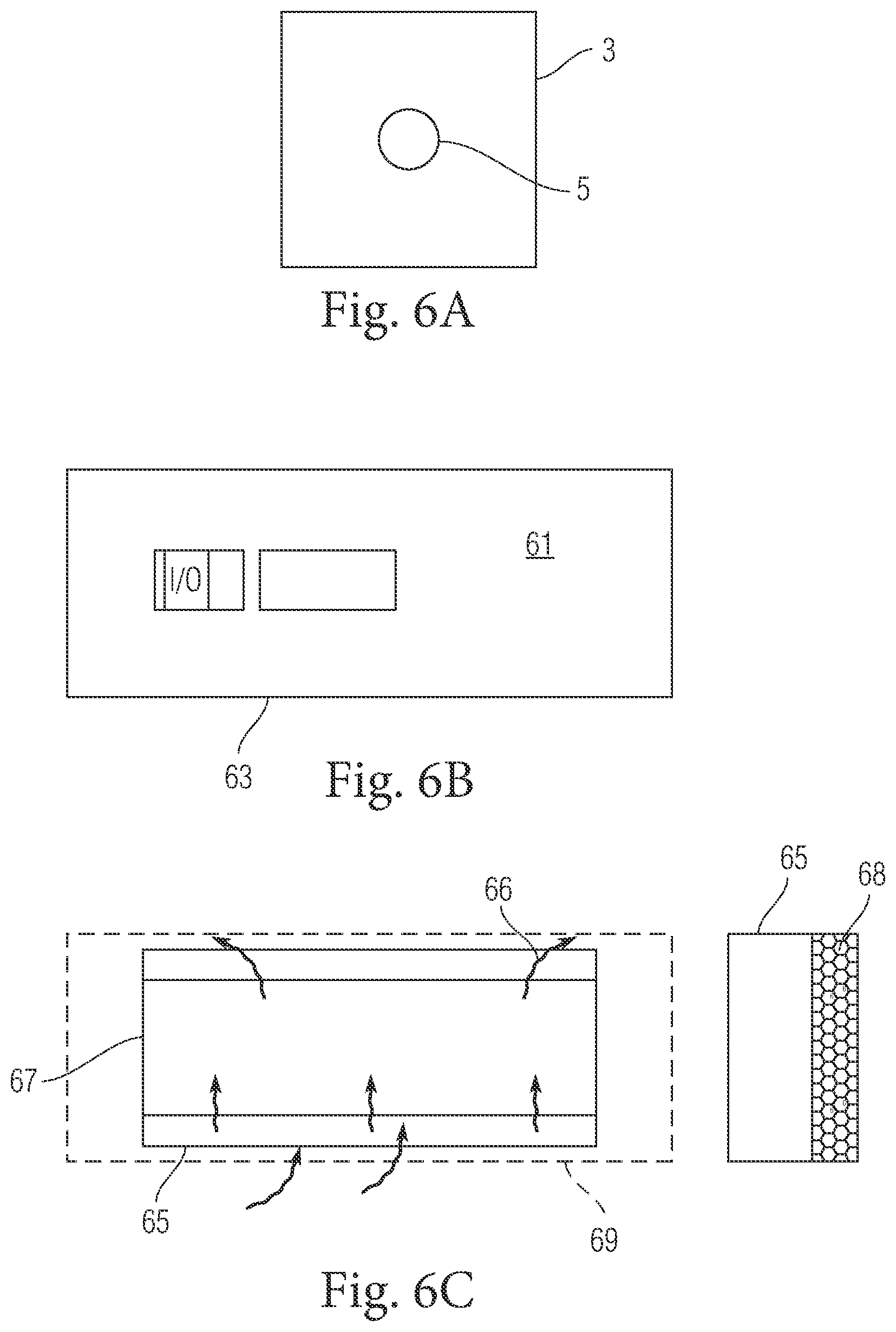
[0014] FIG. 6A-C shows exterior views of an exemplary container.
[0015] FIGS. 7A-C show a cross sectional views of an exemplary container.
[0016] FIG. 8 shows exemplary emulation systems with connected containers.
DETAILED DESCRIPTION OF THE DRAWINGS
[0017] The embodiments of the invention described herein are not intended to be exhaustive or to limit the invention to precise forms disclosed. Rather, the embodiments selected for description have been chosen to enable one skilled in the art to practice the invention.
[0018] FIG. 1 shows an exemplary emulation system 1 having an emulation container 3. Container 3 has two apertures 5 on opposing sides of the container. An EMR beam 7 can be propagated through the container by entering a first aperture and exiting a second aperture. EMR power, beam quality, beam profile, etc. can be measured, and the resulting data can be utilized to test models and create new models. Because longer optical paths provide better analysis of EMR beams, each container 3 is generally longer (e.g., from aperture to aperture) than wide or tall.
[0019] FIG. 2 shows a block diagram of the components of an exemplary emulation system. A plurality of peripheral systems can be coupled to the walls of container 3 to enable a variety of functions or precision control. Peripheral systems can include a vacuum pump 23, humidity control mechanisms (e.g., humidifier 29), temperature control mechanisms (e.g., a heating element 21 and cooling element 25), and at least one fan 27.
[0020] FIGS. 3A-B show additional views of an exemplary container 3 with a heating element 21 (e.g., a wire with an electrical current 35 passing through the wire). The wind speed, temperature, pressure, and humidity can be measured by well-known measurement devices (e.g., hygrometers, sonic anemometer, etc.) traceable to known measurement standards. In exemplary embodiments, a controller can be configured to activate container peripherals until particular readings are recorded by sensors 31 (e.g., activate a heating element until a particular temperature is reached). It is generally preferable to put the heating element in the bottom of the container 3 (and likewise cooling elements in the top of the container) for better temperature regulation.
[0021] FIG. 4 shows a top section of an exemplary container with a humidifier 29 installed within top wall 41. It is generally preferable to put the humidifier 29 in the top section to facilitate dispersal of water vapor throughout the container. A seal 43 prevents the humidifier 29 from interacting with the internal air when EM beam is operating or when humidity levels have been satisfactorily achieved.
[0022] FIG. 5 shows an isometric view of an exemplary container 3. The bottom interior surface of container 3 is a heating element 21 (e.g., a hot plate) and the top interior surface of container 3 is a cooling element 25 (e.g., a cold plate). Side walls 53 are insulated so that the temperature within container 3 can be more precisely controlled, and the system can be used in a variety of laboratory settings.
[0023] FIGS. 6A-C shows exterior views of an exemplary container 3. FIG. 6A shows a front/back view of a container 3 with aperture 5. FIG. 6B shows an input/out panel 63 and control panel 61 placed on the exterior surface of a container side. FIG. 6C shows a top down view of a container with the top side removed. Fan arrays 65 can be configured to blow air into the container on a first side and out of the container on a second opposing side. It is generally preferable to put the fan arrays 65 on the side walls of container 3 to better emulate wind effects.
[0024] FIGS. 7A-C show a cross sectional side views of an exemplary container 3. Humidifier 29 and cooling element 25 are placed in the top section of the container so that the water vapor and cooled air will sink. Vacuum pumps 23 are placed in the bottom section of the container to remove air/water vapor from the container. Interior wall 67 can have embedded sensors 31 (e.g., to measure temperature, pressure, water content, etc.).
[0025] FIG. 8 shows exemplary emulation systems with connected containers 3 in linear and/or stacked configurations. Containers 3 can vary in size such that additional or fewer peripherals can be installed on a single container 3, or containers 3 can be coupled together to provide additional peripherals. When coupled, adjoining walls of containers 3 can be removed such that a single cavity is formed within containers 3. When the containers are linearly coupled, all of the apertures are aligned such that an EMR beam can pass through all of the coupled containers. Container 3 walls can be retractable shutters for automated opening and closing. Each container 3 can be configured to automatically retract the shutter walls when desired atmospheric conditions are met within each container 3.
[0026] Although the invention has been described in detail with reference to certain preferred embodiments, variations and modifications exist within the spirit and scope of the invention as described and defined in the following claims.
* * * * *
D00000
D00001
D00002
D00003
D00004
D00005
D00006
D00007
D00008
XML
uspto.report is an independent third-party trademark research tool that is not affiliated, endorsed, or sponsored by the United States Patent and Trademark Office (USPTO) or any other governmental organization. The information provided by uspto.report is based on publicly available data at the time of writing and is intended for informational purposes only.
While we strive to provide accurate and up-to-date information, we do not guarantee the accuracy, completeness, reliability, or suitability of the information displayed on this site. The use of this site is at your own risk. Any reliance you place on such information is therefore strictly at your own risk.
All official trademark data, including owner information, should be verified by visiting the official USPTO website at www.uspto.gov. This site is not intended to replace professional legal advice and should not be used as a substitute for consulting with a legal professional who is knowledgeable about trademark law.