Systems And Methods Of Centrifugal Moving Wave Compressors
Bergh; Charles John
U.S. patent application number 16/589114 was filed with the patent office on 2021-04-01 for systems and methods of centrifugal moving wave compressors. This patent application is currently assigned to Ingersoll-Rand Company. The applicant listed for this patent is Ingersoll-Rand Company. Invention is credited to Charles John Bergh.
| Application Number | 20210095688 16/589114 |
| Document ID | / |
| Family ID | 1000004657233 |
| Filed Date | 2021-04-01 |


View All Diagrams
| United States Patent Application | 20210095688 |
| Kind Code | A1 |
| Bergh; Charles John | April 1, 2021 |
SYSTEMS AND METHODS OF CENTRIFUGAL MOVING WAVE COMPRESSORS
Abstract
Aspects of this disclosure provide a centrifugal impeller having a plurality of constant area shrouded channels that inlet or outlet gas when the channel passes stator inlet port or exit port. The stator walls and ports are located closely adjacent the inside diameter (ID) and outside diameter (OD) of the impeller channel openings, allowing gas to enter or exit a channel of the impeller as the shrouded channel passes a stator port and allows gas to be contained within a channel of the impeller as the shrouded channel passes a stator wall. Further, the impeller reuses the pressurized gas flow by reinjecting the pressurized gas flow back into the ID of the impeller via a second inlet port and utilizing moving wave compression energy. The combination and sequence centrifugal processes and moving wave processes create a higher stage pressure ratio, at lower gas flow, with high gas flow turndown as compared to a conventional centrifugal compressor with similar dimensions and operating speed.
| Inventors: | Bergh; Charles John; (Berwyn, PA) | ||||||||||
| Applicant: |
|
||||||||||
|---|---|---|---|---|---|---|---|---|---|---|---|
| Assignee: | Ingersoll-Rand Company Davidson NC |
||||||||||
| Family ID: | 1000004657233 | ||||||||||
| Appl. No.: | 16/589114 | ||||||||||
| Filed: | September 30, 2019 |
| Current U.S. Class: | 1/1 |
| Current CPC Class: | F04D 29/284 20130101; F04D 17/10 20130101 |
| International Class: | F04D 29/28 20060101 F04D029/28; F04D 17/10 20060101 F04D017/10 |
Claims
1. A method of compressing air comprising: increasing velocity of air flow, via centrifugal energy, within sequential channels of a centrifugal impeller; capturing the air flow from the sequential channels; reloading at least some of the captured air flow into sequential channels of the centrifugal impeller; increasing pressure of the reloaded air flow by inducing at least one shockwave traveling in a same direction as the centrifugal energy; increasing pressure of the reloaded air flow by inducing at least one shockwave traveling opposite the centrifugal energy; discharging the increased pressure reloaded air flow from the sequential channels.
2. The method of claim 1 further comprising: increasing pressure of the reloaded air flow by inducing at least one additional shockwave traveling in the same direction as the centrifugal energy.
3. The method of claim 2 wherein the pressure of the reloaded air flow resulting from the at least one additional shockwave traveling in the same direction as the centrifugal energy is comparatively higher than the pressure of the reloaded air flow resulting from pressure of the reloaded air flow by inducing at least one shockwave traveling opposite the centrifugal energy.
4. The method of claim 1 further comprising: inducing an adjustment wave after the discharging.
5. The method of claim 1 further comprising: angularly locating at least one barrier adjacent the centrifugal impeller, wherein the reloaded air flow within the sequential channels of the centrifugal impeller collides with the at least one barrier.
6. The method of claim 1 further comprising: radially locating at least one barrier adjacent the centrifugal impeller, wherein the reloaded air flow within the sequential channels of the centrifugal impeller collides with the at least one barrier.
7. The method of claim 1 further comprising: capturing the discharged air flow; injecting at least some of the captured discharged air flow into sequential channels of another centrifugal impeller.
8. The method of claim 1 further comprising: cooling at least some of the capturing the air flow prior to the reloading.
9. The method of claim 1 further comprising: changing a speed of the centrifugal impeller.
10. A gas compressor comprising: a centrifugal impeller configured to increase velocity of air flow, via centrifugal energy, within sequential channels of a centrifugal impeller; at least one port that captures the air flow from the sequential channels; at least one reload port that reloads the at least some captured air flow into sequential channels of the centrifugal impeller; and a stator comprising at least one radially located barrier operable to increase pressure of the reloaded air flow within the sequential channels by inducing at least one shockwave of controllable strength traveling a same direction as the centrifugal energy.
11. The gas compressor of claim 10 wherein the stator further comprises at least another angularly located barrier operable to increase pressure of the reloaded air flow by inducing at least one other shockwave traveling opposite direction of the centrifugal energy.
12. The gas compressor of claim 10 wherein the stator further comprises at least an additional angularly located barrier operable to increase pressure of the reloaded air flow by inducing at least one other shockwave traveling a same direction as the centrifugal energy.
13. The gas compressor of claim 10 further comprising: a discharge port that discharges the increased pressure reloaded air flow from the sequential channels.
14. The gas compressor of claim 13 wherein at least some of the discharged air flow is injected into sequential channels of another centrifugal impeller.
15. The gas compressor of claim 14 further comprising: at least one cooling unit operable to cool at least some of the discharged air flow prior to the injecting.
16. The gas compressor of claim 10 further comprising: at least one cooling unit operable to cool at least some of the captured the air flow prior to the reload port.
17. The gas compressor of claim 10 wherein the centrifugal impeller is one of: radial inlet and radial outlet; and axial inlet and axial outlet.
18. The gas compressor of claim 10 wherein the centrifugal impeller is radial inlet and axial outlet.
19. The gas compressor of claim 10 wherein the centrifugal impeller is axial inlet and radial outlet.
20. A method of compressing air comprising: increasing velocity of air flow, via centrifugal energy, within sequential channels of a centrifugal impeller; capturing the air flow from the sequential channels; reloading at least some of the captured air flow into sequential channels of the centrifugal impeller; increasing pressure of the reloaded air flow by inducing at least one shockwave traveling in the same direction as the centrifugal energy; increasing pressure of the reloaded air flow by inducing at least one shockwave traveling opposite the centrifugal energy; increasing pressure of the reloaded air flow by inducing at least one other shockwave traveling opposite the centrifugal energy; discharging the increased pressure reloaded air flow from the sequential channels; and angularly locating at least one barrier adjacent the centrifugal impeller, wherein the reloaded air flow within the sequential channels of the centrifugal impeller collides with the at least one barrier.
Description
TECHNICAL FIELD
[0001] The present disclosure relates to gas compressors and, more specifically but without limitation, centrifugal gas compressor systems and methods utilizing shockwave energy.
BACKGROUND
[0002] Conventional gas compressors may create and move pressurized gas. Industries, such as oil refineries, chemical plants, natural gas plants, typically use gas compressors for continuous, stationary service. Additionally, ski resorts have used gas compressors to generate large amounts of snow. Wave engines include a compression function which compress gas using energy derived from a thermal process, such as heat transfer or combustion, which imparts expanding hot gas into compression energy to incoming gas from expanding heated pressurized gas. Wave engines typically utilize axial (as distinguished from radial) flow and derive no compression energy from centrifugal action.
SUMMARY
[0003] A first aspect is directed to a method of compressing air. Specifically, the method involves: increasing velocity of air flow, via centrifugal energy, within sequential channels of a centrifugal impeller; capturing the air flow from the sequential channels; reloading at least some of the captured air flow into sequential channels of the centrifugal impeller; increasing pressure of the reloaded air flow by inducing at least one shockwave traveling in a same direction as the centrifugal energy; increasing pressure of the reloaded air flow by inducing at least one shockwave traveling opposite the centrifugal energy; and discharging the increased pressure reloaded air flow from the sequential channels.
[0004] In another aspect, the method includes increasing pressure of the reloaded air flow by inducing at least one additional shockwave traveling in the same direction as the centrifugal energy.
[0005] In another aspect, the method includes the pressure of the reloaded air flow resulting from the at least one additional shockwave traveling in the same direction as the centrifugal energy is comparatively higher than the pressure of the reloaded air flow resulting from pressure of the reloaded air flow by inducing at least one shockwave traveling opposite the centrifugal energy.
[0006] In another aspect, the method includes inducing an adjustment wave after the discharging.
[0007] In another aspect, the method includes angularly locating at least one barrier adjacent the centrifugal impeller, wherein the reloaded air flow within the sequential channels of the centrifugal impeller collides with the at least one barrier.
[0008] In another aspect, the method includes radially locating at least one barrier adjacent the centrifugal impeller, wherein the reloaded air flow within the sequential channels of the centrifugal impeller collides with the at least one barrier.
[0009] In another aspect, the method includes capturing the discharged air flow; injecting at least some of the captured discharged air flow into sequential channels of another centrifugal impeller.
[0010] In another aspect, the method includes cooling at least some of the capturing the air flow prior to the reloading.
[0011] In another aspect, the method includes changing a speed of the centrifugal impeller.
[0012] Another aspect is directed to a gas compressor. The gas compressor includes a centrifugal impeller configured to increase velocity of air flow, via centrifugal energy, within sequential channels of a centrifugal impeller; at least one port that captures the air flow from the sequential channels; at least one reload port that reloads the at least some captured air flow into sequential channels of the centrifugal impeller; and a stator comprising at least one radially located barrier operable to increase pressure of the reloaded air flow within the sequential channels by inducing at least one shockwave of controllable strength traveling a same direction as the centrifugal energy.
[0013] In another aspect, the gas compressor includes the stator further comprises at least another angularly located barrier operable to increase pressure of the reloaded air flow by inducing at least one other shockwave traveling opposite direction of the centrifugal energy.
[0014] In another aspect, the gas compressor includes the stator further comprises at least an additional angularly located barrier operable to increase pressure of the reloaded air flow by inducing at least one other shockwave traveling a same direction as the centrifugal energy.
[0015] In another aspect, the gas compressor includes a discharge port that discharges the increased pressure reloaded air flow from the sequential channels.
[0016] In another aspect, the gas compressor includes at least some of the discharged air flow is injected into sequential channels of another centrifugal impeller.
[0017] In another aspect, the gas compressor includes at least one cooling unit operable to cool at least some of the discharged air flow prior to the injecting.
[0018] In another aspect, the gas compressor includes at least one cooling unit operable to cool at least some of the captured the air flow prior to the reload port.
[0019] In another aspect, the gas compressor includes radial inlet and radial outlet; and axial inlet and axial outlet.
[0020] In another aspect, the gas compressor includes the centrifugal impeller is radial inlet and axial outlet.
[0021] In another aspect, the gas compressor includes the centrifugal impeller is axial inlet and radial outlet.
[0022] Another aspect is directed to a method of compressing air. Specifically, the method involves: increasing velocity of air flow, via centrifugal energy, within sequential channels of a centrifugal impeller; capturing the air flow from the sequential channels; reloading at least some of the captured air flow into sequential channels of the centrifugal impeller; increasing pressure of the reloaded air flow by inducing at least one shockwave traveling in the same direction as the centrifugal energy; increasing pressure of the reloaded air flow by inducing at least one shockwave traveling opposite the centrifugal energy; increasing pressure of the reloaded air flow by inducing at least one other shockwave traveling opposite the centrifugal energy; discharging the increased pressure reloaded air flow from the sequential channels; and angularly locating at least one barrier adjacent the centrifugal impeller, wherein the reloaded air flow within the sequential channels of the centrifugal impeller collides with the at least one barrier.
BRIEF DESCRIPTION OF THE DRAWINGS
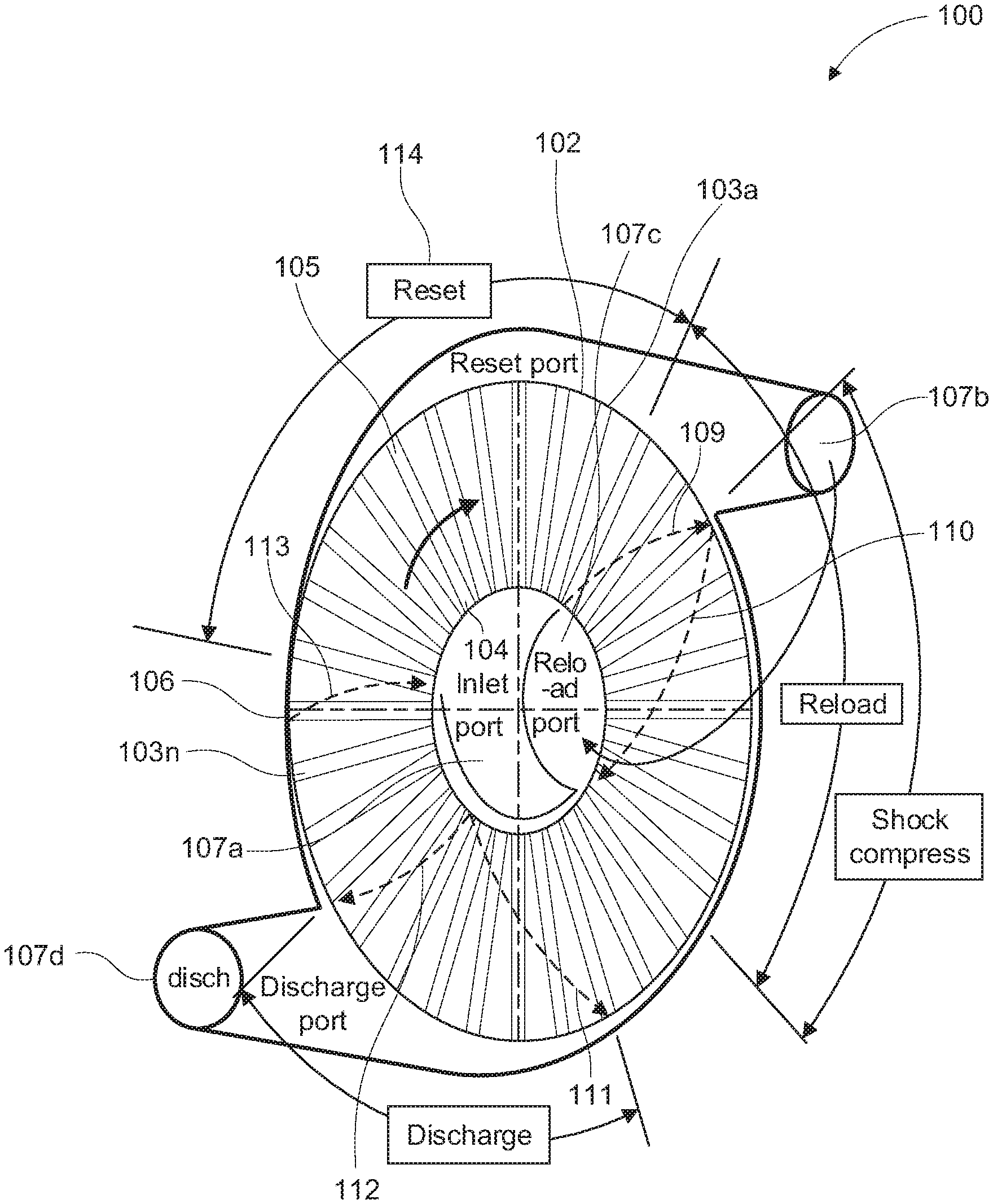
[0023] FIG. 1 illustrates an example gas compressor.
[0024] FIG. 2A illustrates an example gas compressor.
[0025] FIG. 2B illustrates and describes example flow states across moving waves of a channel of an example gas compressor.
[0026] FIG. 3 illustrates an example gas compressor an example of gas compressor timing and sequences.
[0027] FIG. 4 is an example operating cycle diagram of an example gas compressor.
[0028] FIG. 5 is an example turndown and control cycle diagram of an example gas compressor.
[0029] FIG. 6 illustrates an example gas compressor in a complete system.
[0030] FIG. 7 illustrates an example radial inlet, radial outlet impeller section view of an example gas compressor.
[0031] FIG. 8 illustrates an example axial inlet, axial outlet impeller of an example gas compressor.
[0032] FIG. 9 illustrates an example axial inlet, radial outlet impeller section view of an example gas compressor.
[0033] FIG. 10 illustrates an example axial inlet, radial outlet impeller and stator section view with two compression stages on a single impeller of an example gas compressor.
[0034] FIGS. 11A and 11B illustrate example operating cycles discharge flow data of example gas compressors.
[0035] FIG. 12 illustrates example pressure ratio for wave processes compared to isentropic flow process.
[0036] FIG. 13 is a block diagram illustrating an example method of operation of an gas compressor.
[0037] Corresponding reference characters indicate corresponding parts throughout the drawings.
DETAILED DESCRIPTION
[0038] Aspects of this disclosure utilize centrifugal work to drive an air flow, and controls shockwave strength to in a way that increases the air pressure of the air flow. The embodiments and examples described herein provide a centrifugal impeller including sequential shrouded channels, having an open entry portion (e.g., at a small diameter) and an open exit portion (e.g., at a comparatively larger diameter). The entry end of a channel and the exit end of the channel become intermittently blocked by one or more barriers as the centrifugal impeller rotates. The one or more barriers may define one or more a stator inlet ports or exit ports, which allows gas to enter or exit a sequential channels of the impeller as the shrouded channel passes a port and allows gas to be contained within a channel of the impeller as the shrouded channel passes a barrier (e.g., barrier wall). In examples, the rotor may rotate at a fixed speed, which may maintain the integrity of the wave field and port flows.
[0039] While the impeller rotates, centrifugal force increases the velocity of the gas flow within the sequential channels. In examples, the air flow may be captured and reloaded into other sequential channels of the same impeller. For example, as other sequential channels of the same impeller pass a reload port, which allows the captured air flow to reload into the passing sequential channels. As the sequential channels pass by a barrier, the velocity of the air flow causes the air flow to collide against the barrier causing the air flow velocity to dramatically drop and inducing a shockwave energized in the opposing direction of the centrifugal force. Strategic radial and/or angular placement of the barrier and/or the channels' shape and/or area provide a way to contain the results of the waves in increased or decreased pressure. As the impeller continues to rotate, the moving shockwave energy increases the pressure of the air flow located within the sequential channels. As the impeller continues to rotate, a shockwave moving in the opposite direction increases the pressure of the air flow located within the sequential channels. Further, if desired, as the impeller continues to rotate, a shockwave moving in the opposite direction increases the pressure of the air flow located within the sequential channels. After the desired number of shockwaves have occurred, as the impeller continues to rotate, the sequential channels to pass by a port causing an opening of an exit portion of the sequential channels. While the channel opens, the pressurized gas flows out of the sequential channels.
[0040] While the impeller rotates, centrifugal force increases the velocity of the gas flow during a reset phase, and shockwave energy (and in examples, centrifugal force) increases the pressure of the air flow curing a reload phase. Further rotation of the impeller causes the sequential channels to pass by a port causing an opening of an exit portion of the sequential channels during a discharge phase. While the channel opens, the pressurized gas flows out of the sequential channels. In examples, the discharge port is delimited by an inward running expansion wave and by the arrival of a reflected expansion wave.
[0041] Similar to typical centrifugal compressors, the gas enters the channel at low velocity and low pressure. Rotation of the impeller causes the individual shrouded channels to sequentially pass by a gas inlet port. As such, the individual shrouded channels are serially exposed to the gas inlet port causing the gas to sequential enter the shrouded channels at low velocity and low pressure. Also, similar to conventional centrifugal compressors, rotation of the impeller creates centrifugal force that drives the gas flow outward from the inside diameter (ID) of the stator toward the outside diameter (OD) of the stator. The velocity of the flow through a given channel begins at low velocity and increases as the channel rotates through the arc defined by the inlet port [reset process.
[0042] Conventional centrifugal compressors stop applying flow work once the gas flow reaches the stator OD, and the pressurized gas flow exits the stator through a volute moving to gas away from the impeller and stator and downstream to next stage of the overall system or to the user. As such, pressurized air provided by conventional centrifugal compressors are limited based at least on size and rotational speeds.
[0043] Systems and methods herein solve the above problems of conventional centrifugal compressors by provide a way to contain moving wave compression (e.g., shock waves) to create more parameters that can be used to increase the gas flow's pressure, while at the same time relying on centrifugal force to energy the gas flow's velocity, which minimizes the complexity and component part of the systems and methods. Traditionally, conventional centrifugal compressors viewed shock waves, which typically occur at the rotor blade tips, as a problem that rendered conventional centrifugal compressors unstable. As such, the industry has expended copious amounts of time, energy, and technology to minimize, eliminate, or otherwise accomodate shock waves occurring in conventional centrifugal compressors. As opposed to fighting shock waves, systems and methods herein seek to harness moving shock waves within the rotor channels in a manner that increases a gas flow's pressure. By harnessing and using shock waves (which achieve higher pressure ratios than isentropic flow process, which allows more mass in the channels, which permits the rotor to do more work), the same or more pressure is realized in the gas flow. By compressing air according to systems and methods described herein the same or more gas pressure may be generated with smaller rotors, operating at slower revolutions per minute. The benefits also include mechanical simplicity, high delivered pressure (for a given gas, diameter and speed) at relatively low gas flow, with a higher turn down capability (e.g., from 100% to 0% gas flow) at the design pressure ratio.
[0044] Nonetheless, examples herein are fundamentally distinct from conventional wave engines, which include a compression process, which compress gas using wave processes but depend on a thermal process, such as heat transfer or combustion, which creates an increased volume of hot gas to create compression energy. Conventional wave engines rely on thermal energy to drive and increase the pressure of a gas flow. In contrast, examples described herein rely on centrifugal force to drive and increase the velocity of a gas flow. Relying on thermal energy (e.g., combustible engines) to drive an air flow is less energy efficient, less environmentally sound, and significantly more mechanically complex as compared to relying on centrifugal force to drive and increase the velocity of a gas flow. Thus, examples described herein provide substantial benefits over traditional wave engines.
[0045] In examples, the channels are shrouded, with a constant area, and the stator ID and OD housing closely follows the curve of the impeller, and the sequential and rapid changes in the velocity and pressure of the gas flow generate sequential moving (e.g., inward and outward running) shock waves and expansion waves as the shrouded channels pass stator ports and walls.
[0046] The added centrifugal processes and moving wave processes improves the steady gas flow discharge, as explained above. Further, the centrifugal processes are initiated in sequence, within a single rotation of a centrifugal impeller providing improved control. Moreover, the close running ID and OD stator walls reduce leakage from high pressure regions to low pressure regions. The combination and sequence of centrifugal processes and moving wave processes create a higher stage pressure ratio, at lower gas flow, with high gas flow turndown as compared to a conventional centrifugal compressor with similar dimensions and operating speed. Energy is imparted to the gas flow by centrifugal work, with multiple stages of work, and compression/shockwave recovery of pressure on the impeller allow for the higher stage pressure ratio. Since the processes are initiated in sectors of the impeller rotation, less gas flow is processed than in a comparable centrifugal compressor. The impeller has constant area shrouded channels, radially oriented, with radial or axial inlets and with radial or axial channel outlets. Further still, there are two exit port gas flows per stage, each providing an opportunity to remove heat from the gas flow, which further increases the compressor's capacity.
[0047] In examples, changes of the angular location and of one or more stator inlet ports shape may change the air flow presentation to the rotor, which may be leveraged to increase optimization. In examples, changes of the angular location and shape of one or more stator exit ports change the acceptance of air flow, which may be leveraged to minimize flow loss. In examples, changing the angular location includes moving the leading edge and/or trailing edge of the port. In examples, changes of shapes and positions of exit diffusers may change the recovery of velocity head, which may be leveraged to increase recover of velocity head.
[0048] In examples, systems and methods may vary the rotational speed up or down slightly to mismatch the waves and resultant flows in the ports (e.g., to permit reduced flows or recirculated flows). Systems and methods may throttle the flow at the inlet port and/or throttle the reload flow. Systems and methods may "pinch throat" the discharge port.
[0049] The embodiments and examples described herein improve traditional centrifugal compressors by reusing the pressurized gas flow by injecting the pressurized gas flow back into the ID of the impeller via a second inlet port, which adds additional centrifugal energy to the gas flow before allowing the pressurized gas flow to be delivered to a downstream system or otherwise exit the compressor. For example, an exit port at the stator OD leads to a second inlet port adjacent the inner diameter of the impeller. Thus, the pressurized gas flow exiting the first exit port connects back toward the stator ID reenters the impeller via a second gas inlet port allowing the gas flow to enter a sequentially rotating channel.
[0050] FIG. 1 is an exemplary block diagram illustrating an example cross sectional view of a gas compressor 100. Gas compressor 100 includes an impeller 102 with radial channels 103a-103n having a substantially constant area. The channels 103a-103n are enclosed except at an opening 104 at an inner diameter (ID) and at an opening 105 at an outer diameter (OD). Channel ID openings may be radially or axially disposed. Channel OD openings may be radially or axially disposed.
[0051] Impeller 102 is coupled to a shaft (not shown) supported by bearings (not shown). The shaft is driven by a motor (not shown). Gas compressor 100 includes a stator 106 with ports 107a-107d that are adjacent and in close proximity to the impeller channel openings 104 and 105. The ports 107a-107d may be disposed at defined angular sectors of rotation, with defined relationships between some of the port edges. Two ports conduct gas flow to the impeller inlets. Two ports conduct gas flow away from the impeller outlets. The stator 106 contains the various pressures created within gas compressor 100, conducts gas flow, and converts pressure to velocity at the inlet ports 107a-107b, which function as nozzles and converts velocity to pressure at the exit ports 107c-107d, which function as diffusers. The stator 106 supports the bearings (not shown) and the coupling to the drive motor (not shown). Stator walls run close to impeller channel openings and prevent leakage of gas from high pressure regions to low pressure regions.
[0052] In examples, shaft bearings (not shown) may be included that support the rotor. Further the shaft bearings may permit rotation, locate rotor radially for close running of seals, locate rotor axially for close running of seals, inhibit vibration, resist unbalanced pressure forces--axial and radial.
[0053] Rotation of the impeller 106 exposes the impeller channel openings sequentially to the stator ports and the leading edges and trailing edges of the ports, initiating a sequence of gas flow processes. In examples, Port 107a is the first inlet port, which is adjacent to the impeller channel ID and admits low pressure gas onto the impeller 102. Port 107c is the reset port, which is adjacent to the impeller channel (OD) and conducts gas flow away from the impeller 102 for reduction of velocity and recovery of pressure after an initial stage of centrifugal compression. First inlet port 107a and reload port 107c together enable gas flow on the impeller 102 to reset from an initial state in the impeller channels of substantially zero velocity and low pressure to a state of relatively high velocity, at low pressure and at a centrifugal pressure distribution dictated by the impeller dimensions and rotational speed.
[0054] Port 107b is the reset port, which is adjacent to the impeller channel ID, immediately after the inlet port 107a in the sequence of rotation and in fluid connection with reload port 107c. Reload port 107c admits the gas flow from OD reset port 107b back onto the impeller 102 (e.g., reentrant gas flow) driving the impeller gas flow to an even higher velocity and pressure caused by an outward running moving shockwave 109. Ports 107a, 107b, and 107c together create a high velocity gas flow through the impeller 102 at a first intermediate level of pressure.
[0055] The trailing edge of reload port 107c closes off the impeller OD channel exit, bringing the gas flow to zero velocity on the impeller 102 and initiating an inward running moving shockwave 110 that raises the pressure. When the inward running shockwave 110 reaches the ID of the impeller channel openings the trailing edge of reset port 107b closes the opening and traps high pressure gas on the impeller 102 causing the highest pressure within the compressor cycle, and highest temperature. The gas flow has substantially zero velocity relative to the impeller 102 and has a centrifugal pressure distribution from ID to OD dictated by the impeller dimensions and rotational speed.
[0056] Continued rotation of the impeller 102 exposes the channel OD to the discharge port 107d, wherein gas flow is conducted away from the impeller 102, for reduction of velocity and recovery of pressure in a diffuser and then for delivery to a user or to a subsequent compression stage (not shown). The static pressure in discharge port 107d is lower than the peak pressure achieved on the impeller 102. Opening of the impeller channel at the leading edge of discharge port 107d initiates an inward running moving expansion wave 111 that signals expansion of the gas flow into the discharge port 107d. The expansion wave 111 reflects from the inner stator wall adjacent to the impeller ID as an outward running moving expansion wave 112, which brings gas flow on the impeller 102 to substantially zero velocity relative to the impeller 102, at low pressure relative to the impeller 102, with a pressure distribution dictated by the impeller dimensions and rotational speed. When the outward running expansion wave 112 reaches the impeller OD, the trailing edge of discharge port 107d closes of the channel, causing completion of the sequence, which may be repeated substantially continuously. Further, when the outward running expansion wave 112 reaches the impeller OD, wave 113, which may be of relatively of small strength and may be either an inward running expansion wave or a shock wave, signals the opening of inlet port 107a and reload port 107c to begin the reset process 114.
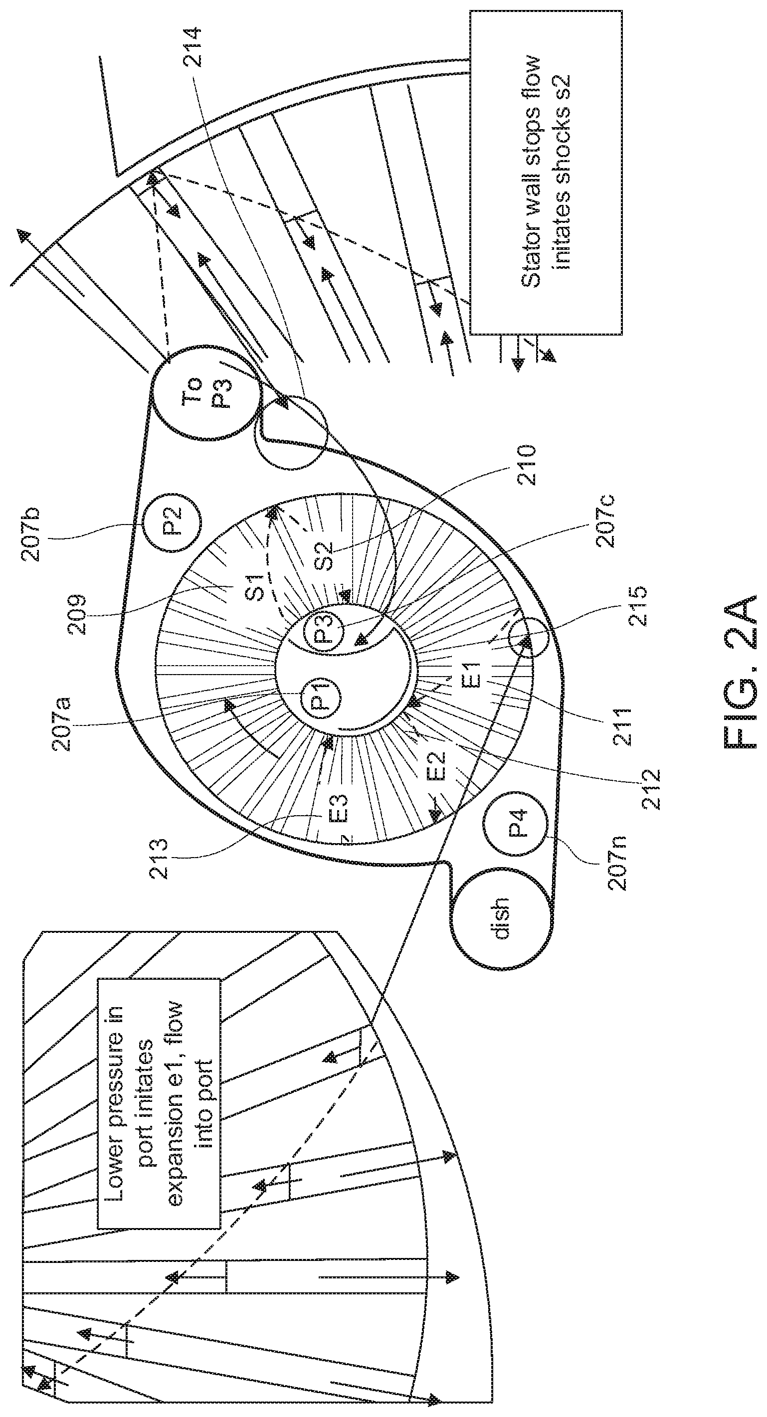
[0057] FIG. 2A illustrates an example gas compressor 200. In example gas compressor 200 moving waves are initiated in four ways, each following a threshold mismatch (e.g., near-instantaneous mismatch) of pressure and/or velocity. Shockwave 209 is initiated by the mismatch of total pressure and velocity as the impeller ID channel opening is exposed to the reload port 207c. Shockwave 209 drives the flow on the impeller at the trailing edge of the inlet port 107a to a higher velocity and pressure (e.g., highest velocity of this partial rotation of the cycle). Shockwave 210 is initiated by stoppage of the high velocity and intermediate pressure flow at the trailing edge of the reset port 207b, positioned at location 214. Location 214 is enlarged on the right side of FIG. 2. Shockwave 210 results in gas flow with zero velocity relative to the impeller, at the highest pressure.
[0058] Expansion wave 211 is initiated by exposure of the impeller OD opening to the discharge port 207n, at a static pressure less than the pressure on the impeller, which occurs at location 215. Location 215 is enlarged on the left side of FIG. 2. The expansion wave 211 signals the flow to move, off of the impeller, into the discharge port 207n. Expansion wave 212 is formed as expansion wave 211 reflects from the ID stator wall causing a mismatch of the velocity defined by expansion wave 211 and the boundary condition of the stator wall which is zero velocity.
[0059] Since channel openings are not instantaneous, a wave formation event occurs, wherein shock waves are formed initially, that steepens to a shock or a pressure decrease that diffuses as a spread-out expansion wave. This creates wave timing differences from exact waves, potential losses and carry-over flows that can be determined and accounted for. Expansion waves propagate into a flow region with acoustic velocity. Shocks propagate into a flow region with a velocity that exceeds the speed of sound for the region. The equations for moving waves 220 and 230 are shown in FIG. 2B. Constant area channels with a consistent shape improve propagation of moving waves as compared to inconsistent area channels and/or inconsistently shaped channels.
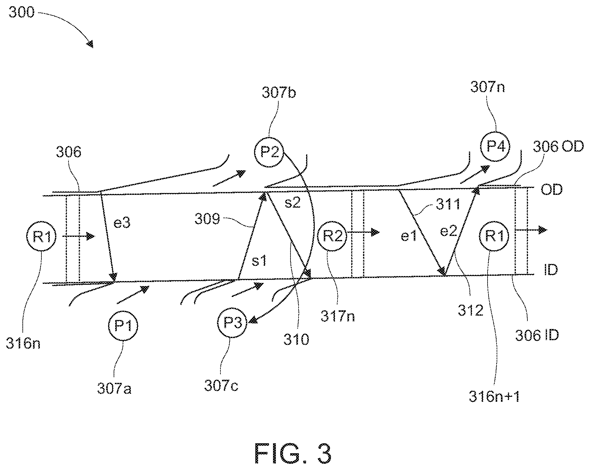
[0060] FIG. 3 illustrates an example of gas compressor timing and sequences 300. Impeller state 316n is the low pressure, zero velocity condition, after expansion and before the reset group of processes is initiated. Impeller state 317n is the high pressure, zero velocity condition. Stator 306 includes inlet port 307a, reset port 307b, reload port 307c, and discharge port 307n. Reset port 307b is fluidly coupled to reload port 307c direct the collected reset flow back on to the impeller at the reload port 307c. The positions of edges of one or more of the ports 307a-307n may be based on the flow or wave processes. In examples, the leading edges for inlet port 307a and reset port 307b are at the same rotation angle. The angular length of the inlet port 307a is sufficient to achieve the desired mass flow in the port and flow Mach number at the trailing edge of the inlet port 307a. The desired mass flow and flow Mach number may be determined, calculated, adjustable, and selectable.
[0061] The trailing edge of reset port 307b is a one wave transit time after the trailing edge of inlet port 307a to allow for the passage of shockwave 309. The trailing edge of reload port 307c is located by the transit time of inward running shockwave 310 and its arrival at the rotor ID. The length of discharge port 307n may be based on the transit time of expansion waves 311 and 312. Because expansion waves are diffusive (e.g. the wave spreads out as it travels), the location of the trailing edge of discharge port 307n is positioned is at the point where the static pressure on the rotor moves below (e.g., drops) the static pressure in the discharge port 307n. In examples, the angle devoted to the highest pressure portion of the cycle may be minimized to further reduce leakage loss. In some examples, the cycle angle duration may not match angle available, and extra rotation angle may be left after the discharge port 307n, before the leading edges of the inlet port 307a and reset port 307b.
[0062] In examples, the stator wall's outside diameter 3060D and inside diameter 3061D may be located close to the impeller ID and OD channel openings (whether axial or radial), which improves containment of the various levels of pressure and to prevent leakage from high pressure regions to low pressure regions that would adversely affect the processes. Further, port leading and trailing edges may also be located close to the impeller ID and OD channel openings (whether axial or radial), which further improves pressure containment and leakage prevention. In some examples, the shock waves may have a small deviation from ideal (typically less than 1.5% loss of total pressure ratio across the shock).
[0063] Diffusion of flow to reduce velocity and recover pressure occurs in stator OD ports (reset port 307b and discharge 307n). An exemplary static pressure for discharge 307n may be the square root of the pressure ratio achieved at State D (shown in FIG. 4), which is the maximum max pressure on the impeller relative to the inlet total pressure. Positioning the ports such that static pressure for discharge 307n is at State D optimizes compression by making use of two expansion waves of equal pressure ratio (e.g., expansion waves 311 and 312).
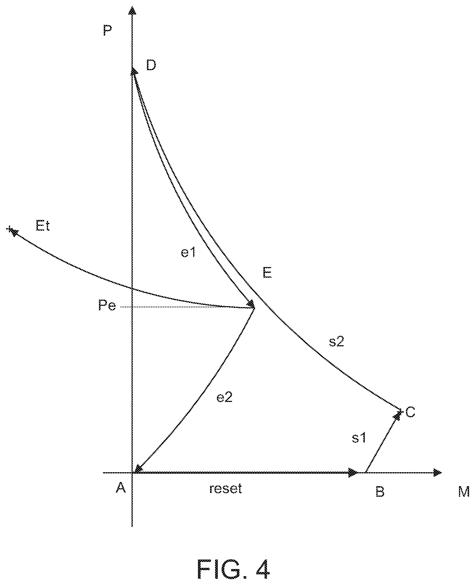
[0064] FIG. 4 is an example operating cycle diagram of an example gas compressor. Diagram 400 maps an sequential processes of an example centrifugal wave compressor operating cycle in a graph of Pressure vs. Mach number for the flow states at the rotor outside diameter. (Mach number=(gas flow velocity/speed of sound)).
[0065] Beginning at point A, is a very low flow velocity through the impeller, at low pressure. This is the impeller condition at the opening of the inlet and reset ports. From point A, the flow resets to velocity and pressure point B into the reset port. The reset port flow, having an elevated total pressure, may be loaded back onto the impeller ID at the reload port, initiating an outward running shockwave s1 and returning the flow on the impeller at intermediate pressure with highest velocity state point C.
[0066] The flow is stopped on the impeller at the trailing edge of the reset port, which initiates an inward running shockwave s2, converting the velocity to high pressure with zero velocity in the rotor channel at point D. The flow is then expanded to an intermediate static pressure E into the discharge port. The expansion is defined by expansion wave e1 and reflected expansion wave e2. After e2, the flow on the impeller is at low pressure and zero velocity returning to point A. In examples, the steady flow into the discharge port (stator) is diffused to low velocity and total pressure Et. An optimal design may position the discharge port static pressure Pe to be the square root of the pressure ratio of Pd/Pa, which delivers an optimal combination of flow and pressure to the discharge port by two balanced expansion waves e1 and e2.
[0067] FIG. 5 is an example turndown and control cycle diagram of an example gas compressor. In examples, one or more of wave compressors described herein may turn down flow from 100% to 0% at a target delivered pressure. Reduction of Point B in M to B' results in a reduction of mass on the impeller (B'), which reduces the mass flow delivered at C' or Ct'. Centrifugal work is done in discrete sectors of rotation, and is positively accelerates making surge or stall events unlikely. The recovery of velocity to pressure on the impeller (S2) is driven by a strong moving wave. Waves S1, E1 and E3 (D1' to D2') are accelerative.
[0068] Control (e.g., reduction of mass flow) may be implemented effected by a valve in the inlet port and nozzle that adjusts inlet port total pressure. Additionally or alternatively, the inlet port may include a variable leading edge that is dynamically adjustable to change the rotational sector available for reset (e.g., reducing the Mach number at E to E' and resulting Pa and Ma). Additionally or alternatively, the impeller speed maybe dynamically adjustable to implement control by creating a mismatch between the wave field and the port edges, which causes a limitation or recirculation of flow. Control may be initiate and or terminated manually and/or automatically based on a target pressure or a reduce pressure at a target flow. In examples, a target pressure or a reduce pressure at a target flow may be dependent one or more characteristic of the downstream system. Further, flow energy remaining on the rotor at reduced flow (D1') may be recovered by an extra expansion wave A1' to a2', and the recovered total pressure is available in the reset port, minus diffusion loss.
[0069] FIG. 6 illustrates an example gas compressor of an example system 600. In examples, a flow enters through a filter 601, which removes particulates. Then, flow enters the impeller through the inlet port 602. Flow exits the impeller, at an elevated pressure and temperature, after a single stage of centrifugal compression, at the reset port 603. Following diffusion in the stator, to recover velocity as pressure, flow exits the unit. Flow goes through a first cooler 604, wherein heat is transferred to cooling media and liquid water condensed from the gas is drained from the cooler by a drain.
[0070] Flow is reintroduced to the impeller at the reload port 605, wherein the flow is further compressed on the impeller and exposed to the discharge port 606 at elevated pressure and temperature. Following diffusion in the stator, to recover velocity as pressure, the flow exits the unit and goes to a second cooler 607, wherein heat is transferred to cooling media, and liquid water condensed from the gas is drained from the cooler 607 by a drain. Thereafter, the flow, flows out at 608 and is delivered to a user or to a subsequent compression stage.
[0071] FIG. 7 illustrates an example radial inlet, radial outlet impeller 700 section view of an example gas compressor. Inlet port 707a or reset port 707b and discharge port 707n are shown in a radial inlet and outlet configuration.
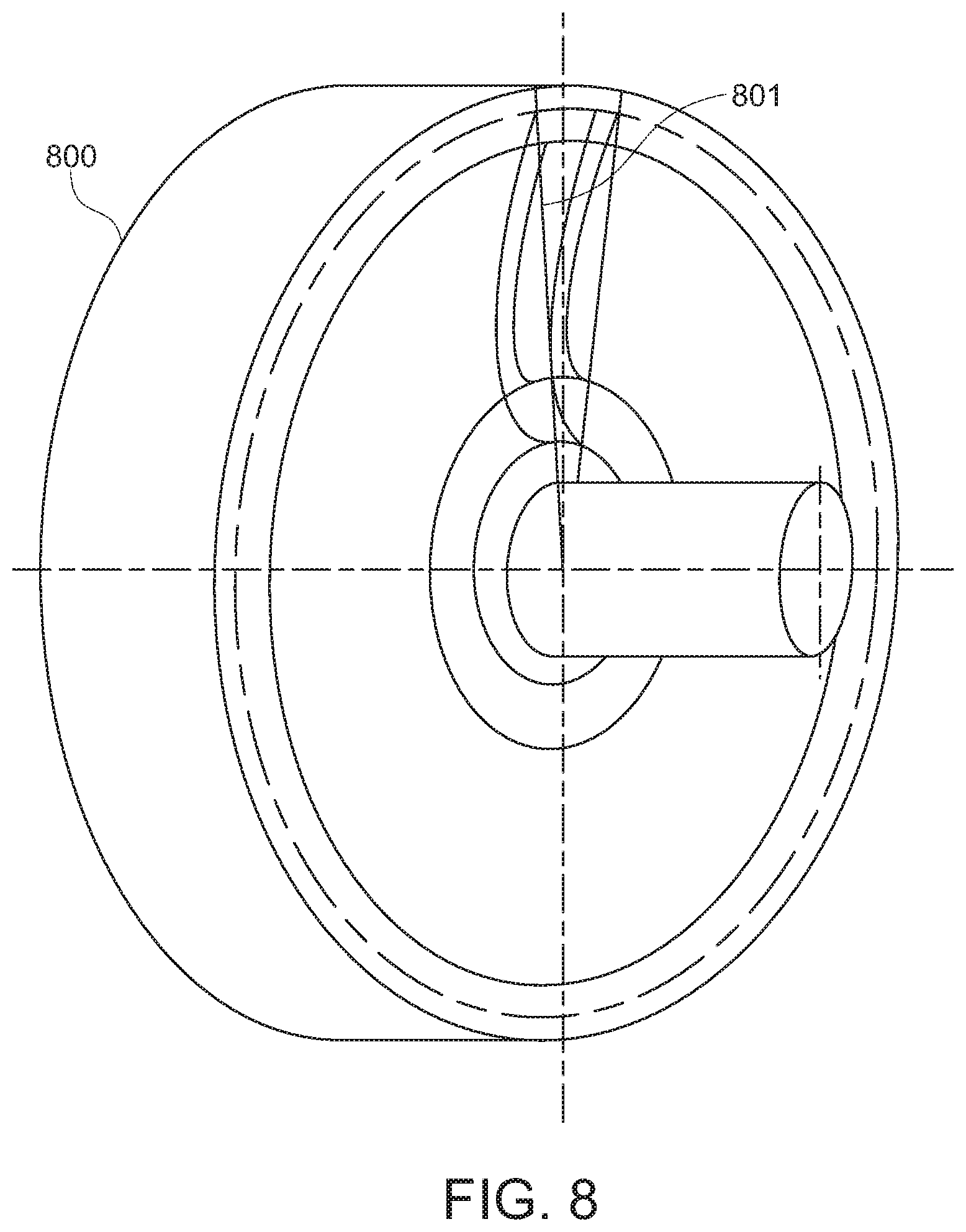
[0072] FIG. 8 illustrates an example axial inlet, axial outlet impeller 800 of an example gas compressor. An axial face radial channel 801 is shown in an axial inlet and axial outlet configuration.
[0073] FIG. 9 illustrates an example axial inlet, radial outlet impeller 900 section view of an example gas compressor. Channel 901 is shown in an axial inlet radial outlet configuration.
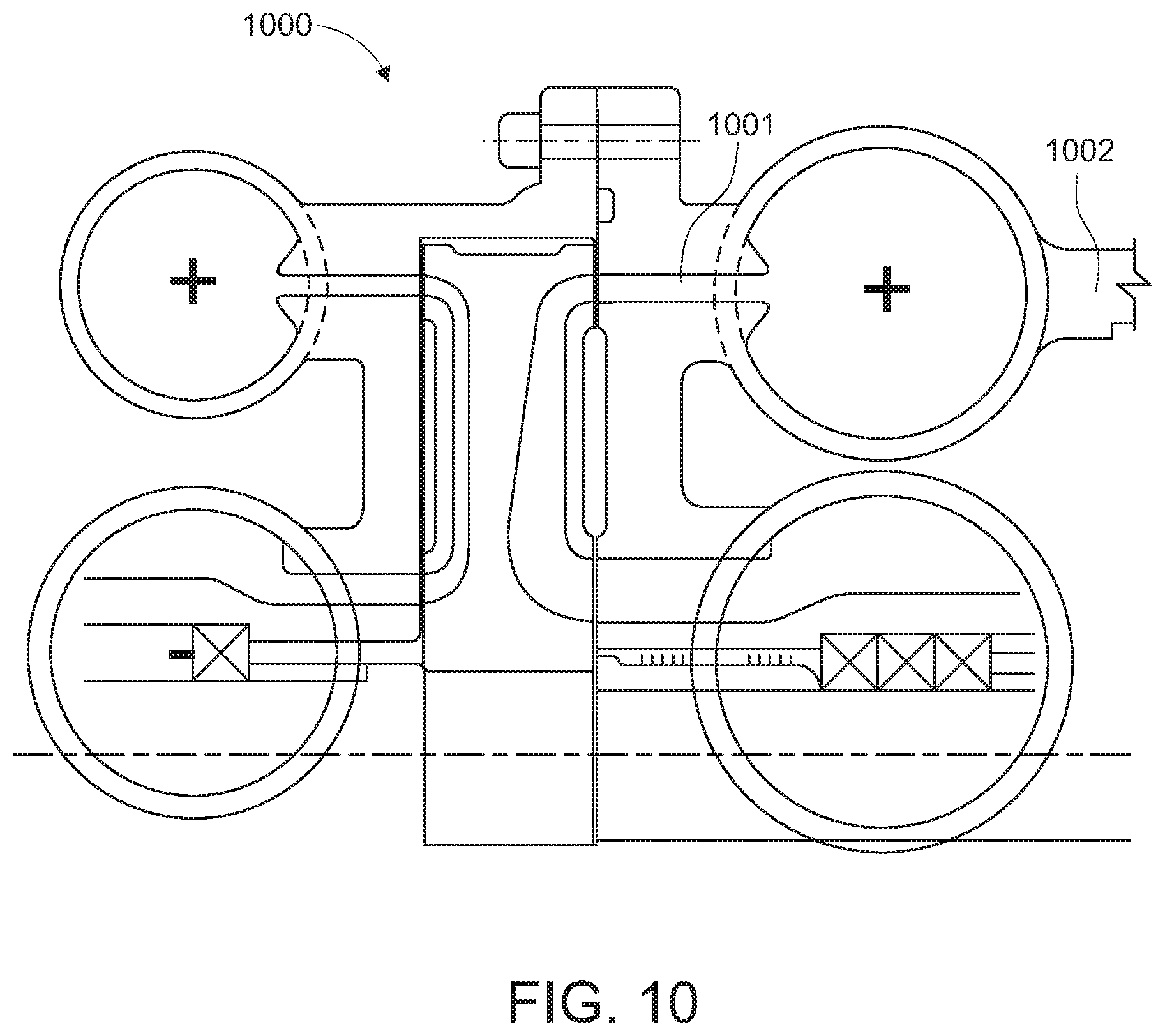
[0074] FIG. 10 illustrates an example axial inlet, radial outlet impeller and stator section view with two compression stages on a single impeller of an example gas compressor 1000. Example inlet 1001 and example outlet 1002 is shown in an axial inlet and radial outlet configuration.
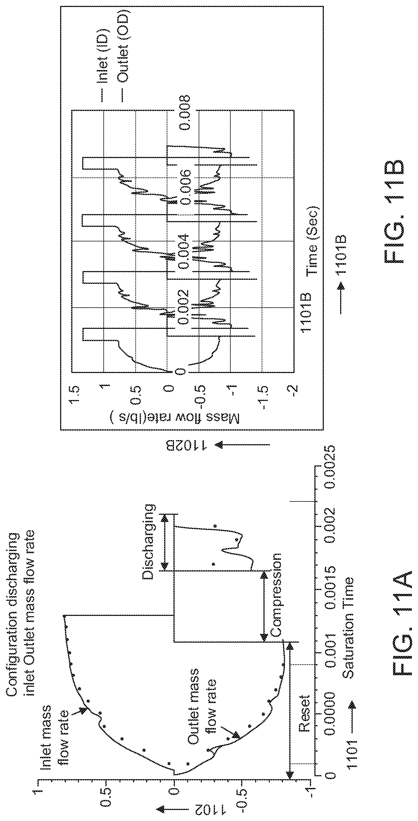
[0075] FIG. 11A illustrates an example operating cycle discharge flow data of an example three port gas compressor. X axis 1101 represents time, and Y axis 1102 represents the flow. FIG. 11B illustrates an example operating cycle discharge flow data of an example four port gas compressor (e.g., as shown in FIG. 1). X axis 1101B represents time, and Y axis 1102B represents the flow. FIG. 12 shows example pressure ratio for wave processes compared to isentropic flow process. X axis 1203 represents the flow Mach number, and the Y axis 1204 represents pressure ratio.
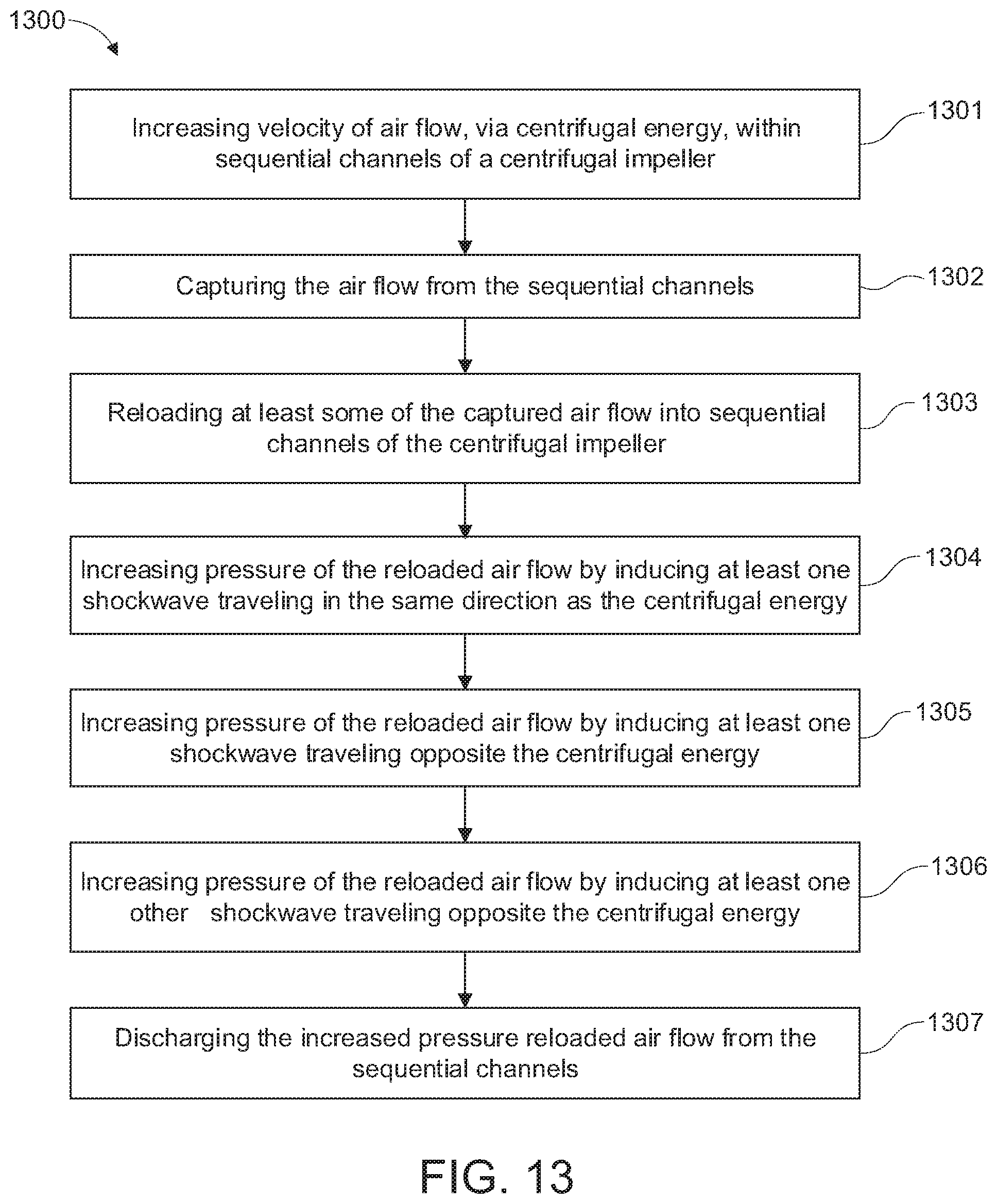
[0076] FIG. 13 is an example block diagram illustrating an example method 1300 of compressing gas. In this example method, the reset phase, reload phase, and discharge phase illustrated in FIG. 1 is shown by way of example. FIG. 13 is an example block diagram illustrating an example method 1300 of compressing gas. In this example method, the reset phase, reload phase, and discharge phase illustrated in FIG. 1 is shown by way of example. At operation 1301, example method 1300 increases velocity of air flow, via centrifugal energy, within sequential channels of a centrifugal impeller. At operation 1302, example method 1300 captures the air flow from the sequential channels. At operation 1303, example method 1300 reloads at least some of the captured air flow into sequential channels of the centrifugal impeller. At operation 1304, example method 1300 increases pressure of the reloaded air flow by inducing at least one shockwave traveling in the same direction as the centrifugal energy. At operation 1305, example method 1300 increases pressure of the reloaded air flow by inducing at least one shockwave traveling opposite the centrifugal energy. At operation 1306, example method 1300 increases pressure of the reloaded air flow by inducing at least one other shockwave traveling opposite the centrifugal energy. At operation 1307, example method 1300 discharges the increased pressure reloaded air flow from the sequential channels. Some steps of example method 1300 may be skipped if desired and additional step may be added if desired.
[0077] Example 1300 may be used according to any and/or any combination of the example impellers, example gas compressors and/or systems described and/or illustrated herein (e.g., FIGS. 1-12). Further, example method 1300 may include additional aspects for example, a temperature and pressure of the gas flow when exiting the first exit port is elevated compared to the temperature and pressure of the gas flow prior to entering the first inlet port. In another aspect, a temperature and pressure of the gas flow when exiting the discharge port is elevated compared to the temperature and pressure of the gas flow when exiting the first exit port. Another aspect also includes: after the releasing the gas flow via the first exit port, intercooling the gas flow before the reintroducing the gas flow via a second inlet port. Another aspect also includes, after the discharging the gas flow via the discharge port, delivering the gas flow to a subsequent compression stage. Another aspect also includes, detecting a characteristic of a downstream operation; and adjusting a target pressure or a target gas flow of the centrifugal impeller. Another aspect also includes: detecting a target pressure or a target gas flow of the centrifugal impeller; and adjusting a mass gas flow at the first inlet port by at least one of: adjusting a valve at the first inlet port, adjusting a nozzle at the first inlet port, adjusting a position of an adjustable leading edge of the first inlet port, and adjusting a rotation speed of the centrifugal impeller.
Additional Examples
[0078] A first aspect is directed to a gas compressor. Specifically, the gas compressor involves: a centrifugal impeller comprising constant area shrouded channels and a stator. The stator includes: an inside diameter adjacent at least two inside diameter gas ports including a first inlet port having a leading edge and a trailing edge; a second inlet port having a leading edge and a trailing edge; and an outside diameter adjacent at least two outside diameter gas ports. The outside gas ports include: a first exit port having a leading edge and a trailing edge, and a second exit port having a leading edge and a trailing edge. A channel of the centrifugal impeller passes the two inside diameter gas ports and the two outside diameter gas ports during a single revolution of the centrifugal impeller.
[0079] In another aspect, the first exit port fluidly couples to the second inlet port.
[0080] In another aspect, the leading edges and the trailing edges of the two inside diameter gas ports and two outside diameter gas ports are positioned based at least on a selected mass gas flow, a selected gas flow Mach number, and wave trajectory.
[0081] In another aspect, the leading edge of the first inlet port and the leading edge of the first exit port are positioned at a same rotation angle.
[0082] In another aspect, an angular length of the first inlet port is based at least on: a selected mass gas flow of the first inlet port, and a selected gas flow Mach number at the trailing edge of the first inlet port.
[0083] In another aspect, an angular length of the first inlet port is adjustable via adjustable positions of the leading edge of the first inlet port.
[0084] In another aspect, an angular distance between the trailing edge of the first inlet port and the trailing edge of the first exit port provides at least one moving shockwave that travels from the inside diameter of the stator to the outside diameter of the stator.
[0085] In another aspect, an angular distance between the trailing edge of the first exit port and the trailing edge of the second inlet port provides at least one moving shockwave that travels from the outside diameter of the stator to the inside diameter of the stator.
[0086] In another aspect, an angular length of the second exit port is based at least on a selected travel time of an moving expansion wave that travels from the outside diameter of the stator to the inside diameter of the stator and a reflective expansion wave that travels from the inside diameter of the stator to the outside diameter of the stator.
[0087] In another aspect, the trailing edge of the second exit port is positioned at a location that static pressure on the impeller reduces below static pressure in the second exit port.
[0088] In another aspect, an angular distance between the trailing edge of the second inlet port and the leading edge of the second exit port is a shorter than any other angular distance between any other trailing edge of the stator and any other leading edge of the stator.
[0089] Another aspect is directed to a gas compression method. Specifically, the gas compression method includes: receiving a gas flow into one or more shrouded channels of a centrifugal impeller via a first inlet port adjacent an inside diameter of a stator during a partial revolution of the centrifugal impeller; releasing the gas flow from the one or more channels of the centrifugal impeller via a first exit port adjacent an outside diameter of the stator during a subsequent partial revolution of the centrifugal impeller; reintroducing the gas flow into the one or more channels of the centrifugal impeller via another inlet port adjacent the inside diameter of the stator during another subsequent partial revolution of the centrifugal impeller; and discharging the gas flow from the one or more channels of the centrifugal impeller via a discharge port adjacent the outside diameter of the stator during an additionally subsequent partial revolution of the centrifugal impeller, wherein a sum of the partial revolution, the subsequent partial revolution, the another subsequent partial revolution, and the additionally subsequent partial revolution is less than a single revolution of the centrifugal impeller.
[0090] In another aspect, a temperature and pressure of the gas flow when exiting the first exit port is elevated compared to the temperature and pressure of the gas flow prior to entering the first inlet port.
[0091] In another aspect, a temperature and pressure of the gas flow when exiting the discharge port is elevated compared to the temperature and pressure of the gas flow when exiting the first exit port.
[0092] Another aspect also includes: after the releasing the gas flow via the first exit port, intercooling the gas flow before the reintroducing the gas flow via a second inlet port.
[0093] Another aspect also includes: after the discharging the gas flow via the discharge port, delivering the gas flow to a subsequent compression stage.
[0094] Another aspect also includes: detecting a characteristic of a downstream operation; and adjusting a target pressure or a target gas flow of the centrifugal impeller.
[0095] Another aspect also includes: detecting a target pressure or a target gas flow of the centrifugal impeller; and adjusting a mass gas flow at the first inlet port by at least one of: adjusting a valve at the first inlet port, adjusting a nozzle at the first inlet port, adjusting a position of an adjustable leading edge of the first inlet port, and adjusting a rotation speed of the centrifugal impeller.
[0096] Another aspect is directed to a centrifugal moving wave gas compressor. Specifically, the centrifugal moving wave gas compressor involves: a centrifugal impeller comprising constant area shrouded channels and a stator. The stator includes: a first gas inlet port adjacent an inside diameter of the stator operable to receive a gas flow having an initial pressure into the impeller, a first gas exit port adjacent an outside diameter of the stator operable to release the gas flow from the impeller at a first elevated pressure after a partial revolution of the impeller, a reload gas port adjacent an inside diameter of the stator operable to reload the gas flow into the impeller, and a discharge gas port adjacent an outside diameter of the stator operable to rerelease the gas flow from the impeller at a second elevated pressure after a partial revolution of the impeller. The second elevated pressure is higher than the first elevated pressure, which is higher than the initial pressure, and wherein a channel of the centrifugal impeller passes the two inside diameter gas ports and the two outside diameter gas ports during a single revolution of the centrifugal impeller.
[0097] In another aspect, at least an outward moving first shockwave raises the initial pressure to the first elevated pressure, and wherein at least an inward moving second shock wave, an inward moving expansion wave, and an outward moving expansion wave raises the first elevated pressure to the second elevated pressure.
[0098] The examples and designs illustrated and described herein as well as examples and designs not specifically described herein (e.g., impellers, stators, and/or compressors not specifically illustrated in the figures) are within the scope of aspects of the disclosure. The order of execution or performance of the operations in examples of the disclosure illustrated and described herein is not essential, unless otherwise specified. That is, the operations may be performed in any order, unless otherwise specified, and examples of the disclosure may include additional or fewer operations than those disclosed herein. For example, it is contemplated that executing or performing a particular operation before, contemporaneously with, or after another operation is within the scope of aspects of the disclosure.
[0099] When introducing elements of aspects of the disclosure or the examples thereof, the articles "a," "an," "the," and "said" are intended to mean that there are one or more of the elements. The terms "comprising," "including," and "having" are intended to be inclusive and mean that there may be additional elements other than the listed elements. The term "exemplary" is intended to mean "an example of." The phrase "one or more of the following: A, B, and C" means "at least one of A and/or at least one of B and/or at least one of C."
[0100] Having described aspects of the disclosure in detail, it will be apparent that modifications and variations are possible without departing from the scope of aspects of the disclosure as defined in the appended claims. As various changes could be made in the above constructions, products, and methods without departing from the scope of aspects of the disclosure, it is intended that all matter contained in the above description and shown in the accompanying drawings shall be interpreted as illustrative and not in a limiting sense.
[0101] While the disclosure is susceptible to various modifications and alternative constructions, certain illustrated examples thereof are shown in the drawings and have been described above in detail. It should be understood, however, that there is no intention to limit the disclosure to the specific forms disclosed, but on the contrary, the intention is to cover all modifications, alternative constructions, and equivalents falling within the spirit and scope of the disclosure.
* * * * *
D00000
D00001
D00002
D00003
D00004
D00005
D00006
D00007
D00008
D00009
D00010
D00011
D00012
D00013

D00014
XML
uspto.report is an independent third-party trademark research tool that is not affiliated, endorsed, or sponsored by the United States Patent and Trademark Office (USPTO) or any other governmental organization. The information provided by uspto.report is based on publicly available data at the time of writing and is intended for informational purposes only.
While we strive to provide accurate and up-to-date information, we do not guarantee the accuracy, completeness, reliability, or suitability of the information displayed on this site. The use of this site is at your own risk. Any reliance you place on such information is therefore strictly at your own risk.
All official trademark data, including owner information, should be verified by visiting the official USPTO website at www.uspto.gov. This site is not intended to replace professional legal advice and should not be used as a substitute for consulting with a legal professional who is knowledgeable about trademark law.