Downhole Power Generation
Grueschow; Eric R. ; et al.
U.S. patent application number 17/013146 was filed with the patent office on 2021-04-01 for downhole power generation. The applicant listed for this patent is ExxonMobil Upstream Research Company. Invention is credited to Eric R. Grueschow, Michael C. Romer.
| Application Number | 20210095547 17/013146 |
| Document ID | / |
| Family ID | 1000005078007 |
| Filed Date | 2021-04-01 |


| United States Patent Application | 20210095547 |
| Kind Code | A1 |
| Grueschow; Eric R. ; et al. | April 1, 2021 |
Downhole Power Generation
Abstract
A gas lift valve (GLV) is described herein. The GLV includes a power generation device that uses a fluid flowing through the GLV to generate power.
| Inventors: | Grueschow; Eric R.; (Houston, TX) ; Romer; Michael C.; (The Woodlands, TX) | ||||||||||
| Applicant: |
|
||||||||||
|---|---|---|---|---|---|---|---|---|---|---|---|
| Family ID: | 1000005078007 | ||||||||||
| Appl. No.: | 17/013146 | ||||||||||
| Filed: | September 4, 2020 |
Related U.S. Patent Documents
| Application Number | Filing Date | Patent Number | ||
|---|---|---|---|---|
| 62907056 | Sep 27, 2019 | |||
| Current U.S. Class: | 1/1 |
| Current CPC Class: | E21B 43/123 20130101; E21B 41/0085 20130101 |
| International Class: | E21B 41/00 20060101 E21B041/00; E21B 43/12 20060101 E21B043/12 |
Claims
1. A method for generating power within a wellbore, the method comprising: passing an injection fluid into a wellbore in fluid communication with a subsurface formation; mixing the injection fluid with formation fluids to form a produced fluid; flowing the produced fluid through the wellbore to a wellhead; generating power by passing a power generation fluid through a gas lift valve (GLV); and wherein the power generation fluid is one of a portion of the injection fluid, a portion of the produced fluid or combination thereof.
2. The method of claim 1, wherein the injection fluid is a compressed gas and is passed into an annulus within the wellbore between a well casing and a production tubing.
3. The method of claim 1, comprising determining an amount of power to be generated by the GLV.
4. The method of claim 1, wherein the GLV is a valve configured to control flow of the injection fluid and is associated gas lift operations.
5. The method of claim 1, further comprising communicating from the GLV to a control unit at the surface of the wellbore.
6. The method of claim 1, wherein the generating power further comprising rotating a rotary assembly in the power generation device to generate current in an electrical generator.
7. The method of claim 1, comprising disconnecting a power storage device from the power generation device using a switch when power storage within the power storage device is maximized.
8. The method of claim 1, further comprising performing well optimization from the power generated by the GLV to power a device, wherein performing well optimization comprises: obtaining data from a sensor within the wellbore; storing the data from the sensor in a memory device; and transmitting the data from the senor to a data transmitter to a data receiver.
9. A hydrocarbon system comprising: a wellhead; a wellbore in fluid communication with the wellhead and a subsurface formation; well casing disposed within the wellbore, wherein the well casing provides one or more fluid flow paths from the subsurface formation to the wellhead; a production tubing disposed within the wellbore and in fluid communication with the wellbore; a gas lift valve (GLV) associated with the production tubing within the wellbore, wherein the GLV comprises a power generation device that uses a fluid flowing through the GLV to generate power.
10. The hydrocarbon system of claim 9 further comprising a coupling configured to inject a compressed gas into the wellbore, wherein the compressed gas is passed through the GLV to generate power.
11. The hydrocarbon system of claim 9, wherein the production tubing includes one or more mandrels and a production packer, wherein one of the one or more mandrels includes the GLV.
12. The hydrocarbon system of claim 9, wherein the GLV comprises: a power generation device configured to use the fluid flowing through the GLV to generate power; a power storage device configured to store the power generated by the power generation device; and a well optimization device configured to use the power stored within the power storage device, to collect data from one or more sensors associated with the wellbore operations, to store the data from the sensor, and transmit the data from the sensor.
13. The hydrocarbon system of claim 12, wherein the power generation device comprises a rotary assembly and an electrical generator.
14. The hydrocarbon system of claim 12, wherein the well optimization device comprises at least one of a sensor, a memory device, or a data transmitter.
15. A gas lift valve (GLV), comprising a power generation device that uses a fluid flowing through the GLV to generate power.
16. The GLV of claim 15, wherein the power generation device is located within an internal chamber of the GLV.
17. The GLV of claim 15, wherein the GLV is configured to open and to close at pressures in the tubing or annulus, depending on the specific application and wherein an open position of the GLV corresponds to a power generation mode of the GLV.
18. The GLV of claim 15, wherein the GLV comprises: a housing enclosing an internal chamber; an internal nozzle; a power generation device disposed in the internal chamber, wherein the power generation device is configured to convert energy from a compressed gas flowing through the GLV into electricity; and a power storage device configured to store the power generated by the power generation device; and a well optimization device configured to use the power stored within the power storage device, to collect data from one or more sensors associated with the wellbore operations, to store the data from the sensor, and to transmit the data from the sensor.
19. The GLV of claim 18, wherein the power generation device comprises a rotary assembly and an electrical generator.
20. The GLV of claim 19, wherein the rotary assembly comprises a paddlewheel or a turbine.
Description
CROSS-REFERENCE TO RELATED APPLICATION
[0001] This application claims the benefit of U.S. Provisional Application 62/907,056 filed Sep. 27, 2019 entitled DOWNHOLE POWER GENERATION, the entirety of which is incorporated by reference herein.
FIELD
[0002] The techniques described herein relate to downhole power generation. More particularly, the techniques described herein relate to power-generating gas lift valves (GLVs).
BACKGROUND
[0003] This section is intended to introduce various aspects of the art, which may be associated with embodiments of the present techniques. This discussion is believed to assist in providing a framework to facilitate a better understanding of particular aspects of the present techniques. Accordingly, it should be understood that this section should be read in this light, and not necessarily as admissions of prior art.
[0004] During the drilling of a well, large diameter wellbores are cased leading to narrow diameter wellbores which are also cased, finally leading to the production zones in the reservoir. As each section is cased, concrete is injected around the casing to hold it in place. The well is then completed by operations to begin the production of hydrocarbon fluids from the reservoir. The completions include the formation of perforations through the casing and concrete of the final section into the reservoir using a perforation gun. Production tubing is then inserted down the wellbore into the production zone. The production tubing may include equipment that enables the use of artificial lift to remove the hydrocarbon fluids from the reservoir.
[0005] Artificial lift includes a number of methods for transporting produced hydrocarbon fluids to the surface when reservoir pressure alone is not sufficient. Gas lift is a common method that is particularly suited to high-volume offshore wells. A high-pressure gas is injected into the production tubing via the casing annulus. The high-pressure gas then travels to a number of gas lift valves (GLVs). The GLVs provide a pathway for a designed volume of injected gas to enter the production tubing. This decreases the density of the fluid column, thereby decreasing the backpressure on the production zones in the reservoir. The available reservoir pressure can then force more hydrocarbon fluids to the surface.
[0006] GLVs are effectively pressure regulators and are typically installed during well completion. In many cases, a number of "unloading valves" are used to remove completion fluid from the annulus so that the injected gas can reach the final "operating valve." Once the injected gas reaches the operating valve, the operating valve is ideally the only GLV left open. Gas entering the operating valve may then assist in the production of hydrocarbon fluids from the reservoir.
[0007] Gas lift is an effective artificial lift method, and gas lift wells are typically low maintenance. However, gas lift wells still function even when they are not optimized. Specifically, wells will typically still flow, albeit at a reduced production rate, even if they are receiving too much (or too little) lift gas and/or are lifting from multiple GLVs or a valve that is shallower than the desired operating point, i.e., an unloading valve instead of the desired operating valve. Field diagnostics and modeling have estimated that less than 25% of gas lift wells are truly optimized.
[0008] At this time, there is not a cost-effective, continuous means of determining which GLVs are open. Distributed temperature/acoustic sensors can be placed with fiber optic cable, but this is an expensive proposition that requires significant hardware and software resources to manage and analyze the collected data. Carbon dioxide tracer surveys are a non-intrusive method for determining which GLVs are open, but such surveys can only provide production snapshots and are performed quarterly at most. In addition, some equipment vendors are developing powered GLVs that report their position and other parameters, but these devices require dedicated electric/hydraulic lines. Therefore, this solution is not amenable to retrofits, and it can be cost-prohibitive for new installations.
SUMMARY
[0009] An embodiment described herein provides a gas lift valve (GLV). The GLV includes a power generation device that uses a fluid flowing through the GLV to generate power.
[0010] Another embodiment described herein provides a method for generating power within a GLV. The method includes using a fluid flowing through the GLV to generate power within a power generation device.
[0011] Another embodiment described herein provides a well completion including a GLV that fluidically couples an annulus of the well completion to an interior of a production tubing of the well completion. The GLV includes a power generation device configured to use a compressed gas flowing through the GLV to generate power, a power storage device configured to store the power generated by the power generation device, and a well optimization device configured to use the power stored within the power storage device to collect, store, or transmit data about the well completion.
DESCRIPTION OF THE DRAWINGS
[0012] The foregoing and other advantages of the present techniques may become apparent upon reviewing the following detailed description and drawings of non-limiting examples in which:
[0013] FIG. 1 is a schematic view of a hydrocarbon system including a well and a gas lift system;
[0014] FIG. 2 is a simplified schematic view showing the unloading of completion fluids from the well using the gas lift system;
[0015] FIG. 3 is a cutaway view of a portion of the well including a power-generating GLV that fluidically couples the annulus of the well to the interior of the production tubing;
[0016] FIG. 4A is a cross-sectional view showing an exemplary embodiment of the power-generating GLV in the closed position;
[0017] FIG. 4B is a cross-sectional view showing the exemplary embodiment of the power-generating GLV in the open position; and
[0018] FIG. 5 is a process flow diagram of a method for generating power within a GLV.
[0019] It should be noted that the figures are merely examples of the present techniques, and no limitations on the scope of the present techniques are intended thereby. Further, the figures are generally not drawn to scale, but are drafted for purposes of convenience and clarity in illustrating various aspects of the techniques.
DETAILED DESCRIPTION
[0020] In the following detailed description section, the specific examples of the present techniques are described in connection with preferred embodiments. However, to the extent that the following description is specific to a particular embodiment or a particular use of the present techniques, this is intended to be for example purposes only and simply provides a description of the embodiments. Accordingly, the techniques are not limited to the specific embodiments described below, but rather, include all alternatives, modifications, and equivalents falling within the true spirit and scope of the appended claims.
[0021] At the outset, and for ease of reference, certain terms used in this application and their meanings as used in this context are set forth. To the extent a term used herein is not defined below, it should be given the broadest definition persons in the pertinent art have given that term as reflected in at least one printed publication or issued patent. Further, the present techniques are not limited by the usage of the terms shown below, as all equivalents, synonyms, new developments, and terms or techniques that serve the same or a similar purpose are considered to be within the scope of the present claims.
[0022] As used herein, the terms "a" and "an" mean one or more when applied to any embodiment described herein. The use of "a" and "an" does not limit the meaning to a single feature unless such a limit is specifically stated.
[0023] The terms "about," "approximate," "approximately," "around," "substantial," and "substantially" mean a relative amount of a material or characteristic that is sufficient to provide the intended effect. The exact degree of deviation allowable in some cases may depend on the specific context, e.g., .+-.1%, .+-.5%, .+-.10%, .+-.15%, etc. It should be understood by those of skill in the art that these terms are intended to allow a description of certain features described and claimed without restricting the scope of these features to the precise numerical ranges provided. Accordingly, these terms should be interpreted as indicating that insubstantial or inconsequential modifications or alterations of the subject matter described are considered to be within the scope of the disclosure.
[0024] As used herein, the terms "example," exemplary," and "embodiment," when used with reference to one or more components, features, structures, or methods according to the present techniques, are intended to convey that the described component, feature, structure, or method is an illustrative, non-exclusive example of components, features, structures, or methods according to the present techniques. Thus, the described component, feature, structure or method is not intended to be limiting, required, or exclusive/exhaustive; and other components, features, structures, or methods, including structurally and/or functionally similar and/or equivalent components, features, structures, or methods, are also within the scope of the present techniques.
[0025] As used herein, the term "fluid" refers to gases, liquids, and combinations of gases and liquids, as well as to combinations of gases and solids, and combinations of liquids and solids.
[0026] The term "gas" is used interchangeably with "vapor," and is defined as a substance or mixture of substances in the gaseous state as distinguished from the liquid or solid state. Likewise, the term "liquid" means a substance or mixture of substances in the liquid state as distinguished from the gas or solid state.
[0027] A "gas lift system" is a type of artificial lift system used to remove completion fluids from a well or increase the performance of the well. The gas lift system generally includes a valve system for controlling the injection of compressed, or pressurized, gas from a source external to the well, such as a compressor, into the borehole. The increased pressure from the injected gas forces accumulated formation fluid up the tubing to remove the fluids as production flow or to clear the fluids and restore the free flow of gas from the formation into the well.
[0028] A "gas lift valve" or GLV is a valve used in a gas lift system to control the flow of lift gas into the production tubing conduit. Gas lift valves are typically located in a gas lift mandrel, which also provides communication with the lift gas supply in the tubing annulus. Operation of the gas lift valve is determined by preset opening and closing pressures in the tubing or annulus, depending on the specific application.
[0029] A "hydrocarbon" is an organic compound that primarily includes the elements hydrogen and carbon, although nitrogen, sulfur, oxygen, metals, or any number of other elements may be present in small amounts. As used herein, the term "hydrocarbon" generally refers to components found in natural gas, oil, or chemical processing facilities. Moreover, the term "hydrocarbon" may refer to components found in raw natural gas, such as CH.sub.4, C.sub.2H.sub.2, C.sub.2H.sub.4, C.sub.2H.sub.6, C.sub.3 isomers, C.sub.4 isomers, benzene, and the like.
[0030] A "side-pocket mandrel" is an offset heavy-wall sub in the tubing for placing gas lift valves, temperature and pressure probes, injection line valves, and the like.
[0031] The term "slickline" refers to a thin cable introduced into a well to deliver and retrieve tools downhole. Similarly, the term "wireline" refers to an electrical cable used to lower tools into a well and/or transmit data about the conditions of the well.
[0032] The terms "well" and "wellbore" refer to holes drilled vertically, at least in part, and may also refer to holes drilled with deviated, highly deviated, and/or horizontal sections. The term also includes wellhead equipment, surface casing, intermediate casing, and the like, typically associated with oil and gas wells.
[0033] As used herein, a "well completion" is a group of equipment and operations that may be installed and performed to produce hydrocarbons from a subsurface reservoir. The well completion may include the casing, production tubing, completion fluid, gas lift valves, and other equipment used to prepare the well to produce hydrocarbons.
[0034] Overview
[0035] The present techniques relate to downhole power generation using a power-generating gas lift valve (GLV) within a well. The power-generating GLV uses the flow of fluid through the GLV to provide a motive source for power generation. This is accomplished using a power generation device, which may reside within an internal chamber located between the stem and the reverse-flow check valve of the GLV. The power generation device may include, for example, a rotary assembly, such as a paddlewheel or a turbine, and an electrical generator, such an AC or DC generator. The generated power may be stored in a power storage device, and may then be used for a variety of downhole applications, such as operating one or more sensors or other well optimization devices. Furthermore, the data from the sensor(s) (or other well optimization devices) may be stored locally and then transmitted to the surface using a variety of techniques.
[0036] Gas Lift System
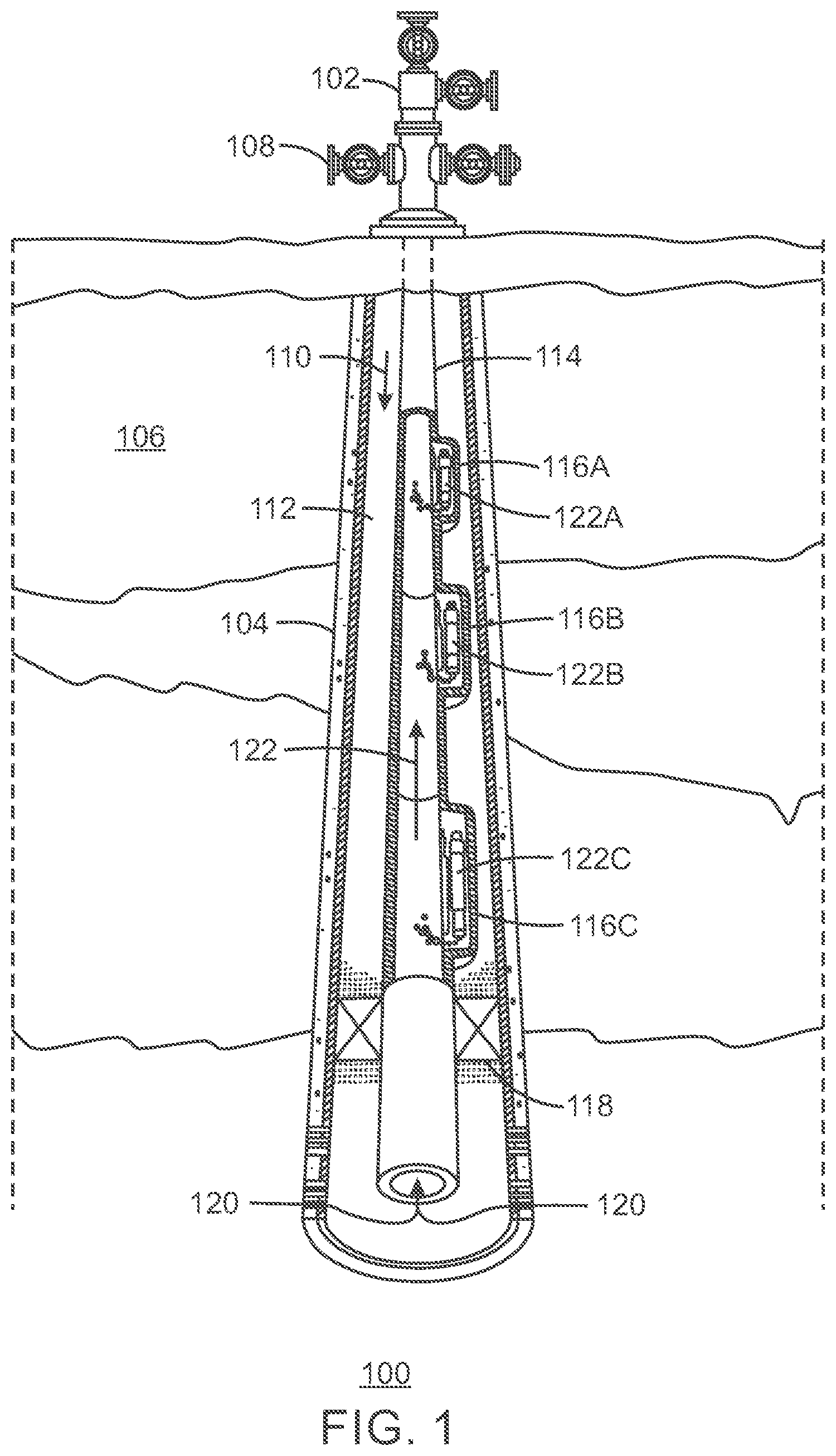
[0037] FIG. 1 is a schematic view of a well 100 including a gas lift system. The well 100 includes a wellhead 102 on top of a well casing 104 that passes through a formation 106. The wellhead 102 includes a coupling 108 for injecting compressed gas 110 into an annulus 112 of the well 100, for example, formed between the well casing 104 and production tubing 114.
[0038] The production tubing 114 includes a number of side-pocket mandrels 116A, 116B and 116C and a production packer 118. Downhole, the production packer 118 forces produced hydrocarbon fluids 120 from the formation 106 to travel up through the production tubing 114. In addition, the production packer 118 keeps the gas flow in the annulus 112 from entering the production tubing 114.
[0039] To conduct a gas lift operation, operators install gas lift valves (GLVs) 122A, 122B and 122C into the side-pocket mandrels 116A, 116B and 116C, either before deployment or wireline or slickline after deployment. Once the GLVs 122A, 122B and 122C are installed, the compressed gas 110 is injected into the annulus 112 via the coupling 108. The compressed gas 110 then travels down the annulus 112 until it reaches the side-pocket mandrels 116A, 116B and 116C. Entering the side-pocket mandrels' ports, the compressed gas 110 passes through the respective GLVs 122A, 122B and 122C and into the production tubing 114. The GLVs 122A, 122B and 122C then act as one-way valves by allowing the compressed gas 110 to flow from the annulus 112 to the production tubing 114, while preventing fluid flow in the opposite direction.
[0040] Once the compressed gas 110 enters the production tubing 114, it rises to the surface, helping to remove completion fluid from the annulus 112 and the production tubing 114, as described further with respect to FIG. 2. Moreover, once the completion fluid has been removed, the compressed gas 110 is used to help lift the hydrocarbon fluids 120 in the production tubing 114 to the surface when reservoir pressure alone is not sufficient.
[0041] FIG. 2 is a simplified schematic view showing the unloading of completion fluids from the well 100 using the gas lift system. Like numbered items are as described with respect to FIG. 1. Before start-up, the well 100 is filled with completion fluid 202, in the annulus 112 and the production tubing 114, to provide a pressure cap on the hydrocarbon fluids 120 coming up from a reservoir 204. Once the production tubing 114 is in place, the completion fluid 202 is typically removed, for example, to be replaced with the compressed gas 110 used for gas lift assist.
[0042] As shown in FIG. 2, the unloading of the completion fluid 202 is performed by injecting the compressed gas 110 into the coupling 108 that leads to the annulus 112 of the well 100. As the compressed gas 110 is forced down the annulus 112, the completion fluid 202 is forced through the GLVs 122A, 122B and 122C, and up the production tubing 114. A production line 206 is coupled to the production tubing 114, and is used to remove the completion fluid 202, which may be referenced as a produced or production fluid.
[0043] As the liquid level 208 crosses a particular GLV 122A, 122B and 122C, the compressed gas 110 enters the production tubing 114 through the GLV 122A, 122B and 122C. The compressed gas 110 creates bubbles 210 that are entrained in the completion fluid 202, which lower the density of the completion fluid 202, allowing the pressure of the compressed gas 110 to push the completion fluid 202 to the surface. As the liquid level 208 crosses a particular GLV 122A, 122B and 122C, for example, the mid-level GLV 122B, the pressure drop from the compressed gas 110 entering the production tubing 114 through the particular GLV 122B causes a next higher GLV, for example, the highest GLV 122A in the well 100, to close. When the liquid level 208 reaches the lowest GLV 122C, which is the operating valve in the well 100, the pressure drop causes the next higher GLV 122B to close, leaving only the operating valve open. Compressed gas 110 entering through the operating valve may then assist in the production of the hydrocarbon fluids 120 from the reservoir 204.
[0044] In some embodiments, the compressed gas 110 includes a gas and/or liquid mixture. For example, chemicals may also be injected into the annulus 112 to assist in the production of the hydrocarbon fluids 120 from the reservoir 204.
[0045] As described with respect to FIG. 2, ideally, only the operating valve, which is the lowest GLV 122C, will remain open once the completion fluid has been removed from the annulus 112 and the production tubing 114 via the unloading valves, which are the two highest GLVs 122A and 122B. However, in operation, it is difficult to monitor whether a particular GLV 122A, 122B, or 122C is open or closed. Moreover, the well 100 will still function even when it is not optimized. Specifically, the well 100 will still flow, albeit at a reduced production rate, even if it is receiving too much (or too little) compressed gas 110 and/or is lifting from multiple GLVs 122A-C or a GLV 122A or 122B that is shallower than the desired operating point, i.e., an unloading valve instead of the desired operating valve.
[0046] Therefore, according to embodiments described herein, one or more of the GLVs 122A, 122B and 122C within the well 100 is a power-generating GLV that uses the compressed gas 110 (or other fluid) flowing through the GLV as a motive source for generating power locally within the GLV. The generated power may then be used for a variety of downhole applications, such as operating one or more well optimization devices. For example, the generated power may be used to operate a valve position sensor. This may greatly improve the performance of the gas lift system by providing an efficient, cost-effective way to determine whether the GLV is in the open or closed position. The generated power may also be used to operate other sensors, such as pressure, temperature, and/or flow rate sensors, receive and/or store data from other devices, or communicate data to other locations within the well or the surface via wired or wireless means.
[0047] Power-Generating Gas Lift Valve
[0048] FIG. 3 is a cutaway view of a portion of the well 100 including a power-generating gas lift valve (GLV) 300 that fluidically couples the annulus 112 of the well 100 to the interior 302 of the production tubing 114. Like numbered items are as described with respect to FIGS. 1 and 2. In various embodiments, the power-generating GLV 300 replaces one or more of the GLVs 122A, 122B and 122C described with respect to FIGS. 1 and 2. In some embodiments, this includes installing the power-generating GLV 300 in the side-pocket mandrel 116 during the initial completion of the well 100. In other embodiments, this includes installing the power-generating GLV 300 in the side-pocket mandrel 116 via wireline or slickline after deployment. Moreover, in some embodiments, multiple power-generating GLVs 300 are installed, uninstalled, or replaced periodically during the lifetime of the well 100 such that the performance of the well 100 is optimized.
[0049] As shown in FIG. 3, the power-generating GLV 300 is mounted within the side-pocket mandrel 116, which is constructed as a section, or joint, of the production tubing 114 that has an oblong expansion. The power-generating GLV 300 includes a bellows 304, which provides the operational force that determines the pressure at which the power-generating GLV 300 will open and close. Depending on the installation depth of the power-generating GLV 300 in the well 100 and the pressure of the compressed gas 110, the expected backpressure may be in a range of between about 1,000 pounds per square inch (psi) to 5,000 psi.
[0050] The power-generating GLV 300 also includes an orifice 306 that allows the compressed gas 110 to flow from the annulus 112 into the power-generating GLV 300, as well as an internal nozzle 308 that allows the compressed gas to flow from the power-generating GLV 300 to the interior 302 of the production tubing 114 when the power-generating GLV 300 is in the open position, as shown in FIG. 3.
[0051] The power-generating GLV 300 includes a stem 310 and a seat 312 that prevent the compressed gas 110 within the annulus 112 from flowing through the power-generating GLV 300 to the interior 302 of the production tubing 114 when the power-generating GLV 300 is in the closed position. In addition, the power-generating GLV 300 includes a reverse-flow check valve 314 that prevents the hydrocarbon fluids 120 within the interior 302 of the production tubing 114 from flowing through the power-generating GLV 300 to the annulus 112 when the power-generating GLV 300 is in the closed position.
[0052] The power-generating GLV 300 also includes an internal chamber 316 through which the compressed gas 110 flows as it travels from the orifice 306 to the internal nozzle 308. According to embodiments described herein, a power generation device 318 is located within the internal chamber 316. The power generation device 318 is configured to convert energy from the compressed gas 110 flowing through the power-generating GLV 300 into electricity. In various embodiments, the power generation device 318 includes a rotary assembly (not shown) and an electrical generator (not shown). However, the power generation device 318 may also include any other type of device that is capable of using the compressed gas 110 as a source for power generation. Furthermore, the generated power may be stored in a power storage device (not shown), and may then be used for a variety of downhole applications, such as operating one or more well optimization devices (not shown) within the well 100. The power generation device 318 and associated equipment are described further with respect to FIGS. 4A and 4B.
[0053] The cutaway view of FIG. 3 is not intended to indicate that the power-generating GLV 300 is to include all of the components shown in FIG. 3. Further, any number of additional components may be included within the power-generating GLV 300, depending on the details of the specific implementation. For example, in the embodiment shown in FIG. 3, the power-generating GLV 300 is installed in the side-pocket mandrel 116. However, in other embodiments, the power-generating GLV 300 may be mounted in any other suitable mounting point, such as, for example, a conventional mandrel.
[0054] In various embodiments, the data collected using the power-generating GLV 300 described herein may be used to optimize the well 100. For example, the amount of the compressed gas 110 flowing into the annulus 112 may be optimized such that the hydrocarbon fluids 120 are efficiently extracted from the reservoir 204. In addition, because the compressed gas 110 used for gas lift systems is an easily-metered, single-phase fluid, expected power generation is relatively simple to predict, and the compressed gas 110 provides a steady, reliable source for power generation. Furthermore, because the power generation device 318 may cause a negligible drop in pressure, such as less than around 50 psi, the power-generating GLV 300 should not significantly increase the operating costs for the gas lift system.
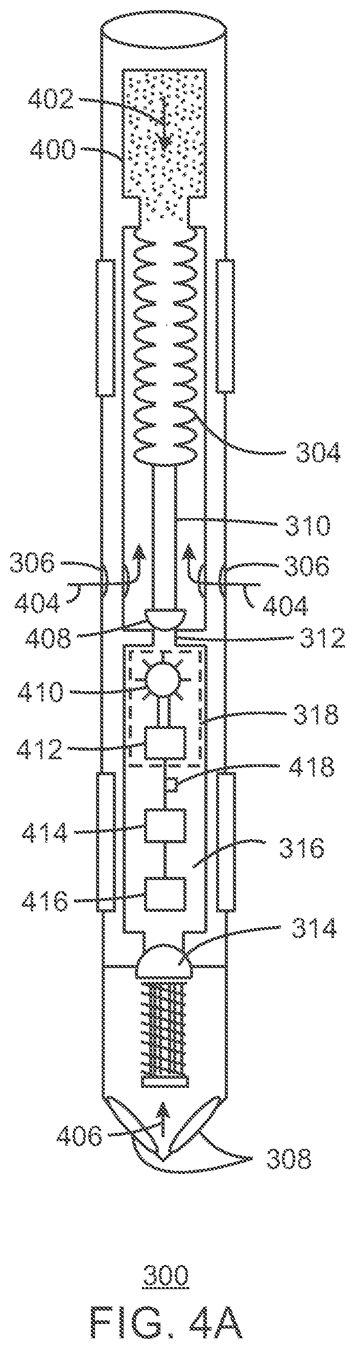
[0055] FIG. 4A is a cross-sectional view showing an exemplary embodiment of the power-generating GLV 300 in the closed position. Like numbered items are as described with respect to FIGS. 1, 2 and 3. As shown in FIG. 4A, the power-generating GLV 300 includes the spring-loaded bellows 304 and a nitrogen-charged dome 400. When the nitrogen charge pressure 402 within the dome 400 is higher than the total pressure applied to the dome 400, which is the sum of the injection pressure 404 that the compressed gas 110 applies to the bellows 304 and the production pressure 406 that the hydrocarbon fluids 120 within the interior 302 of the production tubing 114 apply to a tip 408 of the stem 310, the tip 408 of the stem 310 rests against the seat 312. This prevents the compressed gas 110 from the flowing into the internal chamber 316 of the power-generating GLV 300, thus preventing the compressed gas 110 within the annulus 112 from flowing through the power-generating GLV 300 to the interior 302 of the production tubing 114. Moreover, because the power-generating GLV 300 is in the closed position, minimal pressure is applied downward on the reverse-flow check valve 314. Therefore, the reverse-flow check valve 314 remains closed, preventing hydrocarbon fluids 120 within the interior 302 of the production tubing 114 from flowing through the power-generating GLV 300 to the annulus 112.
[0056] According to the embodiment shown in FIG. 4A, the internal chamber 316 of the power generation device 318 includes a rotary assembly 410, such as a paddlewheel or turbine, for example, coupled to an electrical generator 412, such as an AC or DC generator, for example. In addition, the power generation device 318 is connected to a power storage device 414, such as a battery, capacitor bank, thermal bank, or flywheel, for example, and a sensor 416, such as a valve position sensor, pressure sensor, temperature sensor, or flow rate sensor, for example. The operation of these components is described in more detail with respect to FIG. 4B.
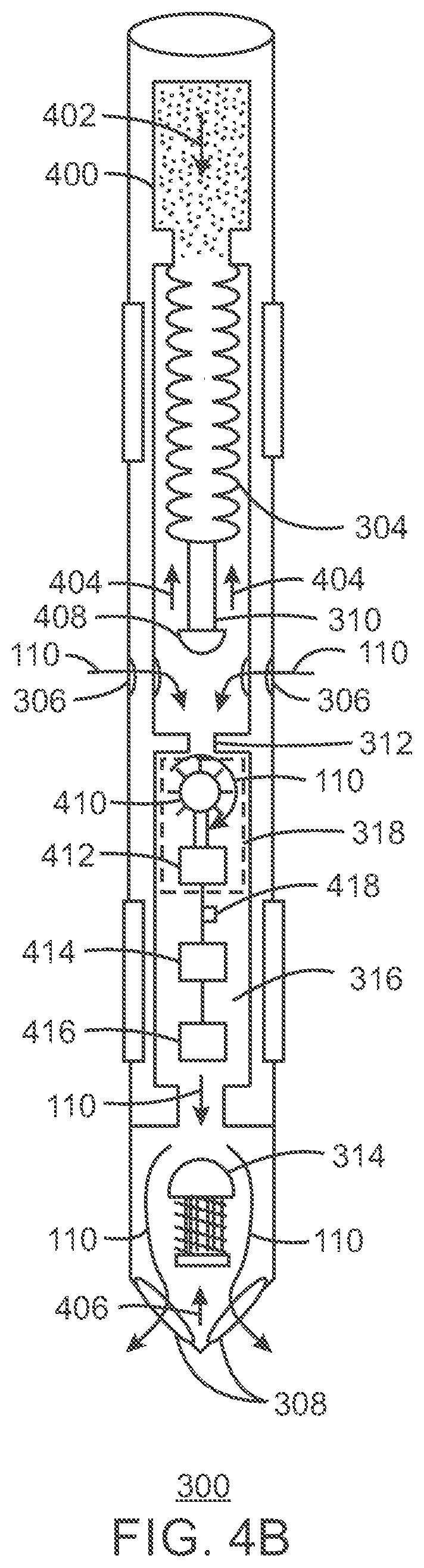
[0057] FIG. 4B is a cross-sectional view showing the exemplary embodiment of the power-generating GLV 300 in the open position. Like numbered items are as described with respect to FIGS. 1, 2, 3, and 4A. When the total pressure applied to the dome 400 is higher than the nitrogen charge pressure 402 within the dome 400, the spring-loaded bellows 304 compresses, disengaging the tip 408 of the stem 310 from the seat 312. This allows the compressed gas 110 to flow into the internal chamber 316 of the power-generating GLV 300. Moreover, the downward application of the injection pressure 404 to the reverse-flow check valve 314 also causes the reverse-flow check valve 314 to open. This allows the compressed gas 110 within the annulus 112 to flow through the power-generating GLV 300 to the interior 302 of the production tubing 114.
[0058] In various embodiments, the open position of the power-generating GLV 300 corresponds to a power generation mode of the power-generating GLV 300. Specifically, as the compressed gas 110 flows downward into the internal chamber 316 of the power-generating GLV 300, the compressed gas 110 causes the rotary assembly 410 to rotate. This provides the motive force for the generation of power by the electrical generator 412. In various embodiments, the rotary assembly 410 includes a paddlewheel, turbine, or other rotating device, for example, and the electrical generator 412 includes an AC generator or a DC generator, for example.
[0059] According to the embodiment shown in FIG. 4B, the full stream of the compressed gas 110 is used to rotate the rotary assembly 410. However, in other embodiments, a slipstream of the compressed gas 110 is diverted from the main flow path of the compressed gas 110. The slipstream of the compressed gas 110 is then used to rotate the rotary assembly 410, while the rest of the stream bypasses the rotary assembly 410. This provides an easy way to meter the rotary assembly 410 such that a suitable amount of motive force is provided to the electrical generator 412.
[0060] The generated power is then stored in the power storage device 414. The power storage device 414 may include, for example, a battery, a capacitor bank, a thermal bank, or a flywheel. In various embodiments, a switch 418 located between the electrical generator 412 and the power storage device 414 allows the power storage device 414 to disconnect from the electrical generator 412 when the power storage is maximized. For example, if the power storage device 414 is a battery, the switch 418 may prevent the battery from overcharging by automatically disconnecting the battery from the electrical generator 412 when it is fully charged.
[0061] The power stored within the power storage device 414 is then used to operate the sensor 416. The sensor 416 may include, for example, a valve position sensor configured to detect whether the power-generating GLV 300 is in the open or closed position, a pressure sensor configured to detect a pressure of fluid within the well 100, a temperature sensor configured to detect a temperature of fluid within the well 100, or a flow rate sensor configured to detect the flow rate of the compressed gas 110 through the power-generating GLV 300. The sensor 416 may also be replaced with any other device that is useful for optimizing the well 100. According to embodiments described herein, the sensor 416 and all other devices for optimizing the well 100 are generally referred to as "well optimization devices." Other exemplary well optimization devices include devices for receiving and/or storing data from other devices within the well 100, and devices for communicating data to other locations within the well 100 or the surface via wired or wireless means. Still other well optimization devices may include on-board devices for adjusting one or more gas lift flow rate or pressure regulating valves or orifices within the gas lift valve assembly. For example, an electrically powered driver for hydraulically or electrically adjusting opening size or back-pressure spring force to adjust or fine-tune gas lift valve performance. Moreover, while only one sensor 416 is shown in FIGS. 4A and 4B, any number of additional sensors (and/or other well optimization devices) may be connected to the power storage device 414. Furthermore, while the sensor 416 is to positioned within the internal chamber 316 of the power-generating GLV 300 according to the embodiment shown in FIGS. 4A and 4B, the sensor 416 (and/or other well optimization devices) may be positioned in any suitable location within the power-generating GLV 300 or the well 100.
[0062] In some embodiments, the data collected from the sensor 416 is stored within a memory device (not shown). The memory device is a well optimization device that may be powered by the power storage device 414. The memory device may include, for example, a solid state memory device, a volatile memory device, a non-volatile memory device, or a flash memory device.
[0063] In some embodiments, the data stored in the memory device and then sent to the surface using a variety of techniques. For example, in some embodiments, the power-generating GLV 300 also includes a data transmitter (not shown). The data transmitter is another well optimization device that may be powered by the power storage device 414. The data transmitter may be configured to transmit the collected data to a data receiver (not shown) located on the surface using wired or wireless means. The data transmitter may include, for example, a wireless data transmitter, a radio frequency (RF) data transmitter, or a Bluetooth data transmitter. Further, in other embodiments, pressure modulation techniques are used to send the collected data to the surface. For example, if the sensor 416 is a valve position sensor, data collected by the valve position sensor may be used to send a pressure signature of the pressure-generating GLV 300 to the surface. Pressure readings at the surface may then be used to determine whether the pressure-generating GLV 300 is in the open or closed position.
[0064] Once the data is transmitted to the surface, it may be used to optimize the well 100. For example, if the sensor 416 includes a valve position sensor, the collected data may be used to determine whether the gas lift system is operating correctly. As another example, if the sensor 416 includes a pressure, temperature, and/or flow rate sensor, the collected data may be used to adjust the pressure, temperature, and/or flow rate of the compressed gas 110 such that the hydrocarbon fluids 120 are efficiently produced from the reservoir 204.
[0065] The cross-sectional views of FIGS. 4A and 4B are not intended to indicate that the power-generating GLV 300 is to include all of the components shown in FIGS. 4A and 4B. Moreover, any number of additional components may be included within the power-generating GLV 300, depending on the details of the specific implementation. Furthermore, it is to be understood that the power-generating GLV 300 shown in FIGS. 3, 4A, and 4B is merely one exemplary embodiment of the power-generating GLV described herein, which may include any suitable type of GLV that can be designed or adapted to include a power generation device.
[0066] In various embodiments, the power-generating GLV 300 is retrievable. For example, the power-generating GLV 300 may be extracted from the side-pocket mandrel 116 (or other mounting point) using wireline, slickline, or coiled tubing, for example. In addition, existing wells may be retrofitted with new power-generating GLVs 300 using the same techniques.
[0067] Method for Generating Power within a Gas Lift Valve
[0068] FIG. 5 is a process flow diagram of a method 500 for generating power within a gas lift valve (GLV). In various embodiments, the GLV is the power-generating GLV 300 described with respect to FIGS. 3, 4A, and 4B. Moreover, in various embodiments, the GLV is implemented within a well completion as part of the gas lift system of the well, as described with respect to FIGS. 1, 2 and 3. The GLV may be mounted within a side-pocket mandrel or a conventional mandrel, and may be used to fluidically couple an annulus of the well completion to an interior of a production tubing of the well completion.
[0069] The method 500 begins at block 502, at which a fluid flowing through the GLV is used to generate power within a power generation device. The fluid may be, for example, a compressed gas that is used for the gas lift system of the well. The power generation device may be located within an internal chamber of the GLV, and may use either a full stream or a slipstream of the fluid flowing through the GLV to generate power.
[0070] In various embodiments, an open position of the GLV corresponds to a power generation mode of the GLV. When the GLV is in the open position, the fluid flows through the GLV to travel from the annulus to the interior of the production tubing.
[0071] Further, in various embodiments, the power generation device includes a rotary assembly and an electrical generator. The rotary assembly may include, for example, a paddlewheel or a turbine, and the electrical generator may include, for example, an AC generator or a DC generator. The power generation fluid, which may be a portion or all of the injection fluid, produced fluid or combination thereof, may be used to generate the power (e.g., rotate or move the paddlewheel).
[0072] The method 500 may then continue to blocks 504 and 506, which are optional (as indicated by the dotted lines in FIG. 5). At block 504, the power generated by the power generation device is stored within a power storage device. The power storage device may include, for example, a battery, a capacitor bank, a thermal bank, or a flywheel. In some embodiments, the GLV includes a switch for disconnecting the power storage device from the power generation device when power storage within the power storage device is maximized.
[0073] At block 506, the power stored within the power storage device is used to power a well optimization device. The well optimization device may include a sensor, such as a valve position sensor, a pressure sensor, a temperature sensor, or a flow rate sensor. The well optimization device may also include a memory device for storing data collected by a sensor or other well optimization device. The well optimization device may further include a data transmitter for transmitting data collected by a sensor or other well optimization device to a data receiver. In various embodiments, the data that is collected, stored, and/or transmitted by the well optimization device(s) are used to optimize the well completion.
[0074] The process flow diagram of FIG. 5 is not intended to indicate that the steps of the method 500 are to be executed in any particular order, or that all of the steps of the method 500 are to be included in every case. Further, any number of additional steps not shown in FIG. 5 may be included within the method 500, depending on the details of the specific implementation.
[0075] As may be appreciated, performing hydrocarbon operations may include injecting various fluids into a well and removing various fluids from the well. The fluid flow is typically involves pressure changes. The injected fluids may be provided at various pressures, which are controlled at the wellhead and may involve different injection fluids. As noted above, one type of hydrocarbon operation is an artificial lift operation, which includes injecting a fluid into the wellbore, which is an injection fluid (e.g., a high-pressure fluid, such as in the range between 800 psi and 2500 psi). The injection fluid may be injected through a conduit or injected into the production tubing via the casing annulus. Then, the injection fluid may pass through one or more GLVs. The GLVs provide a fluid pathway for a designed volume of injection fluid, which may be an injection gas to enter the production tubing, as an example. Then, the resulting fluid is produced through the wellbore and the wellhead. The injection fluid is configured to decrease the density of the fluid column, decrease the backpressure on the production zones in the subsurface formation.
[0076] The injection fluid or the produced fluid may be used by the GLV to generate power, as noted above. In one or more embodiments, the injection fluid is used, as it is at a higher pressure and may be controlled more than the produced fluid. As an example, a method for generating power within wellbore, the method comprising: passing an injection fluid into a wellbore in fluid communication with a subsurface formation; mixing the injection fluid with formation fluids to form a produced fluid; flowing the produced fluid through the wellbore to a wellhead; generating power by passing a power generation fluid through a gas lift valve (GLV); and wherein the power generation fluid is one of a portion of the injection fluid, a portion of the produced fluid or combination thereof. The injected fluid in the method may be a compressed gas and may be passed into an annulus within the wellbore between a well casing and a production tubing.
[0077] In another embodiment, a hydrocarbon system is described. This hydrocarbon system may include a wellhead; a wellbore in fluid communication with the wellhead and a subsurface formation; well casing disposed within the wellbore, wherein the casing provides one or more fluid flow paths from the subsurface formation to the wellhead; a gas lift valve (GLV) within the wellbore, wherein the GLV comprises a power generation device that uses a fluid flowing through the GLV to generate power. The hydrocarbon system may also include a coupling configured to inject a compressed gas into the wellbore, wherein the compressed gas is passed through the GLV to generate power, and wherein the production tubing includes one or more side-pocket mandrels and a production packer, wherein one of the one or more side-packet mandels includes the GLV. Furthermore, the hydrocarbon system may include a GLV that has a power generation device configured to use the fluid flowing through the GLV to generate power; a power storage device configured to store the power generated by the power generation device; and a well optimization device configured to use the power stored within the power storage device, to collect data from one or more sensors associated with the wellbore operations, to store the data from the sensor, and transmit the data from the sensor.
[0078] In yet other embodiments, the produced fluid and/or the injection fluid may be used to generate power. Electricity generation methods involving a mass flow (e.g., turbine and/or expander) typically generate proportionally to the throughput. Accordingly, the amount of fluid may be adjusted to the power needs of the equipment being supported. As such, if a small amount of power (e.g., 1 to 100 milliWatts (mW) for a sensor), then the mass flow and may only need a slip stream to generate the power for the sensor (e.g., slip stream of the injected fluid or produced fluid). By only using a slip stream, the pressure drop may be minimized as compared to the pressure drop from using the entire stream, which may negatively impact the gas lift operations in the hydrocarbon system (e.g., by limiting the amount of gas that you can push through a valve). To balance the power, the GLV may be configured to balance the well optimization power requirement and determine how much mass flow needed to create the optimization power requirement. This may be obtained by creating and/or adjusting the slip stream exhausted to the tubing or may be based on the full stream that is passing through the GLV. Accordingly, by including functionality to adjust the stream used in the power generation, the GLV may be adjusted to provide more or less power to optimize the operation of the hydrocarbon system. Accordingly, the hydrocarbon system may be configured to communicate from the GLV or a sensor to a control unit at the surface of the wellbore. The data from the sensor may be used to adjust the operations. The control unit may be used to adjust the injection rate, or adjust the operation of one or more of the GVLs.
[0079] In yet other embodiments, the GLVs may be used for well optimization, which may be used to change the operation of the hydrocarbon system. As an example, for a gas lift operations, adjustments may be made to adjust the gas lift rate so that the injection fluid is provided at an optimal amount for production. If gas lift rate is low (e.g., too low a volume of gas), then the hydrostatic gradient is higher and the reservoir pressure is higher than necessary, and the well produces is less. If the gas lift rate is too high, then the friction pressure in the tubing is higher than necessary and the well produces less. Any additional information from downhole sensors (e.g., pressure and/or injection rates at each valve) may be used to determine whether the optimal rates or settings has be obtained or whether adjustments are needed to enhance the operations. Accordingly, the hydrocarbon system may include a sensor and control unit that may be configured to communicate between the GLV, within the wellbore, sensor within the wellbore and the control unit at the surface of the wellbore. The data may be used to adjust the operations. The control unit may be used to adjust the injection rate, or adjust the operation of one or more of the GVLs.
[0080] In one or more embodiments, the present techniques may be susceptible to various modifications and alternative forms, such as the following embodiments as noted in paragraphs A to HH:
A. A gas lift valve (GLV), comprising a power generation device that uses a fluid flowing through the GLV to generate power. B. The GLV of paragraph A, wherein the power generation device is located within an internal chamber of the GLV. C. The GLV of paragraph A, wherein the fluid flowing through the GLV is a compressed gas that is used for a gas lift system within a well. D. The GLV of paragraph A, wherein the power generation device uses a full stream of the fluid flowing through the GLV to generate the power. E. The GLV of paragraph A, wherein the power generation device uses a slipstream of the fluid flowing through the GLV to generate the power. F. The GLV of paragraph A, wherein an open position of the GLV corresponds to a power generation mode of the GLV. G. The GLV of paragraph F, wherein the fluid flows through the GLV to travel from an annulus of a well to an interior of a production tubing of the well when the GLV is in the open position. H. The GLV of paragraph A, wherein the power generation device comprises a rotary assembly and an electrical generator. I. The GLV of paragraph H, wherein the rotary assembly comprises a paddlewheel or a turbine. J. The GLV of paragraph H, wherein the electrical generator comprises an AC generator or a DC generator. K. The GLV of paragraph A, comprising a power storage device for storing the power generated by the power generation device. L. The GLV of paragraph K, wherein the power storage device comprises at least one of a battery, a capacitor bank, a thermal bank, or a flywheel. M. The GLV of paragraph K, comprising a switch for disconnecting the power storage device from the power generation device when power storage within the power storage device is maximized. N. The GLV of paragraph A, wherein the power generated by the GLV is used to power a well optimization device. O. The GLV of paragraph N, wherein the well optimization device comprises a sensor. P. The GLV of paragraph O, wherein the sensor comprises at least one of a valve position sensor, a pressure sensor, a temperature sensor, or a flow rate sensor. Q. The GLV of paragraph O, wherein the well optimization device comprises a memory device for storing data collected by a sensor or other well optimization device. R. The GLV of paragraph O, wherein the well optimization device comprises a data transmitter for transmitting data collected by a sensor or other well optimization device to a data receiver. S. The GLV of paragraph A, wherein the GLV is mounted within a side-pocket mandrel or a conventional mandrel. T. The GLV of paragraph A, wherein the GLV is an operating valve or an unloading valve. U. A method for generating power within a gas lift valve (GLV), comprising using a fluid flowing through the GLV to generate power within a power generation device. V. The method of paragraph U, wherein the power generation device is located within an internal chamber of the GLV. W. The method of paragraph U, wherein the fluid flowing through the GLV is a compressed gas that is used for a gas lift system within a well. X. The method of paragraph U, wherein the power generation device comprises a rotary assembly and an electrical generator. Y. The method of paragraph U, comprising storing the power generated by the power generation device within a power storage device. Z. The method of paragraph Y, comprising disconnecting the power storage device from the power generation device using a switch when power storage within the power storage device is maximized. AA. The method of paragraph U, comprising using the power generated by the GLV to power a well optimization device. BB. The method of paragraph AA, wherein the well optimization device comprises a sensor. CC. The method of paragraph U, wherein the well optimization device comprises a memory device for storing data collected by a sensor or other well optimization device. DD. The method of paragraph U, wherein the well optimization device comprises a data transmitter for transmitting data collected by a sensor or other well optimization device to a data receiver. EE. A well completion, comprising a gas lift valve (GLV) that fluidically couples an annulus of the well completion to an interior of a production tubing of the well completion, wherein the GLV comprises: a power generation device configured to use a compressed gas flowing through the GLV to generate power; a power storage device configured to store the power generated by the power generation device; and a well optimization device configured to use the power stored within the power storage device to collect, store, or transmit data about the well completion. FF. The well completion of paragraph EE, wherein the power generation device is located within an internal chamber of the GLV, and wherein the compressed gas flows through the internal chamber to travel from the annulus to the interior of the production tubing when the GLV is in an open position. GG. The well completion of paragraph EE, wherein the power generation device comprises a rotary assembly and an electrical generator. HH. The well completion of paragraph EE, wherein the well optimization device comprises at least one of a sensor, a memory device, or a data transmitter.
[0081] While the present techniques may be susceptible to various modifications and alternative forms, the examples discussed above have been shown only by way of example. However, it should again be understood that the present techniques are not intended to be limited to the particular examples disclosed herein. Indeed, the present techniques include all alternatives, modifications, and equivalents falling within the true spirit and scope of the appended claims.
* * * * *
D00000
D00001
D00002
D00003
D00004
D00005
D00006
XML
uspto.report is an independent third-party trademark research tool that is not affiliated, endorsed, or sponsored by the United States Patent and Trademark Office (USPTO) or any other governmental organization. The information provided by uspto.report is based on publicly available data at the time of writing and is intended for informational purposes only.
While we strive to provide accurate and up-to-date information, we do not guarantee the accuracy, completeness, reliability, or suitability of the information displayed on this site. The use of this site is at your own risk. Any reliance you place on such information is therefore strictly at your own risk.
All official trademark data, including owner information, should be verified by visiting the official USPTO website at www.uspto.gov. This site is not intended to replace professional legal advice and should not be used as a substitute for consulting with a legal professional who is knowledgeable about trademark law.