Cross-lamination Timber (clt) Joint
SCHNEIDER; Johannes ; et al.
U.S. patent application number 17/036961 was filed with the patent office on 2021-04-01 for cross-lamination timber (clt) joint. This patent application is currently assigned to Katerra Inc.. The applicant listed for this patent is Katerra Inc.. Invention is credited to Robert MALCZYK, Johannes SCHNEIDER.
| Application Number | 20210095479 17/036961 |
| Document ID | / |
| Family ID | 1000005137789 |
| Filed Date | 2021-04-01 |


| United States Patent Application | 20210095479 |
| Kind Code | A1 |
| SCHNEIDER; Johannes ; et al. | April 1, 2021 |
CROSS-LAMINATION TIMBER (CLT) JOINT
Abstract
A Cross-Laminated Timber (CLT) joint is provided that can be used to connect at least two CLT components such as CLT panels. The CLT panel can be prefabricated and pre-assembled, and can be easily and quickly installed. The CLT joint includes a first CLT component and a second CLT component. The first CLT component includes a recessed channel. The second CLT component includes a grooved extension. The grooved extension and the recessed channel have complimentary patterns. The grooved extension is configured to nest within the recessed channel. The CLT panel includes a first CLT side and a second CLT side. The first CLT side includes a recessed channel. The second CLT side may be opposite the first CLT side and includes a grooved extension. The grooved extension and the recessed channel have complimentary patterns. A CLT panel system is also provided comprising a plurality of CLT panels.
| Inventors: | SCHNEIDER; Johannes; (Vancouver, CA) ; MALCZYK; Robert; (Vancouver, CA) | ||||||||||
| Applicant: |
|
||||||||||
|---|---|---|---|---|---|---|---|---|---|---|---|
| Assignee: | Katerra Inc. Menlo Park CA |
||||||||||
| Family ID: | 1000005137789 | ||||||||||
| Appl. No.: | 17/036961 | ||||||||||
| Filed: | September 29, 2020 |
Related U.S. Patent Documents
| Application Number | Filing Date | Patent Number | ||
|---|---|---|---|---|
| 62907811 | Sep 30, 2019 | |||
| Current U.S. Class: | 1/1 |
| Current CPC Class: | E04F 13/0898 20130101; E04F 2201/0115 20130101; E04F 13/0894 20130101 |
| International Class: | E04F 13/08 20060101 E04F013/08 |
Claims
1. A Cross-Laminated Timber (CLT) joint comprising: a first CLT component including a recessed channel; and a second CLT component including a grooved extension, the grooved extension and the recessed channel having complimentary patterns wherein the grooved extension is configured to nest within the recessed channel.
2. The CLT joint of claim 1, wherein the grooved extension has a stepped down profile.
3. The CLT joint of claim 1, wherein the grooved extension includes at least one seal.
4. The CLT joint of claim 3, wherein the at least one seal is grooved and set into the grooved extension.
5. The CLT joint of claim 1, wherein the recessed channel and the grooved extension are configured to create a space between the first CLT component and the second CLT component when the grooved extension is nested in the recessed channel.
6. The CLT joint of claim 3, wherein the seal is part of a membrane that is adhered to the grooved extension.
7. A Cross-Laminated Timber (CLT) panel comprising: a first CLT side including a recessed channel; and a second CLT side including a grooved extension, the grooved extension and the recessed channel having complimentary patterns.
8. The CLT panel of claim 7 further comprising a third CLT side including a second recessed channel and a fourth CLT side including a second grooved extension, the second grooved extension and the second recessed channel having complimentary patterns.
9. The CLT panel of claim 7, wherein the grooved extension has a stepped down profile.
10. The CLT panel of claim 7, wherein the panel is comprised of pieces of dimensional lumber glued and stacked in multiple crosswise layers.
11. The CLT panel of claim 10, wherein the at least one seal is grooved and set into the grooved extension.
12. A Cross-Laminated Timber (CLT) panel system comprising: a first CLT panel including a first CLT horizontal side including a first grooved extension and a first CLT vertical side including a first recessed channel; a second CLT panel including a second CLT horizontal side including a second grooved extension and second CLT vertical side including a third grooved extension; a third CLT panel including a third CLT horizontal side including a second recessed channel and a third CLT vertical side including a third recessed channel; and a fourth CLT panel including a fourth CLT horizontal side including a fourth recessed channel and a fourth CLT vertical side including a fourth grooved extension; the first grooved extension configured to connect with the second recessed channel; the first recessed channel configured to connect with the third grooved extension; the second grooved extension configured to connect with the fourth recessed channel; the third recessed channel configured to connect with the fourth grooved extension.
13. The CLT panel system of claim 12, wherein the first grooved extension and the second recessed channel are configured to be a tongue and groove type connection.
14. The CLT panel system of claim 12, wherein the second grooved extension and the fourth recessed channel are configured to be a tongue and groove type connection.
15. The CLT panel system of claim 12, wherein the first recessed channel and the third grooved extension are configured to be a tongue and groove type connection.
16. The CLT panel system of claim 12, wherein the third recessed channel and the fourth grooved extension are configured to be a tongue and groove type connection.
17. The CLT panel system of claim 12, wherein the first grooved extension and the second groove extension each have a stepped down profile.
18. The CLT panel system of claim 12, wherein the second CLT vertical side and the fourth CLT vertical side each include at least one seal.
19. The CLT panel system of claim 12, wherein the first grooved extension and the second grooved extension each include at least one seal.
20. The CLT panel system of claim 19, wherein the at least one seal is grooved and set into the first grooved extension and the second grooved extension.
21. A method of connecting a CLT panel system comprising: receiving a first CLT panel, a second CLT panel, a third CLT panel, and a fourth CLT panel, wherein each panel may include: a first grooved extension, a first recessed channel, a second grooved extension, and a second recessed channel; connecting the second CLT panel to the first CLT panel by inserting a second grooved extension of the second CLT panel into a second recessed channel of the first CLT panel; connecting the third CLT panel to the first CLT panel by inserting a first grooved extension of the first CLT panel into a first recessed channel of the third CLT panel; connecting the fourth CLT panel to the third CLT panel and the second CLT panel by inserting a second grooved extension of the fourth CLT panel into a second recessed channel of the third CLT panel and inserting a first grooved extension of the second CLT panel into a first recessed channel of the fourth CLT panel.
Description
CROSS REFERENCE TO RELATED APPLICATION
[0001] This application claims the benefit of U.S. Provisional Application No. 62/907,811 filed on Sep. 30, 2019 for CLT Joint, which is incorporated by reference as if fully set forth.
FIELD OF INVENTION
[0002] The present invention relates generally to the art of Cross-Lamination Timber (CLT) construction, and more specifically to a CLT joint, a CLT panel, and a CLT panel system.
BACKGROUND
[0003] Cross-Laminated Timber or CLT is a pre-fabricated, engineered wood building material with unique and often superior building, aesthetic, environmental, and cost attributes. CLT wood panels are made by pressing perpendicular layers of lumber together with a layer of formaldehyde-free adhesive. The fusion of orthogonal wood layers is what gives CLT biaxial strength, durability, and stability. CLT can serve as a system-based approach for floors, walls, and roofs to form a high-performance, sustainable, and beautiful mass timber building of virtually any type.
[0004] CLT requires less energy to produce than other building materials such as steel and concrete and is made from renewable material. CLT panels may be prefabricated and are also lighter than panels made from other material such as steel, thereby reducing design costs of the building. CLT panels may be connected together to create the floor, wall, or roof. CLT panels may be connected via metal extrusions attached to the panels. However, metal extrusions can be heavy, costly, and time consuming.
SUMMARY
[0005] A Cross-Laminated Timber (CLT) joint is provided that can be used to connect at least two CLT components such as CLT panels. The CLT joint connects CLT components without metal extrusions or connectors. The CLT panel can be prefabricated and pre-assembled, and can be easily and quickly installed. The CLT joint includes a first CLT component and a second CLT component. The first CLT component includes a recessed channel. The second CLT component includes a grooved extension. The grooved extension and the recessed channel have complimentary patterns. The grooved extension is configured to nest within the recessed channel.
[0006] The CLT panel includes a first CLT side and a second CLT side. The first CLT side includes a recessed channel. The second CLT side may be opposite the first CLT side and includes a grooved extension. The grooved extension and the recessed channel have complimentary patterns.
[0007] A CLT panel system is also provided comprising a plurality of CLT panels.
BRIEF DESCRIPTION OF THE DRAWINGS
[0008] The foregoing summary, as well as the following detailed description will be better understood when read in conjunction with the appended drawings. For the purpose of illustration, there is shown in the drawings different embodiments. It should be understood, however, that the teachings are not limited to the precise CLT joint, CLT panel, and CLT panel system arrangement shown.
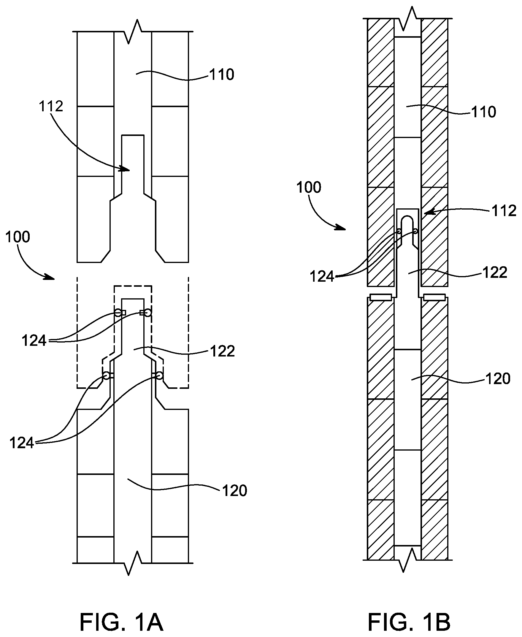
[0009] FIG. 1A is a cross-section view of a first embodiment of a CLT joint.
[0010] FIG. 1B is a cross-section view of a second embodiment of a CLT joint.
[0011] FIG. 2 is a perspective view of a CLT panel.
[0012] FIG. 3A is a first embodiment of an elevation view of the CLT panel.
[0013] FIG. 3B is a second embodiment of an elevation view of the CLT panel.
[0014] FIG. 4 is a perspective view of a section of a CLT panel system.
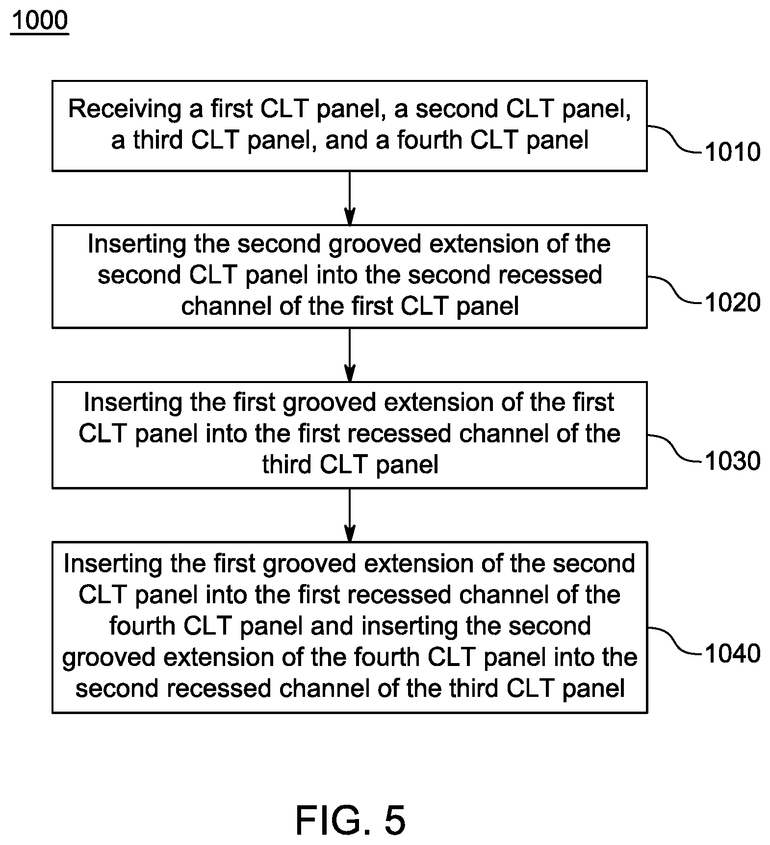
[0015] FIG. 5 is a flow chart of a method of connecting a CLT panel system.
DETAILED DESCRIPTION
[0016] A Cross-Laminated Timber (CLT) joint is provided. The CLT joint connects two or more CLT components together. CLT is a building material made from many pieces of dimensional lumber glued and stacked in multiple crosswise layers. CLT is a favored building component because it is made from strong and sustainable material. Moreover, it is lighter and cheaper than alternative building materials such as steel or aluminum. The CLT joint provides an efficient and cost effective connection of two or more CLT components without using material such as steel or aluminum.
[0017] FIG. 1A is a cross-section view of a first embodiment of a CLT joint 100. The CLT joint 100 includes a first CLT component 110 and a second CLT component 120. The first CLT component 110 includes a recessed channel 112. The recessed channel 112 may be cut into the first CLT component 110. The second CLT component 120 includes a grooved extension 122. The end of the CLT component 120 may be cut to form the grooved extension 122. The grooved extension 122 may be a step down design as shown in FIG. 1A. The grooved extension 122 design and the recessed channel 112 design are complimentary so that the first CLT component 110 and the second CLT component 120 may connect. For instance, the recessed channel 112 may have a step down design that matches the step down design of the grooved extension 122. The recessed channel 112 and the grooved extension 122 connect CLT components 110, 120 with little to no excess material.
[0018] The grooved extension 122 may also include at least one seal 124. The seals 124 may be grooved and set into the grooved extension 122. Alternatively, the seals 124 may be part of a membrane that is adhered to the grooved extension 122. The seals 124 may be made from an elastic material which allows the seals 124 to compress when the grooved extension 122 is nested in the recessed channel 112. The seals 124 may be used to create a tight fit between the recessed channel 112 and the grooved extensions 122. The seals 124 may also prevent water and air from entering the joint 100.
[0019] The design and fit of the recessed channel 112 and the grooved extension 122 may create space between the first CLT component 110 and the second CLT component 120 when the grooved extension 122 is nested in the recessed channel 112. The space allows movement and permits expansion and contraction of the first CLT component 110 and the second CLT component 120.
[0020] FIG. 1B is a cross-section view of a second embodiment of a CLT joint 100. FIG. 1B shows a CLT joint 100 wherein the recessed channel 112 has a U-shaped design that is complimentary to the step down design of the grooved extension 122. As shown in FIG. 1B, the grooved extension 122 and the seals 124 may fit into a complimentary design of a recessed channel 112 that has a U-shape.
[0021] FIG. 2 is a perspective view of a CLT panel 200. The CLT panel 200 is comprised of pieces of dimensional lumber glued and stacked in multiple crosswise layers. The CLT panel 200 includes a first CLT side 210 and a second CLT side 220. The first CLT side 210 and second CLT side 220 may be on opposite ends of the CLT panel 200. The first CLT side 210 includes a recessed channel 112 (not visible in FIG. 2). The second CLT side 220 includes a grooved extension 122. The recessed channel 112 and grooved extension 122 include the details and embodiments previously discussed.
[0022] FIG. 3A is a first embodiment of an elevation view of the CLT panel 200. FIG. 3A shows the first CLT side 210 including the recessed channel 112 and the second CLT side 220 including the grooved extension 122. FIG. 3A shows a recessed channel 112 that has a step down design in the first CLT side 210.
[0023] FIG. 3B is a second embodiment of an elevation view of the CLT panel 200. FIG. 3B shows the first CLT side 210 including the recessed channel 112 and the second CLT side 220 including the grooved extension 122. FIG. 3B shows a recessed channel 112 that has a U-shaped design in the first CLT side 210.
[0024] The recessed channel 112 in the first CLT side 210 and the grooved extension 122 in the second CLT side 220 allow the CLT panel 200 to connect to other CLT panels 200. The recessed channel 112 is configured to connect with a grooved extension 122 of an adjacent CLT panel 200. The grooved extension 122 is configured to connect with a recessed channel 112 of an adjacent CLT panel 200. CLT panels 200 may connect to each other via the CLT joint 100 previously discussed.
[0025] Referring back to FIG. 2, the CLT panel 200 may include a third CLT side 230 and a fourth CLT side 240. The third CLT side 230 may include a second recessed channel 232. The fourth CLT side 240 may include a second grooved extension 242. The second grooved extension 242 and the second recessed channel 232 have complimentary patterns. The second grooved extension 242 and second recessed channel 232 have designs that allow the second grooved extension 242 to nest in the second recessed channel 232. Like the recessed channel 112 and the grooved extension 122, the second recessed channel 232 and the second grooved extension 242 may connect with adjacent CLT panels 200. The second recessed channel 232 is configured to connect with a second grooved extension 242 of an adjacent CLT panel 200. The second grooved extension 242 is configured to connect with a second recessed channel 232 of an adjacent CLT panel 200.
[0026] The CLT panel 200 can be prefabricated and shipped to a job site. Once at the job site, the CLT panels 200 can be quickly and easily installed. The CLT panels 200, which can connect to each other without steel or aluminum connectors, may be lighter and cheaper than panels that require alternative methods of connection.
[0027] FIG. 4 is a perspective view of a section of a CLT panel system 300. The CLT panel system 300 comprises a plurality of CLT panels 200. Each CLT panel includes the details and embodiments previously discussed. The CLT panels 200 of the CLT panel system 300 connect together to form a structure such as a wall, floor, or roof. FIG. 4 illustrates an exemplary CLT panel system 300 with four CLT panels 200. FIG. 4 shows a top left portion of a first CLT panel 200a, a top right portion of a second CLT panel 200b, a bottom left portion of a third CLT panel 200c, and a bottom right portion of a fourth CLT panel 200d. The four CLT panel system 300 shows how a plurality of CLT panels 200 connect together.
[0028] The first CLT panel 200a connects to the second CLT panel 200b by inserting the second grooved extension 242b of the second CLT panel 200b into the second recessed channel 232a of the first CLT panel 200a. The second grooved extension 242b of the second CLT panel 200b connects with the second recessed channel 232a of the first CLT panel 200a thereby connecting the first CLT panel 200a with the second CLT panel 200b.
[0029] The first CLT panel 200a connects to the third CLT panel 200c by inserting the grooved extension 122a of the first CLT panel 200a into the recessed channel 112c of the third CLT panel 200c. The grooved extension 122a of the first CLT panel 200a connects with the recessed channel 112c of the third CLT panel 200c thereby connecting the first CLT panel 200a with the third CLT panel 200c.
[0030] The fourth CLT panel 200d connects to the third CLT panel 200c by inserting the second grooved extension 242d of the fourth CLT panel 200d into the second recessed channel 232c of the third CLT panel 200c. The second grooved extension 242d of the fourth CLT panel 200d connects with the second recessed channel 232c of the third CLT panel 200c thereby connecting the fourth CLT panel 200d with the third CLT panel 200c.
[0031] The second CLT panel 200b connects with the fourth CLT panel 200d by inserting the grooved extension 122b of the second CLT panel 200b into the recessed channel 112d of the fourth CLT panel 200d. The grooved extension 122b of the second CLT panel 200b connects with the recessed channel 112d of fourth CLT panel 200d thereby connecting the second CLT panel 200b with the fourth CLT panel 200d.
[0032] Any additional CLT panels 200 may connect in similar fashion. As shown in FIG. 4, the sides of the CLT panels 200a-d may also include seals 310. The seals 310 may be nailed, screwed, or adhered to the sides. The seals may be an expandable foam sealing. The seals 310 may compress when the CLT panels 200a-d are connected to prevent water and air from entering the joints between panels 200a-d.
[0033] FIG. 5 is a flow chart of a method of connecting a CLT panel system 1000. The method of connecting an exemplary four CLT panel 200a-d CLT panel system 300 can be carried out according to the method 1000 described in FIG. 5 and described below.
[0034] In step 1010, a first CLT panel 200a, a second CLT panel 200b, a third CLT panel 200c, and a fourth CLT panel 200d are received. Each CLT panel 200a-d may include a first grooved extension 122, a first recessed channel 112, a second grooved extension 242, and a second recessed channel 232. The panels 200a-d may also include seals 124, 310 as previously described.
[0035] In step 1020, the first CLT panel 200a and the second CLT panel 200b are connected by inserting the second grooved extension 242b of the second CLT panel 200b into the second recessed channel 232a of the first CLT panel 200a.
[0036] In step 1030, the third CLT panel 200c and the first CLT panel 200a are connect by inserting the first grooved extension 122a of the first CLT panel 200a into the first recessed channel 112c of the third CLT panel 200c.
[0037] In step 1040, the fourth CLT panel 200d is connected to the third CLT panel 200c and the second CLT panel 200b by inserting the second grooved extension 242d of the fourth CLT panel 200d into the second recessed channel 232c of the third CLT panel 200c and inserting the first grooved extension 122b of the second CLT panel 200b into the first recessed channel 112d of the fourth CLT panel 200d.
[0038] Having thus described in detail a preferred selection of embodiments of the present invention, it is to be appreciated and will be apparent to those skilled in the art that many physical changes could be made to the CLT joint, CLT panel, and CLT panel system without altering the inventive concepts and principles embodied therein. The present embodiments are therefore to be considered in all respects as illustrative and not restrictive, the scope of the invention being indicated by the appended claims rather than by the foregoing description, and all changes which come within the meaning and range of equivalency of the claims are therefore to be embraced therein.
* * * * *
D00000
D00001
D00002
D00003
D00004
D00005
XML
uspto.report is an independent third-party trademark research tool that is not affiliated, endorsed, or sponsored by the United States Patent and Trademark Office (USPTO) or any other governmental organization. The information provided by uspto.report is based on publicly available data at the time of writing and is intended for informational purposes only.
While we strive to provide accurate and up-to-date information, we do not guarantee the accuracy, completeness, reliability, or suitability of the information displayed on this site. The use of this site is at your own risk. Any reliance you place on such information is therefore strictly at your own risk.
All official trademark data, including owner information, should be verified by visiting the official USPTO website at www.uspto.gov. This site is not intended to replace professional legal advice and should not be used as a substitute for consulting with a legal professional who is knowledgeable about trademark law.