Full-face Mask
SHIUE; Chih-Cheng
U.S. patent application number 17/032594 was filed with the patent office on 2021-04-01 for full-face mask. The applicant listed for this patent is QBAS CO., LTD.. Invention is credited to Chih-Cheng SHIUE.
| Application Number | 20210094662 17/032594 |
| Document ID | / |
| Family ID | 1000005118497 |
| Filed Date | 2021-04-01 |


View All Diagrams
| United States Patent Application | 20210094662 |
| Kind Code | A1 |
| SHIUE; Chih-Cheng | April 1, 2021 |
FULL-FACE MASK
Abstract
A full-face mask including a mask body, a breathing tube, an isolation support portion, and a first partition is provided. The mask body includes a lens portion and a soft portion, the soft portion fits a user's face to form an inner space. The breathing tube is disposed above the mask body and is connecting with the inner space. The isolation support portion is disposed in the inner space to define an upper space and a lower space which are connected with each other. A first partition is disposed in the lower space and includes an intake valve. The lower space is defined with a proximal space and a distal space. When the user inhales, the clean air passes through the intake valve into the proximal space. Thus, the user could effectively breathe, exhale and/or isolated from leakage water to avoid danger.
| Inventors: | SHIUE; Chih-Cheng; (Taipei, TW) | ||||||||||
| Applicant: |
|
||||||||||
|---|---|---|---|---|---|---|---|---|---|---|---|
| Family ID: | 1000005118497 | ||||||||||
| Appl. No.: | 17/032594 | ||||||||||
| Filed: | September 25, 2020 |
Related U.S. Patent Documents
| Application Number | Filing Date | Patent Number | ||
|---|---|---|---|---|
| 62906925 | Sep 27, 2019 | |||
| Current U.S. Class: | 1/1 |
| Current CPC Class: | B63C 2011/165 20130101; B63C 11/16 20130101 |
| International Class: | B63C 11/16 20060101 B63C011/16 |
Foreign Application Data
| Date | Code | Application Number |
|---|---|---|
| May 22, 2020 | TW | 109117092 |
Claims
1. A full-face mask being wearable on a user's face, comprising: a mask body, comprising a lens portion and a soft portion connected to each other, the soft portion is configured to fit the user's face to form an inner space thereof; a breathing tube, being disposed above the mask body and connected with the inner space for the user to inhale clean air; an isolation support portion, being disposed in the inner space to define an upper space and a lower space thereof, wherein the upper space is connected with the lower space; and a first partition, being disposed in the lower space to define a proximal space and a distal space thereof, further comprising an intake valve, whereby the clean air enters the proximal space through the intake valve when the user inhales the clean air; wherein the breathing tube is configured to connect with the proximal space of the lower space, whereby the dirty air exhaled from the user leave the proximal space through the breathing tube.
2. The full-face mask of claim 1, wherein the first partition is shaped to allow the intake valve to be close to and aimed at the user's nostril.
3. The full-face mask of claim 1, wherein the intake valve is a constantly open intake valve.
4. The full-face mask of claim 1, wherein the first partition further comprises an exhaust valve which is disposed below the intake valve to further discharge the dirty air exhaled from the user.
5. The full-face mask of claim 1, further comprising a second partition which is disposed in the distal space to define a guide space and a temporary storage space of the distal space.
6. The full-face mask of claim 5, wherein the lens portion further comprises a guide opening which is connected with the temporary storage space.
7. The full-face mask of claim 5, further comprising at least one one-way valve which is disposed in the temporary storage space to discharge water or the dirty air exhaled from the user.
8. The full-face mask of claim 1, further comprising a channel and a splitter, wherein the channel is formed where the lens portion connects to the soft portion, and the splitter is disposed in the channel to prevent the circulation of air flowing from a lower end of the channel to the breathing tube.
Description
CROSS-REFERENCES TO RELATED APPLICATIONS
[0001] This application claims priorities to U.S. Provisional Patent Application No. 62/906,925 filed on Sep. 27, 2019 and the present invention claims priority under 35 U.S.C. .sctn. 119 Taiwan Patent Application No. 109117092 filed on May 22, 2020, where are hereby incorporated by reference in their entirety.
BACKGROUND OF THE INVENTION
Field of the Invention
[0002] The present invention provides a full-face mask for underwater activities. In particular, it provides a full-face mask for snorkeling which can improve safety.
Descriptions of the Related Art
[0003] When the full-face mask is worn, it covers the eyes, the nose and the mouth of the user at the same time so that the user can naturally breathe with the nose or the mouth, which is close to the breathing habit in general life.
[0004] At present, the intake valves of the full-face masks on the market are mostly disposed on both sides of the isolation portion. The intake valve of the full-face mask is close to the user's cheek after the wearing. Because of the different face shape of each person, some people will squeeze into the intake valve after wearing the mask. As a result, when inhaling, the intake valve will not open smoothly and not enough clean air will be inhaled. Otherwise, the intake valve will be distorted and deformed from extrusion, so that the pressure cannot make it completely closed when exhale, and the dirty air (with water vapor) leaks into the lens area through the unclosed part, making the lens foggy. The carbon dioxide contained in the dirty air cannot be discharged smoothly, which will cause the user to be easily tired and pant aggravated during activities. For beginners or people who are afraid of water, that increases the chance of inhaling water, has poor safety, and greatly reduces the fun of leisure activities.
[0005] The carbon dioxide can easily accumulate and cause dizziness and fainting or the user may hyperventilate due to anxiety caused by water accumulation in the mask or the like, if the channel for the inhaled/exhaled air of this kind of full-face mask is not smooth, the ability to block water inflow is not good, and the drainage design is not stable. If the user encounters the above-mentioned conditions when wearing the full-face mask, the user may face the fate of drowning whether the user continues to wear the mask or completely removes the mask, which is quite dangerous. The following two news about the drowning of users highlight the hidden hazards in the design of full-face masks: 1. "Snorkeling Safety and the New Potential Hazards of Full-Face Snorkel Masks" (https://snorkelstore.net/snorkeling-safety-new-potential-hazards-- full-face-snorkel-masks); and "Recent snorkel deaths prompts investigation into full-faced snorkel masks" (http://www.ktvu.com/news/recent-snorkel-deaths-prompts-investigation-int- o-full-faced-snorkel-masks).
[0006] The design flaws of such masks are described with the accompanying drawings in detail as follows:
[0007] First, as shown in FIG. 1, the conventional full-face mask 100 is provided with an isolation portion 110 in an inner space thereof and two air passages 116 annularly arranged at the left and right sides of the full-face mask. The isolation portion 110 is used to define an upper space 112 (also known as the eye space) and a lower space 114 (also known as the nose and mouth space), while the two air passages 116 are used for dirty air communication between the breathing tube (not shown) and the lower space 114.
[0008] This design officially announces that the circulation path of the dirty air is as follows: a) the clean air inhaled from the upper breathing tube flows through the upper space 112, and then flows into the lower space 114 through isolation portion one-way valves 120 at two sides of the isolation portion 110 for oral and nasal inhalation; b) the dirty air exhaled from the mouth and the nose is discharged from the lower portion of the full-face mask 100 to lateral one-way valves 140 and the breathing tube at the upper end through the two air passages 116 annularly arranged on the left and right sides of the full-face mask 100, and then discharged to the outside.
[0009] In addition, the conventional full-face mask 100 also asserts that when water enters the mask and accumulates in the lower space 114 of the mask, the user only needs to exhale deeply, and then the pressure inside the mask can be increased to discharge the accumulated water from a one-way valve 130 at the mouth portion disposed below the lower space 114.
[0010] This seemingly reasonable theoretical design actually hides great flaws. Specifically, the isolation portions 110 of the conventional full-face masks 100 all have a reflex (or folded) design (i.e. the isolation portion is folded in half, with the two ends facing each other) in consideration of a simple manufacturing process, wide adaptation to face shapes, and wearing comfort. However, this design sometimes cannot completely fit or cover the cheeks and the nose of the user. That is, when such a full-face mask is worn, many gaps or interstices (hereinafter referred to as interstices) will be formed between the isolation portion 110 and the cheeks and the nose of the user. Because the isolation portion one-way valve 120 is squeezed and distorted by the user's cheek, it cannot be completely opened or closed, and the interstices will also be formed.
[0011] Due to the existence of these gaps or interstices, the inhaled/exhaled air will not flow according to the originally envisaged path (i.e., the clean air enters the lower space 114 from the upper space 112 and through the isolation portion one-way valves 120 of the isolation portion 110. The dirty air all travels upward through the air passages 116 to the breathing tube and the lateral one-way valves 140 to be discharged. Actually, the clean air is more likely to flow directly into the lower space 114 through the interstices to be inhaled by the nose and the mouth (because the air flow will encounter the interstices first); and correspondingly, the dirty air exhaled from the mouth and the nose is more likely to flow back to the upper space 112 through the interstices than discharge smoothly out through the air passages 116 and the lateral one-way valves 140.
[0012] The actual dirty air circulation path constructed by the above-mentioned conventional full-face mask 100 is quite different from the expected theory. That is, theoretically, the clean air inhaled by the user and the dirty air exhaled by the user are expected to travel through specific paths. However, due to the interstices between the isolation portion 110 and the user's face, the clean air enters through the interstices. As a result, the isolation portion one-way valve 120 on the isolation portion 110 cannot be opened or cannot be completely opened. The amount of clean air entering the nose and the mouth is naturally insufficient. The user naturally feels that the inhalation is not smooth. In addition, in the case where the air intake is insufficient, the dirty air exhaled is mostly discharged through the interstices. When water accumulates in the mask, the user wishes to discharge the accumulated water from the one-way valve 130 at the mouth portion below the mask by exhaling deeply, but the effect of discharging the water is greatly reduced due to air leakage. Thus, the danger of inhaling water or hyperventilating due to anxiety is likely to occur because the water cannot be discharged in time. The result of insufficient air intake and inability to discharge water indeed is a serious threat to life safety.
[0013] In addition, the kind of full-face masks that use the one-piece design of eyes, the nose and the mouth to reduce the breathing skills required for underwater use, have resulted in wide application by various age groups. However, this has caused many fatal accidents in recent years. Starting from 2019, based on security supervision, the European Union (EU) has imposed a mandatory provision that a CE certification complying with the requirements of the new regulation (EU) 2016/425 must be provided for respiratory products before the products can be sold in the EU region, wherein EN 136: 1998 is a standard made by EU for the performance, testing modes and labeling of full-face masks. It is especially important that in the test mode of EN 136: 1998, the full-face diving mask shall be tested at 50 RMV (respiratory volume ratio) and under the conditions that the drain valve on the mask is opened/closed respectively, and the test result of the mask needs to conform to the condition that the carbon dioxide content of the inhaled air (dead space) should not exceed 1% on average. That is, when the full-face diving mask is used in water, enough clean air must be brought in when the user inhales so that a higher amount of oxygen can fully enter the mask; and when the user exhales, dirty air can be really and effectively discharged to the outside of the mask so that carbon dioxide does not remain in the mask. Only in this way can the mask passes the test standard to ensure that the user can safely breathe in the dead space without being in danger under water.
[0014] However, as mentioned above, the conventional full-face masks have a number of technically fatal designs (i.e., the actual dirty air circulation path is obviously different from what is expected in theory, and thus, the intake of clean air and the discharge of carbon dioxide fail to meet the standard), so it is almost impossible for these masks to pass the EN 136: 1998 test standard. These fatal designs belong to potential hazards and consumers have no ability to find technical defects from the appearance of the masks. Therefore, it is especially important to introduce the EN 136: 1998 standard certification for the product.
[0015] Accordingly, providing a full-face mask that meets various safety standards has become an urgent need in the art at present, and it is also a special emphasis of the present invention.
SUMMARY OF THE INVENTION
[0016] An objective of the present invention is to provide a full-face mask that meets various safety standards.
[0017] To achieve the aforesaid objective, a full-face mask according to a first preferred embodiment of the present invention comprises a mask body, a breathing tube, an isolation support portion and a first partition. The mask body comprises a lens portion and a soft portion connected to each other, and the soft portion is configured to fit the user's face to form an inner space thereof. The breathing tube is disposed above the mask body and connected with the inner space for the user to inhale clean air and exhale dirty air. The isolation support portion is disposed in the inner space to define an upper space and a lower space thereof. The upper space is connected with the lower space. The first partition is disposed in the lower space to define a proximal space and a distal space thereof, further comprises an intake valve, whereby the clean air will enters the proximal space through the intake valve when the user inhales the clean air.
[0018] In an embodiment, the first partition is shaped to allow the intake valve to be close to and aimed at the user's nostril.
[0019] In an embodiment, the intake valve of the first partition comprised in the full-face mask of the present invention is a constantly open intake valve.
[0020] In an embodiment, the first partition comprised in the full-face mask of the present invention further comprises an exhaust valve which is disposed below the intake valve to further discharge the dirty air exhaled from the user.
[0021] In an embodiment, the full-face mask of the present invention further comprises a second partition which is disposed in the distal space to define a guide space and a temporary storage space of the distal space.
[0022] In an embodiment, the lens portion comprised in the full-face mask of the present invention further comprises a guide opening which is connected with the temporary storage space.
[0023] In an embodiment, the full-face mask of the present invention further comprises at least one one-way valve which is disposed in the temporary storage space to discharge water or the dirty air exhaled from the user.
[0024] In an embodiment, the full-face mask of the present invention further comprises a channel and a splitter, the channel is formed where the lens portion connects to the soft portion, and the splitter is disposed in the channel to prevent the circulation of air flowing from a lower end of the channel to the breathing tube.
[0025] The detailed technology and preferred embodiments implemented for the subject invention are described in the following paragraphs accompanying the appended drawings for people skilled in this field to well appreciate the features of the claimed invention.
BRIEF DESCRIPTION OF THE DRAWINGS
[0026] FIG. 1 is a perspective view of a full-face mask of the prior art;
[0027] FIG. 2 is a schematic perspective view of a full-face mask of the present invention;
[0028] FIG. 3A is a schematic rear view of the full-face mask of the present invention;
[0029] FIG. 3B is a schematic perspective view of the full-face mask of FIG. 3A;
[0030] FIG. 4 is a partially cut-away perspective view of the full-face mask of the present invention;
[0031] FIG. 5A is a schematic exploded view of the full-face mask of FIG. 4;
[0032] FIG. 5B is a schematic view of a first partition and a soft portion formed integrally in the full-face mask of the present invention;
[0033] FIG. 6 is a schematic view of the airflow path in the full-face mask of the present invention when the user inhales;
[0034] FIG. 7A is a perspective schematic view of a constantly open air valve of the full-face mask of the present invention;
[0035] FIG. 7B is a schematic cross-sectional view taken along a line B-B of the constantly open air valve of FIG. 7A when the user inhales;
[0036] FIG. 7C is a schematic cross-sectional view taken along a line B-B of the constantly open air valve of FIG. 7A when the user exhales;
[0037] FIG. 8 is a schematic view of the airflow path in the full-face mask of the present invention when the user exhales;
[0038] FIG. 9 is a schematic view of the water flow path in the full-face mask of the present invention;
[0039] FIG. 10 is a schematic view of the water flow path in part of the lens portion in the full-face mask of the present invention;
[0040] FIG. 11 is a schematic view of the flow path of the airflow in the channel of the full-face mask of the present invention when the user exhales; and
[0041] FIG. 12 is a schematic exploded view of a full-face mask of the present invention which comprises a frame and an outer cover.
DESCRIPTION OF THE PREFERRED EMBODIMENT
[0042] As shown in FIG. 2, FIG. 3A and FIG. 3B, a full-face mask 200 disclosed in the present invention is wearable on a user's face, and comprises a mask body 210, a breathing tube 220, an isolation support portion 230 and a first partition 260.
[0043] The mask body 210 comprises a soft portion 214 and a lens portion 216 connected to each other. The soft portion 214 (or referred to as "skirt portion") provided on the periphery of the lens portion 216 fits the user's face, and the mask body 210 forms an inner space 212. The breathing tube 220 is disposed above the mask body 210 and communicates with the inner space 212 so that a user can inhale clean air (fresh air) and exhale dirty air through the breathing tube.
[0044] The isolation support portion 230 is disposed in the inner space 212 so that the inner space 212 defines an upper space 232 and a lower space 234, and the upper space 232 is connected with the lower space 234. In detail, there may be an interval 215 between the front side 2301 of the isolation support portion 230 and the lens portion 216, and the rear side 2302 of the isolation support portion 230 faces backward and faces the face of the user (the face facing frontward and facing and the lens portion 216) and fits the cheek of the user and covers the nose area of the user (approximately from the bridge of the nose to the cheeks on both sides of the mouth). The interval 215 may be disposed generally above the bridge of the nose or extend from above the bridge of the nose to both sides of the mouth. That is, the front side 2301 of the isolation support portion 230 may partially contact the inner side of the lens portion 216 so that the interval 215 presents an opening (not shown) of a micro-arc shape. Alternatively, the front side 2301 does not contact the inner surface of the lens portion 216 at all so that the interval 215 presents an opening of an inverted U shape (as shown in FIG. 3B). Preferably, the position of the interval 215 is closer to the lens portion 216 and the breathing tube 220 than the position where the rear side 2302 fits the user. In this way, when the user inhales, the clean air R flowing in from the breathing tube 220 will directly flow from the upper space 232 into the lower space 234 through the interval 215 in this shorter path, thereby improving the efficiency of inhaling clean air for the user. Different from the prior art where the isolation portion 110 is disposed against the lens portion of the mask, there is an interval 215 between the front side 2301 of the isolation support portion 230 and the lens portion 216 in the present invention, and the isolation support portion 230 is made of a soft material. Thus, when the user wears the full-face mask 200, the isolation support portion 230 can elastically deform and move, can more closely fit the face shape and bridge of the nose of the user, so as to completely fit the cheek and cover the nose area of the user. In this way, there is little or no interstice between the isolation support portion 230 and the user's cheek and nose to prevent dirty air from flowing back through the interstice and accumulating in the inner space 212 or making the lens surface of the lens portion 216 foggy. The isolation support portion 230 may also be provided with a reflex design or a non-reflex design according to different use requirements (the non-reflex design means that the isolation support portion 230 are not completely folded in half and the two tail ends of the isolation support portion 230 are not completely face each other) so as to better conform to differences of face width, bridge height of the nose or the like of different users, thereby avoiding problems of backflow and accumulation of the dirty air or the like.
[0045] As shown in FIG. 4, FIG. 5A and FIG. 5B, the mask body 210 of the present invention further has a first partition 260, which is disposed in the lower space 234 and may be made of a soft material or a hard material. The first partition 260 may be formed independently or formed integrally with the soft portion 214 (as shown in FIG. 5B). When the first partition 260 and the soft portion 214 are formed integrally, materials of different hardness may be used in different regions. For example, the isolation support portion 230 of the soft portion 214 is made softer and the first partition 260 is made harder. When the first partition 260 and the soft portion 214 are formed independently, the first partition 260 has a peripheral portion 261 which may be directly or indirectly fixed on the isolation support portion 230 of the soft portion 214. For example, the peripheral portion 261 may be directly clamped to, abutted on the rear surface of the front side 2301 of the isolation support portion 230, or directly mounted in a clamping groove (not shown) formed by the front side 2301 of the isolation support portion 230 by injection molding. Alternatively, other elements are arranged between the peripheral edge 261 and the isolation support portion 230 to assist fixation and strengthen prevention of water flow from penetrating and touching the user (e.g., using fixing members and an adhesive layer). The lower space 234 is defined with a proximal space 235 and a distal space 236 by the arrangement of the first partition 260.
[0046] Referring to FIG. 6 together, the first partition 260 has an upper plane 262 and a lower plane 263, and the upper plane 262 may be provided with an intake valve 241. The first partition 260 is shaped to allow the intake valve 241 preferably forms an inclination angle with respect to the direction that the user's face faces. That is, when the mask body 210 is placed vertically with respect to the ground, the cross section of the first partition 260 may be generally of an S shape for example. In this way, when the user wears the full-face mask 200, the intake valve 241 is preferably located at the center position of the mask body 210, close to and aimed at the nostril 10 of the user, so that the air inhalation path is shorter and the user can inhale the clean air R more efficiently. The inclination angle of the upper plane 262 may be adjusted according to the configuration or size of different full-face masks so as to be close to the front of the nose (especially the nostril position). The intake valve 241 may be further provided with a larger size than a conventional one-way valve, for example, with a diameter of about 2 cm to 3 cm. In this way, as compared to the longer air intake path where the isolation portion one-way valve 120 is arranged on the isolation portion 110 (approximately located on the left and right sides of the wing of the nose) in the prior art, the present invention allows the clean air R to easily flow into the lower space 234 through the interval 215 and then flow into the proximal space 235 through the intake valve 241 when the user inhales, so that the user can more directly and more efficiently inhale enough clean air without feeling lack of oxygen and dizzy due to insufficient clean air.
[0047] As shown in FIG. 7A to FIG. 7C, the structure of the intake valve 241 may be selected as a bowl-shaped constantly open air valve. The bowl-shaped air valve has a bowl-shaped structure inclined inward (in the direction facing the face of the user after the user wears the full-face mask 200), which is made of a soft and thin material. When the user inhales, the bowl-shaped air valve is kept constantly open to allow the clean air R to flow to the user. When the user exhales the dirty air C, the bowl-shaped air valve is squeezed and unfolded outward into a plane to cover the air inlet 231 (as shown in FIG. 7C). Since the air valve structure does not cover the air inlet 231 when the user inhales, the clean air can pass directly through the air inlet 231 to the proximal space 235 when the user inhales easily with a normal inhaling force. When an appropriate setting angle and distance are provided between the intake valve 241 and the nose of the user (i.e. the intake valve 241 is close to the nose of the user), the intake valve 241 may be a normal intake valve (not shown), i.e., a constantly closed intake valve. When the user inhales, the decrease in pressure in the proximal space 235 (especially near the nostril) will open the intake valve, whereas when the user exhales, the increase in pressure will make the intake valve closed more tightly, thereby avoiding the accumulation of carbon dioxide.
[0048] Moreover, the lower plane 263 is located below the upper plane 262, forms an angle with respect to the upper plane 262, and may be further provided with an inner exhaust valve 257. The inner exhaust valve 257 may be a one-way valve and preferably corresponds to the position of the user's mouth. Thus, when the user exhales from the mouth, the inner exhaust valve 257 will be directly pressurized to open so that the dirty air C can be further directly discharged to the distal space 236 through the inner exhaust valve 257 in addition to being discharged through the breathing tube 220, and will not flow back from the interstice between the isolation support portion 230 and the user (if present inadvertently) and accumulate in the inner space 212. The arrangement of the lower plane 263 may also be modified corresponding to the adjustment of the upper plane 262.
[0049] Referring again to FIG. 4 and FIG. 5A, the mask body 210 further comprises a second partition 270, and the second partition 270 may also be made of a soft material or a hard material and has a peripheral portion 271. The upper end of the peripheral portion 271 may be directly or indirectly fixed (e.g., clamping other elements) on the inner side of the lens portion 216. The lower end of the peripheral portion 271 may be directly or indirectly fixed to and abut against the first partition 260 to divide the distal space 236 into a guide space 237 and a temporary storage space 238.
[0050] The temporary storage space 238 may comprise an upper exhaust valve 252 and a lower drain valve 254. Each of the upper exhaust valve 252 and the lower drain valve 254 may be a one-way valve and may be respectively obliquely set at different angles. In this way, when water accumulates in the temporary storage space 238 due to water penetration of the full-face mask 200, the accumulated water may be selectively discharged by the most suitable valve according to the steering angle of the user's head. If there is only a small amount of accumulated water, then the accumulated water can be easily discharged to the outside from the lower drain valve 254 without waiting for the water accumulating to the height of the upper exhaust valve 252. At this time, the upper exhaust valve 252 is specially responsible for processing the dirty air C exhaled by the user, so that the efficiency of discharging water and dirty air is further improved. Even if the water accumulates to the upper exhaust valve 252, the accumulated water will not touch the nose and mouth of the user due to the arrangement of the first partition 260 and the second partition 270, thereby avoiding the fear and pressure of inhaling water for the user, and naturally improving the safety and fun of snorkeling. When the upper exhaust valve 252 and the lower drain valve 254 are sufficient for the user to completely discharge the accumulated water, it is not necessary to provide the second partition 270.
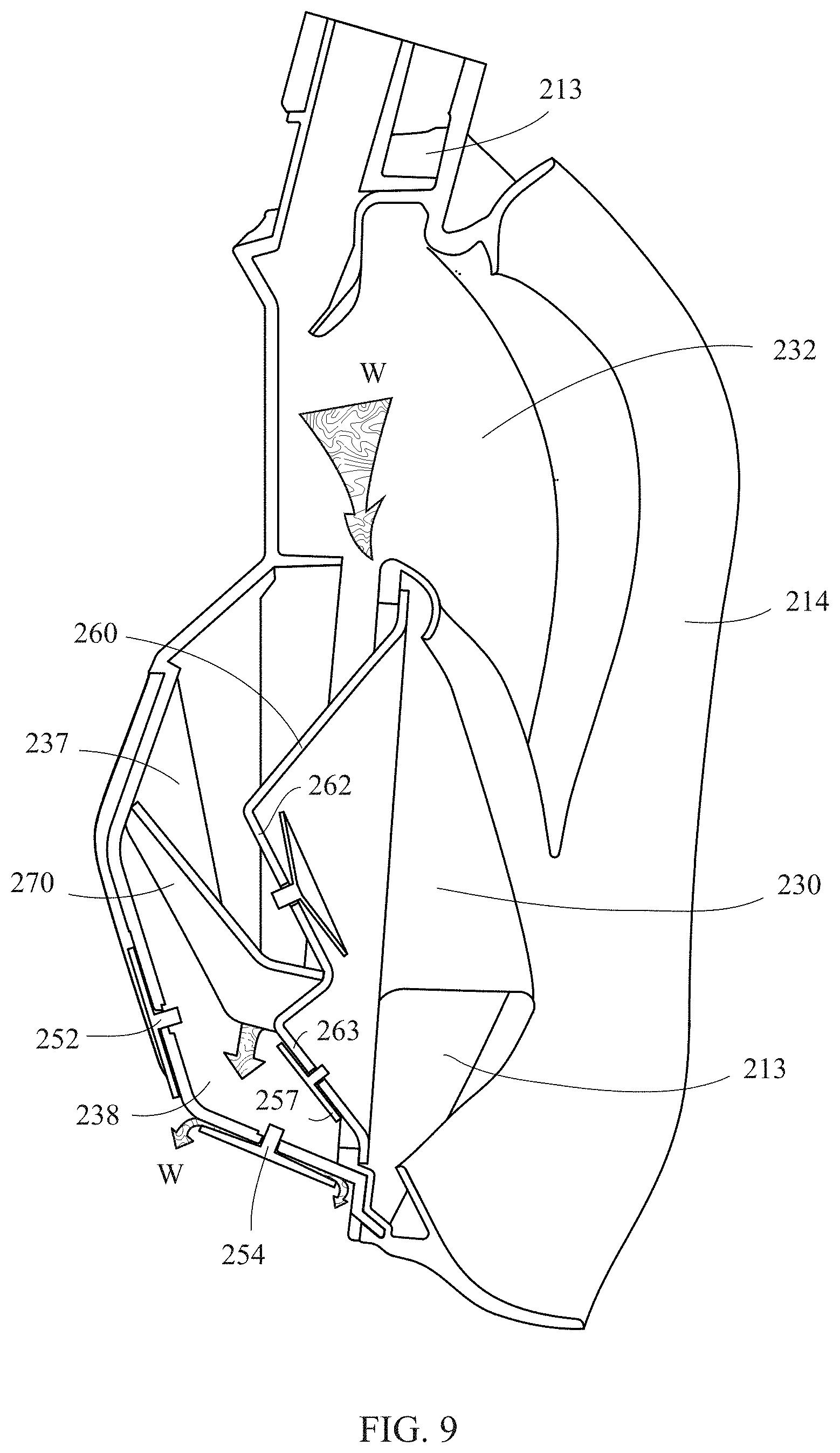
[0051] With reference to FIG. 6, FIG. 8 and FIG. 9, the preferred air path of the full-face mask 200 of this application is described as follows:
[0052] When the user inhales, the air B can flow from the breathing tube to the guide space 237 from the upper space 232 and through the interval 215 and enter the proximal space 235 through the intake valve 241 on the upper plane 262 of the first partition 260, and is directly inhaled by the user, so the amount of clean air (oxygen) inhaled by the user can easily reach and exceed the safety standard. When the user exhales, the pressure in the proximal space 235 increases, so that the intake valve 241 becomes closed. At this time, part of the dirty air C flows from the proximal space to the channel 213 and then to the breathing tube 220 to be discharged, and part of the dirty air C flows through the inner exhaust valve 257 from the proximal space into the temporary storage space 238, and then flows out through the upper exhaust valve 252 and/or the lower drain valve 254. As shown in FIG. 9, if water W accidentally flows into the full-face mask 200 and accumulates in the temporary storage space 238, when the user exhales, the pressure of the temporary storage space 238 will be more easily increased due to the blocking of the second partition 270, and the water W will be discharged from the lower drain valve 254 more easily, and will hardly accumulate to the height of the upper exhaust valve 252. In this way, the upper exhaust valve 252 may be specially responsible for processing the dirty air exhaled by the user, thereby improving the efficiency of discharging the dirty air and improving the safety of use.
[0053] As shown in FIG. 10, the lens portion 216 of the full-face mask 200 of this embodiment may further comprise a guide opening 211 located below a guide sheet 217 extending from the inner side of the lens portion 216, e.g., between the guide space 237 and the temporary storage space 238. When water W penetrates into the upper space 232 of the full-face mask 200, it flows along the inner side of the lens portion 216 or the guide sheet 217 to the guide opening 211 and to the lower drain valve 254 of the temporary storage space 238, and then the water is discharged to the outside as the user moves or exhales. Even if the water W is not discharged immediately, the second partition 270 may be arranged to prevent the water W from flowing back to the guide space 237 along the guide opening 211 or reaching the position of the intake valve 241 and being accidentally inhaled by the user. Alternatively, the soft portion 214 may comprise a stopper (not shown), which can cover the guide opening 211 after the soft portion 214 is connected with the lens portion 216 to prevent the water W from flowing back to the guide space 231 along the guide opening 211. That is, the stopper may serve as a one-way valve so that the water W flows to the temporary storage space 238 in a unidirectional manner.
[0054] As shown in FIG. 11, after the soft portion 214 is connected with the lens portion 216, a channel 213 may be formed inside a periphery of the full-face mask 200. The channel 213 has a splitter 213a, the splitter 213a may be a part of the lens portion 216 or a part of the soft portion 214, and is arranged at the connection between the channel 213 and the breathing tube 220 to block the direct circulation of dirty air from a lower end of the channel 213 to the breathing tube 220. Further speaking, when the dirty air C exhaled by the user enters a lower end of the channel 213 from the lower space 234 and then flows to an upper end of the channel 213 and to the breathing tube 220, the splitter 213a can prevent the circulation of the dirty air in the vicinity of the breathing tube 220 (the air in the left channel flows directly from the right channel, or vice versa); otherwise, the dirty air C (carbon dioxide) cannot be completely and smoothly discharged and accumulated in the full-face mask 200. In this way, the danger caused by insufficient clean air inhaled by the user can be avoided. Due to the arrangement of the splitter 213a, the dirty air C from the left and right channels will be blocked and respectively flow to the breathing tube 220 more smoothly and directly, and then discharged to the outside of the full-face mask 200.
[0055] As shown in FIG. 12, the mask body 210 may further comprise a frame 219 and an outer cover 218, wherein the frame 219 may be clamped around the lens portion 216 and the soft portion 214 to further protect the lens portion 216. The outer cover 218 may be detachably fixed to the lens portion 216 or the frame 219 or integrally formed with the frame 219, thereby preferably shielding the region of the lens portion 216 having the upper exhaust valve 252 and the lower drain valve 254 to protect the upper exhaust valve 252 and the lower drain valve 254. If the upper exhaust valve 252 and the lower drain valve 254 have structures that are not easily damaged, then the outer cover 218 may not be required.
[0056] According to the above descriptions, because the upper space 232 and the lower space 234 of the full-face mask of the present invention are directly connected and the intake valve 241 is close to the nose of the user, the user can more efficiently breathe clean air through this shorter and more direct air inhalation path. On the contrary, when the user exhales with the nose and/or the mouth, the intake valve 241 will be directly pressurized to cover the air inlet 231 and turn into a closed state if the intake valve 241 is a constantly open intake valve, and the dirty air C may flow directly to the breathing tube 220 through the channel 213 to be discharged. Alternatively, when the first partition 260 is further provided with an inner exhaust valve 257, the dirty air C can be more efficiently discharged to the temporary storage space 238 because the position of the inner exhaust valve 257 is close to the user's mouth. Meanwhile, the water W accumulated in the temporary storage space 238 can be discharged out of the mask body 210 so that the dirty air C and accumulated water are not easy to flow back or accumulate, thereby meeting various safety standards. By providing the first partition to isolate the water inadvertently flowing into the full-face mask from the nose and mouth of the user, the present invention can avoid anxiety and panic of the user caused by touching the water. Moreover, the present invention may be further provided with the second partition and/or the stopper to block the backflow of the water accumulated in the mask, thereby further increasing the safety in use. Such a design can greatly improve the problems of the prior art that it is difficult to inhale enough clean air (includes the content of carbon dioxide is too high because carbon dioxide cannot be exhaled completely) and the user feels anxious because of touching the accumulated water, and various safety standards are met no matter during air inhalation or exhalation.
[0057] The above disclosure is related to the detailed technical contents and inventive features thereof. People skilled in this field may proceed with a variety of modifications and replacements based on the disclosures and suggestions of the invention as described without departing from the characteristics thereof. Nevertheless, although such modifications and replacements are not fully disclosed in the above descriptions, they have substantially been covered in the following claims as appended.
* * * * *
References
D00000
D00001
D00002
D00003
D00004
D00005
D00006
D00007
D00008
D00009
D00010
D00011
D00012

D00013

D00014

XML
uspto.report is an independent third-party trademark research tool that is not affiliated, endorsed, or sponsored by the United States Patent and Trademark Office (USPTO) or any other governmental organization. The information provided by uspto.report is based on publicly available data at the time of writing and is intended for informational purposes only.
While we strive to provide accurate and up-to-date information, we do not guarantee the accuracy, completeness, reliability, or suitability of the information displayed on this site. The use of this site is at your own risk. Any reliance you place on such information is therefore strictly at your own risk.
All official trademark data, including owner information, should be verified by visiting the official USPTO website at www.uspto.gov. This site is not intended to replace professional legal advice and should not be used as a substitute for consulting with a legal professional who is knowledgeable about trademark law.