Trolley And Mechanical Braking System Therefor
BRUNNER; Yaron ; et al.
U.S. patent application number 15/733249 was filed with the patent office on 2021-04-01 for trolley and mechanical braking system therefor. This patent application is currently assigned to KETER PLASTIC LTD.. The applicant listed for this patent is KETER PLASTIC LTD., MILWAUKEE ELECTRIC TOOL CORPORATION. Invention is credited to Yaron BRUNNER, Omer MENASHRI, Uri PARIZER, Izhar SHANY, Grant T. SQUIERS.
| Application Number | 20210094600 15/733249 |
| Document ID | / |
| Family ID | 1000005306870 |
| Filed Date | 2021-04-01 |


| United States Patent Application | 20210094600 |
| Kind Code | A1 |
| BRUNNER; Yaron ; et al. | April 1, 2021 |
TROLLEY AND MECHANICAL BRAKING SYSTEM THEREFOR
Abstract
Provided are mechanical braking systems for wheeled trolleys, trolleys including a mechanical braking system and methods for controlling movement thereof.
| Inventors: | BRUNNER; Yaron; (Kibbutz Gvat, IL) ; MENASHRI; Omer; (Kibbutz Afikim, IL) ; SHANY; Izhar; (Kibutz Gvat, IL) ; PARIZER; Uri; (Kibbutz Hukok, IL) ; SQUIERS; Grant T.; (Cudahy, WI) | ||||||||||
| Applicant: |
|
||||||||||
|---|---|---|---|---|---|---|---|---|---|---|---|
| Assignee: | KETER PLASTIC LTD. Herzelyia WI MILWAUKEE ELECTRIC TOOL CORPORATION Brookfield |
||||||||||
| Family ID: | 1000005306870 | ||||||||||
| Appl. No.: | 15/733249 | ||||||||||
| Filed: | December 20, 2018 | ||||||||||
| PCT Filed: | December 20, 2018 | ||||||||||
| PCT NO: | PCT/IL2018/051381 | ||||||||||
| 371 Date: | June 17, 2020 |
Related U.S. Patent Documents
| Application Number | Filing Date | Patent Number | ||
|---|---|---|---|---|
| PCT/US2018/044629 | Jul 31, 2018 | |||
| 15733249 | ||||
| 62608302 | Dec 20, 2017 | |||
| 62609985 | Dec 22, 2017 | |||
| 62686301 | Jun 18, 2018 | |||
| Current U.S. Class: | 1/1 |
| Current CPC Class: | F16D 2125/64 20130101; F16D 63/00 20130101; B62B 3/04 20130101; B62B 3/008 20130101; B62B 5/049 20130101; B62B 5/0433 20130101 |
| International Class: | B62B 5/04 20060101 B62B005/04; B62B 3/04 20060101 B62B003/04; F16D 63/00 20060101 F16D063/00 |
Claims
1. A wheeled trolley comprising: a platform base member; a wheel set defining a ground contact surface; and a foot lever articulated to the platform base member through a biasing mechanism, said foot lever being configured to have a first position in which it is not in contact with the ground contact surface, and a second position in which the lever is in contact with the ground contact surface, against a biasing effect of the biasing mechanism, and wherein the foot lever is biased into said first position by the biasing mechanism.
2. The trolley of claim 1, wherein the biasing mechanism comprises a pivoting structure and a biasing member.
3. The trolley of claim 2, wherein the pivoting structure is arranged to pivot about an axis of rotation, and wherein the foot lever and the biasing member are arranged on the pivoting structure on opposite sides across the axis of rotation from one another.
4. The trolley of claim 2, wherein the pivoting structure is pivotably articulated to the platform about an axis of rotation and wherein the biasing member is disposed at one side of the axis of rotation and below the platform, and the foot lever is disposed at an opposite side of the axis of rotation adjacent an edge of the platform.
5. The trolley of claim 2, wherein the biasing member biases the foot lever into the first position, and wherein, in use, a force applied to the foot lever against the biasing effect of the biasing member urges the foot lever into the second position.
6. The trolley of claim 5, wherein, in use, upon removal of the applied force, the biasing member biases the foot lever to return to the first position.
7. The trolley of claim 1, wherein the biasing member is an elastically deformable member disposed between a bottom face of the platform and a support member articulated to the pivoting structure.
8. The trolley of claim 7, wherein the biasing member is a compression spring.
9. The trolley of claim 7, wherein the pivoting structure has a first arm extending substantially parallel to the axis of rotation, and two parallelly extending second arms extending from the first arm, where the support member is articulated to said first arm and wherein the foot lever extends between respective end portions of the second arms.
10. The trolley of claim 9, wherein in the first position, an end portion of each of the second arms bears against a bottom face of the platform adjacent an edge of the platform.
11. (canceled)
12. The trolley of claim 7, wherein the foot lever is pivotably articulated at the ends of the second arms about an axis parallel to the axis of rotation.
13. The trolley of claim 7, wherein the pivoting structure is articulated to the platform by a pair of articulation members, each fixed to a respective second arm, said articulation members being configured with an articulation axel, the articulation axels co-extends with the axis of rotation.
14. The trolley of claim 13, wherein (i) each of the articulation axels is integral with the articulation member, or (ii) each of the articulation axels is removably received within the articulation member.
15. (canceled)
16. The trolley of claim 7, wherein the biasing member is a tension spring articulated to the second arms, and disposed between the axis of rotation and the platform edge.
17. The trolley of claim 1, wherein the foot lever is pivotably articulated to the pivoting structure.
18. The trolley of claim 17, wherein the foot lever, when in its first position, has an operable position disposed closest to the ground contact surface, and a collapsed position, in which the foot lever is stowed in proximity to the platform.
19. (canceled)
20. The trolley of claim 1, wherein (i) the foot lever has a foot-engaging surface at a top face thereof and a ground-engaging surface and a bottom face thereof, and wherein the ground-engaging surface comprises one or more ground contact elements, (ii) a foot-engaging surface of the foot lever extends below a bottom face of an edge of the platform, at a distance facilitating inserting at least a front portion of a user's foot, and/or (iii) the foot lever is pivotally articulable between a position in which an end of the foot lever is at a first distance away from the ground contact surface and a position in which the end of the foot lever is at a second distance away from the ground contact surface, wherein the second distance is greater than the first distance.
21. (canceled)
22. (canceled)
23. The trolley of claim 1, wherein the pivoting structure is integrally configured with the foot lever.
24. (canceled)
25. The trolley of claim 1, wherein a top surface of the platform is configured with utility module articulation arrangement, for detachably-attaching thereto of at least one utility module.
26. (canceled)
27. (canceled)
28. A mechanical braking system for a wheeled trolley having a platform base member and a wheel set defining a ground contact surface, the mechanical braking system comprising: a foot lever articulable to the platform base member through a biasing mechanism, said foot lever being configured to have a first position in which it is not in contact with the ground contact surface, and a second position in which the lever is in contact with the ground contact surface, against a biasing effect of the biasing mechanism, and wherein the foot lever is biased into said first position by the biasing mechanism.
Description
TECHNOLOGICAL FIELD
[0001] The present disclosure relates to mechanical braking systems for wheeled trolleys, trolleys comprising a mechanical braking system and methods for controlling movement thereof.
BACKGROUND
[0002] Trolleys, wheeled platforms and the like are conventionally used for easy transport of bulky and heavy objects. It is desirable to provide improved means of control of movement the trolley, in particular when maneuvering objects onto and off of the trolley.
General Description
[0003] According to a first aspect of this disclosure, there is provided a wheeled trolley comprising: a platform base member; a wheel set defining a ground contact surface; and a foot lever articulated to the platform base member through a biasing mechanism. The foot lever is configured to have a first position in which it is not in contact with the ground contact surface, and a second position in which the lever is in contact with the ground contact surface, against a biasing effect of the biasing mechanism, and the foot lever is biased into said first position by the biasing mechanism.
[0004] According to another aspect, there is provided a mechanical braking system for a wheeled trolley as defined above.
[0005] Further provided is a method for controlling movement of a trolley as disclosed herein, comprising applying force to the foot lever to urge the lever against the biasing effect from the first position into the second position.
[0006] Any one or more of the following features, designs and configurations can be incorporated in any of the aspects of this disclosure, solely or in any combination thereof: [0007] The biasing mechanism can comprise a pivoting structure and a biasing member. [0008] The pivoting structure cam be arranged to pivot about an axis of rotation, and wherein the foot lever and the biasing member are arranged on the pivoting structure on opposite sides across the axis of rotation from one another. [0009] The pivoting structure can be pivotably articulated to the platform about an axis of rotation and wherein the biasing member is disposed at one side of the axis of rotation and below the platform, and the foot lever is disposed at an opposite side of the axis of rotation adjacent an edge of the platform. [0010] The biasing member can bias the foot lever into the first position, and wherein, in use, a force applied to the foot lever against the biasing effect of the biasing member urges the foot lever into the second position. Further, when in use, upon removal of the applied force, the biasing member can bias the foot lever to return to the first position. [0011] The biasing member can be an elastically deformable member disposed between a bottom face of the platform and a support member articulated to the pivoting structure, e.g. the biasing member can be a compression spring. [0012] The pivoting structure can have a first arm extending substantially parallel to the axis of rotation, and two parallelly extending second arms extending from the first arm, where the support member is articulated to said first arm and wherein the foot lever extends between respective end portions of the second arms. [0013] In the first position, an end portion of each of the second arms bears against a bottom face of the platform adjacent an edge of the platform, optionally wherein bearing of an end portion of at least one of the second arms is against the bottom face of the platform is cushioned. [0014] The foot lever can be pivotably articulated at the ends of the second arms about an axis parallel to the axis of rotation. [0015] The pivoting structure can be articulated to the platform by a pair of articulation members, each fixed to a respective second arm, said articulation members being configured with an articulation axel, the articulation axels co-extends with the axis of rotation. Particularly, each of the articulation axels is integral with the articulation member, or each of the articulation axels is removably received within the articulation member. [0016] The biasing member can be a tension spring articulated to the second arms, and disposed between the axis of rotation and the platform edge. [0017] The foot lever can be pivotably articulated to the pivoting structure. [0018] The foot lever, when in its first position, can have an operable position disposed closest to the ground contact surface, and a collapsed position, in which the foot lever is stowed in proximity to the platform. [0019] The trolley can further comprise an arresting mechanism for arresting the foot lever at the stowed position. [0020] The foot lever can have a foot-engaging surface at a top face thereof and a ground-engaging surface and a bottom face thereof, and wherein the ground-engaging surface comprises one or more ground contact elements. [0021] The foot lever can have a foot-engaging surface, that extends below a bottom face of an edge of the platform, at a distance facilitating inserting at least a front portion of a user's foot. [0022] The foot lever can be pivotally articulable between a position in which an end of the foot lever is at a first distance away from the ground contact surface and a position in which the end of the foot lever is at a second distance away from the ground contact surface, wherein the second distance is greater than the first distance. [0023] The pivoting structure can be integrally configured with the foot lever. [0024] The mechanical braking system can be detachably attachable at a bottom face of the trolley. [0025] The trolley can have a top surface of the platform that is configured with utility module articulation arrangement, for detachably-attaching thereto of at least one utility module.
BRIEF DESCRIPTION OF THE DRAWINGS
[0026] In order to better understand the subject matter that is disclosed herein and to exemplify how it may be carried out in practice, embodiments will now be described, by way of non-limiting example only, with reference to the accompanying drawings, in which:
[0027] FIGS. 1A-1C show, respectively:
[0028] a top perspective view of a trolley and a mechanical braking system according to one embodiment of this disclosure (FIG. 1A),
[0029] a top perspective view of the mechanical braking mechanism of FIG. 1A without the trolley (FIG. 1B),
[0030] and a bottom perspective view of the trolley and mechanical braking system (FIG. 1C).
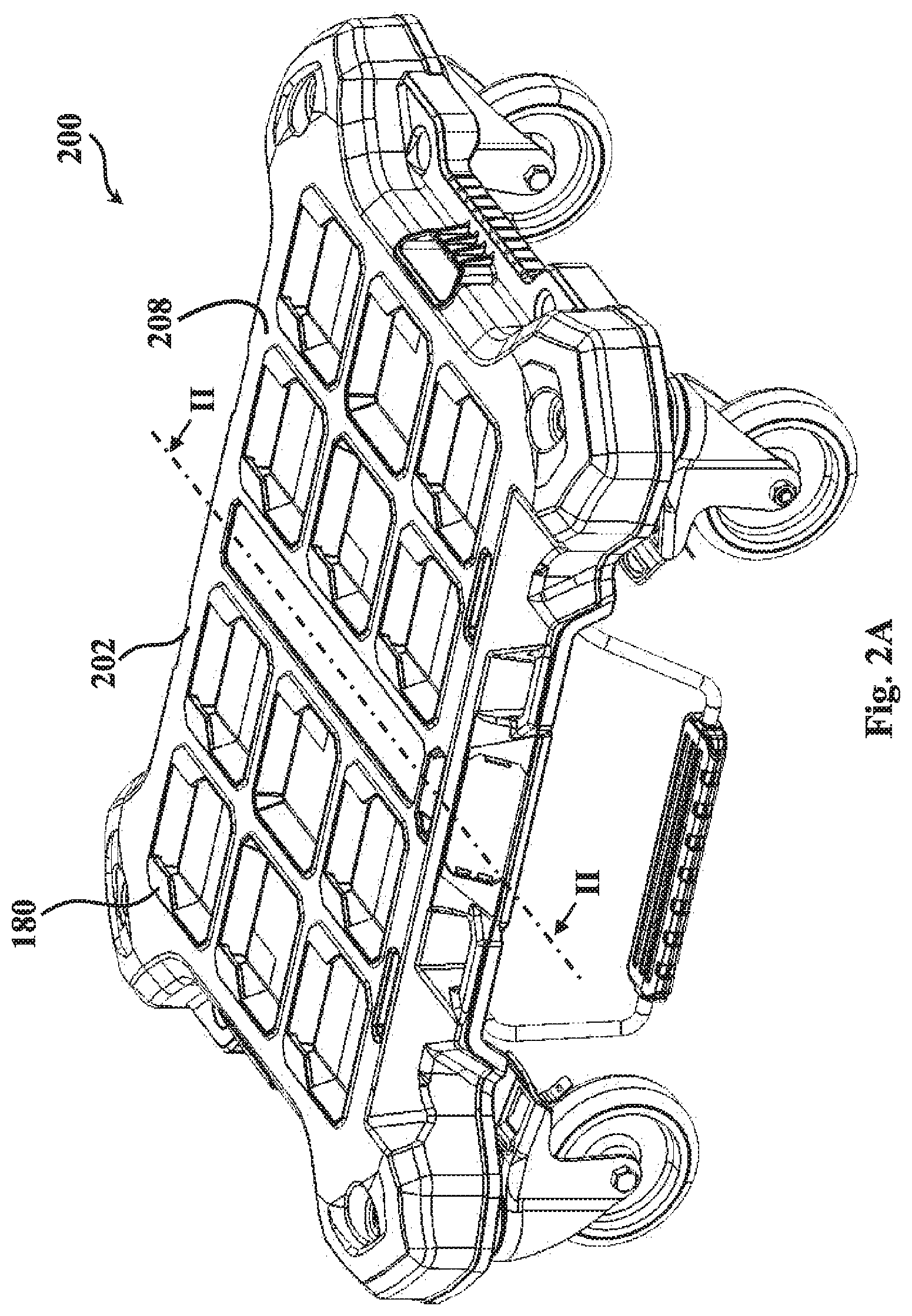
[0031] FIGS. 2A-2C show, respectively:
[0032] a top perspective view of a trolley and a mechanical braking system according to another embodiment of this disclosure (FIG. 2A),
[0033] a planar side-view cross-section along line II-II of FIG. 2A (FIG. 2B), and a perspective top view of the particular example of the mechanical braking system (FIG. 2C).
[0034] FIG. 3A is a schematic side-view illustrating foot-operation of the mechanical braking system.
[0035] FIG. 3B is a perspective view illustrating respective first and second positions of the mechanical braking system.
DETAILED DESCRIPTION OF EMBODIMENTS
[0036] An embodiment of a trolley, also known as a dolly cart or hand truck, generally designated 100 is shown in FIGS. 1A-1C. Trolley 100 comprises a platform base member 102 attached to a wheel set comprising four castor wheels 104. The wheel set defines a ground contact surface 106 (shown in FIG. 1A), which is a surface contacted by the wheel set. Platform base member 102 comprises a top face 108 and a bottom surface 110. In this context, "top surface" and "bottom surface" refer to surfaces respectively further from and closer to the ground contact surface. Similarly, "up" and "down" refer to direction away from and towards the ground contact surface respectively.
[0037] The top face 108 of the platform base member 102 is generally used for placing of heavy or bulky items, for transport thereof (as shown schematically in FIG. 3A).
[0038] The trolley 100 further comprises a mechanical braking system 120 disposed at the bottom surface 110 of the platform base member 102. With reference to FIG. 1B, there is shown the mechanical braking system 120 without the platform base member 102 or castor wheels 104. The mechanical braking system 120 comprises a foot lever 122 attached to a biasing mechanism 124. Biasing mechanism 124 comprises a pivoting structure 126, and a biasing member 128 in the form of, in this example, a compression spring. In the exemplified embodiment, the biasing member 128 is disposed between spring receptacle 130 at the bottom surface 110 of the platform base member 102 (FIG. 1C) and a support member 132 articulated to the pivoting structure 126. The pivoting structure 120 comprises two second arms 134 and 136, parallelly extending one to the other, and extending from first arm 138 at a substantially right-angle. The support member 132 is articulated to the first arm 138.
[0039] The pivoting structure 120 is articulated to the platform 102 by a pair of articulation members 140, each fixed to a respective second arm 134,136, the articulation members being configured with an articulation axel 142. In the present example, each of axels 142 is split into left and right coextending portions 142' and 142''. The axels 142 define between them an axis of rotation 144. Each of the axels 142 is configured, for snap engagement, however pivotably, within axel receptacle 143 configured at the bottom surface of the platform 102.
[0040] The first arm 138 extends substantially parallel to the axis of rotation 144, and two parallelly extending second arms 134,136 extend from the first arm; such that the support member 132 is articulated to the first arm.
[0041] The compression spring 128 is received, at a first end thereof, within receptacle 158 of the support member 132 and an opposite, top end within receptacle 160 at the bottom face of the platform 102, so as to pivotally bias the braking mechanism 120 into a first position, in which the foot lever is not in contact with the ground contact surface.
[0042] In other embodiments (not shown), a contraction biasing member can be disposed intermediate the axis of rotation 144 and the end portions of the second arms 134,136. It is noted that instead of a compression spring, other biasing members are also encompassed by the present disclosure, e.g. a piston mechanism, resilient member, etc.
[0043] The foot lever 122 extends between respective end portions of the second arms 134,136, and in this particular example is pivotably secured about a pivot axis 146, which is parallel to the axis of rotation 144.
[0044] The foot lever 122 comprises two parallel arms 148 and a foot-engaging member 150, which has a foot-engaging surface 152 and a ground-engaging surface 154. The ground engaging surface 154 can be fitted with at least one ground contact element 156 (as seen in FIG. 1C).
[0045] The top face 108 of platform 102 is configured with utility module articulation arrangement, generally designated 180, for detachably-attaching thereto of at least one utility module, as described for example, in Applicants' PCT patent publication WO2017/191628, incorporated herein by reference for its relevant parts.
[0046] At its normal state, the braking mechanism is disposed in the first position, so that the foot lever is remote from the ground contact surface and does not hinder the rolling or moving of the trolley along the surface. When it is required to load/unload/articulate/detach a utility module 400 from the top face 108 of the trolley 300 (as seen, for example in FIG. 3A), it is advantageous to temporarily prevent the trolley from displacing over the ground surface 106, whereupon applying a force F by a user's foot R to the foot lever 122 against the biasing effect of the biasing member 128 urges the foot lever into a second position, in which it is in contact with the ground contact surface. This can also be seen in FIG. 3B, in which the lever is shown in a dashed line in the first position, and in solid line in the ground-engaging second position.
[0047] Another example of a trolley 200 and its associated mechanical braking mechanism 220 is shown in FIGS. 2A-2C. It is noted that in FIGS. 2A-3C, elements having same functionality as those of FIGS. 1A-1C will be given similar reference numbers, shifted by 100.
[0048] In the exemplary trolley of FIGS. 2A-2C, pivoting structure 220 is a continuous frame-like member that is constituted by the first arm 238 and its two integrally-formed second arms 234,236, and continuously extending to lever arms 248, and further to a horizontal portion 249 onto which the lever 222 is articulated.
[0049] In this specific example, articulation members 240 are each configured with an axel bushing 241, each receiving an axel 242 in a removable manner. The axel 242 is configured for pivotal articulation within axel receptacle (not seen) at the bottom face of the platform.
[0050] Shown in FIG. 2B is a side-view cross section of trolley 200. As can be seen, the foot-engaging surface 252 of the foot lever 222 extends below a bottom face of an edge of the platform 253, at a distance D facilitating inserting at least a front portion of a user's foot (as exemplified in FIG. 3A). Although this is shown specifically for the embodiment of FIGS. 2A-2C, it is to be understood that the same principle of operation also applies to the example shown in FIGS. 1A-1C.
[0051] Those skilled in the art to which this invention pertains will readily appreciate that numerous changes, variations, and modifications can be made without departing from the scope of the presently disclosed subject matter, mutatis mutandis.
* * * * *
D00000
D00001
D00002
D00003
D00004
D00005
D00006
D00007
XML
uspto.report is an independent third-party trademark research tool that is not affiliated, endorsed, or sponsored by the United States Patent and Trademark Office (USPTO) or any other governmental organization. The information provided by uspto.report is based on publicly available data at the time of writing and is intended for informational purposes only.
While we strive to provide accurate and up-to-date information, we do not guarantee the accuracy, completeness, reliability, or suitability of the information displayed on this site. The use of this site is at your own risk. Any reliance you place on such information is therefore strictly at your own risk.
All official trademark data, including owner information, should be verified by visiting the official USPTO website at www.uspto.gov. This site is not intended to replace professional legal advice and should not be used as a substitute for consulting with a legal professional who is knowledgeable about trademark law.