Honing Machine
Moos; Uwe ; et al.
U.S. patent application number 17/033754 was filed with the patent office on 2021-04-01 for honing machine. This patent application is currently assigned to KADIA Produktion GmbH + Co.. The applicant listed for this patent is KADIA Produktion GmbH + Co.. Invention is credited to Uwe Moos, Roland Regler.
| Application Number | 20210094142 17/033754 |
| Document ID | / |
| Family ID | 1000005149755 |
| Filed Date | 2021-04-01 |


| United States Patent Application | 20210094142 |
| Kind Code | A1 |
| Moos; Uwe ; et al. | April 1, 2021 |
HONING MACHINE
Abstract
A honing machine for honing a bore in a workpiece comprises a support structure fixed to the machine and at least one honing unit which is mounted on the support structure and which has a spindle unit (150) in which a spindle shaft (152) is rotatably mounted, wherein the spindle shaft (152) is rotatable about a spindle axis (155) by means of a rotary drive (450) and, at a tool-side end (153), has a device for the fastening of an expandable honing tool. The honing machine furthermore comprises a stroke drive for generating a stroke movement of the spindle unit (150) and an expansion drive (550) for expanding the honing tool, wherein the expansion drive is coupled to an advancing rod (460) which runs in the interior of the spindle shaft. The spindle unit (150) has a spindle unit housing (310) which has a first housing portion (310-1) for accommodating the rotary drive (450) and a second housing portion (310-2) for accommodating the expansion drive (550). The rotary drive (450) is accommodated in an exchangeable first cartridge (400) and the expansion drive (550) is accommodated in a second cartridge (500) which is exchangeable independently of the first cartridge (400), wherein the first cartridge (400) is introducible into the first housing portion (310-1) and the second cartridge (500) is introducible into the second housing portion (310-2).
| Inventors: | Moos; Uwe; (Dettingen an der Erms, DE) ; Regler; Roland; (Georgensgmund, DE) | ||||||||||
| Applicant: |
|
||||||||||
|---|---|---|---|---|---|---|---|---|---|---|---|
| Assignee: | KADIA Produktion GmbH + Co. Nurtingen DE |
||||||||||
| Family ID: | 1000005149755 | ||||||||||
| Appl. No.: | 17/033754 | ||||||||||
| Filed: | September 26, 2020 |
| Current U.S. Class: | 1/1 |
| Current CPC Class: | B24B 33/027 20130101 |
| International Class: | B24B 33/02 20060101 B24B033/02 |
Foreign Application Data
| Date | Code | Application Number |
|---|---|---|
| Sep 27, 2019 | DE | 102019214873.5 |
Claims
1. A honing machine for honing a bore in a workpiece, comprising: a support structure fixed to the machine; at least one honing unit mounted on the support structure and which has a spindle unit in which a spindle shaft is rotatably mounted, wherein the spindle shaft is rotatable about a spindle axis by means of a rotary drive and, at a tool-side end, has a device for the fastening of an expandable honing tool, a stroke drive for generating a stroke movement of the spindle unit; an expansion drive for expanding the honing tool, wherein the expansion drive is coupled to an advancing rod which runs in the interior of the spindle shaft; the spindle unit comprising a spindle unit housing comprises a first housing portion for accommodating the rotary drive and a second housing portion for accommodating the expansion drive, wherein the rotary drive is accommodated in an exchangeable first cartridge and the expansion drive is accommodated in a second cartridge which is exchangeable independently of the first cartridge, wherein the first cartridge is introducible into the first housing portion and the second cartridge is introducible into the second housing portion.
2. The honing machine according to claim 1, wherein the spindle unit housing is formed as a monocoque housing in which the first housing portion is formed as a single piece with the second housing portion.
3. The honing machine according to claim 1, wherein the first cartridge and the second cartridge are introducible into the spindle unit housing from opposite sides thereof.
4. The honing machine according to claim 1, wherein, on an inner side of the first housing portion, there is formed at least one first fitting surface which, in contact with at least one corresponding first fitting surface on the first cartridge, effects an alignment of the first cartridge in the first housing portion, and/or wherein, on an inner side of the second housing portion, there is formed at least one second fitting surface which, in contact with at least one corresponding second fitting surface on the second cartridge, effects an alignment of the second cartridge in the second housing portion.
5. The honing machine according to claim 1, wherein, on the spindle unit housing, there are formed axial stop surfaces for predefining an axial position of the first cartridge in the first housing portion and of the second cartridge in the second housing portion.
6. The honing machine according to claim 1, wherein, on a side, which is to face towards the second cartridge, of the first cartridge, and on a side, which is to face towards the first cartridge, of a housing portion of the spindle unit housing, there are arranged corresponding connecting elements of at least one plug-type connection for the transfer of at least one of fluid, electrical power and electrical signals.
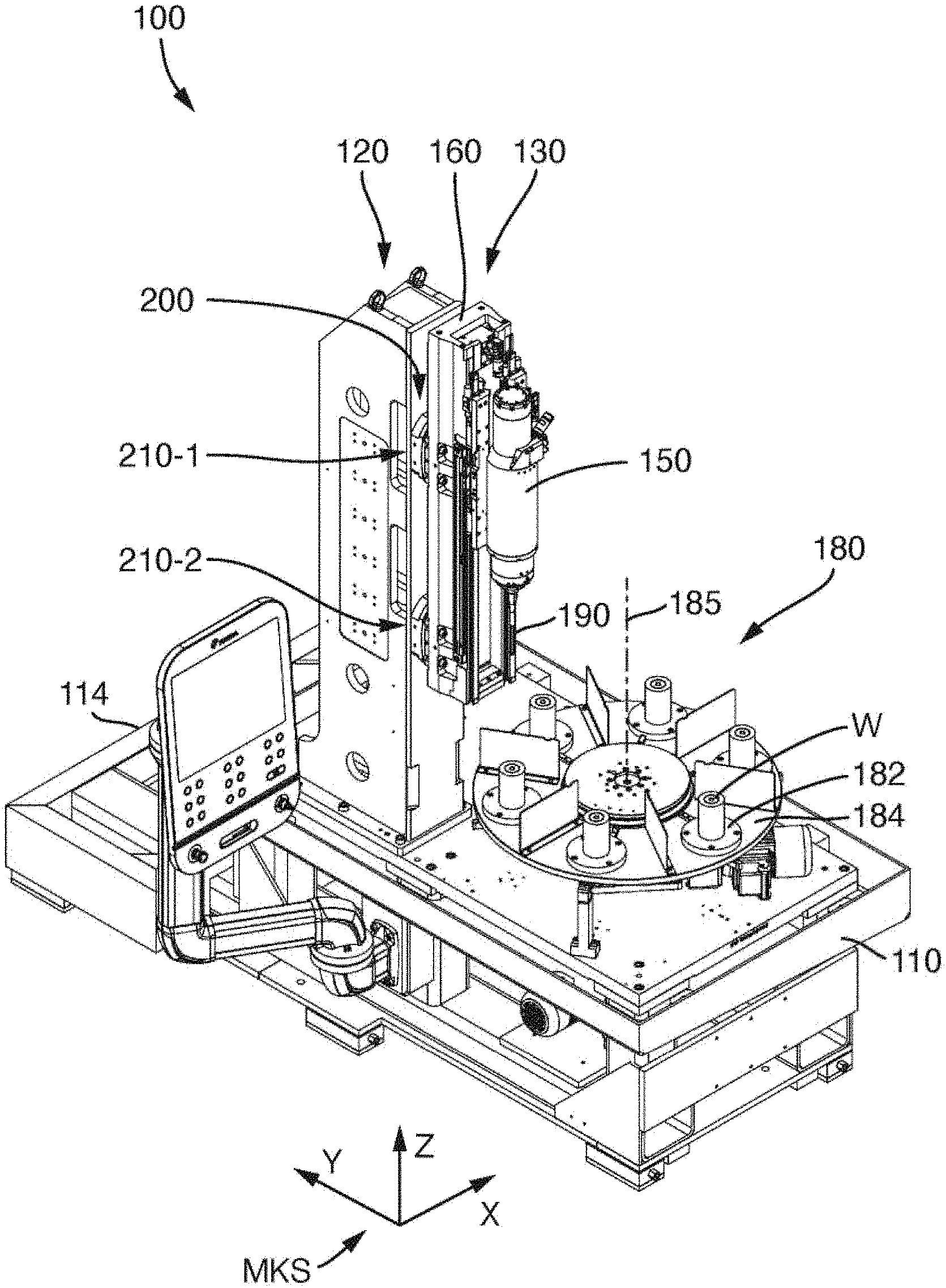
7. The honing machine according to claim 1, wherein the expansion drive comprises has a torque motor.
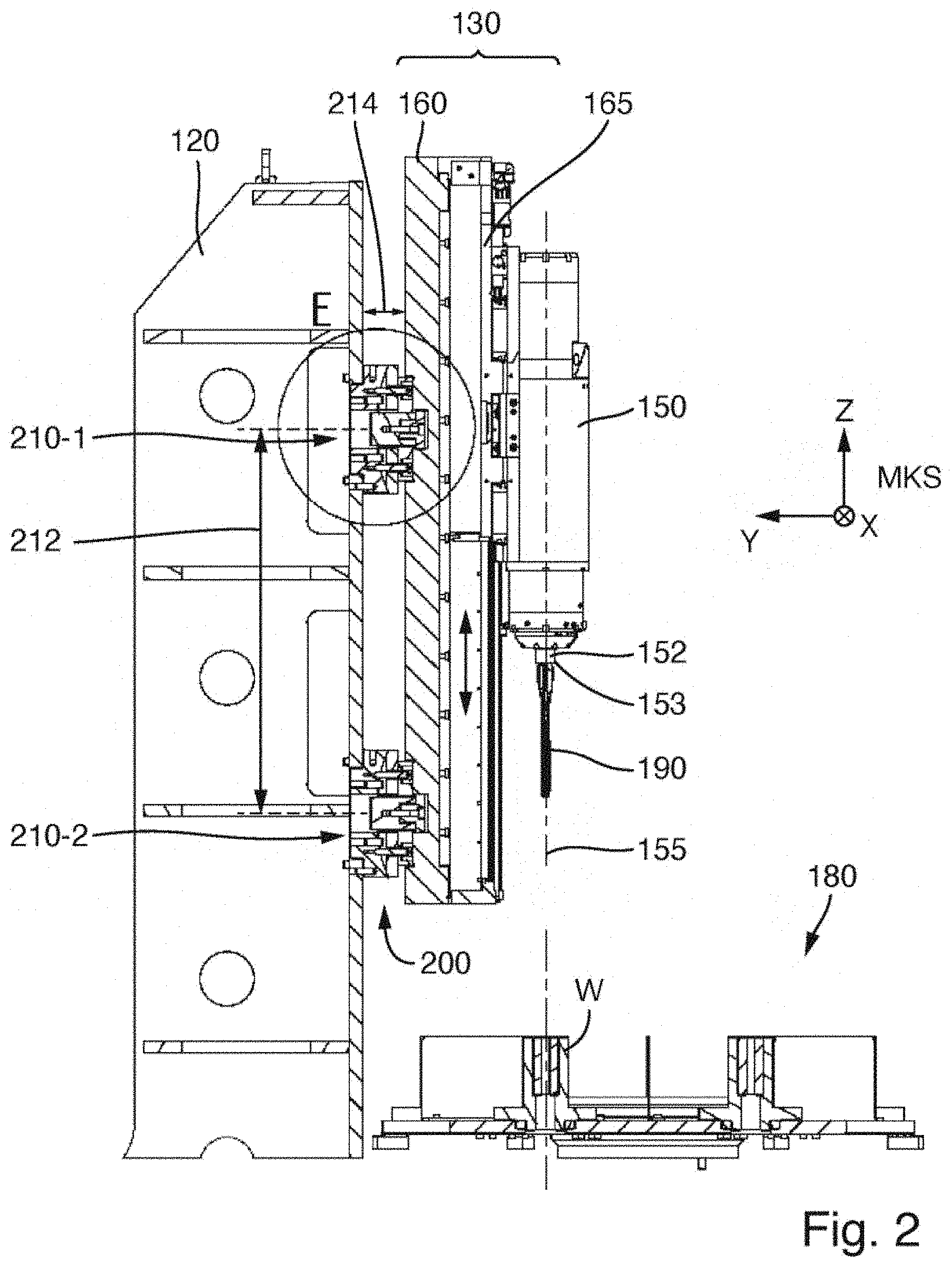
8. The honing machine according to claim 1, wherein, in a cartridge housing of the first cartridge, there are formed fluid channels for conducting fluid.
9. The honing machine according to claim 8, wherein the fluid is cooling fluid for the rotary drive.
Description
FIELD OF APPLICATION AND PRIOR ART
[0001] This application claims priority to German Patent Application DE 10 2019 214 873.5 filed Sep. 27, 2019, the entirety of which is incorporated herein by reference.
[0002] The invention relates to a honing machine for honing a bore in a workpiece.
[0003] Honing is a cutting machining method using geometrically undefined cutting edges, in the case of which a honing tool performs a cutting movement composed of two components and there is constant areal contact between one or more cutting material bodies, for example honing strips, of the honing tool and the bore inner surface to be machined. The kinematics of a honing tool are characterized by a superposition of a rotational movement and a stroke movement running in an axial direction of the bore. Normally, an optional expansion movement is also provided, which leads to a variation of the effective diameter of the honing tool.
[0004] A one-off stroke movement of the honing tool within the bore, composed of an advancement into the bore and a subsequent retraction out of the bore, is referred to as "bobbing". A repeated stroke movement within the bore, that is to say an advancement into the bore, followed by a cyclic reciprocating movement within the bore, and a subsequent retraction out of the bore at the end, is referred to as "oscillating". In the case of oscillating honing processes, an expansion movement is generally required, because the effective diameter of the honing tool is actively varied during the oscillation. Additionally, the wear of the cutting material body is generally compensated by means of the expansion movement.
[0005] The kinematics of the honing tool generate a surface structure with criss-crossing machining marks on the bore inner surface. Surfaces finish-machined by honing can satisfy extremely high demands with regard to dimensional and shape tolerances, and in some cases have a special surface roughness and structure, such as for example a plateau surface, which combines low wear owing to a high material percentage contact area with the capability of being able to readily receive an oil film for lubrication. Therefore, many highly loaded sliding surfaces in engines or engine components, for example cylinder barrels in engine blocks or bore inner surfaces in housings of injection pumps, are machined by honing.
[0006] A honing machine is a machine tool suitable for the honing of bores in workplaces. Said honing machine has at least one honing unit which is mounted on a support structure fixed to the machine, for example a stand, a column or a frame. A honing unit comprises a spindle unit in which a spindle shaft is rotatably mounted. The spindle shaft is rotatable about its spindle axis by means of a rotary drive and, at a tool-side end, has a device for the fastening of a honing tool. To generate the stroke movement of the spindle unit parallel to the spindle axis, a stroke drive is provided. In generic honing machines, an expansion drive for expanding the honing tool is furthermore provided. The expansion drive is coupled to an advancing rod which runs in the interior of the spindle shaft.
[0007] To optimize the economy and quality of honing processes, use is increasingly made of highly dynamic direct drives for stroke and rotation, which drives permit honing machining with high stroke speeds (presently for example up to approximately 100 m/min) and rotational speeds (presently for example up to approximately 5000 rpm).
[0008] Direct drives are known for the highly dynamic movement of machine parts. Direct drives are distinguished by the potential for permitting high speeds and accelerations of the machine axles driven by them, with simultaneously virtually friction-free generation of movement. DE 10 2016 200 295 A1 has described a honing machine, the stroke drive of which is an electric linear motor. The expansion drive is likewise an electric direct drive. The spindle unit has a spindle unit housing which has a first housing portion for accommodating the rotary drive and a second housing portion, formed as a single piece with the first housing portion, for accommodating the expansion drive.
[0009] The expansion drive and the rotary drive are subject to wear in particular in the region of the ball bearings, such that, after a few years of operation of the honing unit, it may be necessary for the rotary drive, the expansion drive, or both assemblies, to be overhauled. To reduce the downtime of the honing machine, a second rotary drive or a second expansion drive is often procured as a replacement part and installed in exchange for the worn drive.
[0010] It may be the case that, with the exchange of the rotary drive, it is additionally also necessary for the machine geometry to be newly aligned. This is an expenditure of time and requires a highly skilled technician. Although the expansion drive, with further components of the expansion system, can be exchanged independently of other components, the fastening of the expansion means to the spindle motor however makes it necessary, in the event of an exchange of the spindle motor, either for the expansion means to firstly be dismounted, and mounted again at the end, or for the entire assembly composed of spindle motor and screwed-on expansion means to be removed jointly, which is disadvantageous owing to the mass. In both cases, all connections of the expansion drive to the machine (electrical lines, coolant, sensor arrangement) must be dismounted, even if the expansion drive does not have to be exchanged.
PROBLEM AND SOLUTION
[0011] The problem addressed by the invention is that of providing a honing machine which is particularly easy to assemble for the initial assembly process and which is particularly easy to repair and maintain for any maintenance and repair work that is required.
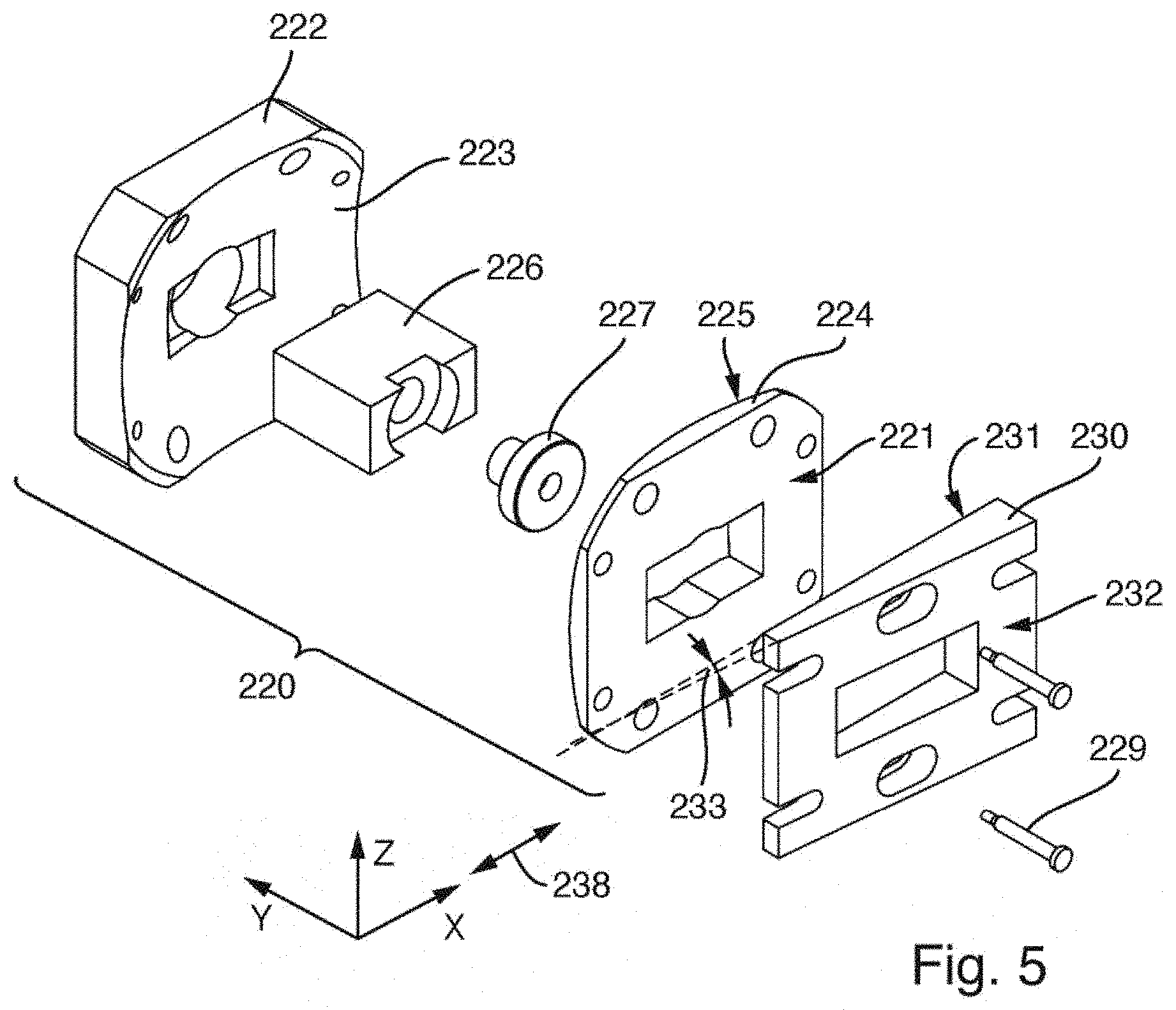
[0012] To solve this problem, the invention provides a honing machine having the features of Claim 1. Advantageous refinements are specified in the dependent claims. The wording of all the claims is incorporated in the content of the description by reference.
[0013] According to one formulation of the invention, a generic honing machine is characterized in that the rotary drive is accommodated in an exchangeable first cartridge and the expansion drive is accommodated in a second cartridge which is exchangeable independently of the first cartridge, wherein the first cartridge is introducible into the first housing portion and the second cartridge is introducible into the second housing portion.
[0014] Here, the expression "cartridge" stands for an exchangeable assembly which combines, in one unit, all components that have to be exchanged during an exchange process, and which has a dedicated housing (cartridge housing). Accordingly, the first cartridge has a first cartridge housing, in which, inter alia, the rotary drive is accommodated, and the second cartridge has a second cartridge housing, in which, inter alia, the expansion drive is accommodated. The result is a modular construction of the spindle unit, in which the mutual alignment of the first cartridge and of the second cartridge and thus of the rotary drive and of the expansion drive can be ensured by way of the installation into the commonly utilized spindle unit housing. Said spindle unit housing serves as a common geometrical reference for the installed components. Additionally, it is also possible for the reference with respect to the components of the linear guide of the stroke drive to be established by means of the spindle unit housing, such that certain alignment operations can be simplified or eliminated.
[0015] The accommodation of the rotary drive and of the expansion drive in mutually independently exchangeable cartridges offers the advantage inter alia that narrow tolerances can be adhered to very easily from a manufacturing aspect. Owing to the narrow tolerances, the renewed setting of the machine geometry after an exchange can generally be omitted. In this way, repair and/or maintenance work is considerably simplified and accelerated and can possibly be performed by well-trained technicians, who need not be specialists with regard to the alignment of the components. By means of the arrangement of the first cartridge and of the second cartridge within the common spindle unit housing, the rotary drive (spindle motor) and the expansion drive can be exchanged independently of one another.
[0016] The first cartridge and/or the second cartridge preferably have a substantially rotationally symmetrical outer contour. Mechanical orientation structures may be provided in order to ensure that the cartridges can be installed into the spindle unit housing only in one particular rotational position.
[0017] In preferred embodiments, it is provided that the spindle unit housing is formed as a monocoque housing in which the first housing portion is formed as a single piece with the second housing portion. In this way, possible alignment-critical interfaces between the housing portions are eliminated. A single-part spindle unit housing may impart additional stability to the spindle unit and offers an invariant geometrical reference of the housing portions, and possibly of the cartridges accommodated therein, with respect to one another. The spindle unit housing may possibly also be assembled from multiple housing parts.
[0018] In principle, it is possible for the design to be configured such that the first cartridge and the second cartridge can be installed into the spindle unit housing from the same side. However, in preferred embodiments, it is provided that the first cartridge and the second cartridge are introducible into the spindle unit housing from opposite sides thereof. In this way, independent dismounting and mounting are made easier. In the case of a vertically oriented spindle unit, the first cartridge, which comprises the spindle motor, may be installed from below, whereas the second cartridge, which comprises the expansion drive, is inserted from above into the spindle unit housing.
[0019] In some embodiments, it is provided that, on an inner side of the first housing portion, there is formed at least one first fitting surface which, in contact with at least one corresponding first fitting surface on the first cartridge, effects a positioning and alignment of the first cartridge in the first housing portion, and, alternatively or in addition, on an inner side of the second housing portion, there is formed at least one second fitting surface which, in contact with at least one corresponding second fitting surface on the second cartridge, effects a positioning and alignment of the second cartridge in the second housing portion. The position and the alignment may be defined by fitting diameters situated on the outer diameter of the cartridges. In some embodiments, it is considered to be particularly advantageous for an internally situated fit to be configured with a smaller diameter than an external fit provided on a flange, such that, during mounting and dismounting, the respective fitting surfaces come into contact with one another only when the respective cartridge has been almost fully inserted into the spindle unit housing, not already at the start of the insertion into the spindle unit housing.
[0020] Furthermore, on the spindle unit housing, there may be formed axial stop surfaces for predefining an axial position of the first cartridge in the first housing portion and of the second cartridge in the second housing portion. In some embodiments, it is provided that, on the cartridges, there are provided outwardly projecting flange portions which abut against associated end surfaces of the spindle unit housing when the corresponding cartridge is inserted into said spindle unit housing and the desired axial installation position has been attained. The respective axial fastening, that is to say the fixing of the axial position of the respective cartridge in relation to the spindle unit housing, can thus be realized by means of a flange with axial screws.
[0021] In many designs, it is relatively easily possible for the expansion drive or the second cartridge to be directly contacted from the outside and thus for the media required for operation (electrical power, possibly an exchange of electrical signals for control and for transmission of encoder signals, fluid media) to be conducted in and conducted out. Since, however, in the case of the first cartridge, contacting from the side of the connection for the honing tool is not possible or is possible only under adverse constraints, the first cartridge should as far as possible also be contacted through the spindle unit housing. For this purpose, in some embodiments, it is provided that connections for possibly present rotary encoders, the electrical connections for the feed of electrical power for the motor coil and/or connections for fluids (coolant for dissipating the motor waste heat, coolant feed line and coolant return line to the machining location, possibly sealing air) should be arranged preferably at that side of the first cartridge which is to face towards the second cartridge.
[0022] In some embodiments, connection problems are resolved in a particularly convenient manner in that, on a side, which is to face towards the second cartridge, of the first cartridge, and on a side, which is to face towards the first cartridge, of a housing portion of the spindle unit housing, there are arranged corresponding connecting elements of at least one plug-type connection for the transfer of liquid or gaseous fluid, electrical power and/or electrical signals. Owing to the configuration as a plug-type connection, the required connection is produced automatically during the assembly of the components, such that no separate assembly steps are required for producing electrical and/or fluidic connections. Owing to the configuration as a plug-type connection, an exchange of the first cartridge is possible much more quickly and easily than if multiple lines had to be individually disconnected and reconnected.
[0023] The cartridge concept can be implemented with different drive types of the rotary drive and/or of the expansion drive. In one refinement, as an expansion drive, a torque motor is provided which is installed directly into the second cartridge housing. In this way, the expansion drive can be configured to be extremely short and thus also lightweight. The torque motor may be coupled to a rotary encoder, preferably to a high-resolution absolute encoder with multiturn capability. The rotating part of the torque motor may drive a threaded spindle in order to generate, from the rotational movement, a linear movement which then acts on the advancing rod running in the interior of the spindle shaft.
[0024] The torque motor is an example of an electric direct drive. As an alternative to the torque motor, the drive may also be some other electric direct drive, for example a plunger coil motor, which requires no threaded spindle or the like to convert the movement direction. It is also possible to use a servomotor as a rotary drive.
[0025] To further facilitate assembly and maintenance and repair work, it is provided in some embodiments that fluid channels for conducting fluid, in particular cooling fluid for the rotary drive, are formed in the cartridge housing of the first cartridge. In this way, the cartridge housing of the first cartridge can be directly cooled, and the heat can be dissipated from the region of the rotary drive via the cartridge housing. In this way, a cooling device on the rotary drive itself can possibly be omitted. This yields the possibility of providing a compact construction of the rotary drive, which can then be dismounted jointly with the first cartridge without the need for a servicing technician to detach hose connections.
[0026] Alternatively or in addition, it may be provided that fluid channels for conducting fluid are formed in the spindle unit housing. It is for example possible for fluid channels to be provided for conducting cooling fluid for the rotary drive. In this way, the spindle unit housing can be directly cooled, and the heat can be dissipated for example from the region of the rotary drive via the spindle unit housing. In this way, it may be possible for a cooling device and/or coolant channels on the first cartridge and/or on the rotary drive itself to be omitted. Alternatively or in addition, fluid channels may be provided for conducting fluid to the honing tool and back from the honing tool.
BRIEF DESCRIPTION OF THE DRAWINGS
[0027] Further advantages and aspects of the invention will emerge from the claims and from the following description of preferred exemplary embodiments of the invention, which are explained below on the basis of the figures:
[0028] FIG. 1 shows an oblique perspective view of a honing machine according to an exemplary embodiment;
[0029] FIG. 2 shows a vertical section through a honing unit arranged on the support structure of the honing machine and components of a rotary table transport system;
[0030] FIG. 3 shows a section along the y-z plane through a setting unit of an alignment system according to an exemplary embodiment;
[0031] FIG. 4 shows a section parallel to the x-y plane through the setting unit from FIG. 3;
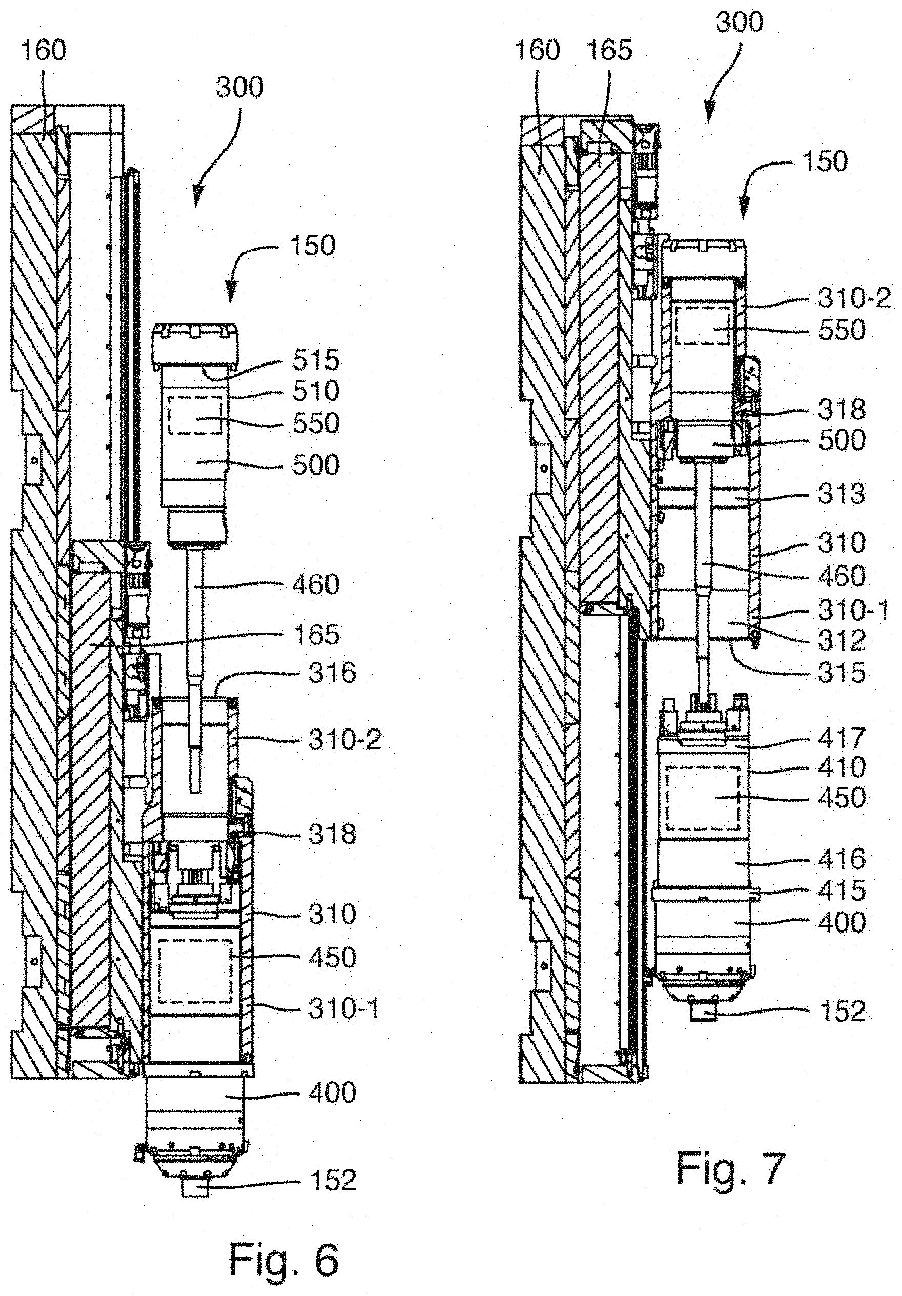
[0032] FIG. 5 shows an exploded illustration of the setting unit of FIGS. 3 and 4;
[0033] FIG. 6 shows the replacement of components of an expansion system in which the expansion drive is arranged in an exchangeable cartridge;
[0034] FIG. 7 shows the replacement of the spindle shaft and of other components of the spindle unit, wherein the rotary drive is arranged in an exchangeable cartridge;
[0035] FIG. 8 shows an oblique perspective view of the cartridge containing the rotary drive, which cartridge, on its top side, has plug connectors for plug-type connections for the electrical and fluidic connection of components of the cartridge; and
[0036] FIGS. 9A to 9D show special features of the available stroke length and stroke positions of the embodiment.
DETAILED DESCRIPTION OF THE EXEMPLARY EMBODIMENTS
[0037] FIG. 1 shows an oblique perspective view of a honing machine 100 according to an exemplary embodiment. FIG. 2 shows a vertical section through a honing unit arranged on the support structure of the honing machine and components of a rotary table transport system. In the configuration shown, the honing machine has only a single honing unit. A second support structure with a second honing unit for machining the same workpieces may be provided.
[0038] The honing machine 100 has a substantially rectangular machine base 110 with a frame and a base plate which is or should be oriented horizontally in the case of a fully set-up honing machine. The rectangular base plate is somewhat longer in the first direction (longitudinal direction) running parallel to the y axis of the machine coordinate system MKS than in the second direction (transverse direction) which is perpendicular thereto and which runs parallel to the x axis of the machine coordinate system. Close to the rear side 114 of the machine base, in the vicinity of one of the longitudinal edges, there is arranged a vertical stand 120, which is fixedly screwed to the machine base. The vertical stand serves as a support structure 120 for a honing unit 130, which is mounted on the support structure in the region of the front side of the latter.
[0039] A major constituent part of the honing unit is a spindle unit 150 in which a spindle shaft 152 is rotatably mounted. To drive the spindle shaft, there is integrated a rotary drive or spindle motor which is integrated into the spindle unit and which can drive the spindle shaft about the spindle axis 155, that is to say about the axis of rotation of the spindle shaft 152, with a predefined rotational speed profile. The spindle shaft 152 has, at a tool-side end 153, which is also referred to as spindle nose, a device (tool receptacle) for the fastening of a honing tool 190.
[0040] The spindle unit 150 is mounted on the top side or front side of a carriage plate 165. The carriage plate is supported by a carriage box 160 which serves as the main support of the honing unit. Between the main support 160, which is formed by the carriage box, and the carriage plate 165 or the spindle unit supported thereby, there is provided a linear guide system (not visible in the illustrations) for guiding a linear stroke movement of the spindle unit 150 relative to the main support 160. In the example, the stroke drive has an electric linear motor with a primary part and a secondary part which are movable relative to one another parallel to the longitudinal direction of the longitudinal guide system (ideally also parallel to the spindle axis 155).
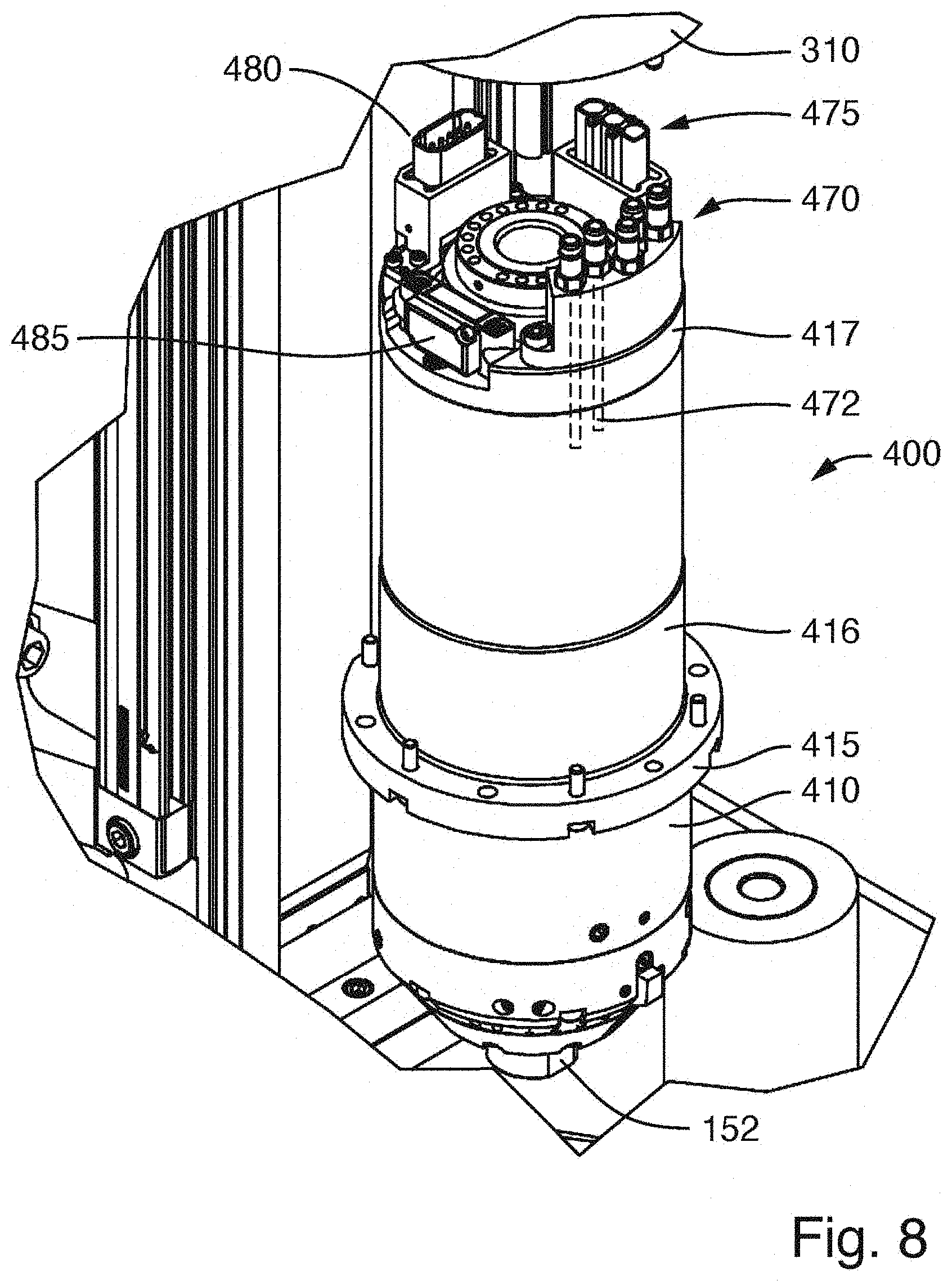
[0041] In the example, the primary part, which is operated with an electrical current, is attached to the carriage plate, or to the spindle unit 150 which is likewise operated with current, whereas a series of permanent magnets is arranged within the main support 160. A reversed arrangement is also possible.
[0042] The linear guide system has guide rails which are attached to the main support 160. The corresponding guide shoes are arranged on the bottom side of the carriage plate 165. There are also embodiments in which the guide shoes, which slide on the guide rails, are fastened to individual fastening surfaces of the spindle unit, without the interposition of a carriage plate which is common to the guide shoes.
[0043] The honing machine 100 is equipped with a workpiece transport system 180 which has a rotary table or a rotary indexing table. In the case of the illustrated rotary table transport system, a horizontally oriented table panel 184 is provided which, by means of a rotary drive arranged under the table panel, can be rotated in predefined angular steps about an axis of rotation 185 which is oriented nominally vertically (parallel to the z direction of the machine coordinate system). On a pitch circle about the axis of rotation 185, there are provided multiple (in the example, six) workpiece receptacles 182 for receiving in each case one workpiece W. During transportation, the table panel rotates through a particular angle (in this case 60.degree.) about the axis of rotation 185, which is positioned fixedly in space, in order to successively arrange in each case one workpiece W in a machining position under the honing unit 130 such that the spindle axis 155 corresponds as closely as possible to the bore axis in the workpiece W. Ideally, all workpiece receptacles are mounted so as to be as far as possible equally spaced apart from the axis of rotation 185 and as far as possible with a uniform circumferential spacing to one another. If multiple honing units or multiple honing stations are served by the rotary table transport system 180, then all honing units must be as far as possible aligned such that, in any transport position, there is as small as possible a spacing between the actual axis of rotation of the spindle motor and the bore axis in the tool. This means that all honing units must be correspondingly aligned in the honing machine.
[0044] The honing unit 130 is fastened by means of two fastening units 210-1, 210-2 to the front side of the stand or of the support structure 120. Here, the fastening units constitute a mechanical connection between the stand 120 (support structure 120), which is fixed with respect to the machine, and the base support 160 of the honing unit 130. The vertical spacing 212, measured in the z direction, between the effective centres of the fastening units 210-1, 210-2 amounts, in the example, to more than 30%, in particular more than 40% and/or less than 90% or less than 80% of the length, measured in the vertical direction, of the main support 160. The fastening units are not arranged at the outer ends of the main support 160 but rather are offset inward. What is particularly advantageous is an arrangement such that the fastening units are positioned such that the guide shoes, which are situated on the carriage plate which supports the spindle unit, have as small a spacing as possible to the fastening units when the spindle unit is situated in a stroke position intended for the machining process. Here, it is possible in particular for the dynamic forces that arise during an oscillating stroke movement to be particularly readily accommodated.
[0045] The fastening units 210-1 and 210-2 simultaneously function as first setting unit 210-1 and second setting unit 210-2 of an alignment system 200, the components of which are arranged at least partially between the support structure 120 and the main support 160. By means of the alignment system 200, it is possible both for the position of the spindle axis 155 to be adjusted in continuously variable and reversible fashion along two mutually perpendicular axes of translation, and for the setting of the orientation (angular attitude) of the spindle axes to be adjusted in continuously variable and reversible fashion in relation to two mutually perpendicular axes of rotation. In this way, it is possible for the spindle unit as a whole to be aligned such that its axis (spindle axis 155) is aligned as closely as possible with the axis of the bore to be machined.
[0046] Each of the setting units 210-1, 210-2 offers exactly two translational setting degrees of freedom. In the case of a first setting degree of freedom, the structural height, measured parallel to the first direction (y direction), of the setting unit can be varied in continuously variable and reversible fashion within certain limits, such that the spacing 214, measured parallel to the first direction, between the support structure 120 and the main support 160 of the honing unit at the location of the fastening unit can be varied. First setting elements are provided for this purpose. In the case of the second setting degree of freedom, it is possible for those components of the setting unit which are fixedly connected to the main support 160 of the honing unit 130 to be displaced in continuously variable and reversible fashion, parallel to the second direction (x direction), relative to those components which are fixedly connected to the support structure 120. Second setting elements are provided for this purpose. There are components which belong both to the first and to the second setting elements and which thus have a dual function (for example a wedge element discussed in more detail further below).
[0047] These two translational setting degrees of freedom, together with the fact that the two setting units 210-1, 210-2 are arranged with a vertical spacing 212 to one another (measured along the z direction or the third direction), make it possible for the position of the spindle axis 155 to be set along two mutually perpendicular axes of translation (parallel to the first direction and parallel to the second direction) and, independently of this, also for the orientation of the spindle axis 155 in relation to two mutually perpendicular axes of rotation (in each case parallel to the first direction and to the second direction) to be set in continuously variable and reversible fashion.
[0048] If, for example, both setting units 210-1, 210-2 are adjusted in terms of their effective structural height such that the spacing 214, measured parallel to the first direction, between support structure 120 and main support 160 is changed by the same magnitude, the result is a change in the position of the spindle axis 155 by parallel displacement in a y-z plane, or a translation of the spindle axis 155 in the first direction. This corresponds to purely a change in position without a change in the orientation.
[0049] If no change in spacing, or a different change in spacing than that at the second setting unit 210-2, is set at the first setting unit 210-1, this results in a change in inclination of the spindle axis 155 within the y-z plane, which leads to a rotation of the spindle axis about a virtual axis of rotation which runs parallel to the second direction (x direction) perpendicular to the y-z plane. The result is thus a change in the orientation.
[0050] If a displacement parallel to the second direction (x direction) by the same displacement travel is set at the first setting unit 210-1 and at the second setting unit 210-2, the result is a parallel displacement of the spindle axis in an x-z plane or a translation of the spindle axis 155 in the second direction. This corresponds to purely a change in position without a change in the orientation.
[0051] If displacement travels of unequal length are set at the first setting unit 210-1 and at the second setting unit 210-2, this results in an adjustment of the inclination of the spindle axis in an x-z plane, which corresponds to a rotation about a virtual axis of rotation which runs parallel to the first direction.
[0052] The spatial attitude of the virtual axes of rotation that possibly arise is not fixed but rather varies in a manner dependent on the ratios of the variations performed at the two setting units.
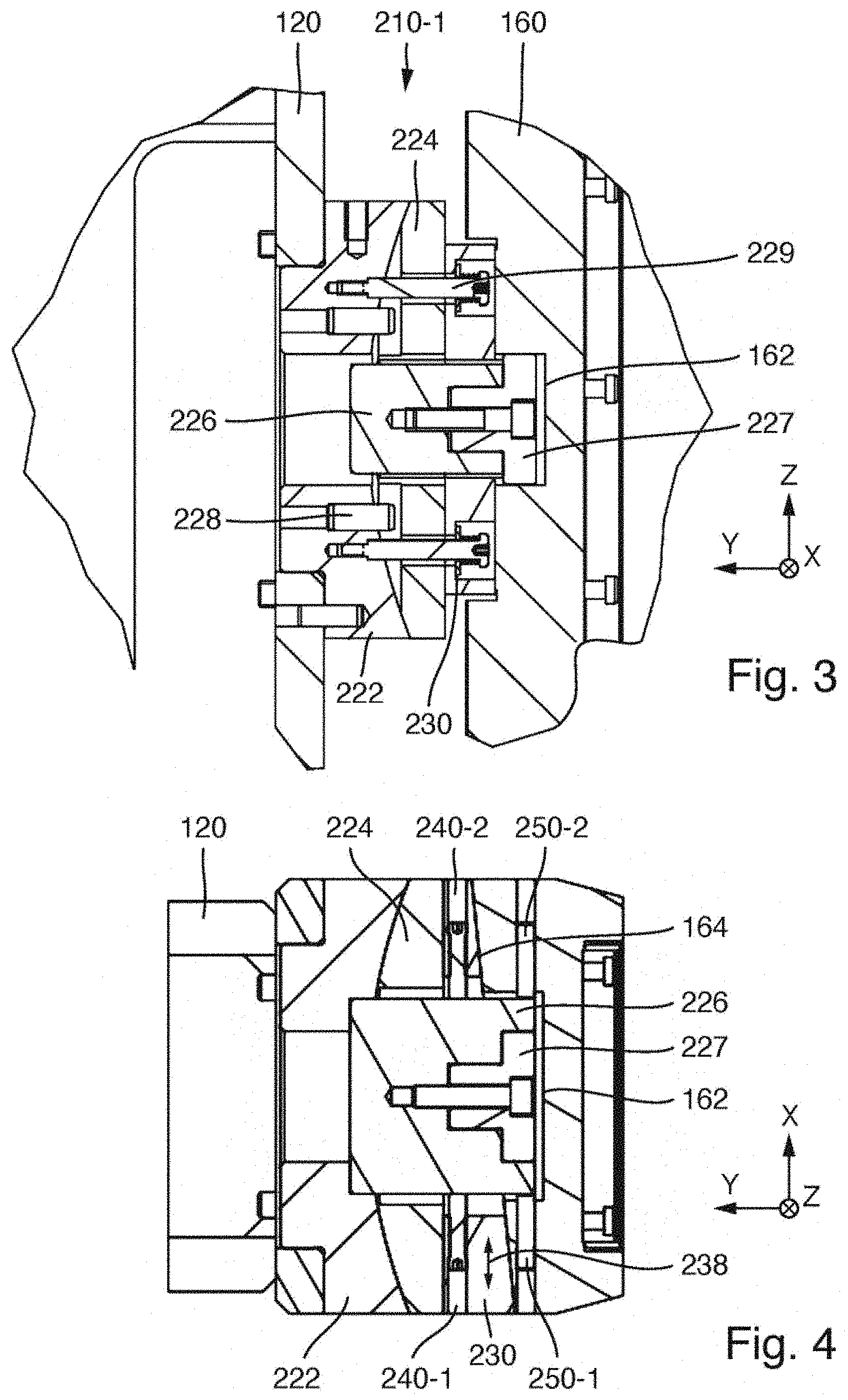
[0053] Details of the construction of the first setting unit 210-1 or of the first fastening unit 210-1 of the alignment system 200 will now be discussed in more detail below with additional reference to FIGS. 3 to 5. Here, FIG. 3 shows a section along the y-z plane through the setting unit, FIG. 4 shows a section parallel to the x-y plane, and FIG. 5 shows an exploded illustration of the first setting unit 210-1. The second setting unit 210-2 may be of identical or virtually identical construction.
[0054] The setting unit 210-1 comprises a base element 220 which is composed of multiple components and which is designed for being mounted fixedly on the support structure 120 of the honing machine or on an adapter unit which is connected fixedly to the support structure. Furthermore, a wedge element 230 is provided which has a planar first wedge surface 231 facing towards the base element 220 and has a planar second wedge surface 232 which, in the assembled state, faces toward the main support 160. The wedge surfaces 231, 232 of the relatively flat wedge enclose a wedge angle 233 of approximately 5.degree. to 6.degree.. In the assembled state, the planar first wedge surface 231 lies areally against a planar sliding surface 221, facing towards said first wedge surface, of the base element 220. A relative displacement of the wedge element 230 relative to said sliding surface 221 of the base element along a displacement direction 238 running parallel to the x direction (second direction) is provided by the construction, whereas relative movements in other directions are prevented by the construction. The actuating devices which are provided for actuating this relative displacement and which serve for displacing the wedge element 230 in the displacement direction and for positioning the wedge element in a target position will be discussed in more detail further below.
[0055] The base element 220 includes a spherical socket 222, which serves as a basis for the fastening unit and is provided for being fixedly screwed to the support structure of the honing machine at the fastening position provided for it. In some embodiments, an adapter unit with suitable assembly interfaces is also interposed between the spherical socket and the support structure. A cylindrical pin may be used for the orientation of the spherical socket 222 in terms of attitude on the support structure 120 or on an adapter provided for connecting to the support structure. Said cylindrical pin can define the rotational position of the spherical socket in a fitting bore of the support structure or of an adapter.
[0056] On the side facing towards the wedge element, there is formed a spherically curved sliding surface 223. In the assembled state, a spherical disc 224 lies in the spherical socket 222. Said spherical disc has, on the side facing towards the spherical socket, a convex spherical sliding surface 225 corresponding with the sliding surface 223, and has, on the side facing towards the wedge element, the planar sliding surface 221. A free rotation of the spherical disc 224 in the spherical socket 222 is prevented by virtue of the spherical socket having two cylindrical pins 228 which run in a groove in the spherical disc 224. Thus, only a limited rotation about an axis of rotation running parallel to the second direction is possible.
[0057] During the assembly process, the wedge element 230 is placed onto the spherical disc 224. Said wedge element may also be displaced laterally in the displacement direction (parallel to the x direction) in order to be able to set the structural height, measured parallel to the y direction, of the setting element in continuously variable and reversible fashion. Firstly, the angle of the wedge element 230 should be shallow enough that it lies in the range of self-locking. Here, this means that a change in load on the wedge element should not trigger any lateral displacement of the wedge element. Secondly, however, the angle of the wedge element should also be steep enough that a sufficient range of adjustment in the height of the wedge element is present with the available lateral displacement travel of the wedge element 230. In the exemplary embodiment, the wedge angle 223 is dimensioned such that there is an integer ratio between the lateral displacement of the wedge element and the resulting change in height of the fastening unit or of the setting unit. A wedge with a corresponding ratio of 1:10 has proven highly suitable, such that a displacement by 1 mm causes a change in height by 0.1 mm.
[0058] Two tension anchors 229 are provided for facilitating the handling of the components during the assembly process. These each exert a slight pressure on the wedge element 230 via a helical spring, such that said wedge element is supported on the spherical disc 224 and thus prevents the wedge element from lifting off the spherical disc during the assembly process.
[0059] In the fixedly installed spherical socket 222, there is fixedly installed a substantially cuboidal holding block 226. In the holding block, there is seated a bearing bolt 227 on which the main support 160 can be supported during the mounting of the honing unit 130 onto the fastening unit 210-1, in order, during the assembly process, to compensate for the mass of the honing unit with respect to the Earth's gravitational force. The bearing bolt 227 has a circular outer contour at its side facing towards the honing unit. The main support 160 has, on its side facing towards the fastening unit, a rectangular pocket or recess 162 for receiving the support bolt, which in the received state ideally forms linear contact (or, in the case of relatively great angles of inclination, punctiform contact) with the rectangular pocket, such that no constraint is imparted even in the event of inclination of the honing unit.
[0060] On the upper fastening unit 210-1, the support bolt 227 is fitted relatively tightly in said pocket on the main support 160, in order to fix the position of the honing unit in the honing machine relatively accurately already during the assembly process. On the lower fastening unit 210-2, the pocket on the main support 160 of the honing unit is somewhat larger, such that no constraint is imparted to the honing unit here either.
[0061] In the wedge element 230, on opposite sides of the polygonal cutout provided for the passage of the holding block 226, there are provided threaded bores which are oriented substantially parallel to the second direction. Into the threaded bores, there are screwed setting screws 240-1, 240-2 which serve as actuating elements of an actuating device for displacing the wedge element 230 in the displacement device 238. By means of these setting screws, the wedge element can be displaced against the holding block 226 (which is attached fixedly with respect to the machine) in the displacement direction 238. The height adjustment of the fastening element and thus the spacing adjustment (in the y direction) between support structure and main support of the honing unit at location of the setting unit is effected by displacement of the wedge element. When the desired target position has been attained, the wedge element automatically holds this position owing to self-locking. The wedge element can however be additionally fixed in this position by tightening of the setting screws which act against one another.
[0062] On the main body 160, at the location provided for the attachment of the fastening unit or setting unit 210-1, there is formed a planar oblique surface 164 which in the assembled state interacts, as a sliding surface, with the second wedge surface 232. In the main support 160 of the honing unit, there are furthermore formed threaded bores which run parallel to the x direction and in which setting screws 250-1, 250-2 are seated. Said setting screws are likewise supported on the holding block 226 (which is installed fixedly with respect to the machine). A displacement of the main support 160 of the honing unit relative to the support structure 120, which is fixed with respect to the machine, parallel to the displacement direction 238 is possible by actuation of the setting screws 250-1, 250-2. Here, the planar second wedge surface 232 and the oppositely situated planar oblique surface 164 on the main support slide on one another. Since this is associated with a minimal change in spacing in the y direction, the setting screws 240-1, 240-2 should also be adjusted to the same extent for the purposes of compensation.
[0063] A configuration such that each rotation of the setting screw results in a fixed extent of the displacement is advantageous. For example, in the case of a thread pitch of 1 mm, one full rotation of the setting screw 250-2 results in a displacement of 1 mm. By re-measuring the positions of the parts with respect to one another, the respectively set position can be read off, and the adjustment travel that is still required can be estimated.
[0064] The basic setting of the fastening units 210-1, 210-2 is the theoretical centre, such that, in this position, in the absence of all manufacturing tolerances of the honing machine, the axis of the spindle motor, that is to say the spindle axis 155, would run exactly in alignment with the bore axis in the workpiece. Proceeding from this central position, both the height of the setting units parallel to the first direction (y direction) and also the lateral offset by relative displacement parallel to the second direction (x direction) can be reversibly set independently of one another by means of the setting screws 240-1, 240-2 and 250-1, 250-2 respectively. A lateral displacement parallel to the x direction arises here from the setting screws 250-1, 250-2 in the main support. The setting of the height of the fastening unit in the y direction arises from the setting screws or forcing-off screws 240-1, 240-2 in the wedge element 230.
[0065] In order to vary the position of the honing unit relative to the bore axis in the workpiece, the upper setting unit 210-1 and the lower setting unit 210-2 are adjusted in each case in the same direction by the same setting travel. In order to adjust the angular position of the unit, the upper setting unit and the lower setting unit are adjusted in opposite directions and/or to different extents. In the case of the fastening units being set in opposite directions and/or to different extents, an angular offset between those wedge surfaces of the wedge elements which lie on the spherical segments can occur owing to the different heights of the two setting units. This angular offset can be compensated by means of small compensation movements of the spherical discs in the spherical sockets. Thus, the spherical bearings which are integrated into the fastening units 210-1, 210-2 and which have the complementary curved sliding surfaces serve as an angle compensation device for automatically compensating angular offsets, and stresses possibly caused as a result, in the case of adverse setting conditions of the setting units. In the example, the radius of curvature of the spherical sliding surfaces 223, 225 is selected such that (in the case of the wedge element being set into its central position) the sphere central point lies on the axis of rotation of the spindle motor, that is to say on the spindle axis 155. Thus, possible compensation movements do not have an effect on the position and orientation of the spindle axis.
[0066] A method for setting the machine geometry with alignment of the spindle axis in relation to the bore axis of the bore that is to be honed may for example progress as follows.
[0067] Firstly, the fastening units 210-1, 210-2 which serve as setting units are fastened at their intended positions to the front side of the support structure by means of screws. Here, the wedge elements and the spherical discs are each brought into a central position.
[0068] The honing unit is subsequently fitted by being mounted at the top and bottom on the bearing bolts 227. The main support 160 of the honing unit 130 is then brought into a central position.
[0069] For an alignment operation, as long as possible a cylindrical geometry with reference to the workpiece receptacle or to the transport system should be provided on sides of the workpiece receptacle. For example, a master cylinder may be installed as an alignment aid at the location of a workpiece receptacle of the rotary table transport system. The cylindrical bore in the master cylinder thus represents the bore axis in the workpiece and produces the reference to the transport system. This step may be performed before or after the fitting of the honing unit on the support structure.
[0070] Thereafter, the parallelism of the axis of rotation of the spindle motor, that is to say the parallelism of the spindle axis with respect to the central longitudinal axis of the master cylinder, can be set for example by setting of the setting units in opposite directions and/or to different extents. Here, it is preferably firstly the case that the lateral setting (parallel to the displacement direction) is performed by means of the setting screws in the main support, and then the frontal setting is performed by displacement of the wedge elements.
[0071] Thereafter, the master cylinder can be dismounted, in order to measure a possible position offset of the spindle axis with respect to the setpoint position directly at those bores of the transport system in which the workpiece receptacles will later be installed.
[0072] If these measurements yield that a position offset is still required, then the position of the axis of rotation of the spindle motor with respect to the bore axis of the workpiece is set by adjustment of the setting elements in the same directions to equal extents. Here, too, it is preferably the case that firstly the lateral position (position in the x direction) is set and subsequently the frontal position (position along the first direction or y direction) is set.
[0073] When the desired target position and target orientation have been attained with sufficient accuracy, then the setting screws of the setting units are tightened without further displacement of the components thereby actuated, in order to fix the relative positions assumed.
[0074] The support structure may, as shown, be for example a vertical stand, which possibly supports only a single honing unit. A honing machine may have two or more such stands. The support structure may also be a column, on the periphery of which multiple holding units may be mounted in a circumferentially offset manner (cf. DE 20 2011 003 069 U1). Instead of the direct mounting of the fastening units on the support structure, as illustrated, an indirect fastening by means of an adapter provided for connecting to the support structure is also possible.
[0075] Special features of the construction of a spindle unit 300 which is provided in some embodiments will now be described on the basis of FIGS. 6 to 8. The spindle unit 150 of the exemplary embodiments described above may be of identical construction to the spindle unit 300 described below. It is however also possible for the spindle unit 150 to have a different construction than the spindle unit 300 described here. Aside from the spindle unit, the illustrated components are denoted by the same reference designations as in the preceding examples.
[0076] The spindle unit 300 has a modular construction. The spindle unit housing 310 is constructed as a single-piece component and is also referred to here as a monocoque housing. The substantially tubular component, which is open at both sides, has a first housing portion 310-1, which accommodates the rotary drive 450, and a second housing portion 310-2, which is formed in one piece with said first housing portion and which has a smaller inner diameter than the first housing portion 310-1 and which is provided for accommodating the expansion drive 550.
[0077] The rotary drive 450 is arranged in an exchangeable first cartridge 400 and is mounted on the interior of the substantially rotationally symmetrical cartridge sleeve 410 of the first cartridge 400. The expansion drive 550 is arranged in a second cartridge 500 and is mounted within the cartridge housing 510 of the second cartridge.
[0078] The first cartridge 400 is insertable into the first housing portion 310-1 from below. Independently of this, the second cartridge 500 with the expansion drive is insertable from above into the second housing portion 310-2. The expansion drive is coupled to an axially movable advancing rod 460 which, during the assembly of the spindle unit, is introduced into an inner passage bore of the spindle shaft 152 and, during the operation of the honing machine, acts on an axially displaceable expansion cone which is arranged in the interior of the honing tool.
[0079] FIG. 6 shows a configuration in which the first cartridge 400 (with rotary drive 450) has been installed into the spindle unit housing 310 so as to be ready for operation, whereas the second cartridge 500 with the expansion drive 550 has been removed in an upward direction. FIG. 7 shows a configuration in which the second cartridge 500 with expansion drive 550 has been introduced into its associated second housing portion 310-2, whereas the first cartridge 400 with the rotary drive 450 has been removed from the spindle unit housing in a downward direction.
[0080] A comparison of FIGS. 6 and 7 shows that the removal of the two cartridges or the installation thereof is possible at opposite sides without a large structural space requirement at the sides, because, for the removal or for the installation of the second cartridge 500, the carriage 165 which is displaceable on the main support 160 can be moved downwards, whereas, for the removal or for the installation of the first cartridge 400, the carriage 165 with the spindle unit housing 310 can move upwards, such that, in a downward direction, there remains sufficient free space for the removal of the first cartridge 400 without the risk of a collision with the transport system or with workpiece holding devices.
[0081] The single-piece spindle unit housing 310, which may be produced for example from a torsionally resistant aluminium alloy or from a fibre composite material, serves as a mechanical reference for the mutual coaxial alignment of the two carriages 400, 500 and of the components contained therein and also as a mechanical reference for establishing the correct alignment of said components of the spindle unit 300 in relation to the linear guide system of the stroke drive.
[0082] To ensure that each of the cartridges is installed in the correct alignment and in the correct axial position in relation to the associated housing portion of the spindle unit housing, corresponding fitting surfaces are formed on the outer sides of the respective cartridges and the inner sides of the associated housing portions. In FIG. 7, the centring fitting surfaces of the first housing portion 310-1 for receiving the first cartridge 400 can be clearly seen. Directly adjoining the bottom end side 315 of the spindle unit housing 310, a rotationally symmetrical lower fitting surface 312 is formed on the inner side of said spindle unit housing. A rotationally symmetrical upper fitting surface 313 is formed with a spacing in an upward direction, that is to say in the interior of the first housing portion 310-1.
[0083] An outwardly projecting flange 415 is formed in the lower third on the cartridge housing 410 of the first cartridge 400. The upwardly pointing flange surface of said flange serves as an axial stop surface for an abutment against the end side 315 of the spindle unit housing and thus defines the axial position of the installed cartridge. Directly above the flange 415, there is situated a wide rotationally symmetrical fitting surface 416 which fits with the fitting surface 312. Above this, with a spacing, there is situated a further fitting surface 417, which fits with the upper fitting surface 313. The internally situated fit between the fitting surfaces 313 and 417 is formed with a smaller diameter than the external fit with the fitting surfaces 416 and 312 in the vicinity of the flange 415. It can thus be achieved that, during the mounting process, the respective fitting surfaces come into contact with one another only when the first cartridge 400 has been almost fully inserted into the spindle unit housing or the associated housing portion, and not already at the start of the insertion into the spindle unit housing.
[0084] A corresponding solution is also provided for the installation of the second cartridge 500 in the second housing portion 310-2. There, too, there are two fitting surface pairs, which are situated so as to be spaced apart from one another, and, on the widened head of the second cartridge 500, a stop surface 515 which, during the axial insertion of the second cartridge 500, abuts against the upper end side 316 of the spindle unit housing 310 and thus defines the axial position of the second cartridge 500 in the spindle unit housing. Thus, the correct alignment and axial position of the cartridges is set without further alignment work once the insertion of the cartridges has been completed during the mounting on the spindle unit housing.
[0085] One particular challenge consists in providing, in the spindle unit 300, suitable electrical and fluidic connections of the components installed in the first cartridge 400. Whereas the components of the second cartridge 500 which accommodates the expansion drive 550 can be contacted relatively easily directly from above by means of suitable connectors, contacting of the components (for example rotary drive) provided in the first cartridge 400 from below, that is to say from the side at which the honing tool is coupled on, is not possible or is possible only with restrictions.
[0086] In the exemplary embodiment, connection problems for the internal components of the first cartridge 400 are resolved by virtue of connecting elements of suitable plug-type connections being attached to the upper side of the first cartridge 400, that is to say to the inner side which is to face towards the second cartridge 500. Said connecting elements cooperate with corresponding connecting elements of a plug-type connection on a housing portion 318 of the spindle unit housing 310 at the stepped transition from the relatively large diameter in the first housing portion 310-1 to the relatively small diameter at the second housing portion 310-2.
[0087] In the exemplary embodiment of FIG. 8, there are automatically sealing male plug connector components of fluid connecting elements 470 for the introduction or discharge of liquid or gaseous fluids. Two of the fluid plug connectors serve for the feed and discharge of cooling liquid for the cooling of components arranged within the first cartridge 400, in particular of the rotary drive. These plug-type connectors are connected to coolant channels 472 which run in the interior of the wall of the cartridge housing 410 of the first cartridge and which are indicated here merely by dashed lines. Coolant channels may for example run in helical fashion within the cartridge housing. It is also possible to construct a channel network with partially axially running coolant channel portions and transverse connections. Two further fluid connecting elements may serve for the feed and discharge of cooling lubricant to the honing tool and from the honing tool. Gaseous fluids may also be connected. For example, a connector may be provided for conducting sealing air through the cartridge housing 410 of the first cartridge 400 to an outlet on the tool side of the first cartridge.
[0088] The electrical plug contacts 475 serve for the supply of electrical power to the rotary drive 450 and the transmission of information relating to the rotary drive, for example from temperature sensors. The electrical connections 480 serve for the transmission of signals from encoders installed in the first cartridge 400, for example of a rotary encoder of the rotary drive, for the purposes of controlling the honing machine. The rotary encoder may be composed of a static and a rotating part, wherein the static part functions as a measuring head 485.
[0089] The associated plug sockets are attached to the downwardly pointing side of the housing portion 318 at the stepped transition between the relatively large inner diameter of the first housing portion 310-1 and the relatively small inner diameter of the second housing portion 310-2. The electrical and fluid connections are automatically produced in the final phase of the insertion, when the first cartridge 400 is inserted, in the correct rotational position, into the associated first housing portion 310-1. To ensure that the first cartridge can be introduced, and inserted as far as the stop, only in a single rotational position, a corresponding structure is provided.
[0090] Further special features of the machine concept of the exemplary embodiment will now be discussed in conjunction with FIGS. 9A to 9D. The honing machine may be used for the honing of workpieces of very different workpiece heights and bore lengths without the need for the honing machine to be converted for this purpose. FIGS. 9A and 9B show the machining of a workpiece W1, the workpiece height of which corresponds to the maximum height WHO of a workpiece height range taken into consideration in the design. The honing machine can thus machine workpieces up to this workpiece height.
[0091] FIGS. 9C and 9D show the machining of workpieces W2 which have a smaller workpiece height and which have only a relatively short bore for machining.
[0092] A relatively long honing tool 190-1 is accordingly required for the machining of the tall workpiece W1, whereas a relatively short honing tool 190-2 can be used for the machining of the short bore in the relatively short workpiece W2, which makes it possible to realize small concentricity errors and thus high levels of machining quality.
[0093] In the design of the honing unit 130, attention is paid inter alia to an optimum axial mounting position of the main support 160 or of the carriage box 160 on the support structure 120. Here, the main support 160 is attached to the support structure 120 such that an end 166 close to the workpiece, that is to say the bottom edge 166 of the carriage box or of the main support 160, lies with a spacing above the upper boundary WHO, facing towards the spindle unit, of the workpiece height range.
[0094] It is thus possible, during rotation of the rotary table or of the table panel 184 thereof about the rotary table axis 185, for even the tallest workpieces W1 to move through below the main support 160 without collision, if the spindle unit 150 has been retracted sufficiently far upwards. In this regard, FIG. 9A shows a situation in which the spindle unit 150 has been moved into its upper end position. In the example, said spindle unit is designed such that, even in the case of the longest honing tool 190-1 being used, the tip thereof, which faces towards the workpiece, extends at most as far as the level (illustrated by means of a dashed line) of the lower edge 166 of the main support, but no further in the direction of the workpiece. In this way, firstly, free transport of the workpieces is ensured in the case of a retracted spindle unit (FIG. 9A), and secondly, the stroke length of the linear movement of the spindle unit is so great that, when the spindle unit has been moved down, the long honing tool 190-1 can machine the bore over its entire length with an oscillating stroke. In this regard, FIG. 9B shows the spindle unit at its bottom dead centre, close to the workpiece, of the oscillating stroke movement.
[0095] It is important here that the spindle unit 150 can also be moved further downwards in the direction of the workpiece if required, as will be discussed in more detail on the basis of FIG. 9D.
[0096] It can be seen from FIG. 9C that the workpiece-facing end, or the bottom edge 166, of the main support is arranged far above the movement path of the relatively short workpieces W2, such that the workpieces can be transported around the rotary table axis 185 into their respective machining position below the spindle unit without colliding with the main support.
[0097] In the case of a short honing tool 190-2 being used for machining the short bore of a short workpiece, the spindle unit 150 must be moved relatively far downwards or in the direction of the workpieces. Here, FIG. 9D shows a position of the spindle unit close to the bottom dead centre of the oscillating movement of the holding tool 190-2 in the bore of the short workpiece W2. It can be clearly seen in this illustration that, in this position, close to the workpiece, of the stroke movement of the spindle unit 150, the tool-side end 153 of the spindle shaft 152, that is to say the spindle nose 153 with the device for receiving the tool, is moved downwards beyond the lower end 166 of the main support and thus lies closer to the workpiece height range than that end 166 of the main support which is close to the workpiece. In the working position of FIG. 9D, it can also be clearly seen that the tool-side end 153 of the spindle shaft projects in a downward direction, or in the direction of the workpieces, beyond the workpiece-side end of the carriage plate 165 to the workpiece side. The projecting length 167, that is to say the length by which the spindle nose 153 projects beyond the workpiece-side end of the main support 160, may for example amount to 10% or more or 25% or more of the total length of the spindle unit between spindle nose and upper end of the expansion device.
[0098] Furthermore, owing to the use of electric direct drives for the rotary drive and the expansion drive, the spindle unit 150 is so short in an axial direction, that is to say parallel to the spindle axis, that, even in the stroke position furthest remote from the workpiece (FIG. 9A), the upper end of the spindle unit 150 does not project beyond the upper end of the main support 160. The machine roof 105 can thus be attached directly above the upper end of the main support 160, whereby an enclosure of the honing machine which is compact even in a height direction is made possible.
[0099] Tests performed by the inventor with regard to favourable dimensioning proportions have found that, for many practically relevant applications or workpieces, the workpiece height range may lie in the range from 250 mm to 500 mm, in particular in the range from 250 mm to 400 mm. The upper boundary WHO of the workpiece height range may thus lie for example 250 mm to 500 mm above a reference plane, wherein the reference plane is the plane on which the workpiece holding devices are mounted (that is to say for example the top side of the table panel). The bottom edge 166 of the main support may lie one or a few mm above this upper boundary. Expedient stroke lengths may lie for example in the range from 450 mm to 700 mm, in particular in the range from 500 mm to 650 mm. Expedient stroke lengths may lie for example in the range from 150 mm to 900 mm, in particular in the range from 180 mm to 850 mm (likewise in relation to the reference plane measured above). Expedient lengths of the main support may lie for example in the range from 1000 mm to 1500 mm, in particular in the range from 1100 mm to 1400 mm. Expedient axial lengths of the spindle unit (measured from the spindle nose to the top side of the spindle unit housing) may lie for example in the range from 500 mm to 900 mm, in particular in the range from 600 mm to 800 mm. Typical tool lengths may lie for example in the tool length range from 100 mm to 150 mm (for the relatively short honing tools) up to 350 to 600 mm (for the relatively long honing tools).
[0100] Considering the structurally possible projecting length 167 of the spindle nose beyond the bottom edge 166 of the main support, this may lie for example in the range from 20% to 40% of the stroke length, in particular in the range from 25% to 35% of the stroke length. The upper boundary of the workpiece height range may for example amount to 50% to 75% of the stroke length, in particular 60% to 70%. The stroke length may for example lie in the range from 70% to 90% of the length of the spindle unit. Deviations from these dimensions and dimension proportions are self-evidently possible and may be expedient in particular cases.
* * * * *
D00000
D00001
D00002
D00003
D00004
D00005
D00006
D00007
XML
uspto.report is an independent third-party trademark research tool that is not affiliated, endorsed, or sponsored by the United States Patent and Trademark Office (USPTO) or any other governmental organization. The information provided by uspto.report is based on publicly available data at the time of writing and is intended for informational purposes only.
While we strive to provide accurate and up-to-date information, we do not guarantee the accuracy, completeness, reliability, or suitability of the information displayed on this site. The use of this site is at your own risk. Any reliance you place on such information is therefore strictly at your own risk.
All official trademark data, including owner information, should be verified by visiting the official USPTO website at www.uspto.gov. This site is not intended to replace professional legal advice and should not be used as a substitute for consulting with a legal professional who is knowledgeable about trademark law.