An Exercise Apparatus
Davis; Glen ; et al.
U.S. patent application number 15/733342 was filed with the patent office on 2021-04-01 for an exercise apparatus. The applicant listed for this patent is Goprogym Limited. Invention is credited to Glen Davis, Ricky Lee.
| Application Number | 20210093912 15/733342 |
| Document ID | / |
| Family ID | 1000005278628 |
| Filed Date | 2021-04-01 |


View All Diagrams
| United States Patent Application | 20210093912 |
| Kind Code | A1 |
| Davis; Glen ; et al. | April 1, 2021 |
An Exercise Apparatus
Abstract
The invention relates to an exercise apparatus 10. The exercise apparatus 10 comprises a first upstanding support. The exercise apparatus also comprises a pair of arms. Each arm has a first end and a second end. Each arm, towards its first end, is pivotably connected to the first support at a point which is spaced from the floor. Each arm comprises a second end remote from the first end which connects to the first support. Each arm has a handle, to enable manual lifting of the arms. Each arm comprises a mass arranged thereon. The position of the mass is movable along the arm.
| Inventors: | Davis; Glen; (Birmingham, West Midlands, GB) ; Lee; Ricky; (Birmingham, West Midlands, GB) | ||||||||||
| Applicant: |
|
||||||||||
|---|---|---|---|---|---|---|---|---|---|---|---|
| Family ID: | 1000005278628 | ||||||||||
| Appl. No.: | 15/733342 | ||||||||||
| Filed: | August 13, 2018 | ||||||||||
| PCT Filed: | August 13, 2018 | ||||||||||
| PCT NO: | PCT/IB2018/056091 | ||||||||||
| 371 Date: | July 2, 2020 |
| Current U.S. Class: | 1/1 |
| Current CPC Class: | A63B 2225/093 20130101; A63B 21/0616 20151001; A63B 21/4035 20151001 |
| International Class: | A63B 21/06 20060101 A63B021/06; A63B 21/00 20060101 A63B021/00 |
Foreign Application Data
| Date | Code | Application Number |
|---|---|---|
| Aug 11, 2017 | CN | 201721008921.8 |
| Sep 21, 2017 | GB | 1715235.6 |
Claims
1. An exercise apparatus comprising a first upstanding support, the exercise apparatus also comprising a pair of arms, each arm has a first end and a second end, each arm, towards its first end, is pivotably connected to the first support, each arm comprising a second end remote from the first end which connects to the first support, wherein each arm has a handle, to enable manual use of the arms.
2. An exercise apparatus, independent of any previous claim or dependent on claim 1, the exercise apparatus comprising a first upstanding support, the exercise apparatus also comprising a pair of arms, each arm has a first end and a second end, each arm, towards its first end, is pivotably connected to the first support at a point which is spaced from the floor, each arm comprising a second end remote from the first end which connects to the first support, wherein each arm has a handle, to enable manual use of the arms, wherein each arm comprises a mass arranged thereon, and the position of the mass is movable along the arm.
3. An exercise apparatus according to claim 2, wherein the exercise apparatus comprises an adjustable clamp to temporarily fix the position of the mass at different positions along the length of the arm.
4. An exercise apparatus according to claim 2 or 3, wherein the masses are sleeve shaped.
5. An exercise apparatus, independent of any previous claim or dependent on claim 1, the exercise apparatus comprising a first upstanding support, the exercise apparatus also comprising a pair of arms, each arm has a first end and a second end, each arm, towards its first end, is pivotably connected to the first support at a point which is spaced from the floor, each arm comprises a holder for a mass, each arm comprising a second end remote from the first end which connects to the first support, wherein each arm has a handle, to enable manual use of the arms.
6. An exercise apparatus according to any one or more of the preceding claims, wherein the connection between the arms and the first upstanding support allows the arms to move up and down, and horizontally.
7. An exercise apparatus according to any one or more of the preceding claims, wherein each handle comprises a multi way handle.
8. An exercise apparatus according to claim 7, wherein each multi way handle comprises a three way handle.
9. An exercise apparatus according to claim 8, wherein each arm has a main shaft, and each three way handle comprises a first handle part, a second handle part, and a third handle part, and for each arm, and the shaft, the first handle part, the second handle part, and the third handle part are all arranged in approximately the same plane.
10. An exercise apparatus according to claim 9, wherein for each arm, the shaft is spaced from the first handle part by about 90 degrees, the first handle part is spaced from the second handle part by about 90 degrees, the second handle part is spaced from the third handle part by about 90 degrees, and the third handle part is spaced from the shaft by about 90 degrees.
11. An exercise apparatus according to any one or more of the preceding claims, wherein the handles if just one pair of handles, or at least one of the pairs of handle parts of the multi way handles if the handles comprises multi way handles, comprises a sleeve that is rotatable relative to an underlying supporting part of the arm.
12. An exercise apparatus according to any one or more of the preceding claims, wherein the exercise apparatus comprises a second upstanding support, spaced from the first upstanding support.
13. An exercise apparatus according to claim 12, wherein the exercise apparatus comprises a pair of fixed rests for the arms, the fixed rests extending at least partly horizontally from the second support.
14. An exercise apparatus according to claim 13, wherein each rest is connected to the second support in such a way that upper surfaces of each rest are inclined at the same angle as the angle of inclination of the arm which it supports.
15. An exercise apparatus according to any one or more claim which depends on claim 12, wherein the exercise apparatus comprises at least one pair of detachable rests for the arms, the rests extending at least partly horizontally from the second support.
16. An exercise apparatus according to claim 15, wherein each rest of the first pair of detachable rests is connected to the second support in such a way that upper surfaces of each rest are inclined at the same angle as the angle of inclination of the arm which it supports.
17. An exercise apparatus according to claim 16, wherein first pair of detachable rests fitted to second support by lug and slot arrangement, and the angle of the slot varies with the height up the second support.
18. An exercise apparatus according to any one or more of the preceding claims which depends on claim 15, wherein the upper surface of the detachable rests comprises a series of cavities, each of the cavities being defined by successive ridges.
19. An exercise apparatus according to any one or more of the preceding claims which on claim 15, wherein the exercise apparatus comprises a first pair of detachable rests for the arms and a second pair of detachable rests for the arms.
20. An exercise apparatus according to any one or more of the preceding claims which depends on claim 13 and claim 15, wherein the detachable rests are arranged above the fixed rests.
Description
[0001] The invention relates to an exercise apparatus. In particular, the invention relates to a multi function exercise apparatus.
[0002] A problem with known exercise apparatus is that they tend to be designed to perform a single function.
[0003] An aim of the present invention is to provide an improved exercise apparatus and/or an exercise apparatus with greater functionality and/or at least an alternative exercise apparatus.
[0004] According to a first aspect of the invention there is provided an exercise apparatus in accordance with claim 1.
[0005] A separate aim of the present invention is to provide an alternative exercise apparatus.
[0006] According to a second aspect of the invention there is provided an exercise apparatus in accordance with claim 2.
[0007] A further separate aim of the present invention is to provide a further alternative exercise apparatus.
[0008] According to a third aspect of the invention there is provided an exercise apparatus in accordance with claim 5.
[0009] Other optional and preferred features of the invention are set out in the dependent claims, and the description, below. The features of one aspect of the invention can be combined in any complimentary manner, with one or more features of another aspect of the invention, the dependent claims, and/or with one or more features of the description, where such a combination of features would provide a working embodiment of the invention.
[0010] In this way, a multi function exercise apparatus is provided. In this way, an exercise apparatus with means of varying the effective weight of the arm by merely moving weights, rather than adding or subtracting weights, is provided. In this way, an exercise apparatus with interchangeability in the arms is provided. In this way, an exercise apparatus with interchangeability in the rests is provided. In this way, an exercise apparatus with variability in terms of handle is provided.
[0011] Various exercise apparatus in accordance with the invention will now be described, by way of example only, with reference to the accompanying drawings, in which,
[0012] FIG. 1 is a perspective view of an exercise apparatus,
[0013] FIG. 2 is a plan view of part of the exercise apparatus, detailing amongst other things an arm supporting member of the exercise apparatus,
[0014] FIG. 3 is a side view of part of the exercise apparatus, detailing amongst other things an arm supporting member of the exercise apparatus, arms of the exercise apparatus omitted for clarity,
[0015] FIG. 4 is a perspective view from one side of part of arms of the exercise apparatus,
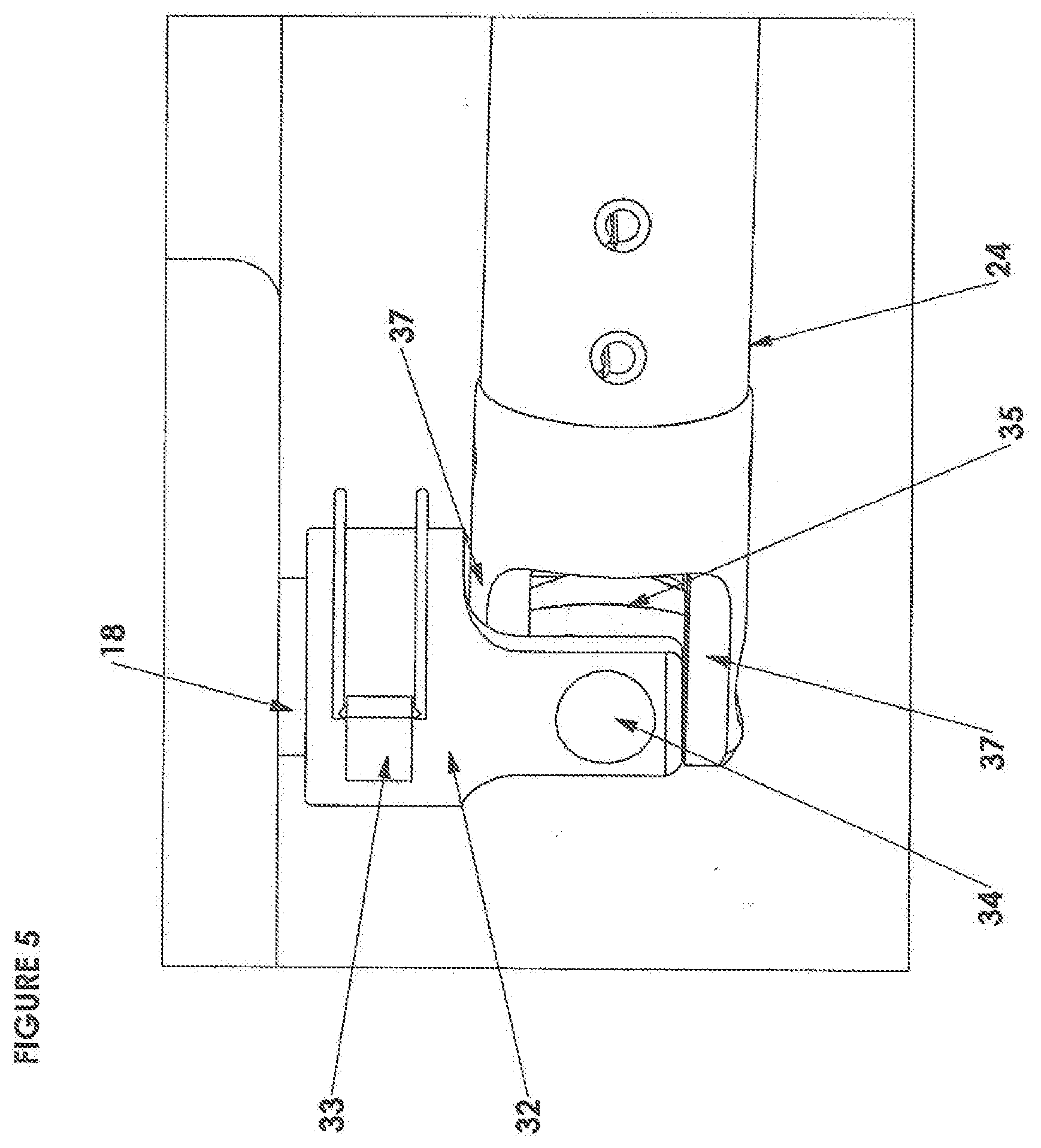
[0016] FIG. 5 is a perspective view from above of part of arms of the exercise apparatus,
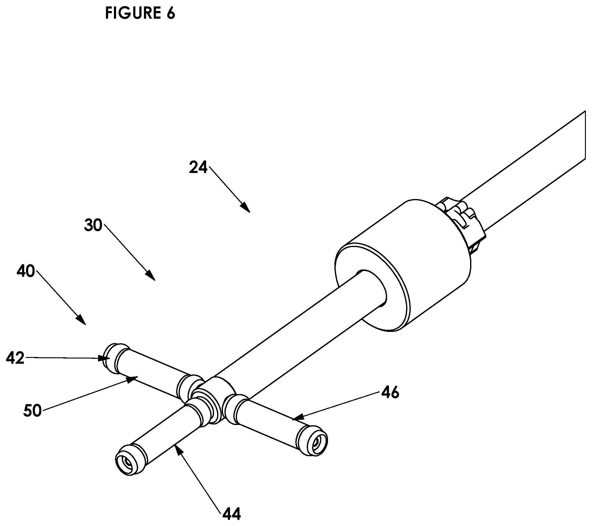
[0017] FIG. 6 is a perspective view from above of part of one of the arms of the exercise apparatus, detailing amongst other things a handle of an arm,
[0018] FIG. 7 is a plan view of upper surface of rests of the exercise apparatus,
[0019] FIG. 8 is an end view of upper surface of upper rests of the exercise apparatus,
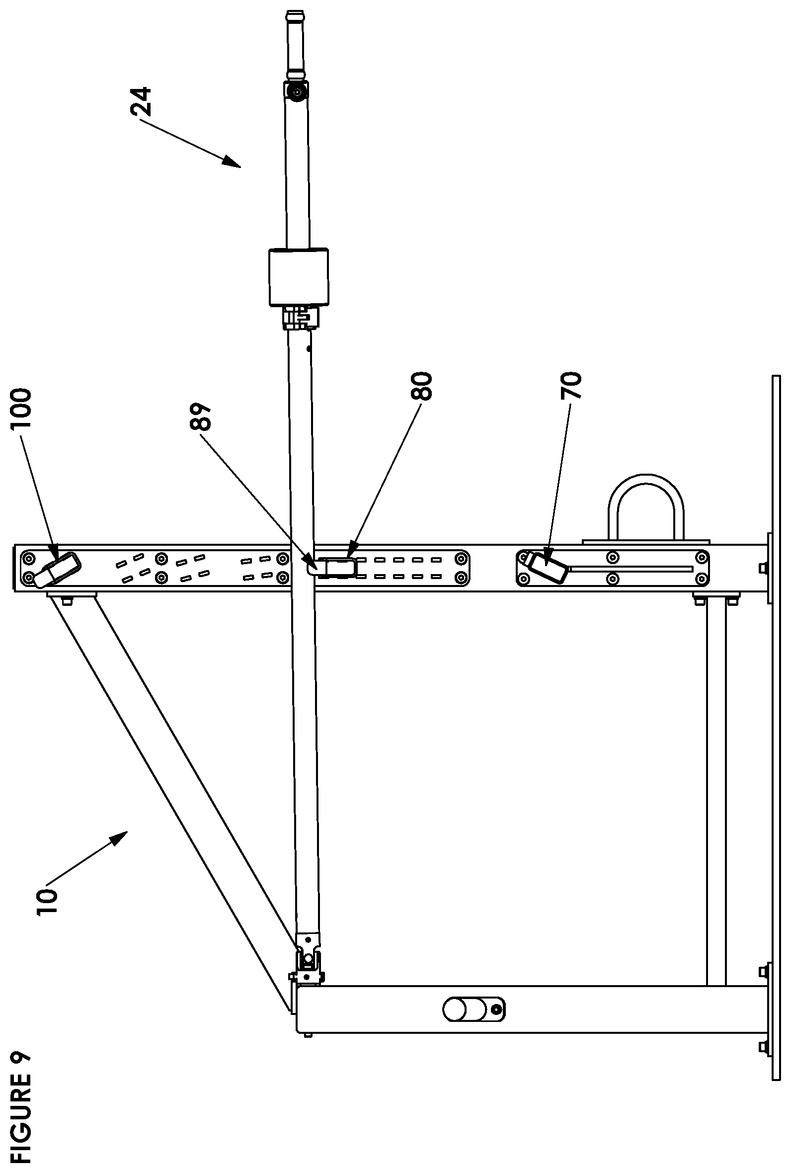
[0020] FIG. 9 is a side view of arms on the middle rests of the exercise apparatus,
[0021] FIG. 10 is a perspective view of arms on a first pair of (lower) rests,
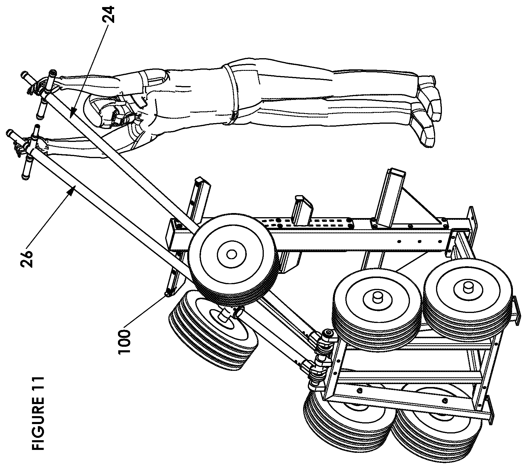
[0022] FIG. 11 is a perspective view of arms on a second pair of detachable (upper) rests,
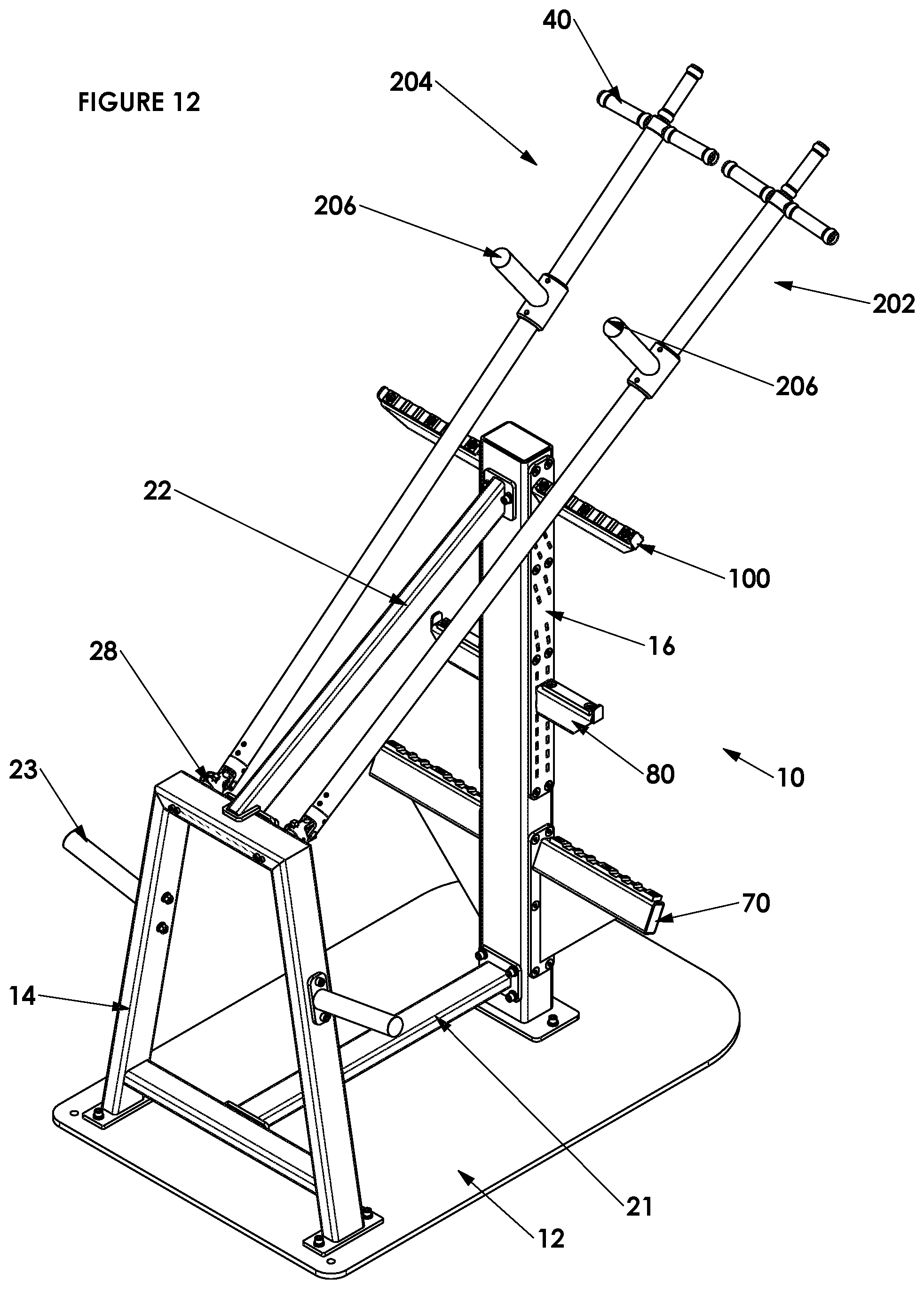
[0023] FIG. 12 is a perspective view of the exercise apparatus, utilizing a different pair of arms,
[0024] FIG. 13 is a perspective view of an alternative first upstanding support, second upstanding support, and bracing members, of another exercise apparatus,
[0025] FIG. 14 is a side view of the alternative first upstanding support, second upstanding support, and upper bracing member, of another exercise apparatus.
[0026] Referring to FIG. 1, an exercise apparatus 10 comprises a base 12, a first upstanding support 14, a second upstanding support 16, spaced from the first upstanding support. "Upstanding" support means a support designed to sit on the floor or ground and extend at least partly upwardly from the floor or ground. The term "upstanding" support does not exclude that the support can extend at least partly in another direction other than vertically, e.g. horizontally.
[0027] The first upstanding support 14 takes the form of an A frame. Referring to FIGS. 2 and 3, the first upstanding support 14 comprises a first arm supporting member 18 and a second arm supporting member 20. The arm supporting members 18, 20 conveniently take the form of tubular rods. Each arm supporting member 18, 20 has a diametric aperture through it, transverse to the longitudinal axis of the arm supporting member 18, 20. The diametric aperture is intended to align with a diametric aperture through the hollow tubular collar 32 described below.
[0028] Referring again to FIG. 1, the second upstanding support 16 takes the form of a column or post.
[0029] The exercise apparatus 10 comprises a first (lower) brace member 21 connecting the first upstanding support 14 and the second upstanding support 16. The exercise apparatus 10 comprises a second (upper) brace member 22 connecting the first upstanding support 14 and the second upstanding support 16.
[0030] The first upstanding support 14 comprises weight holders 23. The weight holders 23 are elongated rods, extending outwardly from both sides of the first upstanding support 14.
[0031] The exercise apparatus also comprises a first arm 24 and a second arm 26. The first arm 24 and the second arm 26 are substantially identical. Therefore, only the features of the first arm 24 will be described below, and it will be appreciated by the reader that the second arm 26 is the same.
[0032] The first arm 24 takes the form of an elongated member, preferably a rod or tube as shown. The rod or tube of the first arm 24 has a longitudinal axis (which need not be shown to be understood). The first arm 24 has a first end 28 and a second end 30 remote from the first end.
[0033] The first arm 24, towards its first end 28, is connected to the first arm supporting members 18 of the first upstanding support 14. Referring to FIGS. 4 and 5, which show greater detail near the first end 28 of the first arm 24, the first arm comprises a hollow tubular collar 32. The collar 32 has a diametric aperture through it, transverse to the longitudinal axis of the collar. The diametric aperture of the arm supporting member 18, 20 is aligned with a diametric aperture through the hollow tubular collar 32. Then, a D pin 33 is passed through the diametric apertures of the arm supporting member 18, 20 and the hollow tubular collar 32 to fasten them together. The collar 32 has bifurcated arms. Each arm of the collar 32 has an aperture through it. A (vertical) pin 34 is arranged through the arms of the collar 32. The (vertical) pin 34 has an enlarged portion 35. The enlarged portion 35 is rotatable about the longitudinal axis of the (vertical) pin 34. A (horizontal) pin 36 is mounted through the enlarged portion 35. The arm 24 has bifurcated mounting arms 37. Each bifurcated mounting arms 37 has an aperture through it. The (horizontal) pin 36 is mounted in the apertures of the bifurcated mounting arms 37. The arm 24 is pivotable about the longitudinal axis of the (horizontal) pin 36. The (horizontal) pin 36 enables the arm 24 to pivotably move upwardly and downwardly. The enlarged portion 35 enables the arm 24 to move in a direction away from the second upstanding support 16. It should be appreciated by the reader that the first arm 24 can be moved in a direction comprising both types of movement at the same time. Referring to FIGS. 4 and 5, the range of movement in the vertical plane is from the arm 24 touching the ground to the arm 24 being substantially vertical. Referring to FIG. 5, the range of movement in the horizontal plane is from the arm 24 being at about +90 degrees to the collar 32 to the arm 24 being at about -90 degrees to the collar.
[0034] Referring to FIG. 6, the first arm 24 has, towards its second end 30, a handle 40. The handle 40 takes the form of a multi way handle. In the embodiment of the invention shown, the handle 40 takes the form of a three way handle.
[0035] The three way handle 40 comprises a first handle part 42, a second handle part 44, and a third handle part 46. The second handle part 44 and the third handle part 46 are substantially identical to the first handle part 42. Therefore, only the features of the first handle part 42 will be described below, and it will be appreciated by the reader that the second handle part 44 and the third handle part 46 are the same.
[0036] The first handle part 42, the second handle part 44, and the third handle part 46, are all generally tubular. The tubular first handle part 42, the tubular second handle part 44, and the tubular third handle part 46 each have longitudinal axis. The longitudinal axis of the rod or tube of the first arm 24, the longitudinal axis of the first handle part 42, the longitudinal axis of the second handle part 44, and the longitudinal axis of the third handle part 46 are all arranged in approximately the same plane.
[0037] The longitudinal axis of the rod or tube of the first arm 24 is spaced from the longitudinal axis of the first handle part 42 by about 90 degrees. The longitudinal axis of the first handle part 42 is spaced from the longitudinal axis of the second handle part 44 by about 90 degrees. The longitudinal axis of the second handle part 44 is spaced from the longitudinal axis of the third handle part 46 by about 90 degrees. The longitudinal axis of the third handle part 46 is spaced from the longitudinal axis of the rod or tube of the first arm 24 by about 90 degrees.
[0038] The first handle part 42 comprises a tubular sleeve 50 that is rotatable relative to an underlying (circular cross section or effectively circular cross section) supporting part of the first handle part. The sleeve 50 of the first handle part 42 has a rough outer surface to provide an enhanced friction grip for a user.
[0039] Referring again to FIG. 1, in accordance with the invention, the first arm 24 comprises a mass 60 arranged thereon. The mass 60 is sleeve shaped. The mass 60 is slidable along the first arm 24. The first arm 24 also comprises an adjustable clamp 62 arranged thereon. In one possible embodiment, the clamp 62 has a rubber inner part. When the clamp 62 is tightened, the rubber inner part exerts a grip on the arm 24 to fix the position of the clamp along the length of the arm. The clamp 62 is permanently fixed to the mass 60 by conventional fastening means such as bolts, so the clamp and mass move as one. If the position of the mass 60 along the first arm 24 is acceptable, the clamp 62 can be tightened to temporarily fix the position of the mass at that position. If the position of the mass 60 along the first arm 24 is not acceptable, the clamp 62 can be loosened to allow the mass to be slided to a new position, at which position the clamp can be tightened to temporarily fix the position of the mass at that position. The mass 60 can be fixed at a plurality of different positions along the length of the first arm 24.
[0040] Referring to FIGS. 1 and 3, the exercise apparatus 10 comprises a first pair of rests 70. The first rest 72 of the first pair of rests 70 and the second rest 74 of the first pair of rests 70 are substantially identical, except first rest 72 is a mirror image of the second rest 74 about the second upstanding support. Therefore, only the features of the first rest 72 of the first pair of rests 70 will be described below, and it will be appreciated by the reader that the second rest 74 of the first pair of rests 70 is the same.
[0041] The first rest 72 is fixed to the second upstanding support 16, and the first rest 72 extends at least partly horizontally from the second upstanding support. The first rest 72 extends in a direction transverse to, preferably approximately perpendicular to, the longitudinal axis of the resting position of the first arm 24.
[0042] The first rest 72 has an upper surface 76 intended to bear the weight of the first arm 24. The upper surface 76 can be made from a plastic or rubber material. Referring to FIGS. 3 and 9, the upper surface 76 is inclined at an angle which corresponds to the angle of inclination of the first arm which it supports. The angle of the inclination of the upper surface matching the angle of inclination of the first arm 24 helps to reduce wear on the first arm 24 and the first rest 72.
[0043] Referring to FIGS. 1, 3 and 9, the exercise apparatus 10 comprises a first pair 80 of detachable rests. The first rest 82 of the first pair of detachable rests 80 and the second rest 84 of the first pair of detachable rests 80 are substantially identical, except first rest 82 is a mirror image of the second rest 84 about the second upstanding support. Therefore, only the features of the first rest 82 of the first pair of rests 80 will be described below, and it will be appreciated by the reader that the second rest 84 of the first pair of rests 80 is the same.
[0044] The first rest 82 is temporarily fixed to the second upstanding support 16, and the first rest 82 extends at least partly horizontally from the second upstanding support 16.
[0045] The first rest 82 has an upper surface 86 intended to bear the weight of the first arm 24. Referring to FIGS. 3 and 9, the first rest 82 is connected to the second upstanding support 16 in such a way that upper surface 86 of first rest 82 is inclined at an angle which corresponds to the angle of inclination of the first arm which it supports.
[0046] The first pair of detachable rests 80 fitted to second upstanding support 16 by lug and slot arrangement. In the embodiment shown, the second upstanding support 16 comprises slots 88 (only some of which are referenced for conciseness) and the rests 80 comprises lugs (not shown for conciseness). It should be appreciated by the reader that the angle of inclination of the slots 88 varies with height up the second upstanding support 16. It is envisaged that, in an alternative embodiment (not shown for conciseness), the second upstanding support 16 instead comprises lugs and the rests instead comprise slots, and the angle of the lugs varies with height up the second upstanding support 16. Referring to FIG. 9, it will be seen that the first rest 82 comprises a retaining protrusion 89 at the end of the arm remote from the second upstanding support 16, which assists in retaining the arm 24 on the rest. The same feature can be applied to any of the rests.
[0047] Referring to FIGS. 1, 3, 7, 8 and 9, the exercise apparatus 10 comprises a second pair 100 of detachable rests. The first rest 102 of the second pair of detachable rests 100 and the second rest 104 of the second pair of detachable rests 100 are substantially identical, except first rest 102 is a mirror image of the second rest 104 about the second upstanding support. Therefore, only the features of the first rest 102 of the first pair of rests 100 will be described below, and it will be appreciated by the reader that the second rest 104 of the second pair of detachable rests 100 is the same.
[0048] The first rest 102 is temporarily fixed to the second upstanding support 16, and the first rest 102 extends at least partly horizontally from the second upstanding support 16.
[0049] The first rest 102 has an upper surface 106 intended to bear the weight of the first arm 24. The first rest 102 is connected to the second upstanding support 16 in such a way that upper surface 106 of first rest 102 is inclined at an angle which corresponds to the angle of inclination of the first arm which it supports.
[0050] The second pair of detachable rests 100 fitted to second upstanding support 16 by lug and slot arrangement. In the embodiment shown, the second upstanding support 16 comprises slots 108 and the rests 100 comprises lugs (not shown for conciseness). The angle of inclination of the slots varies with height up the second upstanding support 16. It is envisaged that, in an alternative embodiment (not shown for conciseness), the second upstanding support 16 instead comprises lugs and the rests instead comprise slots, and the angle of the lugs varies with height up the second upstanding support 16.
[0051] Referring to FIG. 8, upper surfaces 106 of the second pair of detachable rests 100 comprises a series of cavities 110, each of the cavities being defined by successive ridges 112. The cavities 110 are designed to receive the arms 24.
[0052] Referring to FIG. 3, the second upstanding support 16 comprises a transport handle 114 to assist in manually transporting the exercise apparatus 10 into a desired position in a gymnasium.
[0053] In use, the exercise apparatus 10 is operated as follows.
[0054] The clamp can be adjusted (loosened) to allow mass to be moved, and adjusted (tightened) to temporarily fix the position of the mass at different positions along the length of the arm. If in one exercise, a user is lifting the arms at the handle, this feature enables the user to vary the effective mass being lifted.
[0055] It will be appreciated that the first arm 24 and the second arm 26 are movable independently of one another.
[0056] Example exercise names in which the arms come into engagement with the lower rests (first pair of rests 70):
[0057] Clean and press (arms are lifted from lower rest to above the upper rests, and arms are returned back to lower rests.
[0058] Deadlift.
[0059] Example exercise names in which the arms come into engagement with middle rests (first pair 80 of detachable rests):
[0060] Dips.
[0061] Horizontal laterals.
[0062] Example exercise names in which the arms come into engagement with upper rests (second pair of detachable rests 100):
[0063] Pull ups.
[0064] Hanging leg raises.
[0065] FIG. 10 shows arms 24, 26 on a first pair of (lower) rests 70.
[0066] FIG. 11 shows arms 24, 26 on a second pair of detachable (upper) rests 100.
[0067] Referring to FIG. 12, the exercise apparatus 10 comprises some parts the same as the embodiment described above for example in FIG. 1, and such parts are referenced with the same numbers. The exercise apparatus 10 of FIG. 12 comprises a different pair of arms 202, 204. Instead of the arm having a mass 60 and clamp 62, the arm 202 comprises a holder 206 for holding a mass 208. The arms 202, 204 can be quickly and easily interchanged with arms 24, 26.
[0068] Referring to FIGS. 13 and 14, in another embodiment of the invention, an exercise apparatus can comprise some parts the same as the embodiment described above for example in FIG. 1, and an alternative first upstanding support 300, second upstanding support 302, and upper bracing member 304. The first upstanding support 300 is about the same height as than the first upstanding support 14. The second upstanding support 302 is shorter than the second upstanding support 16. The first upstanding support 300 does not have holders 23 because an exercise apparatus having the first upstanding support 300, second upstanding support 302, and upper bracing member 304 would typically be used with only the arms 24, 26. An exercise apparatus having the first upstanding support 300, second upstanding support 302, and upper bracing member 304 is suitable for class based exercises because the lower profile exercise apparatus allows better eye contact between the class instructor and class participants.
[0069] An advantage of using the arms 202, 204 with weight holders 206 instead of the arms 24, 26 with sliding weights 60 is that the arms 202, 204 with weight holders 106 enable a user to use standard weights, and typically heavier weights. An advantage of using the arms 24, 26 with slider weights 60 is to provide a means of varying the effective weight of the arm by the user merely moving the weights 60, rather than needing to add or subtract weights from the apparatus 10. The sliding weight 60 can conveniently be about 10 kg. A user can vary the perceived weight they are lifting at the handle end from about 7 kg if the mass 60 is adjacent the universal joint end 28 of the arm 24 to up to about 15 kg if the mass is adjacent the handle end 30 of the arm. Given the slider weight 60 is typically lower than weight used on weight holders 206, the arm 24 with slider weights 60 allows more lifting repetitions, making the arm 24 with slider weights 60 more suitable for class based usage.
* * * * *
D00000
D00001
D00002
D00003
D00004
D00005
D00006
D00007
D00008
D00009
D00010
D00011
D00012
D00013

D00014

XML
uspto.report is an independent third-party trademark research tool that is not affiliated, endorsed, or sponsored by the United States Patent and Trademark Office (USPTO) or any other governmental organization. The information provided by uspto.report is based on publicly available data at the time of writing and is intended for informational purposes only.
While we strive to provide accurate and up-to-date information, we do not guarantee the accuracy, completeness, reliability, or suitability of the information displayed on this site. The use of this site is at your own risk. Any reliance you place on such information is therefore strictly at your own risk.
All official trademark data, including owner information, should be verified by visiting the official USPTO website at www.uspto.gov. This site is not intended to replace professional legal advice and should not be used as a substitute for consulting with a legal professional who is knowledgeable about trademark law.