Rotation Biopsy System And Handle
Peliks; Robert Bilgor ; et al.
U.S. patent application number 17/032869 was filed with the patent office on 2021-04-01 for rotation biopsy system and handle. The applicant listed for this patent is Merit Medical Systems, Inc.. Invention is credited to Robert Bilgor Peliks, Nathan Retzlaff.
| Application Number | 20210093305 17/032869 |
| Document ID | / |
| Family ID | 1000005119554 |
| Filed Date | 2021-04-01 |


| United States Patent Application | 20210093305 |
| Kind Code | A1 |
| Peliks; Robert Bilgor ; et al. | April 1, 2021 |
ROTATION BIOPSY SYSTEM AND HANDLE
Abstract
Tools used to acquire a core tissue sample are disclosed. A portion of the tools may be configured to rotate when acquiring the core tissue sample. The tools include a partoff tab to sever the core tissue sample from a lesion and to retain the core tissue sample when the tool is removed from the patient. The tools may further include a light source to illuminate a working field.
| Inventors: | Peliks; Robert Bilgor; (San Francisco, CA) ; Retzlaff; Nathan; (Kenosha, WI) | ||||||||||
| Applicant: |
|
||||||||||
|---|---|---|---|---|---|---|---|---|---|---|---|
| Family ID: | 1000005119554 | ||||||||||
| Appl. No.: | 17/032869 | ||||||||||
| Filed: | September 25, 2020 |
Related U.S. Patent Documents
| Application Number | Filing Date | Patent Number | ||
|---|---|---|---|---|
| 62907135 | Sep 27, 2019 | |||
| Current U.S. Class: | 1/1 |
| Current CPC Class: | A61B 17/3421 20130101; A61B 10/0275 20130101; A61B 2017/3409 20130101; A61B 90/30 20160201 |
| International Class: | A61B 10/02 20060101 A61B010/02; A61B 17/34 20060101 A61B017/34; A61B 90/30 20060101 A61B090/30 |
Claims
1. A tool for acquiring a tissue sample, comprising: a handle; a cannula assembly; a trocar assembly; a rotation member configured to rotate the cannula assembly in a first direction and the trocar assembly in the first direction and a second direction; and a partoff tab actuation member.
2. The tool of claim 1, wherein the cannula assembly comprises: an outer cannula; an inner cannula coaxially disposed within the outer cannula, wherein a portion of the outer cannula is axially slidable relative to the inner cannula; and a partoff tab coupled to the outer cannula.
3. The tool of claim 2, wherein the outer and inner cannulas are configured to rotate together in the first direction.
4. The tool of claim 2, wherein the inner cannula comprises a helical member disposed on an internal surface configured to longitudinally displace a tissue sample when the inner cannula is rotating.
5. The tool of claim 2, wherein the partoff tab is configured to retain a tissue sample within the inner cannula when the partoff tab is in the actuated state.
6. The tool of claim 2, wherein the partoff tab is configured to sever a tissue sample from a lesion when in the actuated state and the cannula assembly is rotated.
7. The tool of claim 1, wherein the trocar assembly comprises: a trocar comprising a sharp distal end and slidingly disposed within the cannula assembly; an externally threaded member; and an internally threaded nut fixedly coupled to the trocar and operatively coupled to the externally threaded member.
8. The tool of claim 7, wherein the internally threaded nut is configured to proximally displace the trocar when the externally threaded portion is rotated in the first direction and to distally displace the trocar when the externally threaded portion is rotated in the second direction.
9. The tool of claim 1, wherein the rotation member comprises: a first motor; a rotation drive member coupled to the first motor, the cannula assembly, and the trocar assembly; and a power source.
10. The tool of claim 1, wherein the partoff tab actuation member comprises: a second motor; a partoff tab actuator coupled to the second motor, wherein the partoff tab actuator comprises a neutral state, a partoff tab actuation state, and an anti-rotation state; and a power source.
11. The tool of claim 1, further comprising a coaxial introducer assembly removably disposed over a distal portion of the cannula assembly.
12. The tool of claim 1, further comprising a light source.
13. A rotation biopsy tool, comprising a disposable member and a reusable member removably disposed within the disposable member.
14. The tool of claim 13, wherein the disposable member comprises: an outer housing; a cannula assembly; a trocar assembly; an activation button configured to activate rotation of a first motor in a first direction; and an ejection button configured to activate rotation of the first motor in a second direction.
15. The tool of claim 13, wherein the reusable member comprises: an inner housing; a rotation member comprising: a first motor; and a rotation drive member; a partoff tab actuation member, comprising: a second motor; and a partoff tab actuator; a light source; and a power source.
16. A method of obtaining a core tissue sample, comprising: obtaining a core tissue sampling tool comprising a cannula assembly and a trocar assembly; inserting a distal portion of the cannula assembly and the trocar assembly into an insertion site; positioning the distal portion of the cannula assembly and the trocar assembly adjacent a lesion; activating rotation of the cannula assembly and a portion of the trocar assembly in a first direction; advancing the distal portion of the cannula assembly into the lesion, wherein the core tissue sample is disposed within the distal portion of the cannula assembly; activating a partoff tab while the cannula assembly is rotating, wherein the core tissue sample is severed from the lesion by the partoff tab; removing the distal portion of the cannula assembly from the insertion site; and ejecting the tissue sample from the core tissue sample cannula assembly.
17. The method of claim 16, wherein a trocar is displaced proximally when the trocar assembly is rotated in a first direction.
18. The method of claim 16, further comprising activating a portion of the trocar assembly to rotate in a second direction, wherein a trocar of the trocar assembly is displaced distally to eject the core tissue sample from the cannula assembly.
19. The method of claim 16, further comprising illuminating the insertion site with a light source coupled to the core tissue sampling tool.
20. The method of claim 16, further comprising retaining the core tissue sample within the cannula assembly with the activated partoff tab when the distal portion of the cannula assembly is removed from the insertion site.
Description
RELATED APPLICATIONS
[0001] This application claims priority to U.S. Provisional Application No. 62/907,135, filed on Sep. 27, 2019 and titled "Rotation Biopsy System and Handle" which is hereby incorporated by reference in its entirety.
TECHNICAL FIELD
[0002] The present disclosure relates generally to devices used to acquire a tissue sample, particularly in medical devices. More specifically, the present disclosure relates to core tissue sampling tools.
BRIEF DESCRIPTION OF THE DRAWINGS
[0003] The embodiments disclosed herein will become more fully apparent from the following description and appended claims, taken in conjunction with the accompanying drawings. These drawings depict only typical embodiments, which will be described with additional specificity and detail through use of the accompanying drawings in which:
[0004] FIG. 1 is a perspective view of a core tissue sampling tool.
[0005] FIG. 2 is a partial cross-sectional side view of the core tissue sampling tool of FIG. 1.
[0006] FIG. 3A is a top view of a distal portion of a cannula assembly of the core tissue sampling tool of FIG. 1.
[0007] FIG. 3B is a bottom view of a distal portion of the cannula assembly of the core tissue sampling tool of FIG. 1.
[0008] FIG. 3C is a cross-sectional side view of a distal portion of the cannula assembly of the core tissue sampling tool of FIG. 1 with a partoff tab in an actuated state.
[0009] FIG. 4A is a partial cross-sectional side view of the core tissue sampling tool of FIG. 1 in an insertion state.
[0010] FIG. 4B is a cross-sectional side view of a distal portion of the core tissue sampling tool of FIG. 1 in the insertion state.
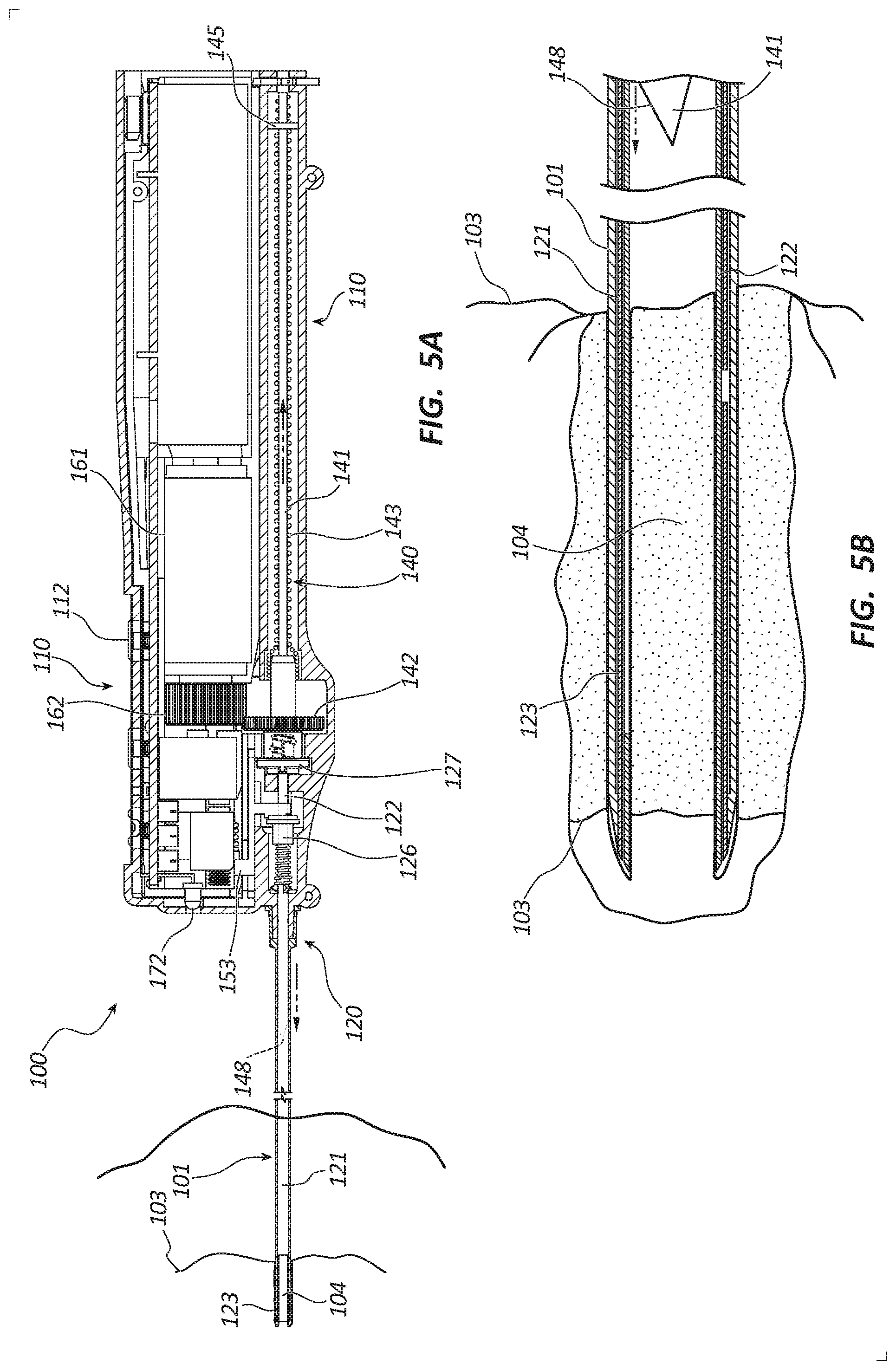
[0011] FIG. 5A is a partial cross-sectional side view of the core tissue sampling tool of FIG. 1 in a tissue sampling state.
[0012] FIG. 5B is a cross-sectional side view of a distal portion of the core tissue sampling tool of FIG. 1 in the tissue sampling state.
[0013] FIG. 6A is a partial cross-sectional side view of the core tissue sampling tool of FIG. 1 in a partoff tab actuation state.
[0014] FIG. 6B is a cross-sectional side view of a distal portion of the core tissue sampling tool of FIG. 1 in the partoff tab actuation state.
[0015] FIG. 7A is a partial cross-sectional side view of the core tissue sampling tool of FIG. 1 in a tissue ejection state.
[0016] FIG. 7B is a cross-sectional side view of a distal portion of the core tissue sampling tool of FIG. 1 in the tissue ejection state.
[0017] FIG. 8A is a perspective view of a disposable member of another core tissue sampling tool.
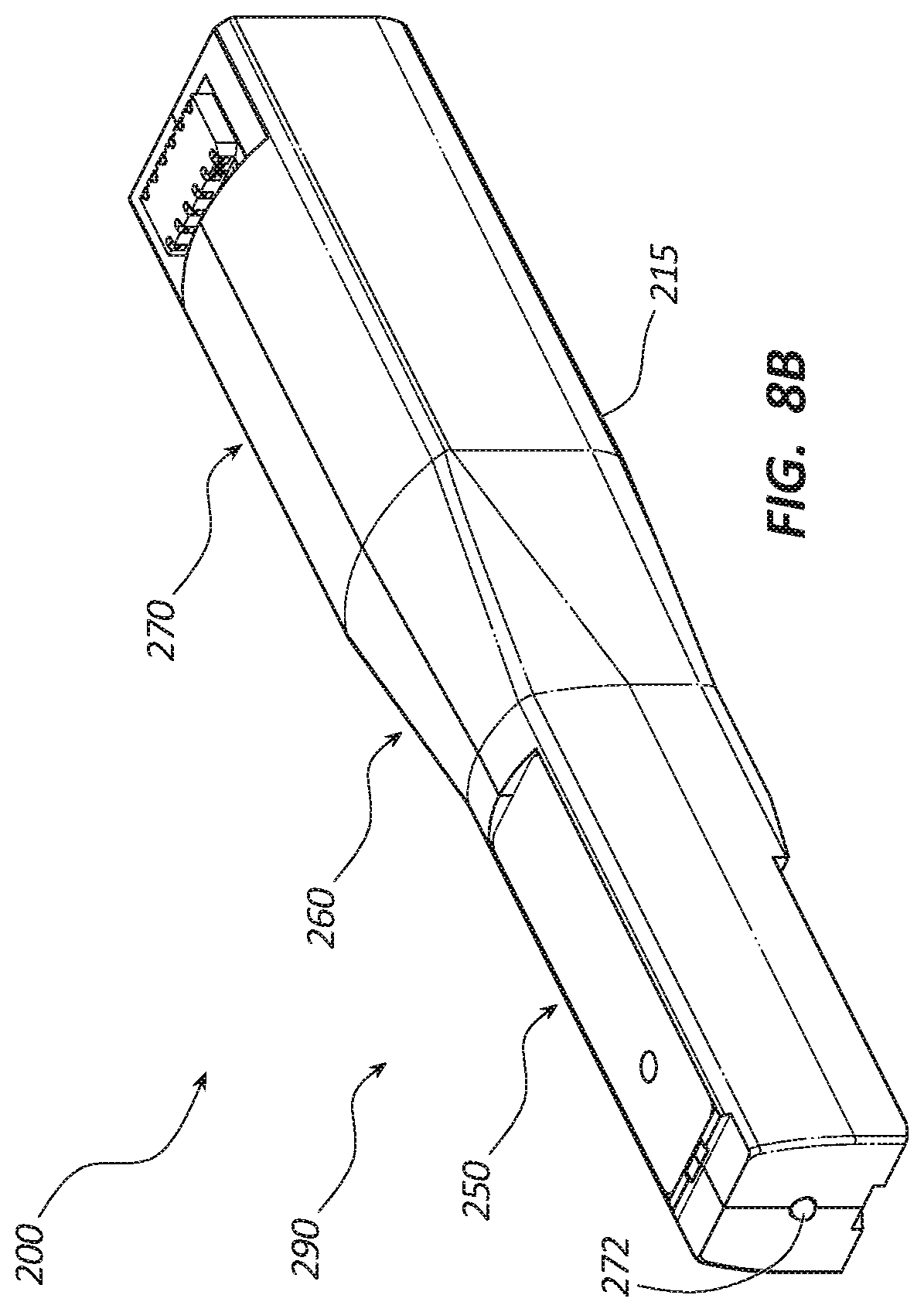
[0018] FIG. 8B is a perspective view of a reusable member of the core tissue sampling tool of FIG. 8A.
DETAILED DESCRIPTION
[0019] A core tissue sampling tool may include a handle, a trocar, a cannula assembly, a rotation drive member configured to rotate the cannula assembly and/or to longitudinally displace the trocar, and a drive member configured to actuate a partoff tab. The partoff tab may be configured to sever a portion of a tissue sample disposed within the cannula assembly from a location within a patient's body, such as from a lesion. The rotation drive member may also be configured to displace the trocar to eject the tissue sample from the cannula assembly. In some embodiments, the core tissue sampling tool may include a light source. Alternatively, or additionally, in some embodiments, the handle may include a disposable portion and a reusable portion.
[0020] The core tissue sampling tool may be used by a practitioner to acquire a core tissue sample from within the body of the patient, for example a tissue sample from a lesion with the body of the patient. In some procedures, the trocar and the cannula assemblies may be inserted into the body of the patient under ultrasound guidance to a location adjacent a target lesion. A light source may be used to illuminate the insertion site. The rotation drive member may be activated to displace the trocar proximally and to rotate the cannula assembly. As the cannula assembly is rotating it can be advanced into the lesion to sever the longitudinal portion of the tissue sample. Thus, as the cannula assembly is advanced, a tissue sample, such as a core tissue sample, may be severed along its longitudinal length and disposed within the cannula assembly. The partoff tab may be actuated while the cannula assembly is rotating, severing a distal portion of the core tissue sample from the lesion. The cannula assembly may then be withdrawn from the patient's body and the core tissue sample ejected from the cannula assembly. In other instances, the cannula assembly may be repositioned for acquisition of subsequent core tissue samples prior to withdrawal of the cannula assembly from the patient's body.
[0021] Embodiments may be understood by reference to the drawings, wherein like parts are designated by like numerals throughout. It will be readily understood by one of ordinary skill in the art having the benefit of this disclosure that the components of the embodiments, as generally described and illustrated in the figures herein, could be arranged and designed in a wide variety of different configurations. Thus, the following more detailed description of various embodiments, as represented in the figures, is not intended to limit the scope of the disclosure, but is merely representative of various embodiments. While the various aspects of the embodiments are presented in drawings, the drawings are not necessarily drawn to scale unless specifically indicated.
[0022] Various features are sometimes grouped together in a single embodiment, figure, or description thereof for the purpose of streamlining the disclosure. Many of these features may be used alone and/or in combination with one another.
[0023] The phrases "coupled to" and "in communication with" refer to any form of interaction between two or more entities, including mechanical, electrical, magnetic, electromagnetic, fluid, and thermal interaction. Two components may be coupled to or in communication with each other even though they are not in direct contact with each other. For example, two components may be coupled to or in communication with each other through an intermediate component.
[0024] The directional terms "distal" and "proximal" are given their ordinary meaning in the art. That is, the distal end of a medical device means the end of the device furthest from the practitioner during use. The proximal end refers to the opposite end, or the end nearest the practitioner during use. As specifically applied to the cannula assembly portion of a core tissue sampling tool, the proximal end of the cannula assembly refers to the end nearest the handle and the distal end refers to the opposite end, the end nearest the tissue sampling end.
[0025] "Fluid" is used in its broadest sense, to refer to any fluid, including both liquids and gases as well as solutions, compounds, suspensions, etc., which generally behave as fluids. "Tissue" is also used in its broadest sense, to refer to any type of tissue, including muscle, epithelial, connective, nervous, etc., which is in the human body.
[0026] FIGS. 1-8B illustrate different views of several core tissue sampling tools and related components. In certain views each device may be coupled to, or shown with, additional components not included in every view. Further, in some views only selected components are illustrated, to provide detail into the relationship of the components. Some components may be shown in multiple views, but not discussed in connection with every view. Disclosure provided in connection with any figure is relevant and applicable to disclosure provided in connection with any other figure or embodiment.
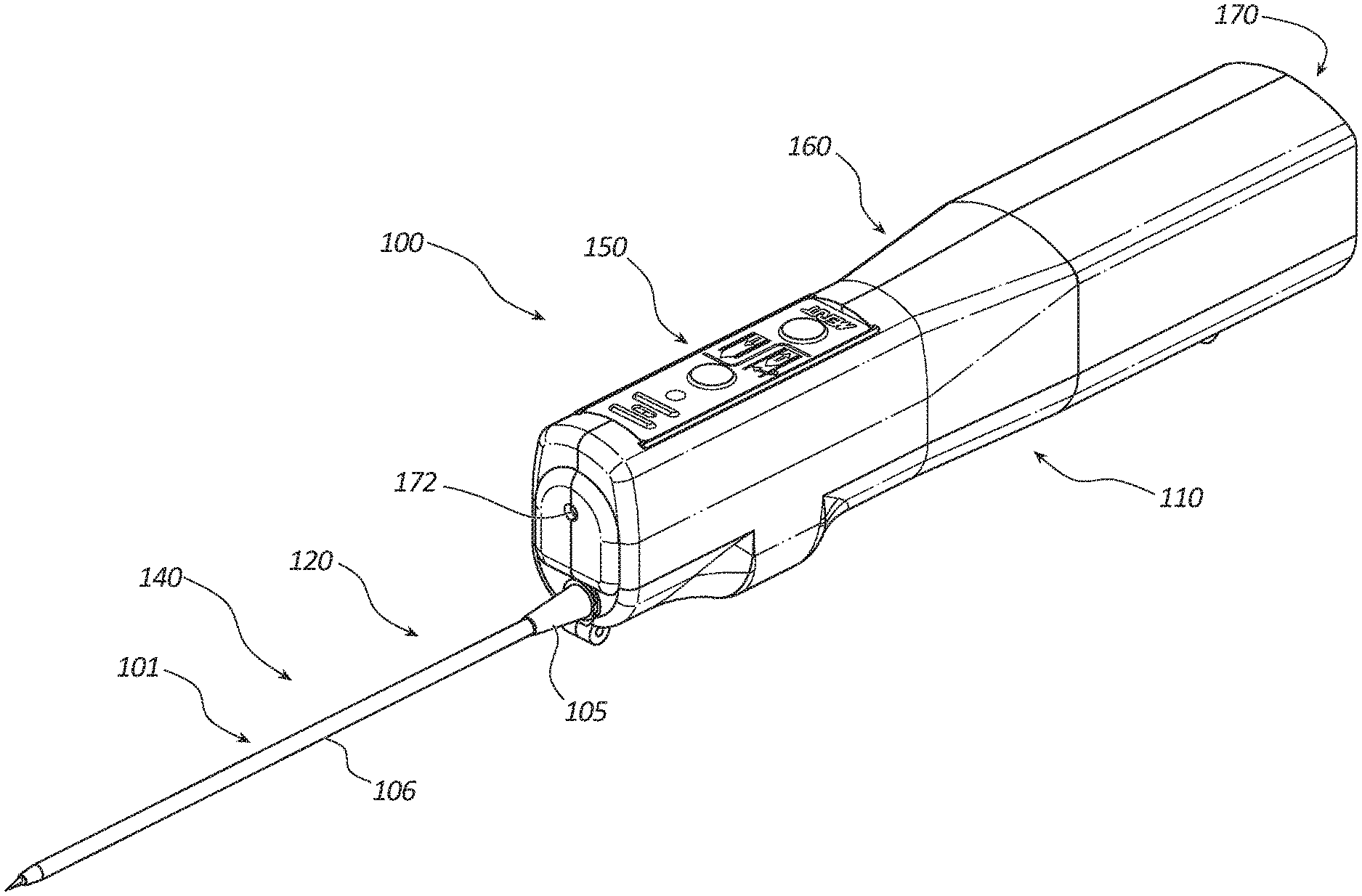
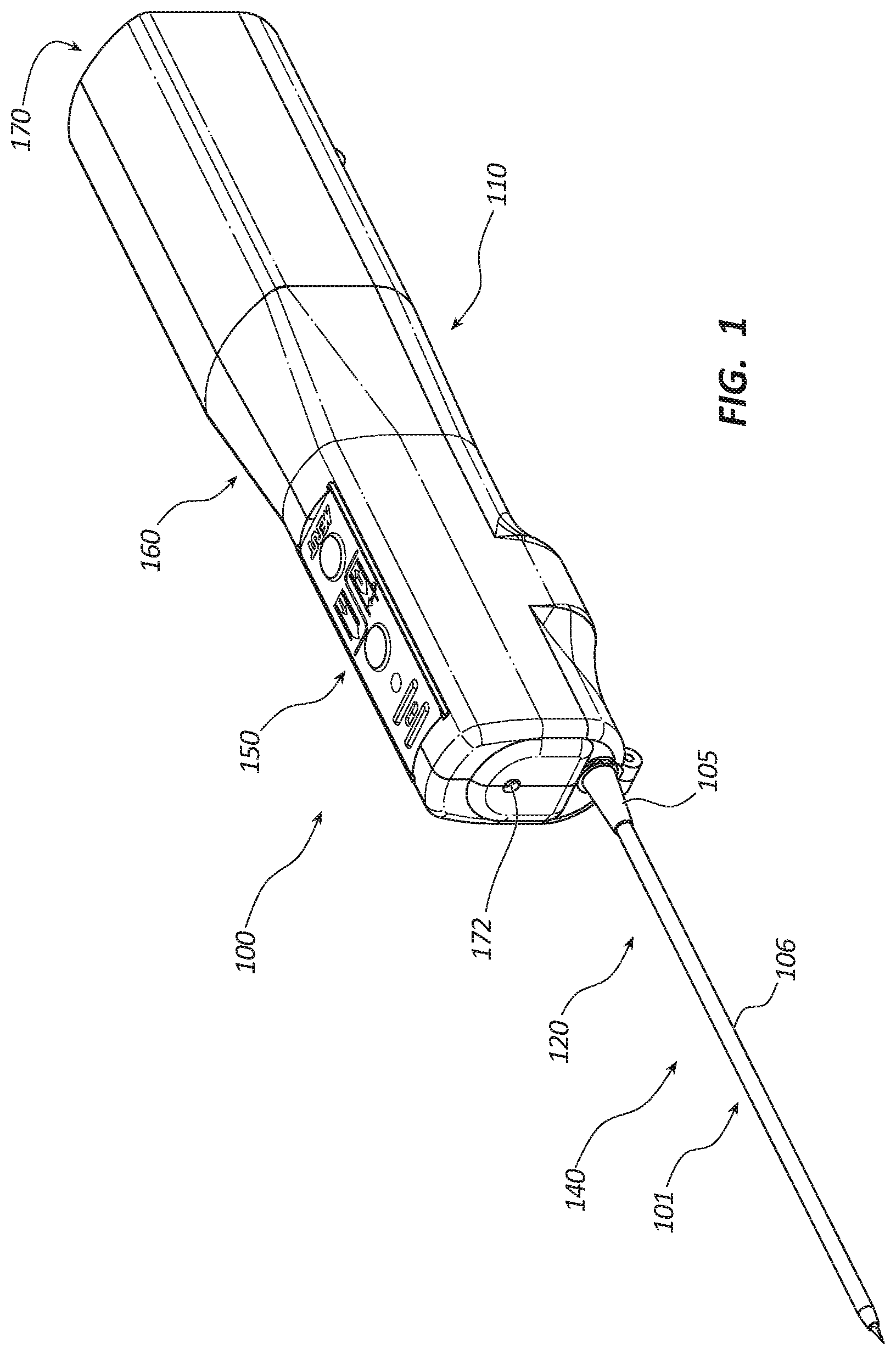
[0027] FIG. 1 depicts a perspective view of an embodiment of a core tissue sampling tool 100. The sampling tool 100 may comprise a handle 110, coaxial introducer 101, cannula assembly 120, trocar assembly 140, power source 170, rotation member 160, partoff tab actuating member 150, and light source 172. The coaxial introducer 101 may include a connector 105 and a sheath 106. The coaxial introducer 101 may be disposed over distal portions of the cannula assembly 120 and trocar assembly 140. In certain embodiments, the sheath 106 may be coated with a lubricious coating, such as a hydrophilic coating, to reduce an insertion force of the sheath 106 resulting in higher quality tissue samples. The coaxial introducer 101 may be releasably coupled to the handle 110. In some embodiments, the coaxial introducer 101 may be coupled to the handle by a locking button that is configured to releasably engage with the connector 105. The locking button may include a transparent portion aligned with the light source 172 to passage of light from the light source 172 through the locking button.
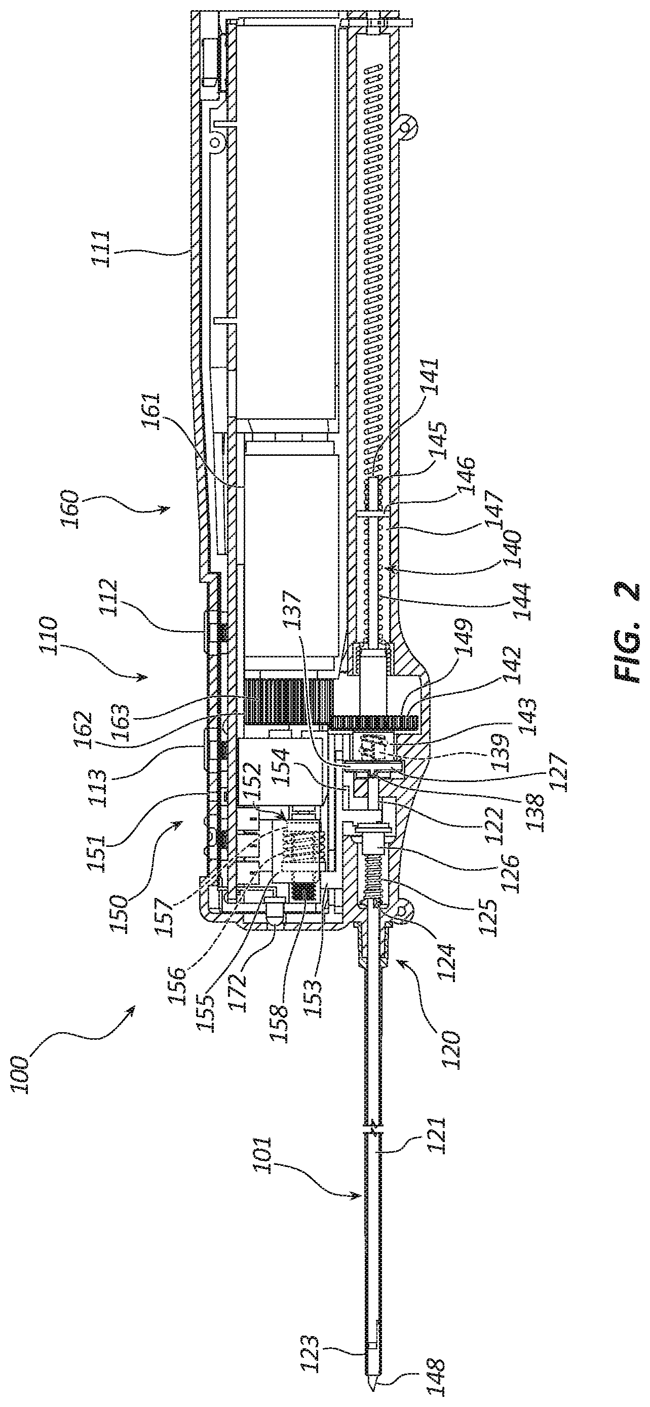
[0028] FIG. 2 is a cross-sectional view of the core tissue sampling tool 100. As illustrated, the rotation member 160 includes a first motor 161 and a rotation drive member 162 fixedly coupled to the first motor 161. The first motor 161 may comprise, for example, a brushed or brushless direct current (DC) motor, a piezo motor, hydraulic or pneumatic actuator, solenoid, shape memory or muscle-wire, etc. The first motor 161 may be coupled to the power source (170 of FIG. 1) such that energy from the power source (170 of FIG. 1) may be used to cause the first motor 161 to rotate in a clockwise or counter-clockwise direction. Activation of the rotation of the first motor 161 may be caused by manipulation of a button or other actuator. In some embodiments, two or more actuators may be configured to activate the first motor 161. For example, in some embodiments, depression of either 1) a first button such as coring button 112 or 2) a second button such as ejection button 113 may be configured to activate the first motor 161. As illustrated, the rotation drive member 162 may include a circular gear having teeth 163. In other embodiments, the rotation drive member 162 may include any other suitable rotatable drive mechanism. For example, the rotation drive member 162 may include a pulley and belt, wheel, harmonic drive, hollow-shaft motor, gear box, etc.
[0029] In embodiments with a hollow-shaft motor, the cannula assembly 120 and trocar assembly 140 may be configured to slide within the hollow-shaft of the motor. In such embodiments, the rotation bushing 142 may be keyed to engage with the rotation driver member 162. Furthermore, in certain embodiments, the rotation bushing 142 may comprise magnets. In such embodiments, the magnets may be configured to engage with the rotation drive member 162. Furthermore, in embodiments wherein the motor comprises wire and magnets (such as a DC motor) the motor magnets may be coupled to rotation drive member 162 and the wire coils disposed at the location shown by motor 161 (though in such embodiments the motor may be understood as a combination of the magnets and coils).
[0030] The first motor 161 may be configured to rotate the rotation drive member 162 in both the clockwise and counter-clockwise directions. The rotation drive member 162 may be configured to operatively couple with the cannula assembly 120 and the trocar assembly 140 to facilitate their rotation in a first and a second direction relative to the clockwise and counter-clockwise rotation of the first motor. For example, in the depicted embodiment, the rotation drive member 162 is a circular gear which rotates in the same direction as the first motor 161. In another embodiment, the motor may include a gearhead configured to engage with the rotation drive member 162 and to rotate the rotation drive member 162 in a direction opposite of the first motor 161. A gear ratio of the gearhead may be about 5.3:1. Other suitable gear ratios are within the scope of this disclosure. The teeth 163 of rotation drive member 162 meshes with teeth 149 of a rotation bushing 142 of a trocar assembly 140. This results in rotation of the trocar assembly 140 in an opposite direction from the rotation direction of the first motor 161. In other words, if the first motor 161 rotates in a clockwise direction, the trocar assembly 140 will rotate in a counter-clockwise direction. In other embodiments, the first motor 161 and the trocar assembly 140 may rotate in the same direction. For convenience, rotation direction of the trocar assembly 140 and a cannula assembly 120 are described as either a first direction or a second direction with an understanding that the rotation directions may be opposite or the same as the rotation direction of the first motor 161.
[0031] The partoff tab actuating member 150 is shown in FIG. 2, and, in the illustrated embodiment, comprises a second motor 151, an actuator drive nut 152, and an actuator 153. The second motor 151 may comprise, for example, a brushed or brushless DC motor, a piezo motor, hydraulic or pneumatic actuator, solenoid, shape memory or muscle-wire, etc. The second motor 151 may be coupled to the power source (170 of FIG. 1) such that the power source (170 of FIG. 1) is configured to provide energy to cause the second motor 151 to rotate in the clockwise and the counter-clockwise directions. The actuator drive nut 152 may be coupled to the second motor 151 such that the actuator drive nut 152 is linearly displaced proximally or distally as the second motor 151 rotates.
[0032] The actuator drive nut 152 may be comprised of a carriage 155, a bushing 157 and a compliant member 156 (e.g., compression spring). The carriage 155 includes a threaded hole that engages with a leadscrew 158 coupled to the second motor 151. The carriage 155 may include flags (not shown) that are configured to engage with a limit switch (not shown). The limit switch may of any suitable type. For example, the limit switch may be a photointerrupter, magnetic reed, mechanical limit, etc. The compliant member 156 and bushing 157 may be configured to apply constant force to the actuator 153. For example, if the carriage 155 moves to a full distal position, then it might apply too much force on the actuator 153 and/or stall the second motor 151. In the illustrated embodiment, the actuator 153 contacts the bushing so that a force applied to the actuator 153 by the actuator drive nut 152 is limited by a force from the compliant member 156, causing the second motor to be less likely to stall. The actuator drive nut 152 may be selectively coupled to the actuator 153. The actuator drive nut 152 may distally displace the actuator 153 to actuate a portion of the cannula assembly 120 in an actuating state, decouple from the actuator 153 in a neutral state, and proximally displace the actuator 153 in an anti-rotation state. The actuator 153 may further comprise an anti-rotation feature 154 distending, for example, from a proximal portion. The anti-rotation feature 154 may be configured to engage with a portion of the cannula assembly 120 to prevent rotation of the cannula assembly 120 in the second direction. In another embodiment, the partoff tab actuating member 150 may not comprise the second motor 151. In this embodiment the partoff tab actuating member may include a spring-loaded mechanism activated by a depressible button.
[0033] As depicted in FIG. 2, the cannula assembly 120 may include an outer cannula 121, an inner cannula 122, a partoff tab 123, a limiting tab 124, a resilient member 125, an actuation bushing 126, and a decoupling bushing 127. The inner cannula 122 is shown to be coaxially disposed within the outer cannula 121. Distal portions of the cannulas 121, 122 extend from the handle 110 while proximal portions are disposed within the handle 110. A collective distal end of the cannulas 121, 122 may be circumferentially sharpened to provide a circular cutting edge. In other embodiments, the collective distal ends of the cannulas may be sharpened by swaging, lubrication, drawing, etc. The cannulas 121, 122 may be formed of a variety of materials, including, for example, stainless steel, nitinol, titanium, etc. In some embodiments, the inner cannula 122 may include a helical protrusion extending into a lumen. The helical protrusion may be configured to facilitate tissue sampling when the inner cannula is rotated. In certain embodiments, the outer cannula 121 may be coated with a lubricious coating, such as a hydrophilic coating, to reduce an insertion force of the outer cannula 121 resulting in higher quality tissue samples.
[0034] FIGS. 3A-3B depict a distal portion of the cannula assembly 120 with the partoff tab 123 in a non-actuated state; FIG. 3A is a top view of the distal portion of the cannula assembly 120 and FIG. 3B is a bottom view of the distal portion of the cannula assembly. As shown in FIGS. 3A-3B, the partoff tab 123 is disposed adjacent a distal end of the cannula assembly 120. In the illustrated embodiment, the partoff tab 123 is coupled to a middle portion 136 and a distal portion 135 of the outer cannula 121 and disposed over an aperture 130 of the inner cannula 122. As shown in the embodiment of the figures, the outer cannula 121 is also fixedly coupled to the inner cannula 122 at a location distal to the partoff tab 123. These elements may be coupled in a variety of ways, for example, the outer cannula 121 and the inner cannula 122 may be coupled by welding, gluing, swaging, etc. Additionally, in the illustrated embodiment, a tab 131 of the distal portion 135 disposed opposite of the partoff tab 123 and extends proximally into a tab receiver 132 of the middle portion 136. A tab gap 133 is defined by the tab 131 and the tab receiver 132. A gap 134 is defined between the distal portion 135 and the middle portion 136 when the partoff tab 123 is in the non-actuated state, as shown in FIGS. 3A-3B.
[0035] FIG. 3C is a cross-sectional side view the partoff tab 123, shown in an actuated state (as compared to the non-actuated state of FIGS. 3A-3B). As shown in the figures, in the illustrated embodiment, the actuated state may be achieved when the outer cannula 121 is distally displaced relative to the inner cannula 122. This distal displacement may be caused by distal displacement of the actuator 153 by the actuator drive nut 152. The distal displacement of the outer cannula 121 can close the tab gap 133 and the gap 134. In another embodiment, a length of the gap 134 may be longer than a length of the tab gap 133. In this embodiment, the tab cap 133 may be closed while the gap 134 remains open to prevent capture of tissue in the gap 134. Closing of the gaps 133, 134 may displace a proximal end of the partoff tab 123 towards a distal end and effectively shortens the longitudinal length along an axis of the cannula assembly 120 between proximal and distal ends of the partoff tab 123. The partoff tab 123 may be configured to be deflected radially inward through the aperture 130 into the lumen of the inner cannula 122 when the gaps 133, 134 are closed or otherwise moved together. In some embodiments, the partoff tab 123 may be pre-biased inwardly in the non-actuated state to facilitate inward radial deflection. The partoff tab 123 may be deflected from about 50% to about 90%, from about 60% to about 80%, or from about 70% to about 80% of an internal diameter of the inner cannula 122. The partoff tab 123 (in the actuated state) can be configured to sever a distal portion of a tissue sample disposed within the inner cannula 122 from the body and to retain the tissue sample within the inner cannula 122 when the cannula assembly 120 is withdrawn from a patient's body. In some embodiments, the partoff tab 123 may be annealed or treated otherwise to increase the strength of the partoff tab 123 such that the partoff tab 123 may withstand multiple actuations.
[0036] Referring again to FIG. 2, a proximal end of the outer cannula 121 may be fixedly coupled to an actuation bushing 126, for example, by gluing, welding, overmolding, stamping, laser cutting, etc. The outer cannula 121 may include a limiting tab 124 disposed distally of the actuation bushing 126. In some embodiments, the limiting tab 124 may be formed by cutting the wall of the outer cannula 121 to define at least one longitudinal limiting tab 124 and deforming the cut portion such that the limiting tab 124 extends radially outward from the outer cannula 121 wall. For example, the outer cannula 121 may be longitudinally compressed relative to the inner cannula 122 such that the limiting tab 124 is deflected radially outward. The limiting tab 121 may be welded to the inner cannula 122 such that the inner cannula 122 and the outer cannula rotationally locked together. A resilient member 125 (such as, for example, a spring) may be disposed between the actuation bushing 126 and the limiting tab 124. In the illustrated embodiment, when the partoff tab 123 is actuated, the actuator 153 engages with the actuation bushing 126 and displaces the actuation bushing 126 and a portion of the outer cannula 121 distally relative to the inner cannula 122 such that the gaps 133, 134 are at least partially closed and the resilient member 125 is compressed between the limiting tab 124 and the actuation bushing 126. When the partoff tab 123 is returned to the non-actuated state, the actuator 153 disengages from the actuation bushing 126 and the resilient member 125 displaces the actuation bushing 126 and the portion of the outer cannula 121 proximally, opening the gaps 133, 134 and returning the partoff tab 123 to the non-actuated state.
[0037] As illustrated in FIG. 2, a proximal end of the inner cannula 122 is fixedly coupled to a decoupling bushing 127. The decoupling bushing 127 may include a circular flange 137 having a nub 138 extending distally from a distal face of the flange 137. The nub 138 can engage with the anti-rotation feature 154 of the actuator 153 to restrict rotation of the decoupling bushing 127 in the second direction when the actuator 153 is displaced proximally. In other words, the decoupling bushing 127 may be free to rotate in both the first and second directions until the actuator 153 is displaced proximally, such as when a core tissue sample is ejected from the sample tool, as will be explained below. In another embodiment, the core tissue sampling tool 100 may include a split washer ratchet that allows the decoupling busing to rotate in only one direction. An external threaded portion 139 may extend proximally from the flange 137. The threaded portion 139 may be configured to threadingly couple to, and decouple from, a rotation bushing 142 of the trocar assembly 140. When coupled, the rotation bushing 142 may be coupled to the rotation drive member 162 such that the rotation bushing 142, the cannula assembly 120, and a portion of the trocar assembly 140 can be rotated in the first direction. Rotation of the rotation bushing 142 in the second direction by the rotation drive member 162 decouples the decoupling bushing 127 from the rotation bushing 142 because the decoupling bushing 127 is prevented from rotating in the second direction by the anti-rotation feature 154. In another embodiment, when the actuator is in a distal position, the rotation drive member 162 may be rotated in the second direction by the first motor 161 to decouple the rotation drive member 162 from the bushing 127. When decoupled, the decoupling bushing 127 and the cannula assembly 120 are not rotated in the second direction while the portion of the trocar assembly 140 is rotated in the second direction.
[0038] In some embodiments, the trocar assembly 140 may include the trocar 141, the rotation bushing 142, an externally threaded member 144, and a nut 145. As depicted in FIG. 2, the rotation bushing 142 may be configured as a circular gear having a plurality of teeth 149. The teeth 149 may be configured to mesh with the teeth 163 of the rotation drive member 162. In other embodiments, the rotation bushing 142 may be configured as a bearing, a pulley wheel, etc., or any other rotation driving mechanism. The rotation bushing 142 may include an internally threaded portion 143 configured to threadingly couple with and decouple from the decoupling bushing 127 as described above. In other embodiments, the internally threaded portion 143 may extend from the externally threaded member 144.
[0039] As shown in FIG. 2, in the illustrated embodiment, the trocar 141 is coaxially disposed within the inner cannula 122. The trocar 141 is configured to be proximally and distally translated within the inner cannula 122. The trocar 141 may be a rod formed from a variety of materials, including rigid materials, for example, including, stainless steel, titanium, nitinol, rigid plastics, etc. In some embodiments, the trocar 141 may be a tube having a lumen. The trocar 141 can comprise a sharp distal end 148 configured to penetrate tissue. The distal end 148 may include a plurality of facets and a sharp point. In other embodiments, the distal end 148 may include a bevel, a pencil point, or other tissue penetrating geometries or configurations. In other embodiments, the trocar 141 may be blunt. In another embodiment, the sharp trocar 141 may be replaced with a blunt trocar prior to ejection of a tissue sample from the cannula assembly 120.
[0040] The externally threaded member 144 may be fixedly coupled to and extend proximally from the rotation bushing 142 to adjacent a proximal end of the housing 111. For example, a distal portion of the threaded member 144 can be disposed over a proximal portion of the rotation bushing 142 as depicted in FIG. 2. In another embodiment, the distal portion of the threaded member 144 may be disposed within the proximal portion of the rotation bushing 142. Embodiments wherein the threaded member 144 is press fit into the rotation bushing 142 are within the scope of this disclosure. The threaded member 144 may be disposed around a portion of the trocar 141. As shown in FIG. 2, the threaded member 144 may comprises an elongate coil configured to longitudinally translate the nut 145 when rotated. In some embodiments, the nut 145 may be longitudinally translated by pulse wave modulation, magnetic force, compressed gas, etc. The threaded member 144 may be formed of a wire or rod made of a rigid material. For example, the wire or rod may be formed from stainless steel, titanium, polymers such as polycarbonate, etc. The pitch of the coils may be determined by the number of rotations of the threaded member 144 desired to translate the nut 145 from a proximal end to a distal end of the threaded member 144. The coil pitch may range from about 0.01 inch to about 0.20 inch, from about 0.04 inch to about 0.15 inch, or from about 0.06 inch to about 0.10 inch. In other embodiments, the threaded member 144 may be an externally threaded tube, a threaded rail, external threading on the trocar, etc.
[0041] The nut 145 may be configured to be threadingly coupled with the threaded member 144 such that when the threaded member 144 is rotated in the first direction the nut 145 is translated proximally and when the threaded member 144 is rotated in the second direction the nut 145 is translated distally. The geometry of the nut 145 and threaded member 144 may be matched to reducing or eliminate binding, including geometry to facilitate engagement between the nut 145 and end of the threaded member 144 without binding. As illustrated in FIG. 2, the nut 145 is configured as a coiled nut. The coiled nut may be formed of a wire or rod made of a rigid material. For example, the wire or rod can be formed from stainless steel, titanium, polymers such as polycarbonate, etc. The diameter of the wire or rod of the coiled nut may be sized to slidingly fit between the coils of the threaded member 144. The coiled nut 145 may include at least one radially outward extending arm 146 configured to slidingly couple within a longitudinal channel 147 within the housing 111. The channel 147 is configured to guide and prevent rotation of the nut 145 relative to the threaded member 144 such that orientation of the distal end 148 of the trocar 141 may be maintained. The channel 147 and nut 145 may center the trocar 141 both horizontally and vertically relative to the cannula assembly 120. In another embodiment, the nut 145 may include a larger end diameter than a body diameter to facilitate threading of the nut 145 onto the threaded member 144. In other embodiments, the nut 145 may be an internally or externally threaded nut.
[0042] The nut 145 may be fixedly coupled (e.g., welded) to a proximal portion of the trocar 141, such that when the nut 145 is longitudinally translated, the trocar is longitudinally translated relative to the cannula assembly 120. In other words, when the rotation bushing 142 is rotated in the first direction by the rotation drive member 162, the threaded member 144 is also rotated in the first direction and the nut 145 and trocar 141 are translated proximally. When the rotation bushing 142 and threaded member 144 are rotated in the second direction, the nut 145 and trocar 141 are translated distally. The nut 145 may decouple from the threaded member 144 adjacent the proximal end of the threaded member 144 as the threaded member 144 is rotated in the first direction. When decoupled, continued rotation of the threaded member 144 will not result in further proximal translation of the nut 145 and trocar 141. When the threaded member 144 is rotated in the second direction, a distal end of the threaded member 144 couples to the arm 146 of the nut 145 resulting in distal translation of the nut 145 and the trocar 141. To facilitate coupling of the threaded member 144 with the nut 145 when the threaded member 144 is rotated in the second direction, the rotation bushing 142 may be displaced proximally when rotationally decoupling from the decoupling bushing 127 such that a proximal end of the threaded member 144 can couple with the nut 145. For example, the threaded member 144 may be displaced proximally such that an end coil of the coiled thread engages with the arm 146 to initiate coupling of the coils of the coiled nut with the coils of the coiled thread.
[0043] In some embodiments, a trocar may include an arm coupled to a proximal end and extending outside of a handle. The arm may be manually longitudinally displaced by a clinician to translate the trocar proximally and distally. The arm may also lock the trocar in a distal or proximal position. In other embodiments, the trocar may be manually displaced distally and displaced proximally by a resilient member. In another embodiment, a trocar may include grooves or notches cut into an exterior surface. The grooves or notches may couple with a pinion to displace the trocar longitudinally. In yet another embodiment, a trocar may be longitudinally displaced using electronic or magnetic members. For example, the trocar may be displaced by an electromagnet, a permanent magnet, a member formed from a shape memory alloy, such as nitinol, a muscle wire, or a variety of other electronic or magnetic elements. In yet another embodiment, a trocar may be longitudinally displaced by a pneumatic or hydraulic force. In another embodiment, a trocar may be formed from a flexible material to allow the trocar to bend and compress to a shorter length in order to shorten a length of a handle.
[0044] As shown in FIG. 2, a light source 172 may be disposed at a distal end of the handle 110. The light source 172 may include one, two, three, or more light emitting diodes (LED) and/or other light generating elements. For example, the light source 172 may be incandescent bulbs, halogen bulbs, krypton bulbs, etc. In some instances, plurality of LEDs, disposed at various positions, may be used to eliminate shadows when illuminating the work site. The light source 172 may be a single color or a multicolor LED. A multicolored LED may be configured to indicate different functions of the tissue sampling tool 100, such as, for example, activation of rotation of the cannula assembly 120, initiation of tissue sample ejection, status of a battery's charge, etc. Additionally, or alternatively, the light source 172 may be configured to flash in order to indicate a state or function of the sampling tool 100, such as to indicate the device is ejecting a sample. An angle of illumination from the light source 172 may range from about 5 degrees to about 150 degrees, from about 10 degrees to about 45 degrees, and from about 15 degrees to about 30 degrees to focus the illumination within a narrow field. The intensity of the light source 172 may vary during a core tissue sampling procedure to indicate different phases of the procedure and functions of the sampling tool 100. The light source 172 may be independently actuated, or may be actuated in connection with other functions of the sampling tool 100. For example, the light source 172 may be controlled by the coring button 112 and/or the ejection button 113 of the handle 110. For example, the light source 172 may be activated when the coring button 112 is depressed to illuminate the work site and deactivated when the coring button 112 is released, thus illuminating the worksite while the coring function is in operation. The light source 172 may also be activated when the ejection button 113 is depressed to illuminate the tissue samples. Again, in other embodiments, the light source 172 may be independently controlled, such as by a dedicated button. The intensity of the light source 172 may be controlled by the amount of depression of the dedicated button or through other controls. The light source 172 may be configured to illuminate a work area, such as a tissue sampling site, to help locate and orient the sampling tool 100 when in a darkened room, to illuminate acquired tissue samples when ejected from the sampling tool 100, and to indicate a status of the sampling tool 100, etc.
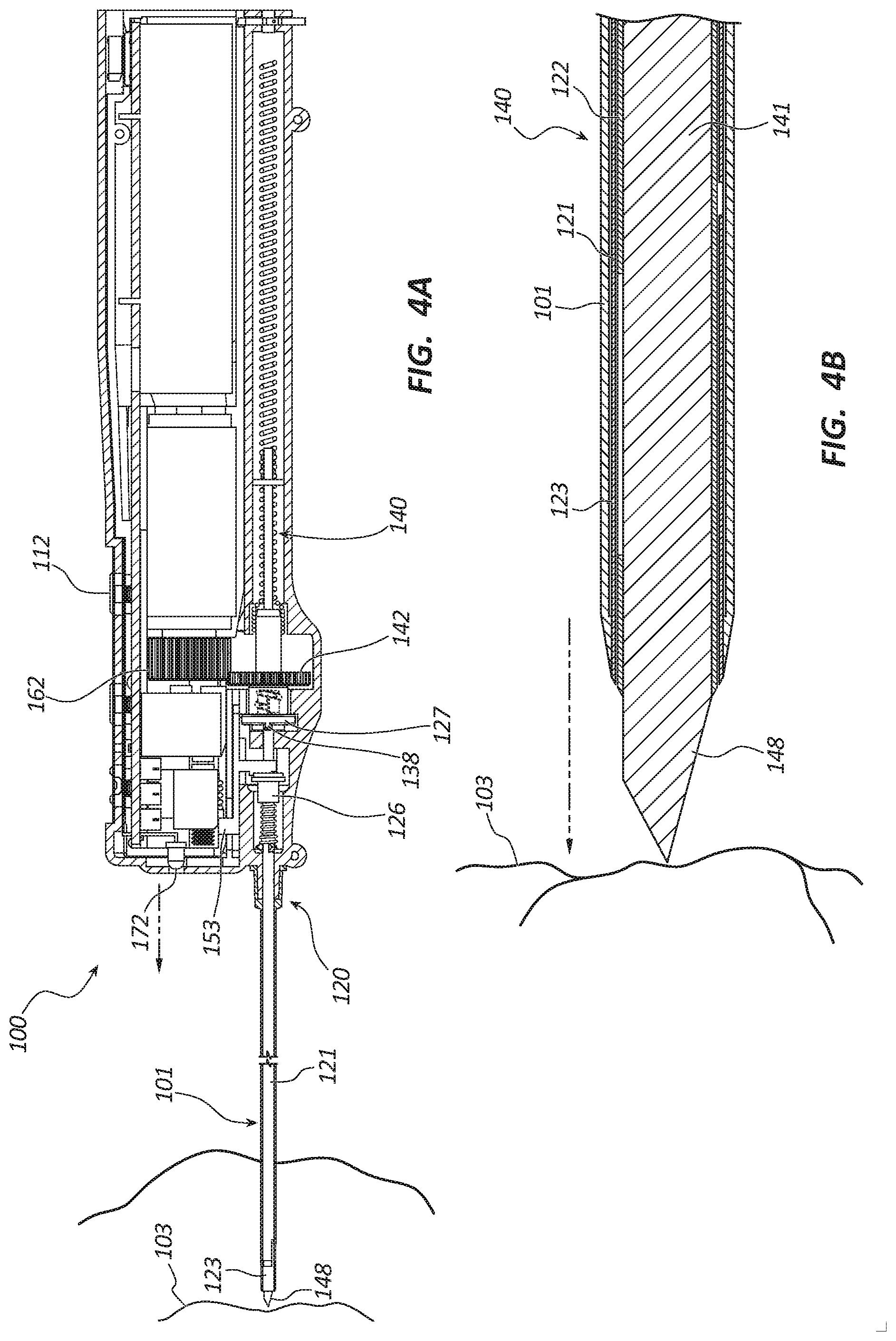
[0045] FIGS. 4A-7B depict an exemplary series of configurations illustrating the tissue sampling tool 100 in use for a particular therapy. More particularly, FIG. 4A depicts the tissue sampling tool 100 in an insertion state and FIG. 4B depicts distal portions of the cannula assembly 120 and the trocar assembly 140 in the insertion state. FIG. 5A depicts the tissue sampling tool 100 in a tissue coring or sampling state and FIG. 5B depicts distal portions of the cannula assembly 120 and the trocar assembly 140 in the tissue coring or sampling state. FIG. 6A depicts the tissue sampling tool 100 in a sample partoff state and FIG. 6B depicts distal portions of the cannula assembly 120 and the trocar assembly 140 in the sample partoff state. FIG. 7A depicts the tissue sampling tool 100 in a tissue sample ejection state and FIG. 7B depicts distal portions of the cannula assembly 120 and the trocar assembly 140 in the tissue sample ejection state.
[0046] Referring to FIG. 4A, the tissue sampling tool 100 is depicted with the distal portions of the cannula assembly 120, trocar assembly 140 and introducer 101 inserted into, and disposed within, a patient's body. In some embodiments, the introducer 101 is not used to insert the tissue sampling tool 100 into the patient's body. The insertion of the tissue sampling tool 100 may be accomplished using any suitable guidance technique. For example, the insertion may be accomplished under ultrasound imaging guidance, under fluoroscopy imaging guidance, using palpation, etc. FIG. 4A further illustrates the handle 110 in the insertion state where the rotation drive member 162 is coupled with the rotation bushing 142, the rotation bushing 142 is positioned distally within a recess of the housing 111 and coupled to the decoupling bushing 127, the actuator 153 is in the neutral state, and the actuation bushing 126 is positioned proximally. The light source 172 may be activated to illuminate the working field or insertion site.
[0047] FIG. 4B shows the distal end 148 of the trocar 141 extending from inner and outer cannulas 122, 121 and disposed adjacent to the lesion 103, the partoff tab 123 in the non-actuated state where the partoff tab 123 does not extend into the lumen of the inner cannula 122 and the coaxial introducer is disposed over the inner and outer cannulas 122, 121.
[0048] Referring to FIG. 5A, the tissue sampling tool 100 is depicted with the distal portions of the cannula assembly 120, trocar assembly 140 and introducer 101 inserted into and disposed within a lesion 103 when obtaining a core tissue sample as the inner and outer cannulas 122, 121 are rotated. FIG. 5A further illustrates the handle 110 in the tissue coring state where rotation of the first motor 161 is activated when the clinician depresses the first or coring button 112. The first motor 161 may be configured to ramp up to speed over a short period of time (e.g., 0.25 second) to prevent torqueing or jerking of the tissue sampling tool 100. During tissue coring, a rotational speed of the first motor 161 may be up to 100% of a maximum rotational speed of the first motor 161. The rotational speed and power to the first motor 161 may be controlled by pulse width modulation. The first motor 161 rotates the rotation drive member 162 which rotates the rotation bushing 142 in a first direction. The rotation bushing 142 rotates the decoupling bushing 127 in the first direction. The decoupling bushing 127 rotates the inner cannula 122 in the first direction. The inner cannula 122 rotates the outer cannula 121 in the first direction. The rotational bushing 142 also rotates the threaded member 144 in the first direction. The nut 145 and the trocar 141 are translated proximally until the nut 145 decouples from the threaded member 144 adjacent the proximal end of the threaded member 144. The distal end 148 of the trocar 141 is disposed within the inner cannula 122. The distal end 148 may be disposed at least 6 cm from the distal end of the outer cannula 121 to accommodate multiple tissue samples. The actuator 153 is in the neutral state, and the actuation bushing 126 is positioned proximally. The light source 172 may be activated to illuminate the working field or insertion site.
[0049] FIG. 5B shows the distal end 148 of the trocar 141 disposed within the inner cannula 122. The circumferentially sharpened distal ends of the inner and outer cannulas 122, 121 and the coaxial introducer 101 are advanced into the lesion as they are rotated, severing a longitudinal portion of the tissue sample. A core tissue sample 104 is procured within the lumen of the inner cannula 122. The partoff tab 123 is in the non-actuated state where the partoff tab 123 does not extend into the lumen of the inner cannula 122.
[0050] Referring to FIG. 6A, the tissue sampling tool 100 is depicted with the distal portions of the cannula assembly 120, trocar assembly 140 and introducer 101 disposed within a lesion 103 at the conclusion of severing of the core tissue sample 104. FIG. 6A further illustrates the handle 110 in the tissue partoff state where the first motor 161 continues to rotate and the partoff tab actuation motor or second motor 151 is activated when the clinician releases digital pressure from the first or coring button 112. The second motor 151 may be configured to ramp up to speed over a short period of time (e.g., 0.25 second) to prevent torqueing or jerking of the tissue sampling tool 100. The first motor 161 continues to rotate resulting in a rotation of the cannula assembly 120 and the trocar assembly 140 in the first direction. The second motor 151 distally translates the actuator drive nut 152. The actuator drive nut 152 engages with the actuator 153 and displaces it distally. The actuator 153 engages with the actuation bushing 126 and displaces it distally. The actuation bushing 126 applies a compressive force to the resilient member 125 and displaces the middle portion 136 of the outer cannula 121 distally, as indicated by the arrow. The middle portion 136 applies a longitudinal force to the partoff tab 123 causing the partoff tab 123 to radially deflect through the aperture 130 into the lumen of the inner cannula 122 while the inner and outer cannulas 122, 121 are rotating as illustrated in FIG. 6B. The deflected partoff tab 123 may sever a distal portion of the core tissue sample 104, separating the sample from the lesion 103. The second motor 151 may be activated until a threshold load is applied by the actuator 153. In another embodiment, the second motor 151 may be activated for a specified period of time. In yet another embodiment, the partoff tab actuation motor 151 may be activated until a threshold voltage is drawn by the second motor 151 to indicate actuation of the partoff tab 123. In still another embodiment, the second motor 151 may be activated until the actuator drive nut 152 triggers a limit switch. Following actuation of the partoff tab 123 and severing of the core tissue sample 104, the first motor 161 and the second motor 151 are deactivated and rotation is stopped. The first motor 161 may continue to rotate for a period of time (e.g., 0.25 second, 0.5 second, or 1.0 second) after the second motor 151 has stopped. The light source 172 may also be deactivated. In certain embodiments, procurement of additional tissue samples may be achieved without removal of the tissue sampling tool 100. The tissue sampling tool 100 may be redirected to a different location within the lesion 103 and the processes of coring and tissue sample severing may be repeated.
[0051] FIG. 6B shows the distal end 148 of the trocar 141 disposed within and proximal to a distal end of the inner cannula 122. The distal end 148 may be disposed proximally at least 6 cm form the distal end of the inner cannula to accommodate one, two, three, four, or more tissue samples 104. As described above, during the initial portion of this step the distal portions of the inner and outer cannulas 122, 121 continue to rotate within the coaxial introducer 101. A core tissue sample 104 is disposed within the lumen of the inner cannula 122. The partoff tab 123 is shown actuated where the partoff tab 123 extends into the lumen of the inner cannula 122. The partoff tab 123 rotates with the inner and outer cannulas 122, 121 relative to the lesion 103 and severs a distal portion of the core tissue sample 104 from the lesion 103.
[0052] Referring to FIG. 7A, the tissue sampling tool 100 is depicted with the distal portions of the cannula assembly 120 and trocar assembly 140 removed from the introducer 101 and patient's body in preparation for ejection of the core tissue sample 104 from the tissue sampling tool 100. FIG. 7A further illustrates the handle 110 in the tissue ejection state where the second or ejection button 113 is depressed by the clinician to activate the second motor 151 to translate the actuator drive nut 152 proximally. The actuator drive nut 152 displaces the actuator 153 proximally from the actuation state to the anti-rotation state. The actuation bushing 126 is displaced proximally by a decompressive force applied by the resilient member 125. The actuation bushing 126 displaces the outer cannula 121 proximally and the partoff tab returns to the undeflected state. The anti-rotation feature 154 of the actuator 153 engages with the nub 138 of the decoupling bushing 127 to prevent rotation of the decoupling bushing 127 and the cannula assembly 120 in the second direction. The rotation bushing 142 is rotated by the first motor 161 in the second direction where it rotationally decouples from the decoupling bushing 127 and translates proximally. The rotation bushing 142 rotates the threaded member 144 in the second direction. A rotational speed of the first motor 161 during tissue sample ejection may be about 30% to about 70%, from about 40% to about 60%, and about 50% of the maximum rotation speed of the first motor 161. The distal end of the threaded member 143 couples with the nut 145 resulting in a distally directed translation of the nut 145 and the trocar 141 to eject the tissue sample 104 from the inner cannula 122. The light source 172 may flash as an indicator of an initiation of ejection of the tissue sample 104.
[0053] FIG. 7B shows the distal portions of the cannula assembly 120 and trocar assembly 140 removed from the patient's body. In some embodiments, the introducer 101 (not shown) may remain inserted into the patient's body to facilitate procurement of additional tissue samples. In certain embodiments, the deflected partoff tab 123, as illustrated in FIG. 6B, may prevent a vacuum force from pulling the tissue sample 104 from the inner cannula 122 when the tissue sampling tool 100 is removed from the patient's body. As depicted in FIG. 7B, the partoff tab 123 is in the undeflected state. The distal end 148 of the trocar 141 is displaced distally to displace the tissue sample 104 from the inner cannula 122. The distal end 148 of the trocar 141 extends from the distal end of the inner and outer cannulas 122, 121. The tissue sample 104 is shown ejected from the cannulas 122, 121. In some embodiments, the tissue sample 104 may be collected on a specimen collection plate or tray. In other embodiments, the tissue sample may be ejected into a tissue preserving fluid, such as formalin, contained within a specimen collection jar.
[0054] FIGS. 8A-8B depict an embodiment of a tissue sampling tool 200 that resembles the tissue sampling tool 100 described above in certain respects. Accordingly, like features are designated with like reference numerals, with the leading digit incremented to "2." For example, the embodiment depicted in FIGS. 8A-8B includes a handle 210 that may, in some respects, resemble the handle 110 of FIG. 1. Relevant disclosure set forth above regarding similarly identified features thus may not be repeated hereafter. Moreover, specific features of the tissue sampling tool 100 and related components shown in FIGS. 1-7B may not be shown or identified by a reference numeral in the drawings or specifically discussed in the written description that follows. However, such features may clearly be the same, or substantially the same, as features depicted in other embodiments and/or described with respect to such embodiments. Accordingly, the relevant descriptions of such features apply equally to the features of the tissue sampling tool 200 and related components depicted in FIGS. 8A-8B. Any suitable combination of the features, and variations of the same, described with respect to the tissue sampling tool 100 and related components illustrated in FIGS. 1-7B can be employed with the tissue sampling tool 200 and related components of FIGS. 8A-8B, and vice versa.
[0055] The tissue sampling tool 200 of FIGS. 8A-8B can include a disposable member 280 as illustrated in FIG. 8A and a reusable member 290 as illustrated in FIG. 8B. The disposable member 280 may include an outer housing 211, a cannula assembly 220, a trocar assembly 240, a coring activation button 212, and an ejection activation button 213 as previously describe relative to tissue sampling tool 100. A cavity within the outer housing 211 is configured to receive the reusable member 290. The outer housing 211 may include a latch disposed at a proximal end of the cavity to retain the reusable member 290 within the cavity. In other embodiments, the outer housing 211 may include an openable and closeable cavity closure or door hingedly coupled to the proximal end of the outer housing 211. In another embodiment, the door may be configured to translate vertically and pivot axially when opened and closed. The disposable member 280 may be configured to be handled by a user and exposed to contaminants, such as bodily fluids, while protecting the reusable member 290 from contamination. The disposable member 280 may be sterilized and presented for use in a sterilized package.
[0056] The reusable member 290 may include an inner housing 215, a power source 270, a rotation member 260, a partoff tab actuating member 250, and a light source 272 as previously described relative to the tissue sampling tool 100. As shown in FIG. 8B, the reusable member 290 may be configured to be disposed within the cavity of the disposable member 280 such that the light source 272 is disposed adjacent a distal end of the outer housing 211. When disposed within the outer housing 211, a light port 214 is aligned with the light source 272 and the rotation member 260 is coupled to the trocar assembly 240.
[0057] Any methods disclosed herein comprise one or more steps or actions for performing the described method. The method steps and/or actions may be interchanged with one another. In other words, unless a specific order of steps or actions is required for proper operation of the embodiment, the order and/or use of specific steps and/or actions may be modified.
[0058] References to approximations are made throughout this specification, such as by use of the term "substantially." For each such reference, it is to be understood that, in some embodiments, the value, feature, or characteristic may be specified without approximation. For example, where qualifiers such as "about" and "substantially" are used, these terms include within their scope the qualified words in the absence of their qualifiers. For example, where the term "substantially perpendicular" is recited with respect to a feature, it is understood that in further embodiments, the feature can have a precisely perpendicular configuration.
[0059] Similarly, in the above description of embodiments, various features are sometimes grouped together in a single embodiment, figure, or description thereof for the purpose of streamlining the disclosure. This method of disclosure, however, is not to be interpreted as reflecting an intention that any claim require more features than those expressly recited in that claim. Rather, as the following claims reflect, inventive aspects lie in a combination of fewer than all features of any single foregoing disclosed embodiment.
[0060] The claims following this written disclosure are hereby expressly incorporated into the present written disclosure, with each claim standing on its own as a separate embodiment. This disclosure includes all permutations of the independent claims with their dependent claims. Moreover, additional embodiments capable of derivation from the independent and dependent claims that follow are also expressly incorporated into the present written description.
[0061] Without further elaboration, it is believed that one skilled in the art can use the preceding description to utilize the invention to its fullest extent. The claims and embodiments disclosed herein are to be construed as merely illustrative and exemplary, and not a limitation of the scope of the present disclosure in any way. It will be apparent to those having ordinary skill in the art, with the aid of the present disclosure, that changes may be made to the details of the above-described embodiments without departing from the underlying principles of the disclosure herein. In other words, various modifications and improvements of the embodiments specifically disclosed in the description above are within the scope of the appended claims. Moreover, the order of the steps or actions of the methods disclosed herein may be changed by those skilled in the art without departing from the scope of the present disclosure. In other words, unless a specific order of steps or actions is required for proper operation of the embodiment, the order or use of specific steps or actions may be modified. The scope of the invention is therefore defined by the following claims and their equivalents.
* * * * *
D00000
D00001
D00002
D00003
D00004
D00005
D00006
D00007
D00008
D00009
XML
uspto.report is an independent third-party trademark research tool that is not affiliated, endorsed, or sponsored by the United States Patent and Trademark Office (USPTO) or any other governmental organization. The information provided by uspto.report is based on publicly available data at the time of writing and is intended for informational purposes only.
While we strive to provide accurate and up-to-date information, we do not guarantee the accuracy, completeness, reliability, or suitability of the information displayed on this site. The use of this site is at your own risk. Any reliance you place on such information is therefore strictly at your own risk.
All official trademark data, including owner information, should be verified by visiting the official USPTO website at www.uspto.gov. This site is not intended to replace professional legal advice and should not be used as a substitute for consulting with a legal professional who is knowledgeable about trademark law.