Multi-configuration Clamp System For Electronic Device
Balmer; Noah
U.S. patent application number 16/865795 was filed with the patent office on 2021-03-18 for multi-configuration clamp system for electronic device. The applicant listed for this patent is Vitec Holdings Italia SRL. Invention is credited to Noah Balmer.
| Application Number | 20210083707 16/865795 |
| Document ID | / |
| Family ID | 1000005241410 |
| Filed Date | 2021-03-18 |


View All Diagrams
| United States Patent Application | 20210083707 |
| Kind Code | A1 |
| Balmer; Noah | March 18, 2021 |
MULTI-CONFIGURATION CLAMP SYSTEM FOR ELECTRONIC DEVICE
Abstract
A support system which allows for the use and mounting of a smart phone, or similar electronic device, in a variety of ways. The support system may be adapted to function as a hand grip while supporting the smart phone during image acquisition, or while watching images on the smart phone. In another configuration, the support system may be adapted to attach to the user's belt. In another configuration, the support system may function as a support stand. In another configuration, the support system may be mounted on a tripod. The support system may include a kit of parts which allow for the modification of support accessories to allow for different configurations. The support system may include a removable shutter which may actuate the camera functions via wireless communication.
| Inventors: | Balmer; Noah; (Santa Rosa, CA) | ||||||||||
| Applicant: |
|
||||||||||
|---|---|---|---|---|---|---|---|---|---|---|---|
| Family ID: | 1000005241410 | ||||||||||
| Appl. No.: | 16/865795 | ||||||||||
| Filed: | May 4, 2020 |
Related U.S. Patent Documents
| Application Number | Filing Date | Patent Number | ||
|---|---|---|---|---|
| 16116925 | Aug 30, 2018 | 10644740 | ||
| 16865795 | ||||
| Current U.S. Class: | 1/1 |
| Current CPC Class: | H04B 2001/3855 20130101; A45F 5/00 20130101; A45F 2005/008 20130101; A45F 5/10 20130101; F16M 11/2021 20130101; A45F 2200/0516 20130101; A45F 5/021 20130101; F16M 13/04 20130101; F16M 11/242 20130101; F16M 11/041 20130101; H04B 1/3877 20130101; H04B 1/385 20130101; F16M 11/40 20130101; A45F 2200/0508 20130101; F16B 2/12 20130101; H04M 1/04 20130101; H05K 5/023 20130101; H04M 1/0264 20130101; F16M 11/10 20130101; H04B 2001/3861 20130101 |
| International Class: | H04B 1/3827 20060101 H04B001/3827; A45F 5/02 20060101 A45F005/02; F16B 2/12 20060101 F16B002/12; F16M 11/04 20060101 F16M011/04; F16M 11/40 20060101 F16M011/40; H04B 1/3877 20060101 H04B001/3877; F16M 11/10 20060101 F16M011/10; F16M 13/04 20060101 F16M013/04; H04M 1/04 20060101 H04M001/04; A45F 5/00 20060101 A45F005/00; A45F 5/10 20060101 A45F005/10; F16M 11/20 20060101 F16M011/20; F16M 11/24 20060101 F16M011/24; H05K 5/02 20060101 H05K005/02 |
Claims
1. A multi-configuration clip system, said system comprising: a central clip portion, said central clip portion comprising: an adjustable length clip, said adjustable length clip adjustable along a first axis, said adjustable length clip adapted to hold a device in a first plane parallel to said first axis, wherein said adjustable length clip has a first end and a second end; and a first locking mechanism adapted to lock the clip at a certain length along said first axis; a support portion, said support portion comprising two parallel tabs extending from a back surface of said central clip portion.
2. The multi-configuration clamp system of claim 2 wherein said adjustable length clip comprises comprises a wireless trigger mount at said first end
3. The multi-configuration clamp system of claim 2 wherein said wireless trigger mount comprises a recessed interface on the first end of the central clip portion.
3. The multi-configuration clip system of claim 1 further comprising a wireless trigger mounted into said wireless trigger mount.
Description
CROSS-REFERENCE TO RELATED APPLICATIONS
[0001] This application is a continuation of U.S. patent application Ser. No. 16/116,925 to Balmer, filed Aug. 30, 2018, which is a continuation of U.S. patent application Ser. No. 15/454,209 to Balmer, filed Mar. 9, 2017, which claims priority to U.S. Provisional Patent Application No. 62/306,589 to Balmer, filed Mar. 10, 2016, which are all hereby incorporated by reference in their entirety.
BACKGROUND
Field of the Invention
[0002] This invention relates to mounting systems, and more specifically to a mounting system and a kit relating to same.
SUMMARY
[0003] A support system which allows for the use and mounting of a smart phone, or similar electronic device, in a variety of ways. The support system may be adapted to function as a hand grip while supporting the smart phone during image acquisition, or while watching images on the smart phone. In another configuration, the support system may be adapted to attach to the user's belt. In another configuration, the support system may function as a support stand. In another configuration, the support system may be mounted on a tripod. The support system may include a kit of parts which allow for the modification of support accessories to allow for different configurations. The support system may include a removable shutter which may actuate the camera functions via wireless communication.
BRIEF DESCRIPTION OF THE DRAWINGS
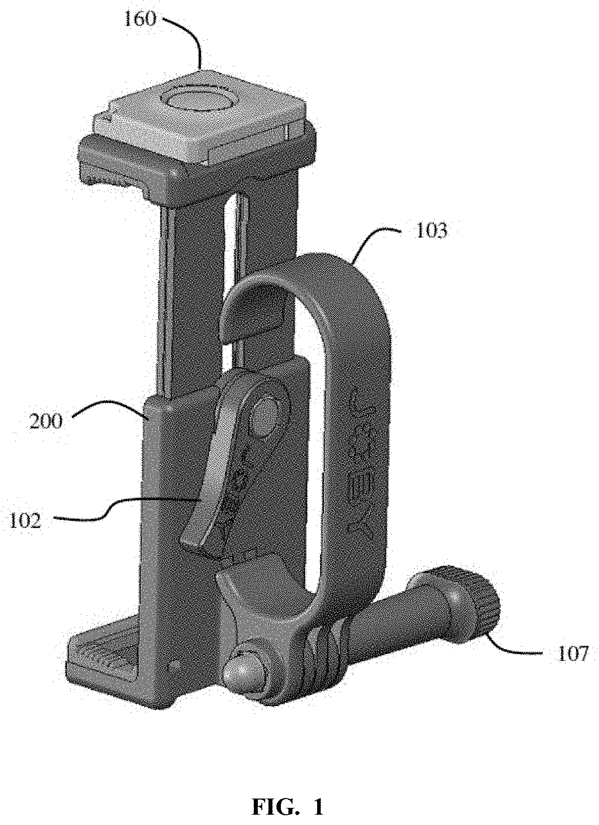
[0004] FIG. 1 illustrates a multi-configuration clip system with a hand grip according to some embodiments of the present invention.
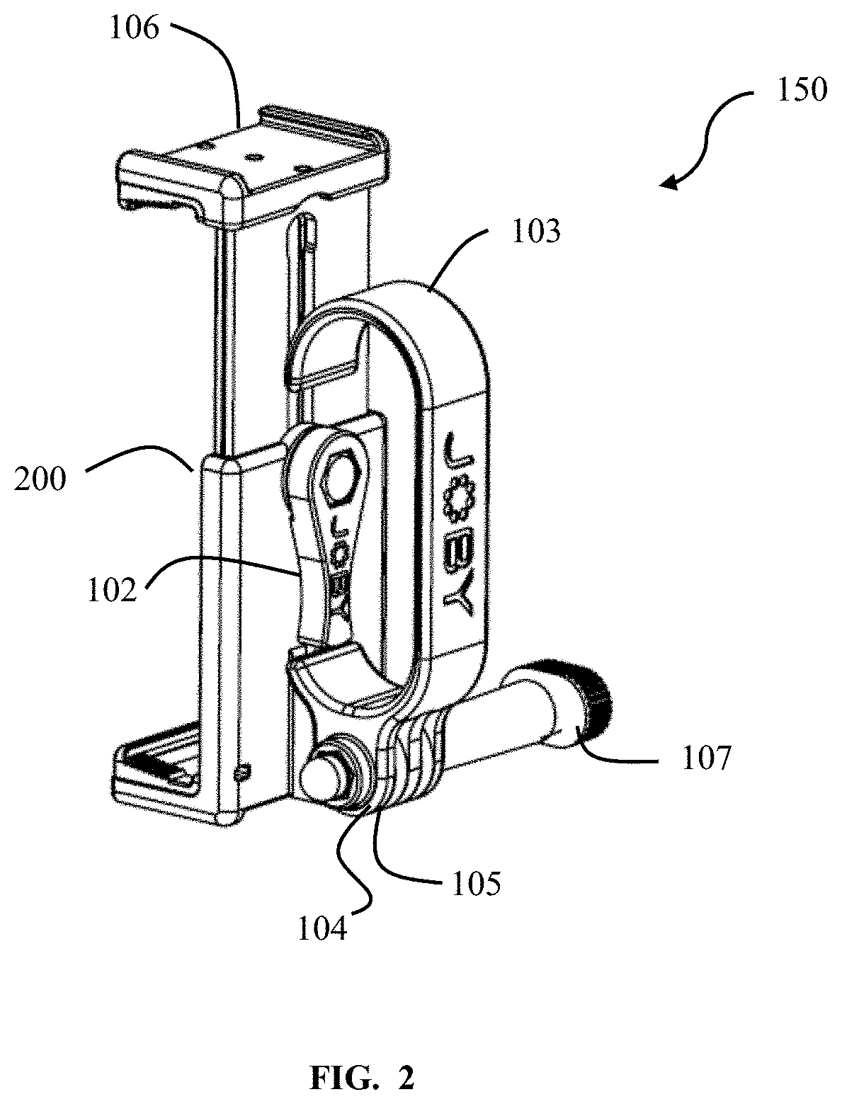
[0005] FIG. 2 illustrates a multi-configuration clip system with a hand grip according to some embodiments of the present invention.
[0006] FIG. 3 is a photograph of a user using a multi-configuration clip system with a hand grip according to some embodiments of the present invention.
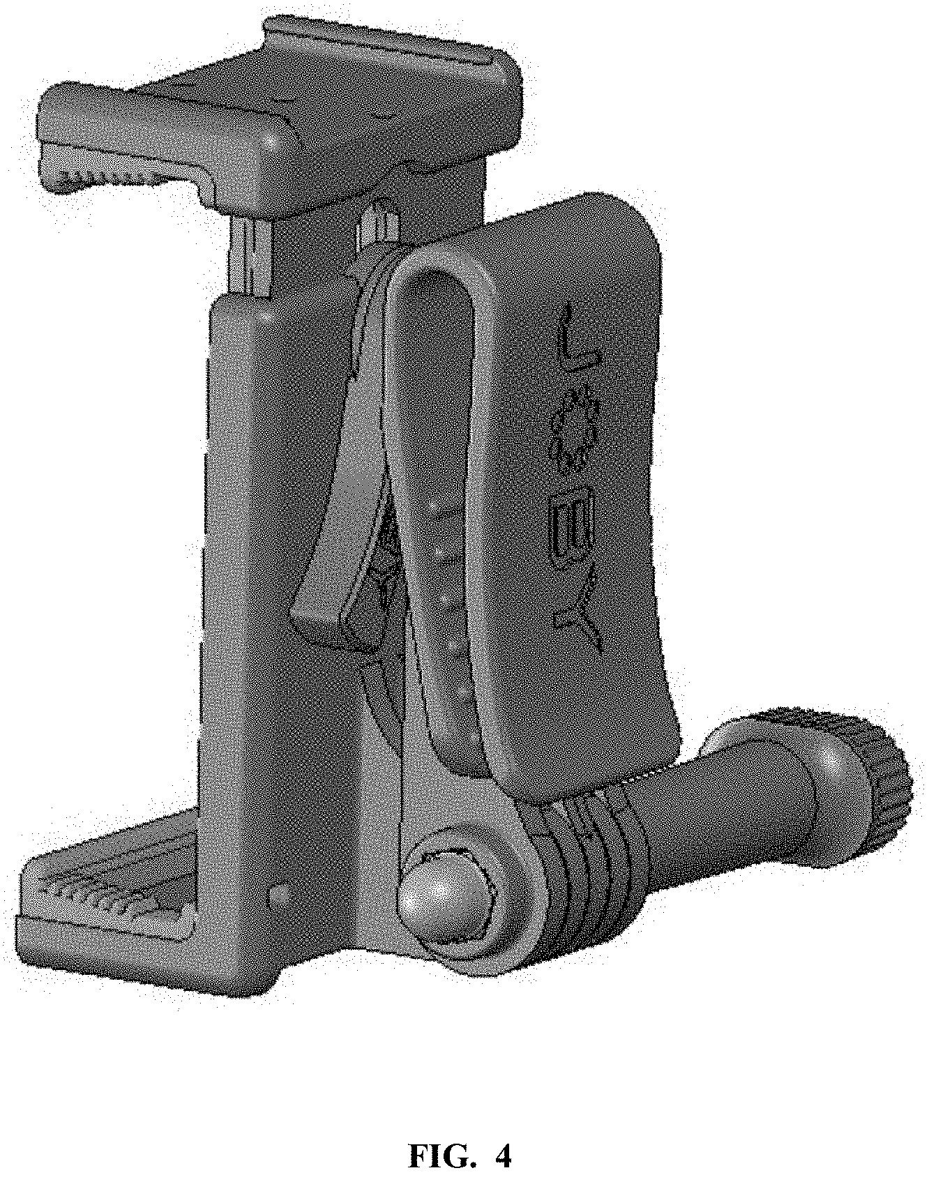
[0007] FIG. 4 illustrates a multi-configuration clip system with a belt clip according to some embodiments of the present invention.
[0008] FIG. 5 illustrates a multi-configuration clip system with a belt clip according to some embodiments of the present invention.
[0009] FIG. 6 is a photograph of a user using a multi-configuration clip system with a belt clip according to some embodiments of the present invention.
[0010] FIG. 7 is a photograph of a user using a multi-configuration clip system with a belt clip according to some embodiments of the present invention.
[0011] FIG. 8 is a photograph of a user using a multi-configuration clip system in an extended configuration according to some embodiments of the present invention.
[0012] FIG. 9 is a photograph of a user using a multi-configuration clip system in an extended configuration according to some embodiments of the present invention.
[0013] FIG. 10 is a photograph of a user using a multi-configuration clip system actuating the trigger in an extended configuration according to some embodiments of the present invention.
[0014] FIG. 11 is a photograph of a multi-configuration clip system in a table top configuration according to some embodiments of the present invention.
[0015] FIG. 12 is a photograph of a multi-configuration clip system on a tripod according to some embodiments of the present invention.
[0016] FIG. 13 is a photograph of a multi-configuration clip system on a tripod according to some embodiments of the present invention.
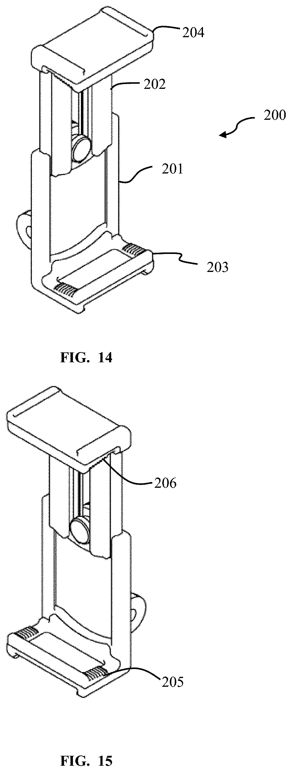
[0017] FIG. 14 illustrates a central clip portion of a multi-configuration clip system according to some embodiments of the present invention.
[0018] FIG. 15 illustrates a central clip portion of a multi-configuration clip system according to some embodiments of the present invention.
[0019] FIG. 16 illustrates a central clip portion of a multi-configuration clip system according to some embodiments of the present invention.
[0020] FIG. 17 illustrates a central clip portion of a multi-configuration clip system according to some embodiments of the present invention.
[0021] FIG. 18 illustrates a trigger according to some embodiments of the present invention.
[0022] FIG. 19 illustrates a belt clip according to some embodiments of the present invention.
[0023] FIG. 20 illustrates a hand grip according to some embodiments of the present invention.
[0024] FIG. 21 illustrates a hand grip according to some embodiments of the present invention.
[0025] FIG. 22 illustrates a multi-configuration clip system with a hand grip according to some embodiments of the present invention.
DETAILED DESCRIPTION
[0026] In some embodiments of the present invention, an adjustable clamp is adapted to grip a smart phone or other device. The central clamp portion may comprise two sliding members adapted to slide along an axis in order to vary the length of the clamp. A locking mechanism is adapted to allow the user to set the length by pushing on a tab. The ends of the central clamp portion may extend perpendicular from the extension axis in order to receive and clamp upon a smart phone. There may be softer pads inside the perpendicular extensions to allow for some gripping as the pads are compressed. In some aspects, a remote trigger may be mounted on one of the ends of the central clamp portion. The remote trigger may be used to activate a shutter or otherwise control imaging of the mounted device.
[0027] As seen in FIGS. 1 and 2, a first configuration 150 of a multi-configuration clamp system includes a central clamp portion 200. The central clamp portion 200 may have interlocking mating pieces adapted to slide along an extension axis to allow for clamping around devices of different cross-sectional dimension. A clamp set lever 102 is adapted to tighten and fasten the two mating pieces of the clamp portion at the desired position. In this first configuration 150 wherein the clamp system is adapted to facilitate hand held operation of a device, a hand grip 103 is coupled to the central clamp portion 200. The central clamp portion 200 has a mounting interface 105. The hand grip 103 also has a mounting interface 104. A clamp mount knob 107 allows for the tightening and fastening of the hand grip 103 to the clamp portion 200. The clamp mount knob 107 may allow for tightening of a threaded feature running cross-wise through the clamp portion mounting interface 105 and the hand grip mounting interface 104. A remote trigger 160 is adapted to fit within a recessed interface 106 on the end of the clamping portion 200 to allow for remote triggering of a camera, or of other functionality.
[0028] FIG. 3 illustrates a first configuration 150 of a multi-configuration clamp system while being held by a user. The central clamp portion has been adjusted to a proper dimension to allow the clamp to clasp the smart phone and has been tightened in this position. The slightly resilient pads inside the perpendicular portions of the clamp allow some compression of the pads, enhancing the clasping of the smart phone. The hand grip is in a position up against the back of the clamping portion and has been tightened in this position. As seen, three of the user's fingers are through the hand grip, but the index finger is at the top of the center clamp portion ready to actuate the wireless trigger. As seen, this configuration allows a user to get a much more convenient, useful, and sure grip on the smart phone and also avoids the user having to use another hand to touch the phone to take a picture. The user may trigger the shutter by tapping on the remote trigger, using the same hand that is also holding the phone in the clamp system.
[0029] As seen in FIGS. 4 and 5, a second configuration 151 of a multi-configuration clamp system includes a central clamp portion 200. The central clamp portion 200 may have interlocking mating pieces adapted to slide along an extension axis to allow for clamping around devices of different cross-sectional dimension. A clamp set lever 102 is adapted to tighten and fasten the two mating pieces of the clamp portion at the desired position. In this second configuration 151 the clamp system is adapted to facilitate belt wearing or standing of a device, a belt clip 111 is coupled to the central clamp portion 200. The central clamp portion 200 has a mounting interface. The belt loop also has a mounting interface 104. A clamp mount knob 107 allows for the tightening and fastening of the belt clip 111 to the clamp portion 200. The clamp mount knob 107 may allow for tightening of a threaded feature running cross-wise through the clamp portion mounting interface 105 and the hand grip mounting interface 104.
[0030] FIGS. 6 and 7 illustrate the second configuration 151 of the clamp system gripping a smart phone while being worn on the belt of a user. The belt clip is rotated all the way back against the central clamp portion.
[0031] FIG. 8-11 illustrate alternate configurations of the multi-configuration clamp system according to embodiments of the present invention. As seen, the hand grip can be placed and tightened into different positions that allow to be used in different ways.
[0032] FIGS. 12 and 13 illustrate the clamp system wherein the central clamp portion is coupled to a tripod interface. In this configuration, the smart phone, or other device, may be positioned in any suitable manner that a tripod, or a flexible tripod, may support it.
[0033] FIGS. 14-17 illustrate aspects of the central clamp portion 200. A first sliding piece 201 mates with and slides along a second sliding piece 202. The first sliding piece 201 may have a perpendicular gripping end 203 with a resilient portion 206. The second sliding piece 202 may have a perpendicular gripping end 204 with a resilient portion 206. The effective length of the central clamp portion may be adjusted by sliding the two sliding pieces relative to each other. Once a desired location is reached, the clamp lock lever 102 may be pushed rotationally to tighten a threaded element, and firmly lock the two sliding pieces together. Both ends of the central clamp portion may have recesses adapted to receive items such as a remote trigger, or other accessory such as a mounting accessory.
[0034] FIG. 18 illustrates a remote trigger 160 with a trigger button 161.
[0035] FIGS. 19 and 20 illustrate a belt clip 111. The belt clip 111 has a belt loop 112 adapted to fasten the clamping system over the belt of a user. FIG. 21 illustrates the hand grip 103. FIG. 22 illustrates the assembly with a hand grip.
[0036] As evident from the above description, a wide variety of embodiments may be configured from the description given herein and additional advantages and modifications will readily occur to those skilled in the art. The invention in its broader aspects is, therefore, not limited to the specific details and illustrative examples shown and described. Accordingly, departures from such details may be made without departing from the spirit or scope of the applicant's general invention.
* * * * *
D00000
D00001
D00002
D00003
D00004
D00005
D00006
D00007
D00008
D00009
D00010
D00011
D00012

D00013

D00014
D00015

D00016

D00017

D00018

D00019

XML
uspto.report is an independent third-party trademark research tool that is not affiliated, endorsed, or sponsored by the United States Patent and Trademark Office (USPTO) or any other governmental organization. The information provided by uspto.report is based on publicly available data at the time of writing and is intended for informational purposes only.
While we strive to provide accurate and up-to-date information, we do not guarantee the accuracy, completeness, reliability, or suitability of the information displayed on this site. The use of this site is at your own risk. Any reliance you place on such information is therefore strictly at your own risk.
All official trademark data, including owner information, should be verified by visiting the official USPTO website at www.uspto.gov. This site is not intended to replace professional legal advice and should not be used as a substitute for consulting with a legal professional who is knowledgeable about trademark law.