Adjusting Support And Projector
Chen; Chanhao ; et al.
U.S. patent application number 16/613136 was filed with the patent office on 2021-03-18 for adjusting support and projector. The applicant listed for this patent is APPOTRONICS CORPORATION LIMITED. Invention is credited to Chanhao Chen, Yi Li.
| Application Number | 20210080813 16/613136 |
| Document ID | / |
| Family ID | 1000005252459 |
| Filed Date | 2021-03-18 |


| United States Patent Application | 20210080813 |
| Kind Code | A1 |
| Chen; Chanhao ; et al. | March 18, 2021 |
ADJUSTING SUPPORT AND PROJECTOR
Abstract
The present disclosure provides an adjustment bracket and a projector, and relates to the technical field of projection devices. The adjustment bracket includes: an adjustment roller; an adjustment foot; and an adjustment foot gear. An adjustment gear is fixed to the adjustment roller, the adjustment gear is engaged with the adjustment foot gear, internal threads are provided at a center position of the adjustment foot gear, an outer wall of the adjustment foot is provided with external threads, and the adjustment foot is connected to the adjustment foot gear by the internal threads and the external threads. A pitch angle or height of an electronic device such as a projector can be adjusted by a combination of a gear transmission and threads, and a structure thereof is simple and an operation thereof is convenient.
| Inventors: | Chen; Chanhao; (Shenzhen, Guangdong, CN) ; Li; Yi; (Shenzhen, Guangdong, CN) | ||||||||||
| Applicant: |
|
||||||||||
|---|---|---|---|---|---|---|---|---|---|---|---|
| Family ID: | 1000005252459 | ||||||||||
| Appl. No.: | 16/613136 | ||||||||||
| Filed: | July 28, 2017 | ||||||||||
| PCT Filed: | July 28, 2017 | ||||||||||
| PCT NO: | PCT/CN2017/094805 | ||||||||||
| 371 Date: | January 8, 2020 |
| Current U.S. Class: | 1/1 |
| Current CPC Class: | G03B 21/145 20130101; F16M 2200/08 20130101; F16M 11/10 20130101; F16M 7/00 20130101; F16M 11/046 20130101 |
| International Class: | G03B 21/14 20060101 G03B021/14; F16M 7/00 20060101 F16M007/00; F16M 11/04 20060101 F16M011/04; F16M 11/10 20060101 F16M011/10 |
Foreign Application Data
| Date | Code | Application Number |
|---|---|---|
| May 17, 2017 | CN | 201710346632.7 |
Claims
1.-10. (canceled)
11. An adjustment bracket, comprising: an adjustment roller; an adjustment foot; and an adjustment foot gear, wherein an adjustment gear is fixed to the adjustment roller, the adjustment gear is engaged with the adjustment foot gear, the adjustment foot gear is provided with internal threads at a center position thereof, the adjustment foot is provided with external threads on an outer wall thereof, and the adjustment foot and the adjustment foot gear are connected through a screw joint of the internal threads and the external threads.
2. The adjustment bracket according to claim 11, wherein the outer wall of the adjustment foot is a non-circumferential structure.
3. The adjustment bracket according to claim 11, wherein the outer wall of the adjustment foot comprises a limit portion and a transmission portion, and the external threads are provided on the transmission portion.
4. The adjustment bracket according to claim 11, wherein a first through hole is provided at the center position of the adjustment foot gear, the internal threads are provided on an inner wall of a lower portion of the first through hole, and a recessed portion is provided at an upper portion of the first through hole.
5. The adjustment bracket according to claim 14, further comprising an upper case and a lower case, wherein the lower case is provided with a protruding arcuate structure, and the protruding arcuate structure is a lower limitation of the adjustment foot gear; an upper portion of the adjustment foot gear is provided with a gear cover, the gear cover is provided with an indention structure adapted to the recessed portion, and the indention structure abuts against the recessed portion.
6. The adjustment bracket according to claim 15, wherein the gear cover is an upper limitation of the adjustment foot gear.
7. The adjustment bracket according to claim 11, wherein the adjustment gear is arranged at an upper end of the adjustment roller and formed into one piece with the adjustment roller.
8. The adjustment bracket according to claim 11, wherein the adjustment gear has a smaller diameter than the adjustment roller.
9. The adjustment bracket according to claim 15, wherein the adjustment roller is arranged at a connection between the upper case and the lower case.
10. The adjustment bracket according to claim 15, wherein the lower case is provided with a second through hole whose shape is adapted to fit with a shape of the outer wall of the adjustment foot, and the adjustment foot penetrates the lower case via the second through hole.
11. The adjustment bracket according to claim 20, wherein the outer wall of a lower portion of the adjustment foot is provided with a limit protrusion.
12. The adjustment bracket according to claim 20, wherein an upper end of the adjustment foot is connected to a first screw, and the first screw is movably arranged in the indention structure.
13. The adjustment bracket according to claim 15, wherein the lower case is provided with a fixation structure for fixing the adjustment roller, and the fixation structure comprises a circular base and a cylindrical support structure; a bottom end of the cylindrical support structure is fixed and connected to the circular base, and a top end of the cylindrical support structure is provided with a second screw.
14. The adjustment bracket according to claim 22, wherein a though hole is provided at a center position of the adjustment roller, and an inner diameter of the through hole is in interference fit with an outer diameter of the cylindrical support structure.
15. The adjustment bracket according to claim 11, wherein a roller decoration part is provided outside the adjustment roller.
16. The adjustment bracket according to claim 25, wherein the roller decoration part covers a part of a periphery of the adjustment roller exposed to outside of a case, and the roller decoration part is provided with an opening for exposing the adjustment roller for adjustment.
17. The adjustment bracket according to claim 11, wherein a lower end of the adjustment foot is further provided with a silicone pad.
18. A projector, comprising: a housing; a projection mechanism provided in the housing; and an adjustment bracket, wherein the adjustment bracket comprises: an adjustment roller; an adjustment foot; and an adjustment foot gear, wherein an adjustment gear is fixed to the adjustment roller, the adjustment gear is engaged with the adjustment foot gear, the adjustment foot gear is provided with internal threads at a center position thereof, the adjustment foot is provided with external threads on an outer wall thereof, and the adjustment foot and the adjustment foot gear are connected through a screw joint of the internal threads and the external threads.
19. An adjustment bracket, comprising: an adjustment roller; an adjustment foot gear; and an adjustment foot connected to the adjustment foot gear through threads wherein an adjustment gear is fixed to the adjustment roller, the adjustment gear is engaged with the adjustment foot gear, the adjustment gear drives the adjustment foot gear to rotate with respect to the adjustment foot, such that the adjustment foot gear is adjusted to move up and down relative to an axis of the adjustment foot.
20. The adjustment bracket according to claim 25, wherein a first through hole is provided at a center position of the adjustment foot gear, an inner wall of a lower portion of the first through hole is provided with internal threads, an outer wall of the adjustment foot is provided with external threads, and the adjustment foot gear and the adjustment foot are connected through a screw joint of the internal threads and the external threads; and wherein the internal threads are provided on an inner wall of a lower portion of the first through hole, and a recessed portion is provided at an upper portion of the first through hole.
Description
TECHNICAL FIELD
[0001] The present disclosure relates to the technical field of electronic devices, and in particular, to an adjustment bracket and a projector.
BACKGROUND
[0002] Projectors are more and more frequently used in education, home, and engineering demonstrations, and people use the projectors to project pictures or videos on a screen or wall to obtain a magnified display. In practical applications, due to limitation of a use environment, it is usually necessary to adjust a pitch angle or height of the projector to obtain a better display effect.
[0003] In the prior art, the projector is provided with a supporting foot at a bottom position that can be rotated to adjust a height, and then the pitch angle or height of the projector can be adjusted by changing a telescopic length of the foot relative to the projector. However, such a design generally requires the user to lift the projector before adjusting the foot, which results in an inconvenient and inaccurate adjustment, and it easily leads to deviation of a placement position of the projector, which is not conducive to adjustment during the projection process.
SUMMARY
[0004] The present disclosure provides an adjustment bracket, including: an adjustment roller; an adjustment foot; and an adjustment foot gear. An adjustment gear is fixed to the adjustment roller, the adjustment gear is engaged with the adjustment foot gear, the adjustment foot gear is provided with internal threads at a center position thereof, the adjustment foot is provided with external threads on an outer wall thereof, and the adjustment foot and the adjustment foot gear are connected through a screw joint of the internal threads and the external threads.
[0005] In another aspect, the present disclosure provides a projector including a housing, a projection mechanism provided in the housing, and an adjustment bracket. The adjustment bracket includes an adjustment roller, an adjustment foot, and an adjustment foot gear. An adjustment gear is fixed to the adjustment roller, the adjustment gear is engaged with the adjustment foot gear, the adjustment foot gear is provided with internal threads at a center position thereof, the adjustment foot is provided with external threads on an outer wall thereof, and the adjustment foot and the adjustment foot gear are connected through a screw joint of the internal threads and the external threads.
[0006] In yet another aspect, the present disclosure further provides an adjustment bracket, including an adjustment roller, an adjustment foot gear, and an adjustment foot connected to the adjustment foot gear through threads. An adjustment gear is fixed to the adjustment roller, the adjustment gear is engaged with the adjustment foot gear, the adjustment gear drives the adjustment foot gear to rotate with respect to the adjustment foot, such that the adjustment foot gear is adjusted to move up and down relative to an axis of the adjustment foot.
[0007] The present disclosure provides an adjustment bracket and a projector. The adjustment bracket includes: an adjustment roller; an adjustment foot; and an adjustment foot gear, wherein an adjustment gear is fixed to the adjustment roller, the adjustment gear is engaged with the adjustment foot gear, the adjustment foot gear, at a center position thereof, is provided with internal threads, the adjustment foot, on an outer wall thereof, is provided with external threads, and the adjustment foot and the adjustment foot gear are connected through a screw joint of the internal threads and the external threads. According to the present disclosure, a pitch angle or height of an electronic device such as a projector can be adjusted by a combination of a gear transmission and threads, and a structure thereof is simple and an operation thereof is convenient.
BRIEF DESCRIPTION OF DRAWINGS
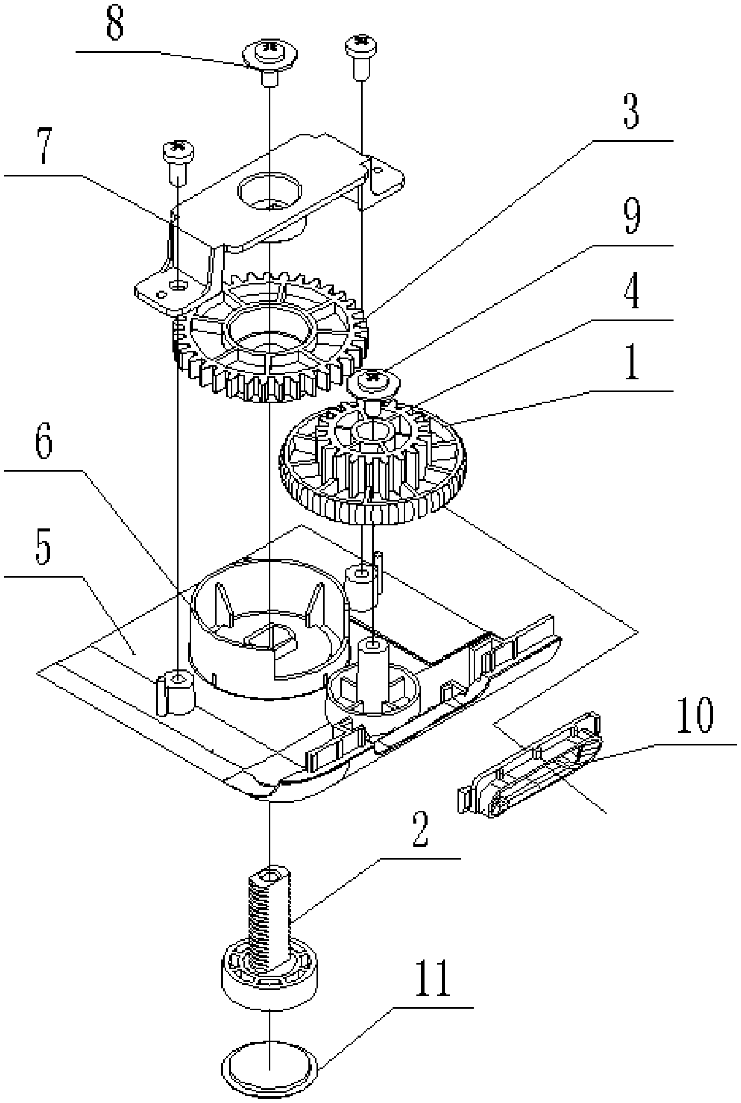
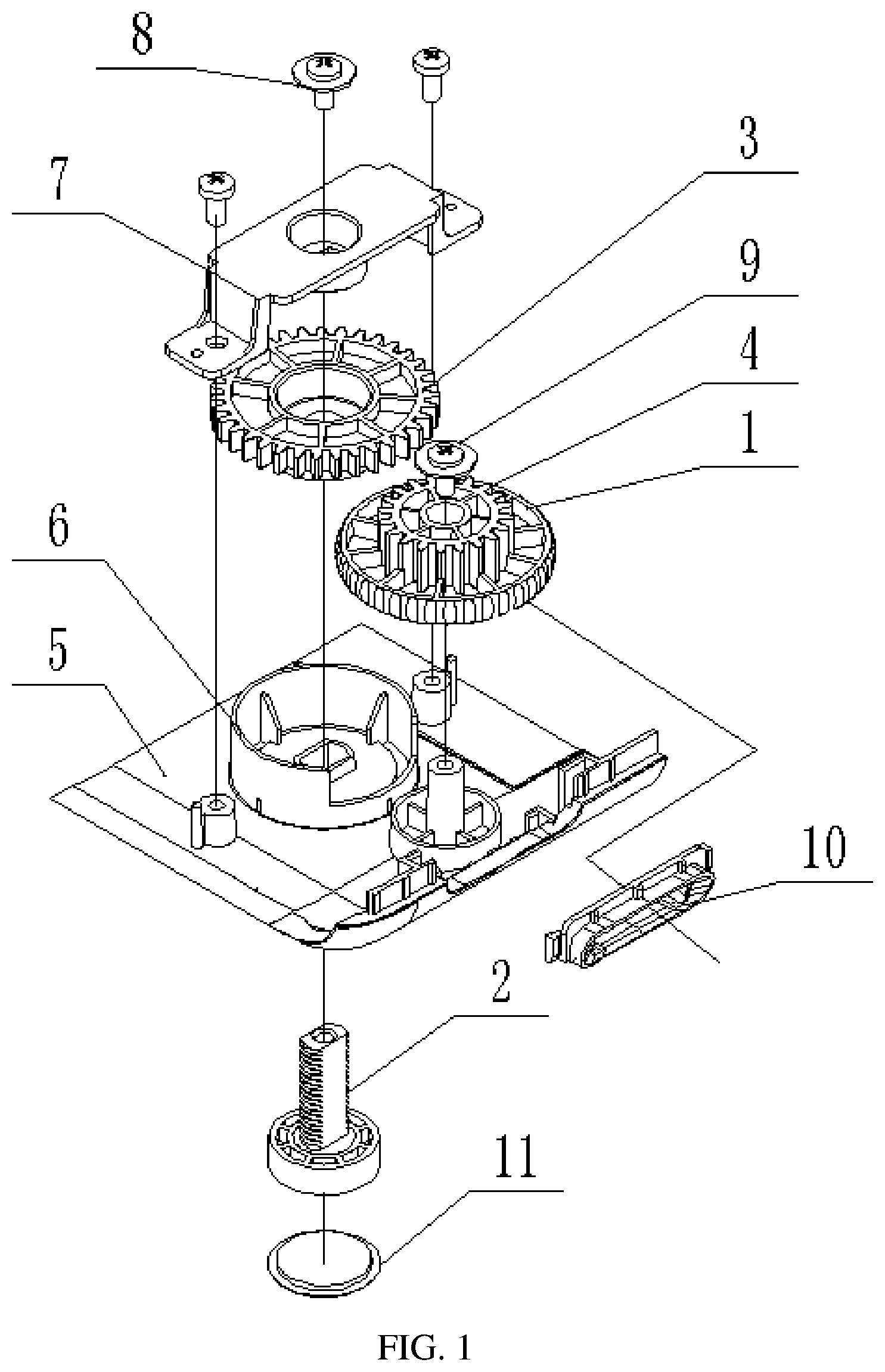
[0008] FIG. 1 is a structural exploded view of an adjustment bracket provided by Example 1 of the present disclosure;
[0009] FIG. 2 is a top view of the adjustment bracket provided by Example 1 of the present disclosure;
[0010] FIG. 3 is a cross-sectional view along A-A of FIG. 2;
[0011] FIG. 4 is an assembly schematic diagram of an adjustment foot gear provided by Example 1 of the present disclosure; and
[0012] FIG. 5 is a schematic diagram of a fixation structure provided by Example 1 of the present disclosure.
[0013] Reference signs:
[0014] 1 adjustment roller; 2 adjustment foot; 3 adjustment foot gear; 4 adjustment gear; 5 lower case; 6 arcuate structure; 7 gear cover; 8 first screw; 9 second screw; 10 roller decoration part; 11 silicone pad.
[0015] The purpose, functional characteristics and advantages of the present disclosure will be described in details with reference to the embodiments and accompanying drawings.
DESCRIPTION OF EMBODIMENTS
[0016] It should be understood that the embodiments described herein are merely for illustrating the present disclosure and not intended to limit the present disclosure.
[0017] In the following description, terms such as "module", "component", or "unit" used for indicating elements are merely for illustration, but not have specific meanings. Therefore, "module" and "component" can represent the same element.
[0018] A main purpose of the present disclosure is to provide an adjustment bracket and a projector, which can achieve an adjustment of a pitch angle or height of an electronic device such as projector by a combination of a gear transmission and threads, a simple structure, and a convenient operation.
Example 1
[0019] As shown in FIG. 1, in this embodiment, an adjustment bracket is provided, and the adjustment bracket includes: an adjustment roller 1, an adjustment foot 2, and an adjustment foot gear 3. An adjustment gear 4 is fixed to the adjustment roller 1, and the adjustment gear 4 is engaged with the adjustment foot gear 3. The adjustment foot gear 3 is provided with internal threads at its central position, and the adjustment foot 2 is provided with external threads at its outer wall. The adjustment foot 2 and the adjustment foot gear 3 are connected through a screw joint of the internal and external threads.
[0020] In the present embodiment, a pitch angle or height of an electronic device such as a projector can be adjusted by a combination of a gear transmission and threads, thereby achieving a simple structure and a convenient operation.
[0021] As shown in FIG. 1, taking a projector as an example, the outer wall of the adjustment foot 2 is provided with a limit portion and a transmission portion, and the external threads are provided on the transmission portion. A first through hole is provided at the center position of the adjustment foot gear 3, the internal thread is provided on an inner wall of a lower portion of the first through hole, and a recessed portion is provided at an upper portion of the first through hole.
[0022] As shown in FIG. 1, in the present embodiment, the limit portion is formed as two mutually parallel flat surfaces, and the transmission portion is formed as two arcuate surfaces connecting the two mutually parallel flat surfaces, so that the outer wall of the adjustment foot is formed as a non-circumferential structure. Such a non-circumferential structure maintains the adjustment foot 2 in a non-rotation state, and the adjustment foot 2 is only allowed to move up and down through threads structure to adjust the height of the projector, thereby adjusting the pitch angle of the projector.
[0023] In another embodiment, the limit portion may be formed as a polygon surface, an arcuate surface, or the like, and the transmission portion may be formed as a spiral surface.
[0024] In this embodiment, an upper case (not shown) and a lower case 5 are provided, and the adjustment roller 1 is disposed at a connection between the upper case and the lower case 5, thereby avoiding a process of grooving and opening a hole in the case. Moreover, such an arrangement is an aesthetic design, and blocks a dust entering path. In this way, a slot for receiving the adjustment roller 1 can be provided only in the lower case 5 or the upper case, thereby reducing a processing complexity.
[0025] As shown in FIG. 2 and FIG. 3, in this embodiment, the adjustment roller 1 is disposed at a side wall of the projector. Most part of the adjustment roller 1 is disposed inside the case of the projector, while only a small part of the adjustment roller 1 is exposed to the operator who operates the roller to rotate, and the adjustment foot gear 3 is driven to rotate by the adjustment gear 4 that is formed in one piece with the adjustment roller 1. When the adjustment foot gear 3 rotates, the adjustment foot gear 3 is fixed in a vertical direction, and thus the adjustment foot gear 3 can only rotate. Since the limit portion of adjustment foot 2 is limited and fixed, the adjustment foot 2 is fixed in a rotation direction and cannot rotate. Therefore, the adjustment foot gear 3 together with a bottom of the case move up and down relative to the adjustment foot 2, thereby adjusting the telescopic length of the adjustment foot 2.
[0026] In the present embodiment, the lower case 5 is provided with a protruding arcuate structure 6, and the arcuate structure 6 is fixed and connected to a lower portion of the adjustment foot gear 3. An upper portion of the adjustment foot gear 3 is provided with a gear cover 7, the gear cover 7 is provided with an indention structure adapted to the recessed portion, and the indention structure abuts against the recessed portion.
[0027] In this embodiment, the lower case 5 is provided with a second through hole adapted to a shape of the outer wall of the adjustment foot 2, and the adjustment foot 2 penetrates the lower case 5 via the second through hole. The outer wall of the adjustment foot 2 is provided with a limit protrusion at a lower end thereof. An upper end of the adjustment foot 2 is connected to a first screw 8, and the first screw 8 is movably arranged in the indention structure by a shim.
[0028] In this embodiment, the first screw 8 is a mechanical flange nail. The shape of the outer wall of the adjustment foot 2 is respectively adapted to a lower portion of the first through hole and to the second through hole.
[0029] As shown in FIG. 4, in this embodiment, the arcuate structure 6, as a lower limitation, limits the adjustment foot gear 3, and the arcuate structure 6 is formed in an arcuate shape instead of a circle shape, so as to provide a receiving space for the adjustment roller 1. The gear cover 7, as an upper limitation, limits the adjustment foot gear 3, and the gear cover 7 is provided with the indention structure and thus provided with a receiving space. Through a design of the recessed portion and the indention structure, there is some space which allows the first screw 8 connected to the adjustment foot 2 moves upward but not exceeds too much from a top surface of the recessed portion and the indention structure, thereby avoiding a design in which a lot of space is reserved for a protrusion of the adjustment foot 2 during a height adjustment process. Further, through the limitations at the lower portion and at the upper portion, when the adjustment roller 1 drives the adjustment gear 4 to rotate, the adjustment gear 4 drives the adjustment foot gear 3 to rotate relative to the adjustment foot 2 so as to move up and down along an axis of the adjustment foot 2. In this way, the adjustment foot gear 3 acts on the arcuate structure on the gear cover 7 or the lower case 5, such that the lower case 5 moves up and down relative to the adjustment foot 2 so as to adjust the telescopic length of the adjustment foot 2 relative to the lower case 5, thereby adjusting the pitch angle or height of electronic devices such as the projector.
[0030] This recess design also provides the adjustment roller 1 with a rotating space, so that an adjustment roller portion of the adjustment roller 1 can be as close as possible to a lower position, close to the lower case 5 (i.e., the adjustment gear 4 is located at an upper position), so that a joint between the upper case and the lower case 5 of the projector is arranged as lower as possible. In this way, an aesthetic design is achieved, and it is convenient for maintenance and disassembly, as the lower case 5 is arranged lower and the parts close to a side of the projector can be maintained in an easier way. Without this recess design, under the same length of the adjustment foot 2 and the same adjustment range of the adjustment foot 2, it is inevitable that a gear surface of the adjustment foot gear 3 will move upward and then the adjustment roller 1 will also move upward.
[0031] As shown in FIG. 5, in this embodiment, the lower case 5 is provided with a fixation structure for fixing the adjustment roller 1.
[0032] In this embodiment, the fixation structure includes a circular base and a cylindrical support structure. A bottom end of the cylindrical support structure is fixed and connected to the circular base. A top end of the cylindrical support structure is provided with a second screw 9.
[0033] In this embodiment, the second screw 9 is a flange self-tapping screw.
[0034] In this embodiment, a through hole is provided at a center position of the adjustment roller 1, and an inner diameter of the through hole is in interference fit with an outer diameter of the cylindrical support structure.
[0035] In this embodiment, a roller decoration part 10 is provided outside the adjustment roller 1, and the roller decoration part 10 partially covers a periphery of the adjustment roller 1. Moreover, the roller decoration part 10 is provided with an opening for exposing and adjusting the adjustment roller 1. The roller decoration part 10 has both decorative and dustproof functions.
[0036] In this embodiment, the lower end of the adjustment foot is further provided with a silicone pad 11.
[0037] In this embodiment, the adjustment bracket may be provided at left and right sides of the projector, respectively, or is merely provided at a front side.
Example 2
[0038] In this embodiment, a projector is provided. The projector includes the adjustment bracket described in Example 1 and conventional structures of the projector, such as an optical structure, a light source structure, a heat dissipation structure and the like. In this embodiment, adjustment of the pitch angle or height of an electronic device such as a projector is achieved by a combination of a gear transmission and threads, and a structure thereof is simple and an operation thereof is convenient.
[0039] It should be noted that, in the present disclosure, terms "including", "comprising" or any other variants thereof are intended to express non-exclusive inclusion. Therefore, a process, method, item or device including or comprising a series of elements includes or comprises not only the mentioned elements, but also other elements that are not explicitly listed, or elements inherent to such a process, method, item or device. Without specific restrictions, an element limited by an expression "including a/an . . . " does not mean that there are no other identical elements in this process, method, item, or device that includes this element.
[0040] The sequence numbers of the examples of the present disclosure described above are merely for description, and do not represent superiority or inferiority of these embodiments.
[0041] Through the description of the above embodiments, those skilled in the art can clearly understand that the methods of the embodiments described above can be implemented by means of software and necessary universal hardware platforms, or only by means of hardware, but in many cases the former is a better implementation manner. Based on such understanding, an essential part of the technical solution of the present disclosure or a part that contributes to the prior art can be embodied in a form of a software product, which is stored in a storage medium (such as ROM/RAM, magnetic disk, optical disc) and includes several instructions for causing a terminal device (such as mobile phone, computer, server, air conditioner, network device) to execute the methods described in the embodiments of the present disclosure.
[0042] The above descriptions are merely embodiments of the present disclosure, and shall not limit a scope of the present disclosure. Any equivalent structure or equivalent process modified using the specification and companying drawings of the present disclosure, or directly or indirectly applied to other related technical fields shall fall within the scope of the present disclosure.
* * * * *
D00000
D00001
D00002
D00003
XML
uspto.report is an independent third-party trademark research tool that is not affiliated, endorsed, or sponsored by the United States Patent and Trademark Office (USPTO) or any other governmental organization. The information provided by uspto.report is based on publicly available data at the time of writing and is intended for informational purposes only.
While we strive to provide accurate and up-to-date information, we do not guarantee the accuracy, completeness, reliability, or suitability of the information displayed on this site. The use of this site is at your own risk. Any reliance you place on such information is therefore strictly at your own risk.
All official trademark data, including owner information, should be verified by visiting the official USPTO website at www.uspto.gov. This site is not intended to replace professional legal advice and should not be used as a substitute for consulting with a legal professional who is knowledgeable about trademark law.