Method And Device For Optical Analysis Of Particles At Low Temperatures
Medoro; Gianni ; et al.
U.S. patent application number 17/247034 was filed with the patent office on 2021-03-18 for method and device for optical analysis of particles at low temperatures. This patent application is currently assigned to Menarini Silicon Biosystems S.p.A.. The applicant listed for this patent is Menarini Silicon Biosystems S.p.A.. Invention is credited to Alex Calanca, Nicol Manaresi, Gianni Medoro.
| Application Number | 20210080374 17/247034 |
| Document ID | / |
| Family ID | 1000005237901 |
| Filed Date | 2021-03-18 |


| United States Patent Application | 20210080374 |
| Kind Code | A1 |
| Medoro; Gianni ; et al. | March 18, 2021 |
METHOD AND DEVICE FOR OPTICAL ANALYSIS OF PARTICLES AT LOW TEMPERATURES
Abstract
Method and device (1b) for performing the optical analysis of particles (2) contained in suspension in a fluid (3) arranged inside a microfluidic device (4) which maintains it at a temperature significantly lower than the ambient temperature; the formation of humidity on the outer surface (8) of the cover of the microfluidic device is avoided by applying a thermal flow (P) which determines an increase in the temperature of the outer surface (8) of the cover to above the condensation temperature (Td), or reduction in the ambient temperature (and/or humidity) in the vicinity of the cover (8), so as to bring the condensation temperature (Td) (dew point) to below the temperature of the surface (8) of the cover determined by the internal operating temperature.
| Inventors: | Medoro; Gianni; (Casalecchio Di Reno, IT) ; Calanca; Alex; (Mirandola, IT) ; Manaresi; Nicol; (Bologna, IT) | ||||||||||
| Applicant: |
|
||||||||||
|---|---|---|---|---|---|---|---|---|---|---|---|
| Assignee: | Menarini Silicon Biosystems
S.p.A. Castel Maggiore IT |
||||||||||
| Family ID: | 1000005237901 | ||||||||||
| Appl. No.: | 17/247034 | ||||||||||
| Filed: | November 24, 2020 |
Related U.S. Patent Documents
| Application Number | Filing Date | Patent Number | ||
|---|---|---|---|---|
| 14353303 | Apr 22, 2014 | |||
| PCT/IB2012/055981 | Oct 29, 2012 | |||
| 17247034 | ||||
| Current U.S. Class: | 1/1 |
| Current CPC Class: | B01L 2300/0645 20130101; B01L 2300/046 20130101; B01L 2300/1827 20130101; B01L 2300/1894 20130101; B01L 2200/0668 20130101; B01L 2300/10 20130101; B01L 3/502761 20130101; G01N 15/1484 20130101; G01N 15/1456 20130101; B01L 3/502715 20130101; G01N 15/1425 20130101; B01L 7/00 20130101 |
| International Class: | G01N 15/14 20060101 G01N015/14; B01L 3/00 20060101 B01L003/00 |
Foreign Application Data
| Date | Code | Application Number |
|---|---|---|
| Oct 28, 2011 | IT | TO2011A000990 |
Claims
1. A method for optical analysis of particles (2) contained in suspension in a fluid, at temperatures lower than dew point temperature, comprising the steps of: i. arranging the particles in suspension within at least one microchamber (4) containing said fluid and delimited between a first and a second surface (5,6); ii. thermally coupling the first surface (5), by means of a first thermal resistance (RLW), to first cooling means (7) adapted to subtract heat from the fluid, and thermally coupling the second surface (6), by means of a second thermal resistance (RHI), to an optical inspection surface (8); iii. bringing said fluid to a first temperature (T1), lower than dew point temperature, by means of said first cooling means; iv. while the particles (2) are being optically analysed, establishing at the optical inspection surface (8) a thermal flow (F) such that the optical inspection surface is constantly maintained at a second temperature (T2) higher than the dew point temperature (Td) of the ambient humidity contained in the air which laps on the optical inspection surface (8); said first and second thermal resistances being chosen so that the second thermal resistance (RHI) has a thermal conductivity value, preferably, at least one order of magnitude lower than that of the first thermal resistance (RLW) and, in any case, equal to at least half the thermal conductivity of the first thermal resistance (RLW).
2. A method according to claim 1, characterized in that step (iv) is carried out by heating the optical inspection surface (8) to above ambient air dew point.
3. A method according to claim 2, characterized in that the optical inspection surface is heated by Joule effect, by arranging on the same, externally to the microchamber (4), a resistor (24b) chosen from the group consisting of: a transparent conductive resistive layer (25), e.g. ITO, applied uniformly on the entire optical inspection surface; a plurality of filiform microresistors (26) arranged on the optical inspection surface, preferably in a comb shape, uniformly spaced from one another.
4. A method according to claim 3, characterized in that said filiform microresistors (26) are supplied so that the current density distribution is homogenous by using a current distribution frame (27) arranged opposite the filiform microresistors, which in turn receives current by means of a plurality of conductor bridges (30), which connect a plurality of different points (28) of the distribution frame, arranged on the side opposite the filiform microresistors, to at least one common collector (31).
5. A method according to claim 2, characterized in that the optical inspection surface (8) is heated by forcing an air flow over the same.
6. A method according to claim 1, characterized in that step (iv) is carried out by cooling an amount of ambient air immediately surrounding the optical inspection surface (8) and so lapping the inspection surface at a temperature such that the dew point (Td) of said amount of air is lower than said second temperature (T2) of the optical inspection surface.
7. A method according to claim 2, characterized in that the temperature of the optical inspection surface is feedback controlled by continuously measuring the instant temperature (T2) of the optical inspection surface, preferably by means of a resistor applied to said optical inspection surface (35), or by means of an infrared sensor arranged facing the optical inspection surface.
8. A method according to claim 7, characterized in that the temperature (T2) at which to maintain the optical inspection surface is calculated as a function of the parameters ambient air temperature and ambient air humidity, which are continuously detected by means of appropriate sensors.
9. (canceled)
10. (canceled)
11. (canceled)
12. (canceled)
13. (canceled)
14. (canceled)
15. (canceled)
Description
TECHNICAL FIELD
[0001] The present invention concerns methods and devices for the manipulation of particles in suspension in a fluid, for example contained in conductive or highly conductive solutions, when optical analysis of the manipulated particles has to be performed at temperatures below ambient temperature. The invention can be applied mainly in the implementation of biological protocols on live cells.
STATE OF THE ART
[0002] The patent application PCT/WO 00/69565 to G. Medoro describes a device and a method for the manipulation of particles via the use of closed dielectrophoretic potential cages. The force used to maintain the particles in suspension or to move them inside the microchamber dissipates, by Joule effect, a power which is proportional to the square of the amplitude of the voltages applied and grows linearly with the increase in the electrical conductivity of the liquid in suspension, causing an uncontrolled increase in temperature inside the microchamber. The manipulation operations can be individually controlled by the programming of memory elements and circuits associated with each element of an array of electrodes integrated in the same substrate; said circuits contribute to the temperature increase, dissipating power in the substrate in direct contact with the suspension liquid. This results in an important limitation due to the variation in the gene expression or to high levels of stress or to the death of the biological particles present in the sample for solutions with high electrical conductivity, limiting the application of these methods and devices to the use of beads or non-live cells.
[0003] The limitations of the known art are overcome by the patent application EP1945368 in the name of the same Applicant, which allows the manipulation of biological particles by means of the technique described in PCT/WO 00/69565 (or by means of other techniques that develop heat) preserving the vitality and biological functions of the cells independently of the forces used and/or the conductivity of the liquid in suspension, therefore allowing the manipulation of live cells.
[0004] However, numerous applications require the suspension liquid and/or all the interior of the microchamber to be maintained, during the manipulation procedure, at temperatures far below the ambient temperature, for example at temperatures below 10.degree. C. and, more frequently, between 3 and 5.degree. C., for example 4.degree. C.
[0005] At such low temperatures ambient humidity condenses on the outer surface of the microchamber cover, which is made of transparent material in order to permit observation and optical analysis of the cells in suspension, either by means of devices or sensors outside the microchamber, for example an optical microscope, or by means of optical sensors inside the microchamber, integrated in the substrate, which, however, require adequate external lighting in order to function correctly.
[0006] The presence of condensed humidity on the microchamber cover causes both blurring of the image that can be acquired from the outside and alteration in the passage of the external light, preventing correct performance of the analysis protocols, unless non-optical internal sensors are relied upon completely, for example impedentiometric sensors, but this is not always possible or convenient.
SUBJECT OF THE INVENTION
[0007] The present invention concerns a method and device for performing the optical analysis of particles contained in suspension in a fluid, typically a liquid, arranged inside a microfluidic device which maintains it at a temperature significantly lower than the ambient temperature and such as to trigger phenomena of condensation on the outer surface of the microfluidic device. Typically, the microfluidic device serves to perform manipulation and/or control of the position of the particles, for example by means of electrical force fields in electrically conductive solutions, and more generally by means of any other system, in conditions that simultaneously require a relatively low operating temperature and performance of an optical analysis of the position and/or appearance of the manipulated particles, or for the detection of morphological parameters or for the quantification of fluorescence intensity. The force fields can be dielectrophoresis (positive or negative), magnetophoresis, electrophoresis, electrohydro-dynamic or electrowetting on dielectric, or combinations of these phenomena, characterised by a set of points of stable equilibrium for the particles. Optical tweezers can also be used.
[0008] The main aspect of the invention concerns prevention of the condensation of humidity on the outer surface of the cover of a microfluidic device operating with a relatively low internal temperature either by increase in the temperature of the outer surface of the cover to above the condensation temperature (dew point), or by lowering the temperature and/or ambient humidity in the vicinity of the cover of the microfluidic device, so as to bring the condensation temperature (dew point) to below the internal operating temperature of the microfluidic device.
[0009] For said purpose, the system can benefit from the use of one or more integrated or external sensors for control of the temperature and, if necessary, of the ambient humidity and temperature of the outer surface of the cover by means of a feedback control.
[0010] The invention furthermore allows the use of external optical systems of the transmission type.
BRIEF DESCRIPTION OF THE FIGURES
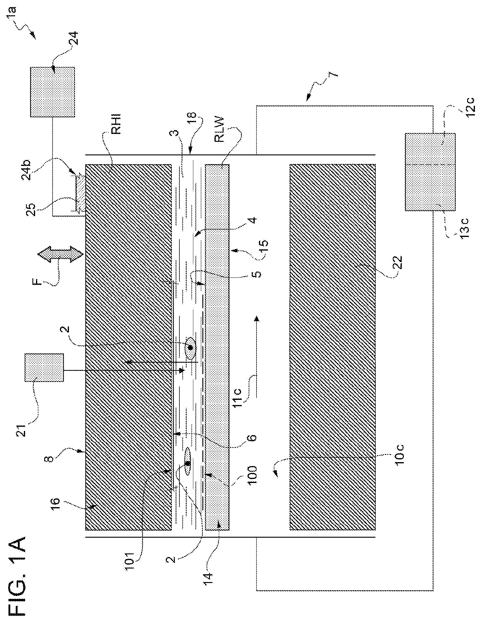
[0011] FIGS. 1A and 1B illustrate schematically in longitudinal section two different embodiments of a microfluidic device which implements a first embodiment of the method of the invention;
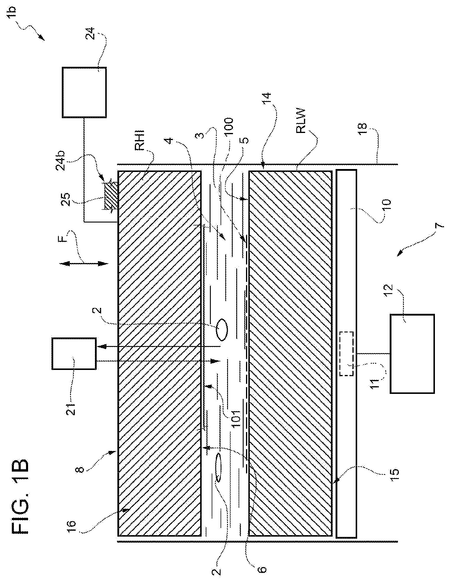
[0012] FIG. 2 illustrates schematically an overhead plan view of an embodiment of the microfluidic device of FIG. 1;
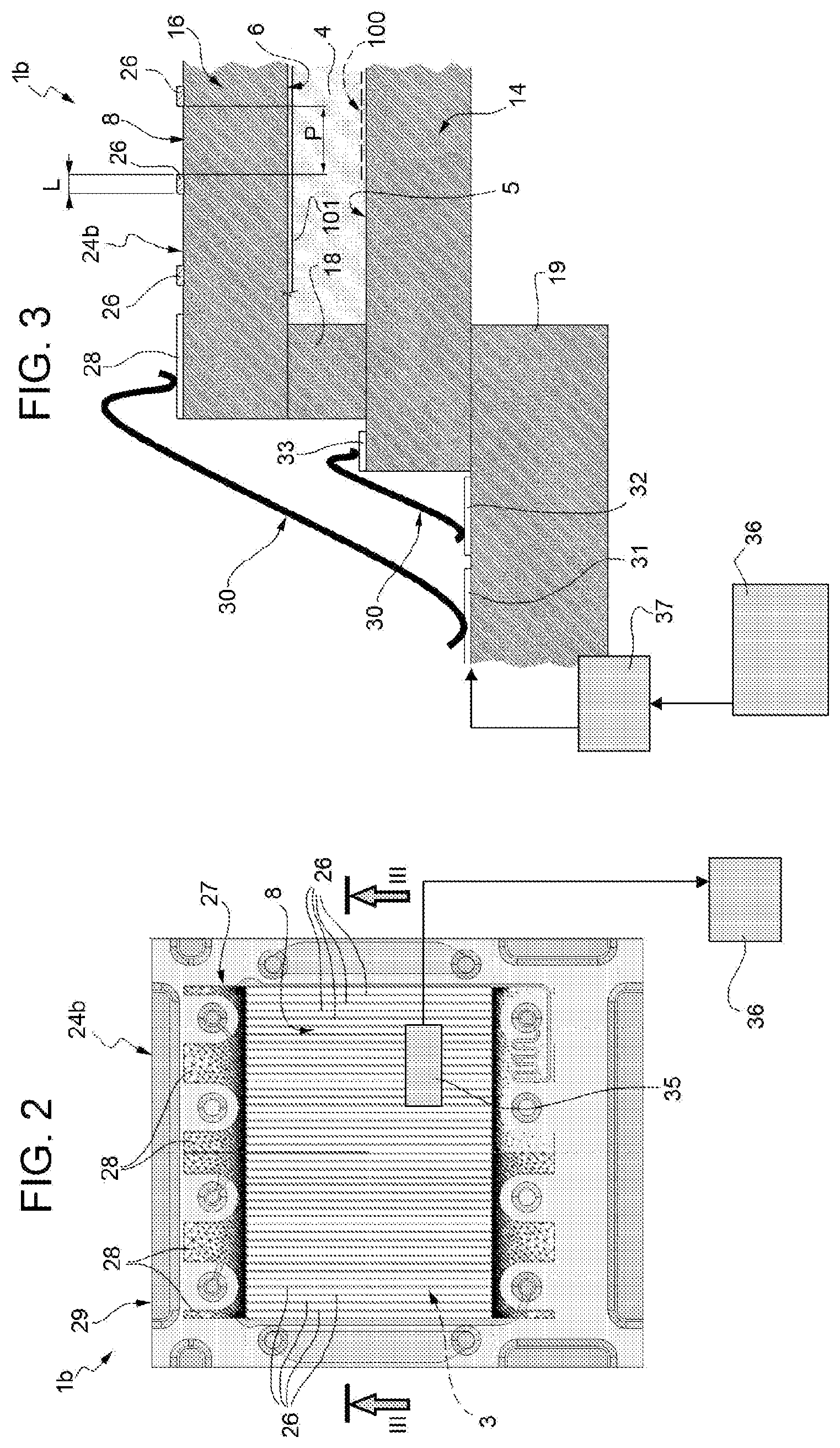
[0013] FIG. 3 illustrates schematically on an enlarged scale a vertical section of the microfluidic device of FIG. 2;
[0014] FIG. 4 is a diagram showing the variation in dew point according to the humidity and temperature of the air;
[0015] FIG. 5 illustrates schematically in longitudinal section a microfluidic device which implements a second embodiment of the method of the invention; and
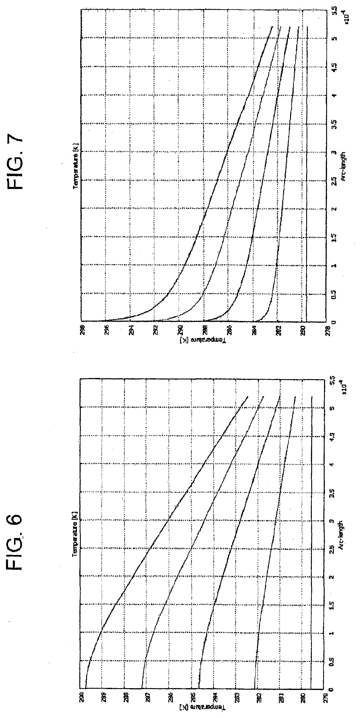
[0016] FIGS. 6 and 7 are diagrams showing the variation in temperature of the upper surface of the microfluidic device of FIG. 2 on the basis of the variation of some operating parameters.
DETAILED DISCLOSURE
[0017] Hereinbelow, the term particles will be used to indicate micrometric or nanometric entities, natural or artificial, such as cells, subcellular components, viruses, liposomes, niosomes, microbeads and nanobeads, or also smaller entities such as macro-molecules, proteins, DNA, RNA, etc., also drops of liquid immiscible in the suspension medium, for example oil in water, or water in oil, or also drops of liquid in gas (such as water in air) or bubbles of gas in liquid (such as air in water).
[0018] The object of the present invention is to provide a method and a device for the optical analysis of particles at temperatures below ambient temperature and, in particular, at relatively low temperatures (3-6.degree. C.), the particles being maintained in suspension in a fluid, typically a liquid, arranged inside a microfluidic device, which also allows manipulation of the particles.
[0019] By manipulation we mean control of the position of single particles or groups of particles or the movement in space of said particles or groups of particles.
[0020] Said manipulation can be performed by any means integrated in the device according to the invention or interacting with it from the outside. Typically the manipulation is performed by means of an array of electrodes, which can be selectively activated and addressed, integrated in a substrate and facing one single counter-electrode which also acts as a cover of the microchamber, according to the description in PCT/WO 00/69565, the content of which is incorporated herein for the necessary parts.
[0021] With reference to the FIGS. 1A, B and 2, the reference number 1a, respectively 1b, indicates a device for performing optical analysis of particles 2 contained in suspension in a fluid 3, typically a liquid, capable of operating by maintaining the particles 2 and the liquid 3 at temperatures below ambient temperature and, in particular, near to zero degrees centigrade, typically temperatures between 3 and 6.degree. C. and preferably at a temperature of approximately 4.degree. C.
[0022] The device 1a, 1b comprises, according to the outlined schematic sketches illustrated in FIGS. 1A and 1B, where similar or identical details are indicated by the same reference numbers for the sake of simplicity, at least one microchamber 4 containing in use the fluid 3 and delimited between a first surface 5 and a second surface 6; and cooling means, indicated overall by 7, thermally coupled with the surface 5 by means of a first thermal resistance RLW.
[0023] By the term "microchamber" we mean here and below a chamber suitable for containing a small volume of fluid 3, typically between 1 nanolitre and 5000 microlitres, and preferably between 1 microlitre and 100 microlitres and having one of its three dimensions measuring less than 1 mm.
[0024] The device 1 furthermore comprises a thermal inspection surface 8 thermally coupled with the surface 6 via a second thermal resistance RHI.
[0025] The cooling means 7 can be of any appropriate type adapted to subtract heat from the microchamber 4 while the device 1a/1b is operative and performs manipulation of the particles 2, in a quantity such as to maintain the fluid 3 at a first pre-set temperature T1, below the ambient temperature, as already indicated typically 4.degree. C.
[0026] In the example illustrated in FIG. 1B, the cooling means 7 consist of a plate 10 arranged in contact with the thermal resistance RLW and in which one or more Peltier cells 11 are integrated (only one of which is shown only schematically, since it is known per se) controlled by a device 12 for controlling the internal temperature of the chamber 4, only schematically represented by a block.
[0027] In the example illustrated in FIG. 1A, on the other hand, the cooling means 7 consist of a second microchamber 10c, in which a flow of coolant 11c runs, in contact with the thermal resistance RLW; said coolant is indicated by an arrow in FIG. 1A and is circulated in a closed circuit from which the heat removed from the microchamber 4 through the surface 5 is continuously eliminated by means of a pump 12c coupled with a Peltier cell, 13c, indicated schematically by a block.
[0028] With reference also to FIGS. 2 and 3, the thermal resistance RLW consists of a flat sheet 14, for example a quartz sheet, transparent if necessary, a first upper face of which consists of the surface 5 and a second lower face of which consists of a surface 15 arranged in contact with the plate 10; the thermal resistance RHI consists of a flat sheet 16, necessarily made of a transparent material, for example consisting of a sheet of mineral glass or quartz, a first face of which, facing the side opposite the microchamber 4, constitutes the optical inspection surface 8, and a second face of which, opposite the first face, constitutes the surface 6.
[0029] The two sheets 14,16 are arranged facing and are separated from each other by a perimeter spacer 18 (indicated schematically only by a line in FIG. 1), which delimits together with the sheets 14,16 the inner volume of the microchamber 4. Either the latter, or the whole unit consisting of the sheets 14,16 and the spacer 18, rests on a base 19 (FIG. 3).
[0030] The device 1a/1b according to the invention also comprises electronic means for manipulating the particles 2 before, during and after optical analysis of the same.
[0031] If dielectrophoresis potential cages, as described in WO 00/69565, are used to manipulate the particles 2, the surface 5 constitutes the substrate which supports an array 100 of microelectrodes, while the surface 6 is entirely coated by an ITO layer 101, which constitutes the counter-electrode. In addition to the microelectrodes of the array 100, one or more optical sensors can be integrated in the substrate to detect any alterations (due for example to the presence of a particle 2) of the ambient light which penetrates into the microchamber 4 through the surface 8. Alternatively or in addition, optical sensors can be provided outside the microchamber 4, for example consisting of a simple microscope 21 of any type, indicated schematically by a block in FIGS. 1A and 1B, which observes the inside of the microchamber 4 through the surface 8. The microscope 21 can identify images and receive any light reflected from the substrate consisting of the surface 5 for example according to the trajectories indicated by the arrows in FIGS. 1A, 1B.
[0032] According to a first embodiment of the invention, the second thermal resistance RHI has a thermal conductivity value of at least one order of magnitude and, preferably, two orders of magnitude, below that of the first thermal resistance RLW; for example, with the materials indicated above, the sheet 14 has a conductivity of approximately 150 W/.degree. K.m while the sheet 16 has a thermal conductivity of only approximately 1.2 W/.degree. K.m.
[0033] In combination with this characteristic, the device 1 furthermore comprises, according to the invention, means 24, indicated schematically by a block in FIG. 1, to establish a thermal flow F (indicated schematically by a double arrow in FIG. 1) at the optical inspection surface 8 such that the surface 8 is constantly maintained at a temperature T2 higher than the temperature Td of condensation of the ambient humidity (dew point) contained in the air which laps in use the optical inspection surface 8.
[0034] As illustrated in the diagram of FIG. 4, the temperature Td can be easily calculated according to the temperature of the ambient air and the amount of humidity present in the ambient air. For mean values usually found in a laboratory (23.degree. C. and 50% humidity), the temperature Td is approximately 12.degree. C. It is evident that since the temperature T1 in the microchamber 4 is approximately 4.degree. C., the temperature of the surface 8 would inevitably reach, in use, by conduction, a temperature lower than Td, producing blurring of the surface 8.
[0035] This phenomenon is avoided according to the invention by the combination of an appropriate choice of the ratio between the thermal conductivities of the thermal resistances RLW and RHI and the simultaneous presence of the means 20. This combination surprisingly allows, on the one hand, as will be seen, a temperature T2 of the surface 8 to be maintained always higher than the temperature Td of the air that laps in use the surface 8, so as to avoid and/or eliminate blurring of the surface 8 when the temperature T1 inside the microchamber 4 is very low. On the other hand, possible heating of the fluid 3 is avoided or at least limited. In fact it has been experimentally shown that even if a "hot" thermal flow reaches the microchamber 4, any increase in the temperature T1 can be easily avoided by lowering the temperature set by the control unit 12 on the Peltier cell 11 without triggering undesired convective motions inside the microchamber 4.
[0036] According to a first possible embodiment of the invention, the device 1b (or 1a) comprises means 24b(FIGS. 2,3) to heat the optical inspection surface 8 to above the dew point of the ambient air, or above the temperature Td.
[0037] Said means 24b consist in a resistor directly applied integrally in one piece on the surface 8 of the sheet 16. According to an embodiment example illustrated only schematically and only partly in FIG. 1, the resistor 24b consists of a transparent conductive resistive layer 25, for example ITO, applied uniformly over the whole optical inspection surface 8.
[0038] In a second possible embodiment of the invention, the resistor 24b consists of at least one and preferably a plurality of filiform microresistors, or wires, 26 applied integrally in one piece to the optical inspection surface 8, preferably arranged in a comb shape and uniformly spaced from one another.
[0039] The filiform microresistors 26 are electrically connected, each at the same one end thereof, to a distribution frame 27 of the electrical supply current, consisting of a metal foil in a comb shape, but arranged opposite the filiform microresistors 26; in other words, respective "teeth" 28 of the comb-shaped metal foil 27 face the side opposite the wires 26 and extend outside the surface 8, being arranged on one edge 29 of the device 1 outside the operating area consisting of the microchamber 4.
[0040] The frame 27 receives the electrical supply current through the "teeth" 28, by means of a plurality of conductor bridges 30 which connect a plurality of different points of the frame 27, consisting of the "teeth" 28, to at least one common collector 31 arranged at the base element 19 of the device 1.
[0041] The conductor bridges 30 consist of deformable metal wires bent to form S-shaped frames or forks on the plane of FIG. 3. The electrical supply of the electrodes and any optical sensors in the substrate that may be present on the surface 5 is also provided by bridges 30, using other collectors 32,33.
[0042] To allow the device 1b (1a) to operate correctly, i.e. to maintain the temperature T2 above the temperature Td of the air that laps in use the surface 8 without excessive heat loss towards the microchamber 4, to maintain the temperature of the entire surface 8 as uniform as possible and not interfere with the integrated optical sensors and/or with the external sensors, like the microscope 21, the filiform microresistors 26 must have a width L (FIG. 3) equal to approximately one tenth of the pitch P (i.e. the spacing) between the same in a direction transverse to their longitudinal extension. In other words, the L/D ratio must be preferably equal to 1/10 and in any case be between 1/2 and 1/100.
[0043] To improve the performance of the device 1b (1a), it preferably also comprises means 35 (FIG. 2) to continuously measure in use the temperature T2 of the surface 8 and means 36 to operate in feedback the means 24b to heat the optical inspection surface; for example the temperature detection means 35 can consist of an electrical resistance applied on the surface 8, which varies its resistivity according to the temperature T2, or of an optical sensor arranged facing the surface 8; in the first case, one of the filiform microresistors 26 can be used as the electrical resistance, making the appropriate electrical connections. The means 36 consist of the microprocessor which controls all the functions of the device 1b (1a) or of a dedicated microprocessor, and they interact for example with a power supply unit 37 (FIG. 3) which controls the current supplied to the frame 27 via the bridges 30. There must be a large, number of the latter, so that the spacing intervals there between make the temperature on the opposite side of the sheet 16 substantially uniform.
[0044] Observing the parameters indicated, the trend of the temperature gradient through the thickness of the sheet 16 for different levels of electrical power supplied to the wires or "fingers" 26 is the one shown in FIG. 6, which represents the worst scenario, in other words in the middle of the pitch P, i.e. the temperature at the surface area 8 without resistors comprised between two filiform microresistors or "fingers" 26, and in FIG. 7, which shows the best scenario, i.e. the temperature directly below a microresistor or "finger" 26. The temperature gradient that can be maintained through the sheet 16, taking account of the heat losses towards the outside, allows a temperature very close to T1 to be maintained on the surface 6, while the temperature T2 on the surface 8 is uniformly higher than the temperature Td.
[0045] For this purpose, and independently of the embodiment of the heating means 24b, it is also convenient for the thickness of the sheet 16 to be determined at the project stage using the following formula:
H lid > ( T dp - T 0 - .DELTA. T max .DELTA. T max ) ( .sigma. lid .sigma. buf ) H C ( 1 ) .DELTA. T max = ( T buf - T 0 ) max ( 2 ) ##EQU00001##
where H.sub.lid and H.sub.c are respectively the thickness of the sheet constituting the cover of the microchamber 4 and the thickness of the microchamber 4 itself, T.sub.dp is the dew point temperature of the ambient air, T.sub.o is the theoretical operating temperature desired inside the microchamber 4, T.sub.buf coincides with the temperature T1, i.e. it is the temperature of the liquid 3, .DELTA.T.sub.max is the maximum increase in temperature tolerable inside the microchamber 4 with respect to the theoretical operating temperature T.sub.o,.sigma..sub.lid and .sigma..sub.buf are the thermal conductivity of the material of the sheet 16 and of the liquid (buffer) 3 respectively.
[0046] With reference to FIG. 5, where the details similar or identical to those already described are indicated by the same numbers, the device 1b comprises heating means 24c located outside the sheet 16 and consisting in the example illustrated of a fan 40 and a resistance 41 which, controlled by the control unit 36 connected to a sensor 35 of the temperature T2 of the surface 8 heat the latter, sending to it a flow of ambient air.
[0047] On the basis of the description, the invention therefore also concerns a method for performing the optical analysis of particles 2 contained in suspension in a fluid 3, at temperatures below the ambient temperature, comprising the steps of:
i.--arranging the particles 2 in suspension inside at least one microchamber 4 containing the fluid 3 in a space delimited between the surfaces 5 and 6; ii.--thermally coupling the surface 5, via the thermal resistance RLW, with the cooling means 7 adapted to subtract heat from the fluid 3, and thermally coupling the surface 6, via the thermal resistance RHI, with the optical inspection surface 8 to be maintained clear; iii.--bringing the fluid 3 to the temperature T1, lower than the ambient temperature, by means of the cooling means 7; and iv.--while the particles 2 are being optically analysed, establishing at the optical inspection surface 8 a thermal flow F such that the optical inspection surface 8 is constantly maintained at the temperature T2, higher than the temperature Td of condensation of the ambient humidity (dew point) contained in the air which laps the optical inspection surface; v.--where the thermal resistances RHI and RLW are chosen so that the thermal resistance RHI has a thermal conductivity value preferably at least one order of magnitude below that of the first thermal resistance RLW and, in any case, equal to at least half of the thermal conductivity of the thermal resistance RLW.
[0048] Typically, the thermal flow F is an input thermal flow, in the sense that step (iv) is performed by heating the optical inspection surface 8 to above the dew point of the ambient air, as previously illustrated.
[0049] Heating of the surface 8 can be obtained, preferably, by Joule effect, providing on the same, outside the microchamber 4, a resistor 24b chosen from the group consisting of: a transparent conductive resistive layer, for example of Indium Tin Oxide (ITO, or based on nano tubes of carbon, or conductive polymers such as poly(3,4-ethylenedioxythiophene) (PEDOT)) 25 uniformly applied over the entire optical inspection surface 8; a plurality of filiform microresistors 26 applied on the optical inspection surface 8, arranged in a comb shape, uniformly spaced from one another transverse to the direction of longitudinal extension of the microchamber 4.
[0050] The filiform microresistors 26 which, according to an embodiment not illustrated for the sake of simplicity, can also be arranged in a grid pattern, or so as to cross one another, are in any case supplied so that the current density distribution is uniform; in the case illustrated, using the current distribution frame 27 arranged longitudinally orthogonal to the filiform microresistors 26, which in turn receives the current by means of a plurality of conductor bridges 30 which connect a plurality of different points 28 of the distribution frame 27, arranged on the side opposite the filiform microresistors 26, to at least one common collector 31.
[0051] Alternatively, as has been seen, the optical inspection surface 8 is maintained at a temperature higher than the dew point by forcing an air flow over the same by forced convection, generated for example by a fan 40. Said flow counters the lowering of the temperature of the optical inspection surface 8 due to the absorption of heat by the cooling system through the liquid in the microchamber 4, as illustrated in FIG. 5.
[0052] In any case, heating of the optical inspection surface 8 is preferably feedback controlled by continuously measuring the current temperature T2 of the same, preferably by means of a resistance 35 applied to the optical inspection surface 8 or by means of an infrared sensor arranged facing the optical inspection surface 8.
[0053] According to a different embodiment of the invention, however, the step (iv) can be performed equally effectively by cooling a quantity of ambient air immediately surrounding the optical inspection surface 8 which laps the same, at a temperature T3 such that the dew point of said quantity of air becomes lower than the temperature T2 of the optical inspection surface 8 due to thermal transmission by conduction from and to the microchamber 4 through the thickness of the sheet 16.
[0054] A solution of this kind can be implemented by a device 1b (or 1a) similar to the one illustrated schematically in FIG. 5, where a fan 40 is used to recirculate the same quantity of air present in the vicinity of the surface 8 through a cooling element 41, for example consisting of a set of Peltier cells all arranged around the sheet 16.
[0055] The temperature Td, especially in the implementations previously described, can be fixed beforehand, taking 12.degree. C. as a fixed estimate, which is the value that occurs in the majority of cases. Vice versa, the actual temperature Td of the ambient air and the cooled air which laps the surface 8 due to the action of the fan 40 is calculated, for example, by detecting both the temperature and ambient humidity, and those of said cooled air, by means of appropriate sensors 42 connected to the control unit 36.
[0056] Obviously the cooling caused by the set of Peltier cells which establishes the required thermal flow F according to the invention can be used to lower both the temperature and humidity of the ambient air, or only the temperature or only the humidity.
* * * * *
uspto.report is an independent third-party trademark research tool that is not affiliated, endorsed, or sponsored by the United States Patent and Trademark Office (USPTO) or any other governmental organization. The information provided by uspto.report is based on publicly available data at the time of writing and is intended for informational purposes only.
While we strive to provide accurate and up-to-date information, we do not guarantee the accuracy, completeness, reliability, or suitability of the information displayed on this site. The use of this site is at your own risk. Any reliance you place on such information is therefore strictly at your own risk.
All official trademark data, including owner information, should be verified by visiting the official USPTO website at www.uspto.gov. This site is not intended to replace professional legal advice and should not be used as a substitute for consulting with a legal professional who is knowledgeable about trademark law.