User Experience System For Improving Compliance Of Temperature, Pressure, And Humidity
Brown; Julie Joanne ; et al.
U.S. patent application number 17/024404 was filed with the patent office on 2021-03-18 for user experience system for improving compliance of temperature, pressure, and humidity. The applicant listed for this patent is Johnson Controls Technology Company. Invention is credited to Julie Joanne Brown, Rachel D. M. Ellerman, Renee R. Jacobs, Caroline T. Moore, Victoria M. Toner.
| Application Number | 20210080139 17/024404 |
| Document ID | / |
| Family ID | 1000005131381 |
| Filed Date | 2021-03-18 |


View All Diagrams
| United States Patent Application | 20210080139 |
| Kind Code | A1 |
| Brown; Julie Joanne ; et al. | March 18, 2021 |
USER EXPERIENCE SYSTEM FOR IMPROVING COMPLIANCE OF TEMPERATURE, PRESSURE, AND HUMIDITY
Abstract
A building management system (BMS) for heating, ventilation, or air conditioning (HVAC) parameters in a building. The BMS includes one or more processing circuits including one or more memory devices coupled to one or more processors. The one or more processors query a training data storage and receive training data, institute a policy with a machine learning engine and train the policy using the training data, receive temperature, pressure, and humidity (TPH) sensor data from one or more sensors, determine a fault based on the TPH sensor data, provide the TPH sensor data and the fault to the policy of the machine learning engine and output a corrective action to resolve the fault, and generate a work order for a user based on the TPH sensor data, the determined fault and the corrective action.
| Inventors: | Brown; Julie Joanne; (Yardley, PA) ; Jacobs; Renee R.; (Leawood, KS) ; Toner; Victoria M.; (Port Washington, WI) ; Ellerman; Rachel D. M.; (Shorewood, WI) ; Moore; Caroline T.; (Decatur, GA) | ||||||||||
| Applicant: |
|
||||||||||
|---|---|---|---|---|---|---|---|---|---|---|---|
| Family ID: | 1000005131381 | ||||||||||
| Appl. No.: | 17/024404 | ||||||||||
| Filed: | September 17, 2020 |
Related U.S. Patent Documents
| Application Number | Filing Date | Patent Number | ||
|---|---|---|---|---|
| 62902338 | Sep 18, 2019 | |||
| Current U.S. Class: | 1/1 |
| Current CPC Class: | G06Q 50/163 20130101; G05B 2219/2614 20130101; F24F 11/64 20180101; F24F 11/65 20180101; F24F 11/38 20180101; G06Q 10/0631 20130101; G05B 19/042 20130101 |
| International Class: | F24F 11/38 20060101 F24F011/38; G06Q 10/06 20060101 G06Q010/06; G06Q 50/16 20060101 G06Q050/16; G05B 19/042 20060101 G05B019/042; F24F 11/64 20060101 F24F011/64; F24F 11/65 20060101 F24F011/65 |
Claims
1. A building management system (BMS) for heating, ventilation, or air conditioning (HVAC) parameters in a building, the BMS comprising: one or more processing circuits comprising one or more memory devices coupled to one or more processors, the one or more memory devices configured to store instructions thereon that, when executed by the one or more processors, cause the one or more processors to: institute a policy with a machine learning engine and train the policy using training data, receive temperature, pressure, and humidity (TPH) sensor data from one or more sensors, determine a fault based on the TPH sensor data, provide the TPH sensor data and the fault to the policy of the machine learning engine and output a corrective action to resolve the fault, and generate a work order for a user based on the TPH sensor data, the determined fault, and the corrective action, and.
2. The BMS of claim 1, wherein the user interface includes a first user profile and a second user profile, and wherein the one or more memory devices are further configured to store instructions thereon that, when executed by the one or more processors, cause the one or more processors to: generate a first dashboard associated with the first user profile and a second dashboard associated with the second user profile, provide a first subset of information from the work order to the first dashboard, and provide a second subset of information from the work order to the second dashboard.
3. The BMS of claim 2, wherein the one or more memory devices are further configured to store instructions thereon that, when executed by the one or more processors, cause the one or more processors to: update the second dashboard based on an action entered on the first dashboard.
4. The BMS of claim 2, wherein the work order is stored within the one or more memory devices, and wherein the one or more memory devices are further configured to store instructions thereon that, when executed by the one or more processors, cause the one or more processors to: update the work order from either the first dashboard or the second dashboard.
5. The BMS of claim 2, wherein the one or more memory devices are further configured to store instructions thereon that, when executed by the one or more processors, cause the one or more processors to: assign the work order to the second dashboard from the first dashboard.
6. The BMS of claim 2, further comprising an application structured to access one of the first user profile or the second user profile and display the associated dashboard on a human machine interface, the associated dashboard displaying at least one of the TPH sensor data or the work order.
7. The BMS of claim 6, wherein the human machine interface includes a mobile device, a wall mounted panel, a monitor, a tablet, a kiosk, an augmented reality device, a virtual reality device, or a wearable device.
8. The BMS of claim 1, wherein the one or more memory devices are further configured to store instructions thereon that, when executed by the one or more processors, cause the one or more processors to: retrieve a fault causation template, map a plurality of operational parameters relating to an associated HVAC device to the fault causation template, map the corrective action to the fault causation template, and provide a populated fault causation template to the user interface.
9. The BMS of claim 1, wherein the one or more memory devices are further configured to store instructions thereon that, when executed by the one or more processors, cause the one or more processors to: receive a notification that the work order has been completed, the notification comprising the determined fault and a fault solution, wherein the fault solution is either the corrective action or a different action, and train the policy with the machine learning engine by providing the determined fault and the fault solution to the machine learning engine.
10. The BMS of claim 1, wherein the machine learning engine includes at least one of a neural network, a reinforcement learning scheme, a model-based control scheme, a linear regression algorithm, a decision tree, a logistic regression algorithm, and a Naive Bayes algorithm.
11. The BMS of claim 1, wherein the user is one of a chief compliance officer, a facilities manager, an operating room administrator, a health care professional or a facilities technician.
12. The BMS of claim 1, wherein the one or more memory devices are further configured to store instructions thereon that, when executed by the one or more processors, cause the one or more processors to: provide the work order to a user interface, receive an indication that the work order has been completed, and updating the user interface to indicate that the work order has been completed.
13. The BMS of claim 1, wherein the one or more memory devices are further configured to store instructions thereon that, when executed by the one or more processors, cause the one or more processors to: provide assistance functionality to the user interface, receive a request for assistance from the user interface via the assistance functionality, and provide additional information related to the corrective action to the user interface.
14. The BMS of claim 1, wherein the one or more memory devices are further configured to store instructions thereon that, when executed by the one or more processors, cause the one or more processors to: provide an alert in the building in response to determining the fault, wherein the alert includes at least one of a visual alert, an audible alert, a fault indication, and corrective action indication.
15. A building management system (BMS) for heating, ventilation, or air conditioning (HVAC) parameters in a building, the BMS comprising: one or more processing circuits comprising one or more memory devices coupled to one or more processors, the one or more memory devices configured to store instructions thereon that, when executed by the one or more processors, cause the one or more processors to: receive temperature, pressure, and humidity (TPH) sensor data from one or more sensors, generate a work order using a machine learning engine that receives the TPH sensor data and fault information and outputs a recommended action, receive first credentials for a first user and grant access to a first user profile including a first dashboard including first information based at least in part on the TPH sensor data and the work order, receive second credentials for a second user and grant access to a second user profile including a second dashboard including second information based at least in part on the TPH sensor data and the work order, and provide communication between the first dashboard and the second dashboard.
16. The BMS of claim 15, wherein the first dashboard is configured to: display one or more customizable features to satisfy a first set of preferences of the first user, and selectively display the first information according to a type of the first user profile, the type of the first user profile indicating a first amount of detail regarding the TPH sensor data and the work order that can be provided to the first dashboard, and wherein the second dashboard is configured to: display the customizable features to satisfy a second set of preferences of the second user, and selectively display the second information according to a type of the second user profile, the type of the second user profile indicating a second amount of detail regarding the TPH sensor data and the work order that can be provided to the second dashboard.
17. The BMS of claim 15, wherein providing communication between the first dashboard and the second dashboard comprises at least one of: updating the second dashboard based on an action entered on the first dashboard, updating the work order from either the first dashboard or the second dashboard, and assigning the work order to the second dashboard from the first dashboard.
18. The BMS of claim 15, wherein the first dashboard or the second dashboard or both are configured to: operate within a heads up display (HUD), and provide a list of inventory parts currently available for addressing the work order.
19. The BMS of claim 15, wherein the first dashboard or the second dashboard or both are configured to: display regulations and codes related to TPH compliance, display information related to an interrelation of TPH of one or more building zones in the building, and display the TPH sensor data and the work order at least in part with color-coded formatting to indicate an intensity of the work order.
20. The BMS of claim 15, wherein the first dashboard or the second dashboard or both include: at least one of an audio interface, a visual interface, a touch screen interface, or a holographic interface, and a visual indicator proximate to the first dashboard or the second dashboard or both configured to indicate a compliance level of the TPH sensor data.
Description
CROSS-REFERENCE TO RELATED APPLICATIONS
[0001] The present application claims benefit of and priority to U.S. Provisional Patent Application No. 62/902,338 filed Sep. 18, 2019, the entire disclosure of which is incorporated by reference herein.
BACKGROUND
[0002] The present disclosure relates to control systems in a building. More particularly, the present disclosure relates to improving compliance of temperature, pressure, and humidity in building management systems.
SUMMARY
[0003] This summary is illustrative only and is not intended to be in any way limiting. Other aspects, inventive features, and advantages of the devices or processes described herein will become apparent in the detailed description set forth herein, taken in conjunction with the accompanying figures, wherein like reference numerals refer to like elements.
[0004] One implementation of the present disclosure is a building management system (BMS) for heating, ventilation, or air conditioning (HVAC) parameters in a building. The BMS includes one or more processing circuits including one or more memory devices coupled to one or more processors. The one or more memory devices store instructions thereon that, when executed by the one or more processors, cause the one or more processors to query a training data storage and receive training data, institute a policy with a machine learning engine and train the policy using the training data, receive temperature, pressure, and humidity (TPH) sensor data from one or more sensors, determine a fault based on the TPH sensor data, provide the TPH sensor data and the fault to the policy of the machine learning engine and output a corrective action to resolve the fault, generate a work order for a user based on the TPH sensor data, the determined fault, and the corrective action, and provide the work order to a user interface.
[0005] In some embodiments, the one or more memory devices store instructions thereon that, when executed by the one or more processors, cause the one or more processors to adjust HVAC building equipment based on the provided work order.
[0006] In some embodiments, the user interface includes a first user profile and a second user profile. In some embodiments, the one or more memory devices store instructions thereon that, when executed by the one or more processors, cause the one or more processors to generate a first dashboard associated with the first user profile and a second dashboard associated with the second user profile, provide a first subset of information from the work order to the first dashboard, and provide a second subset of information from the work order to the second dashboard.
[0007] In some embodiments, the one or more memory devices store instructions thereon that, when executed by the one or more processors, cause the one or more processors to update the second dashboard based on an action entered on the first dashboard.
[0008] In some embodiments, the work order is stored within the one or more memory devices. In some embodiments, the one or more memory devices store instructions thereon that, when executed by the one or more processors, cause the one or more processors to update the work order from either the first dashboard or the second dashboard.
[0009] In some embodiments, the one or more memory devices store instructions thereon that, when executed by the one or more processors, cause the one or more processors to assign the work order to the second dashboard from the first dashboard.
[0010] In some embodiments, the BMS system further includes an application structured to access one of the first user profile or the second user profile and display the associated dashboard on a human machine interface, the associated dashboard displaying at least one of the TPH sensor data or the work order.
[0011] In some embodiments, the human machine interface includes a mobile device, a wall mounted panel, a monitor, a tablet, a kiosk, an augmented reality device, a virtual reality device, or a wearable device.
[0012] In some embodiments, the one or more memory devices store instructions thereon that, when executed by the one or more processors, cause the one or more processors to retrieve a fault causation template, map a plurality of operational parameters relating to an associated HVAC device to the fault causation template, map the corrective action to the fault causation template, and provide a populated fault causation template to the user interface.
[0013] In some embodiments, the one or more memory devices store instructions thereon that, when executed by the one or more processors, cause the one or more processors to receive a notification that the work order has been completed, the notification including the determined fault and a fault solution, wherein the fault solution is either the corrective action or a different action, and train the policy with the machine learning engine by providing the determined fault and the fault solution to the machine learning engine.
[0014] In some embodiments, the machine learning engine includes at least one of a neural network, a reinforcement learning scheme, a model-based control scheme, a linear regression algorithm, a decision tree, a logistic regression algorithm, and a Naive Bayes algorithm.
[0015] Another implementation of the present disclosure is a building management system (BMS) for heating, ventilation, or air conditioning (HVAC) parameters in a building. The BMS includes one or more processing circuits including one or more memory devices coupled to one or more processors. The one or more memory devices store instructions thereon that, when executed by the one or more processors, cause the one or more processors to receive temperature, pressure, and humidity (TPH) sensor data from one or more sensors, generate a work order using a machine learning engine that receives the TPH sensor data and fault information and outputs a recommended action, receive first credentials for a first user and grant access to a first user profile including a first dashboard including first information based at least in part on the TPH sensor data and the work order, receive second credentials for a second user and grant access to a second user profile including a second dashboard including second information based at least in part on the TPH sensor data and the work order, and provide communication between the first dashboard and the second dashboard.
[0016] In some embodiments, the first dashboard displays one or more customizable features to satisfy a first set of preferences of the first user and selectively displays the first information according to a type of the first user profile, the type of the first user profile indicating a first amount of detail regarding the TPH sensor data and the work order that can be provided to the first dashboard. In some embodiments, the second dashboard displays the customizable features to satisfy a second set of preferences of the second user and selectively displays the second information according to a type of the second user profile, the type of the second user profile indicating a second amount of detail regarding the TPH sensor data and the work order that can be provided to the second dashboard.
[0017] In some embodiments, the one or more memory devices store instructions thereon that, when executed by the one or more processors, cause the one or more processors to adjust HVAC building equipment based on the work order.
[0018] In some embodiments, providing communication between the first dashboard and the second dashboard includes at least one of updating the second dashboard based on an action entered on the first dashboard, updating the work order from either the first dashboard or the second dashboard, and assigning the work order to the second dashboard from the first dashboard.
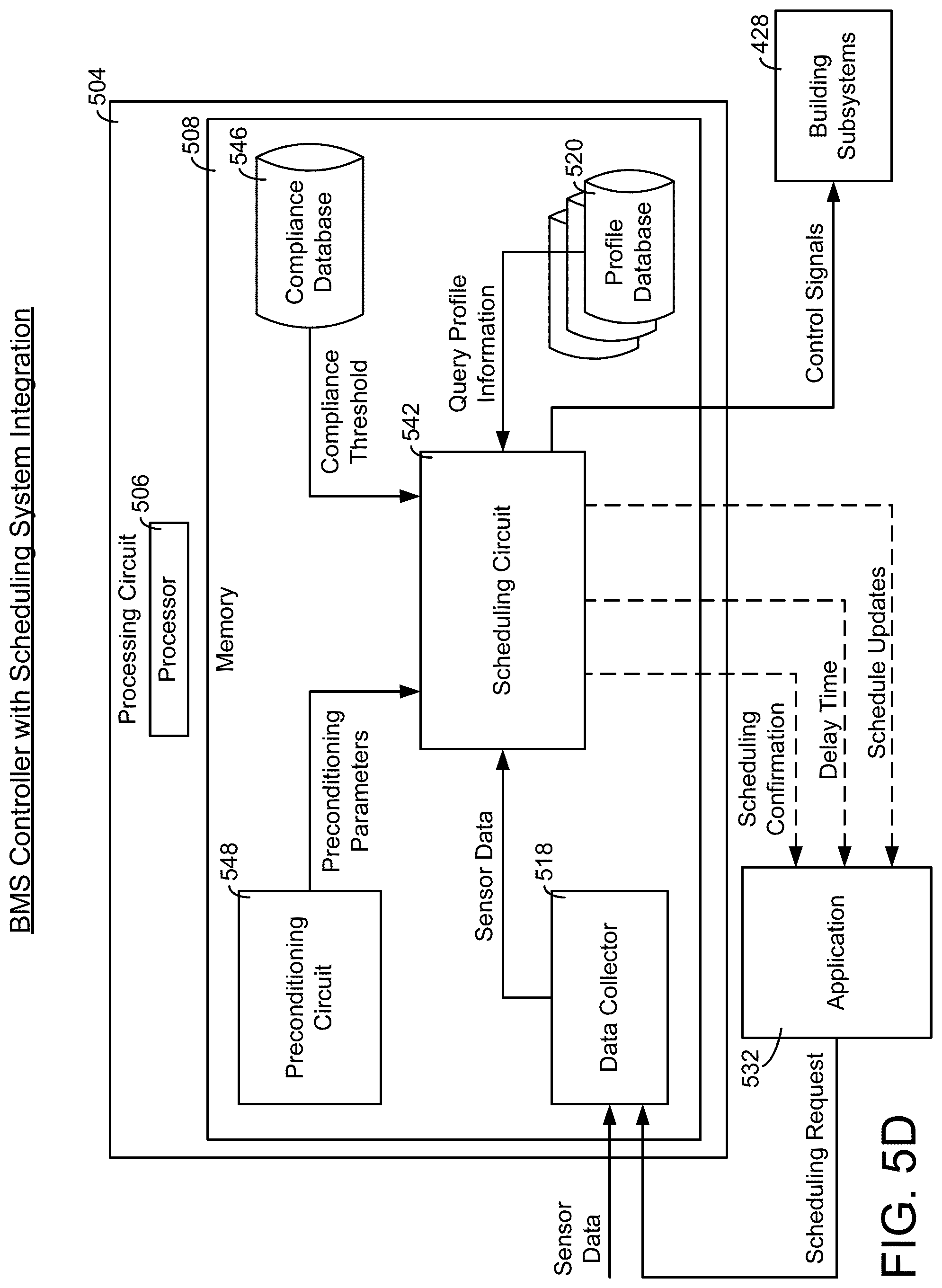
[0019] In another embodiment, a building management system (BMS) for heating, ventilation, or air conditioning (HVAC) parameters in a building includes one or more processing circuits comprising one or more memory devices coupled to one or more processors, the one or more memory devices configured to store instructions thereon. When executed by the one or more processors, the instructions cause the one or more processors to: receive temperature, pressure, and humidity (TPH) sensor data from one or more sensors, receive a scheduling request for a building room via an application dashboard, the scheduling request including a reservation time, a reservation date, and requested TPH setpoints, receive a work order including a fault code affecting the availability of the building room, determine if the building room is unavailable based on the work order, determine a required time to achieve the requested TPH setpoints based on the scheduling request and the work order, provide the required time and a scheduling confirmation to the application dashboard, and adjust HVAC equipment in the building to achieve the TPH setpoints prior to the reservation date and time.
[0020] In some embodiments, determining a required time to adjust the requested TPH setpoints includes determining a set of preconditioning parameters to be implemented in the building room prior to the reservation date and time and determining the required time based on at least one of a time for preconditioning parameters to be performed and a time for TPH levels to adjust to the TPH setpoints.
[0021] In some embodiments, the preconditioning parameters include at least one of an ultra-violet (UV) soak system, a fumigation system, a sanitization system, an air removal system, and an air filtration system.
[0022] In some embodiments, the application dashboard includes a scheduling interface configured to receive the required time and the scheduling confirmation, adjust the required time to achieve the requested TPH setpoints, update at least one of the reservation time, the reservation date, and the request for the building room, and adjust the preconditioning parameters implemented.
[0023] In some embodiments, the one or more memory devices store instructions thereon that, when executed by the one or more processors, cause the one or more processors to determine that the required time to achieve the requested TPH setpoints prior to the reservation date and time creates a scheduling conflict within the BMS, update the application dashboard based on the scheduling conflict, and provide the application dashboard with at least one of a new reservation time and a new reservation date such that the HVAC equipment can be adjusted prior to the reservation date and time.
[0024] In some embodiments, the user is one of a chief compliance officer, a facilities manager, an operating room administrator, a health care professional or a facilities technician.
[0025] In some embodiments, the one or more memory devices store instructions thereon that, when executed by the one or more processors, cause the one or more processors to receive an indication that the work order has been completed and updating the user interface to indicate that the work order has been completed.
[0026] In some embodiments, generating the work order includes generating a set of data including the fault and at least one of the corrective action, a time of the fault, and a location of the fault.
[0027] In some embodiments, the one or more memory devices store instructions thereon that, when executed by the one or more processors, cause the one or more processors to provide assistance functionality to the user interface, receive a request for assistance from the user interface via the assistance functionality, and provide additional information related to the corrective action to the user interface.
[0028] In some embodiments, the one or more memory devices store instructions thereon that, when executed by the one or more processors, cause the one or more processors to provide an alert in the building in response to determining the fault, wherein the alert includes at least one of a visual alert, an audible alert, a fault indication, and corrective action indication.
[0029] In some embodiments, the first dashboard or the second dashboard or both are configured to operate within a heads up display (HUD), and provide a list of inventory parts currently available for addressing the work order.
[0030] In some embodiments, the first dashboard or the second dashboard or both are configured to display regulations and codes related to TPH compliance, display information related to an interrelation of TPH of one or more building zones in the building, and display the TPH sensor data and the work order at least in part with color-coded formatting to indicate an intensity of the work order.
[0031] In some embodiments, the first dashboard or the second dashboard or both includes at least one of an audio interface, a visual interface, a touch screen interface, and a holographic interface, and a visual indicator proximate to the first dashboard or the second dashboard or both configured to indicate a compliance level of the TPH sensor data.
BRIEF DESCRIPTION OF THE DRAWINGS
[0032] FIG. 1 is a drawing of a building with a heating, ventilation, or air conditioning (HVAC) system, according to some embodiments.
[0033] FIG. 2 is a schematic of a waterside system which can be used as part of the HVAC system of FIG. 1, according to some embodiments,
[0034] FIG. 3 is a diagram of an airside system, which can be used as part of the HVAC system of FIG. 1, according to some embodiments.
[0035] FIG. 4 is a block diagram of a building management system (BMS) which can be used in the building of FIG. 1, according to some embodiments.
[0036] FIG. 5A is a diagram of a BMS for optimizing building conditions based on user input, which can be used in the building of FIG. 1, according to some embodiments.
[0037] FIG. 5B is a diagram of a BMS for providing work orders to an application which can be performed by the controller of FIG. 5A, according to some embodiments.
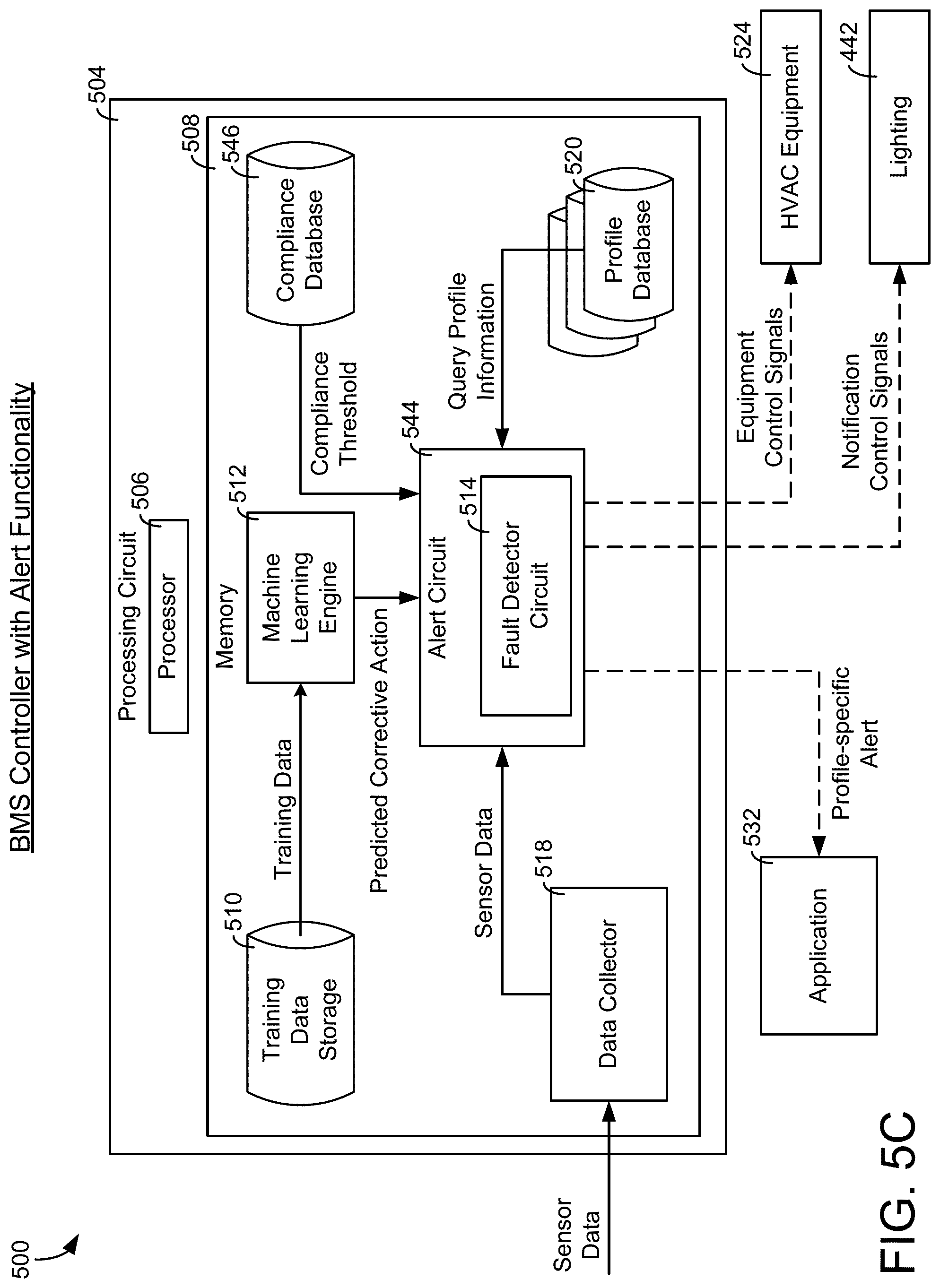
[0038] FIG. 5C is a diagram of a BMS with alert functionality which can be performed by the controller of FIG. 5A, according to some embodiments.
[0039] FIG. 5D is a diagram of a BMS with scheduling system integration which can be performed by the controller of FIG. 5A, according to some embodiments.
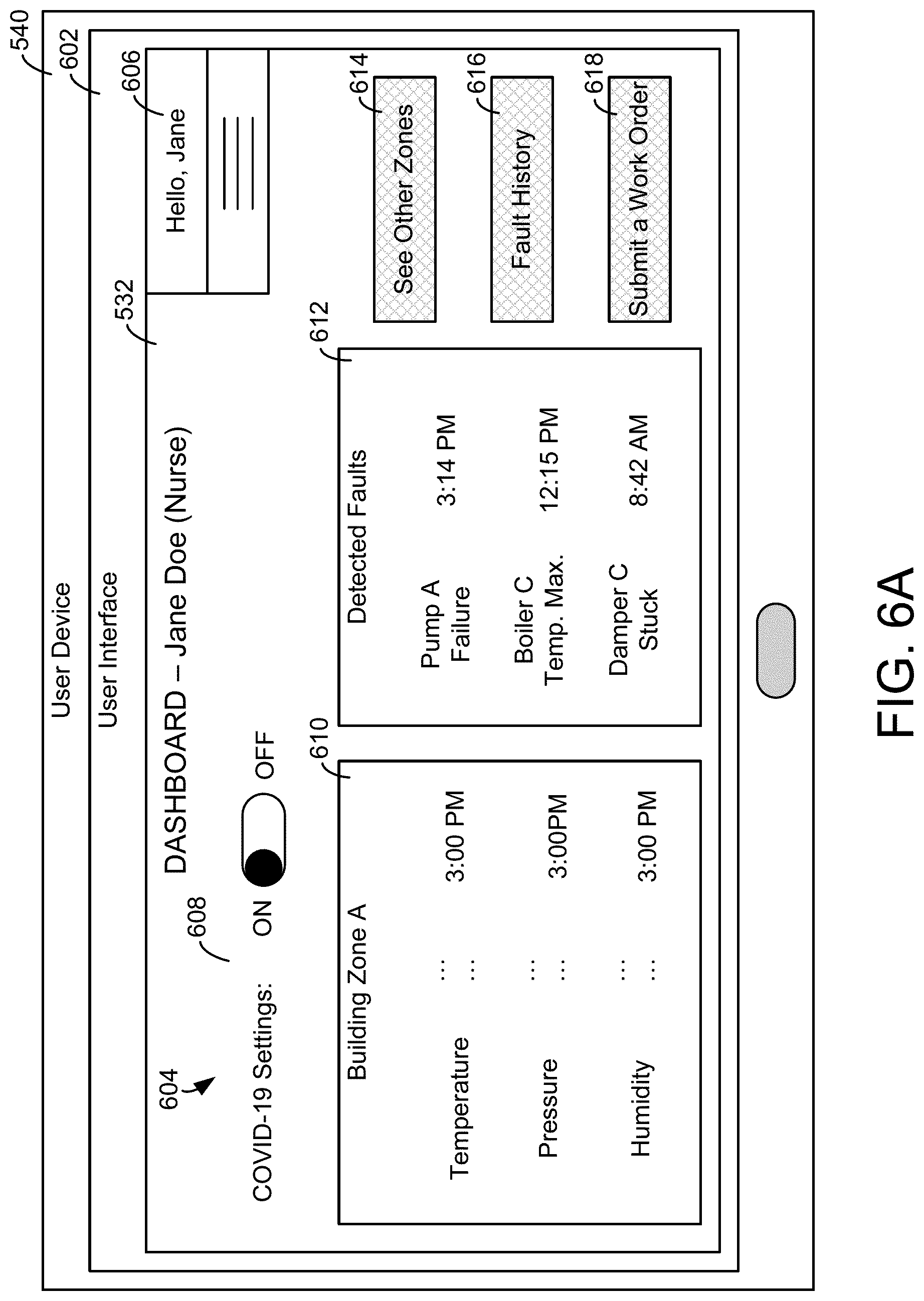
[0040] FIG. 6A is a diagram of an application on a user interface, which can be generated by the server of FIG. 5A, according to some embodiments.
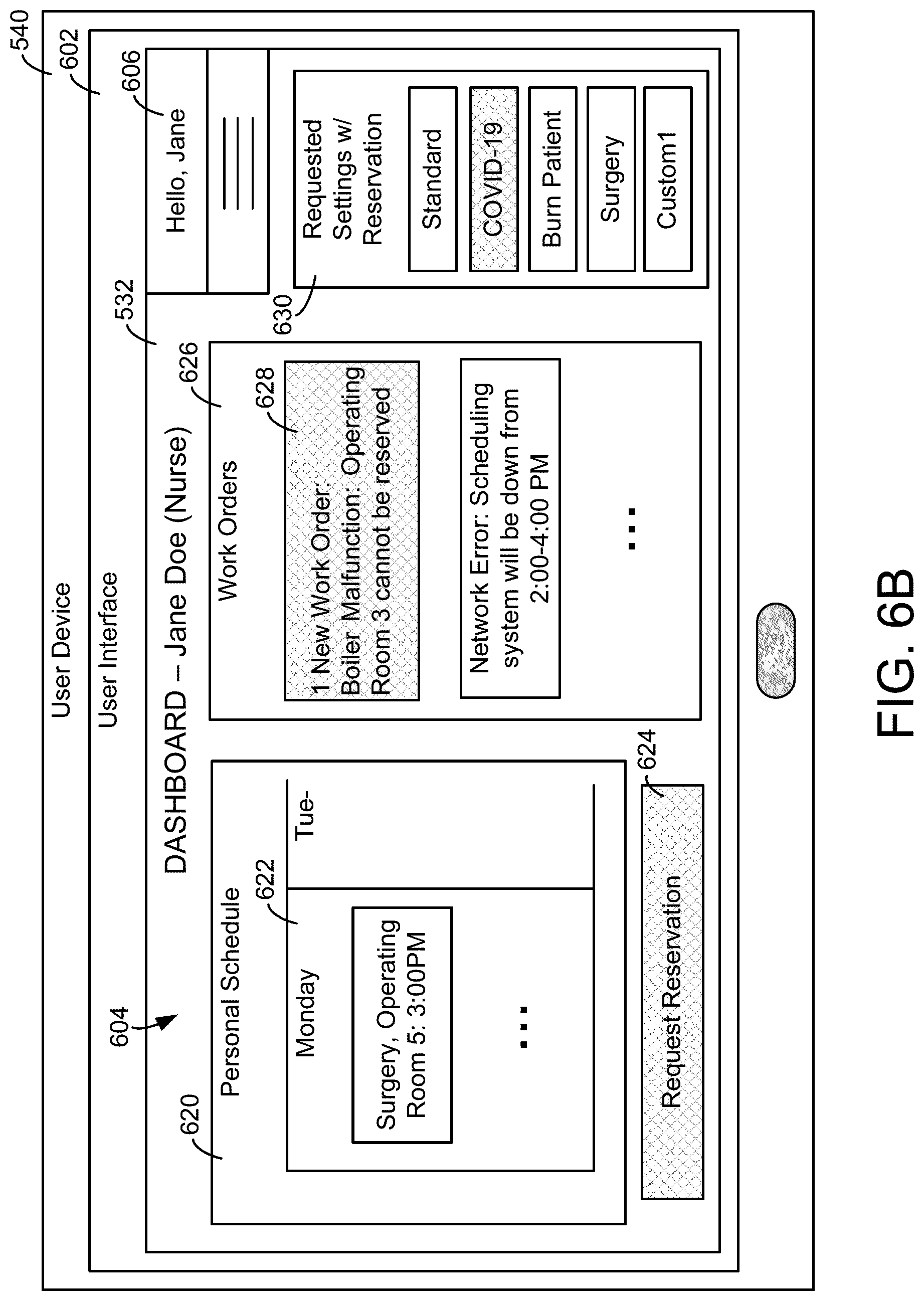
[0041] FIG. 6B is a diagram of an application on a user interface, which can be generated by the server of FIG. 5A, according to some embodiments.
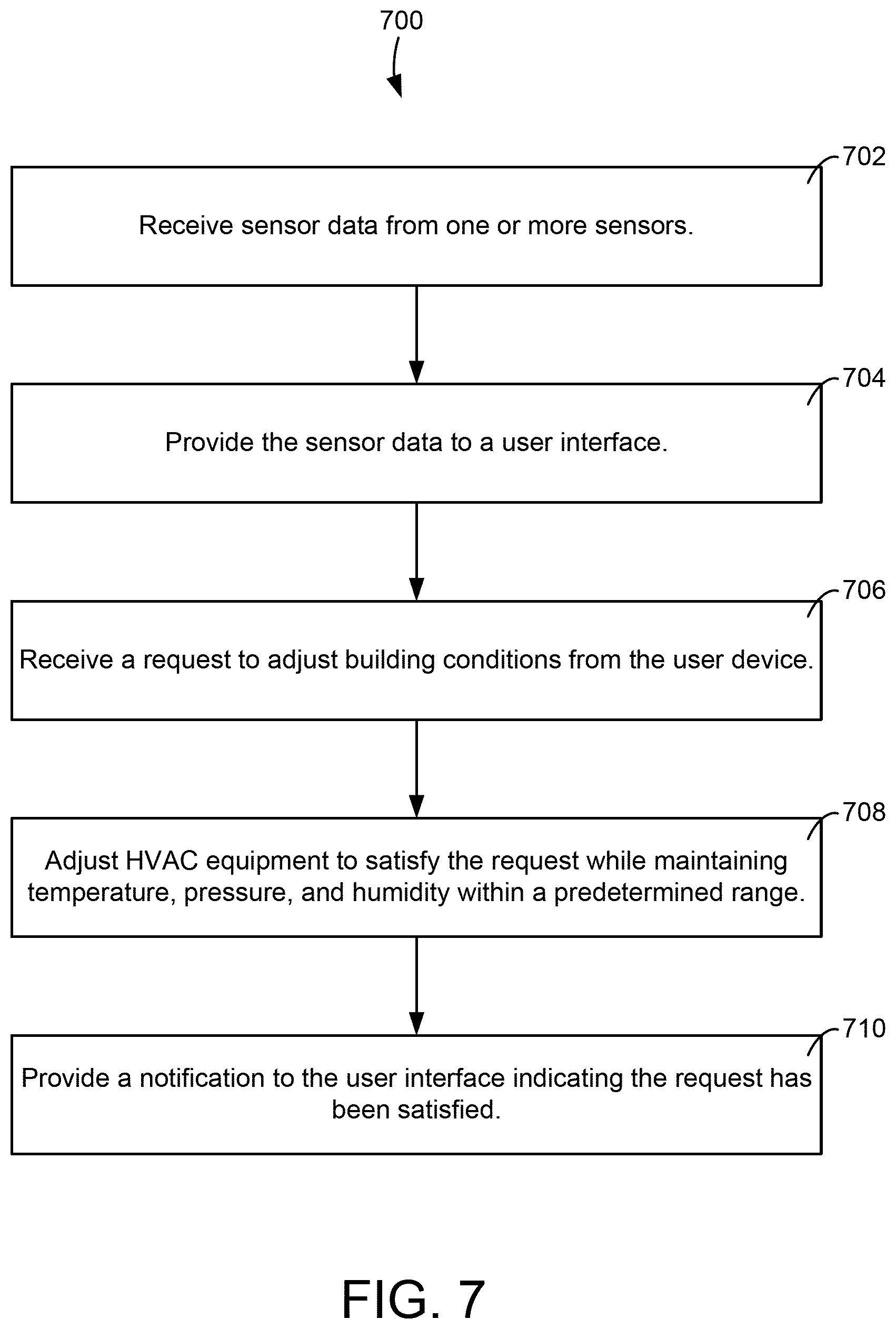
[0042] FIG. 7 is a flow diagram of a process for optimizing building conditions based on user input, which can be performed by the BMS controller of FIG. 5A, according to some embodiments.
[0043] FIG. 8 is a flow diagram of a process for predicting solutions to issues in an HVAC system, which can be performed by the BMS controller of FIG. 5A, according to some embodiments.
[0044] FIG. 9 is a flow diagram of a process optimizing control decisions for HVAC control in a building based on machine learning, which can be performed by the BMS controller of FIG. 5A, according to some embodiments.
[0045] FIG. 10 is a flow diagram of a process for determining fault causes in a BMS, which can be performed by the BMS controller of FIG. 5A, according to some embodiments.
[0046] FIG. 11 is a flow diagram of a process for operating an HVAC system based on scheduling requests, which can be performed by the BMS controller of FIG. 5A, according to some embodiments.
DETAILED DESCRIPTION
Overview
[0047] Before turning to the FIGURES, which illustrate certain exemplary embodiments in detail, it should be understood that the present disclosure is not limited to the details or methodology set forth in the description or illustrated in the FIGURES. It should also be understood that the terminology used herein is for the purpose of description only and should not be regarded as limiting.
[0048] Referring generally to the FIGURES, systems and methods are disclosed that improve comfortability for building occupants while maintaining appropriate levels of temperature, pressure, and humidity. In some embodiments, hospitals and/or clinics may need to conform to certain design criteria (e.g., American Society of Heating, Refrigerating and Air-Conditioning Engineers (ASHRAE) standard 170-2017, etc.) with regards to their HVAC systems to minimize infection, maintain staff comfort and contribute to an environment of patient care. These design criteria may require one or more building zones of the hospital or clinic to maintain temperature, pressure, and humidity (TPH) within a certain range or ranges. There exists a need to maintain TPH within these ranges while simultaneous providing comfortability to the building occupants, energy efficiency, and optimization in the HVAC system.
ASHRAE Standards Overview
[0049] Rooms in hospitals may require special design considerations due to intensified infection concerns (e.g., the spread of a contagious disease, etc.), high air change rates, special equipment, unique procedures, high internal loads and the presence of immunocompromised patients. However, these special considerations may be particularly important for hospital operating rooms (ORs), where their purpose is to minimize infection, maintain staff comfort and contribute to an environment of patient care.
[0050] In some embodiments, ANSI/ASHRAE/ASHE Standard 170, Ventilation of Health Care Facilities, is considered a critical standard of heating, ventilation, and air conditioning (HVAC) health-care ventilation design. The intent of the standard may be to provide comprehensive guidance, including a set of minimum requirements that define ventilation system design that helps provide environmental control for comfort, asepsis, and odor in health-care facilities. In some embodiments, it is adopted by code-enforcing agencies.
[0051] The standard may define minimum design requirements only, and due to the wide diversity of patient population and variations in their vulnerability and sensitivity, these standards may not guarantee an OR environment that will sufficiently provide comfort and control of airborne contagions and other elements of concern. When selecting the temperature and relative humidity combination to be incorporated into the design, these standard minimums and the desires of the surgical staff may need to be taken into consideration. In some embodiments, the ASHRAE HVAC Design Manual for Hospitals and Clinics discloses the inability to maintain low OR temperature as the primary complaint by surgeons to facility engineers.
Building Management System and HVAC System
Building Site
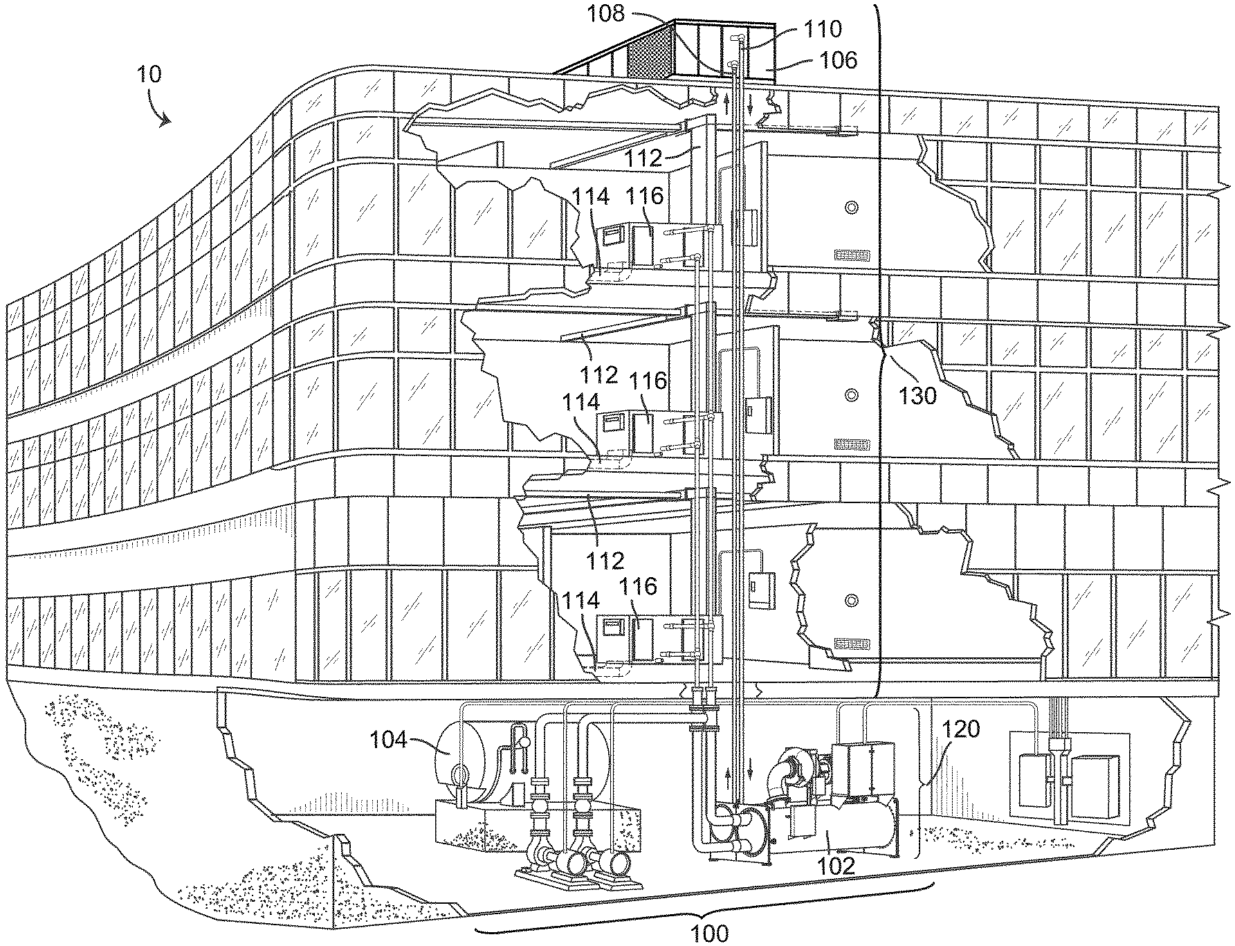
[0052] Referring now to FIG. 1, a perspective view of a building 10 is shown. Building 10 is served by a building management system (BMS). A BMS is, in general, a system of devices configured to control, monitor, and manage equipment in or around a building or building area. A BMS can include, for example, a HVAC system, a security system, a lighting system, a fire alerting system, any other system that is capable of managing building functions or devices, or any combination thereof.
[0053] The BMS that serves building 10 includes a HVAC system 100. HVAC system 100 may include a plurality of HVAC devices (e.g., heaters, chillers, air handling units, pumps, fans, thermal energy storage, etc.) configured to provide heating, cooling, ventilation, or other services for building 10. For example, HVAC system 100 includes a waterside system 120 and an airside system 130. Waterside system 120 may provide a heated or chilled fluid to an air handling unit of airside system 130. Airside system 130 may use the heated or chilled fluid to heat or cool an airflow provided to building 10. In some embodiments, waterside system 120 is replaced with a central energy plant such as central plant 200, described with reference to FIG. 2.
[0054] Still referring to FIG. 1, HVAC system 100 includes a chiller 102, a boiler 104, and a rooftop air handling unit (AHU) 106. Waterside system 120 may use boiler 104 and chiller 102 to heat or cool a working fluid (e.g., water, glycol, etc.) and may circulate the working fluid to AHU 106. In embodiments, the HVAC devices of waterside system 120 may be located in or around building 10 (as shown in FIG. 1) or at an offsite location such as a central plant (e.g., a chiller plant, a steam plant, a heat plant, etc.). The working fluid may be heated in boiler 104 or cooled in chiller 102, depending on whether heating or cooling is required in building 10. Boiler 104 may add heat to the circulated fluid, for example, by burning a combustible material (e.g., natural gas) or using an electric heating element. Chiller 102 may place the circulated fluid in a heat exchange relationship with another fluid (e.g., a refrigerant) in a heat exchanger (e.g., an evaporator) to absorb heat from the circulated fluid. The working fluid from chiller 102 and/or boiler 104 may be transported to AHU 106 via piping 108.
[0055] AHU 106 may place the working fluid in a heat exchange relationship with an airflow passing through AHU 106 (e.g., via one or more stages of cooling coils and/or heating coils). The airflow may be, for example, outside air, return air from within building 10, or a combination of both. AHU 106 may transfer heat between the airflow and the working fluid to provide heating or cooling for the airflow. For example, AHU 106 may include one or more fans or blowers configured to pass the airflow over or through a heat exchanger containing the working fluid. The working fluid may then return to chiller 102 or boiler 104 via piping 110.
[0056] Airside system 130 may deliver the airflow supplied by AHU 106 (i.e., the supply airflow) to building 10 via air supply ducts 112 and may provide return air from building 10 to AHU 106 via air return ducts 114. In some embodiments, airside system 130 includes multiple variable air volume (VAV) units 116. For example, airside system 130 includes a separate VAV unit 116 on each floor or zone of building 10. VAV units 116 may include dampers or other flow control elements that can be operated to control an amount of the supply airflow provided to individual zones of building 10. In other embodiments, airside system 130 delivers the supply airflow into one or more zones of building 10 (e.g., via air supply ducts 112) without using intermediate VAV units 116 or other flow control elements. AHU 106 may include sensors (e.g., temperature sensors, pressure sensors, etc.) configured to measure attributes of the supply airflow. AHU 106 may receive input from sensors located within AHU 106 and/or within the building zone and may adjust the flow rate, temperature, or other attributes of the supply airflow through AHU 106 to achieve setpoint conditions for the building zone.
Waterside System
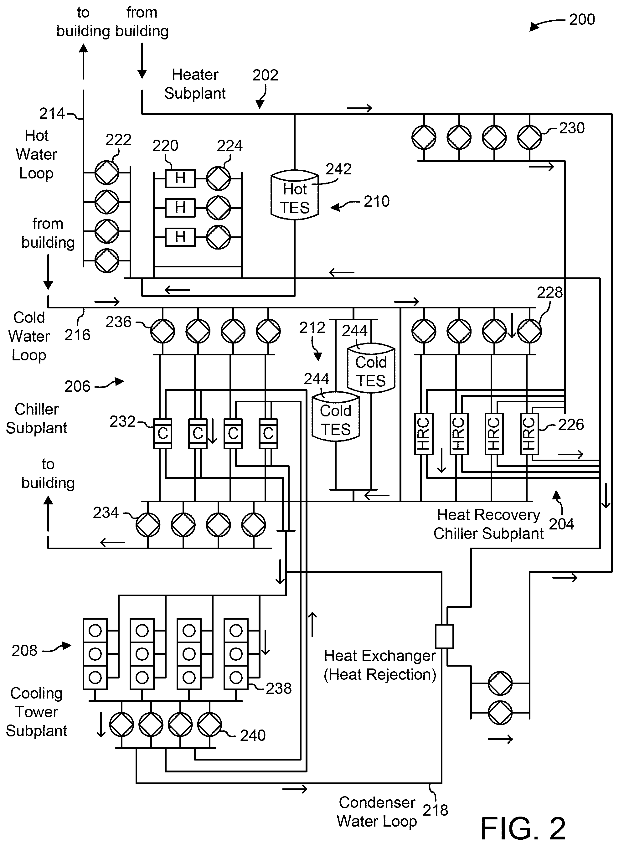
[0057] Referring now to FIG. 2, a block diagram of a central plant 200 is shown, according to an exemplary embodiment. In brief overview, central plant 200 may include types of equipment configured to serve the thermal energy loads of a building or campus (i.e., a system of buildings). For example, central plant 200 may include heaters, chillers, heat recovery chillers, cooling towers, or other types of equipment configured to serve the heating and/or cooling loads of a building or campus. Central plant 200 may consume resources from a utility (e.g., electricity, water, natural gas, etc.) to heat or cool a working fluid that is circulated to one or more buildings or stored for later use (e.g., in thermal energy storage tanks) to provide heating or cooling for the buildings. In embodiments, central plant 200 may supplement or replace waterside system 120 in building 10 or may be implemented separate from building 10 (e.g., at an offsite location).
[0058] Central plant 200 includes a plurality of subplants 202-212 including a heater subplant 202, a heat recovery chiller subplant 204, a chiller subplant 206, a cooling tower subplant 208, a hot thermal energy storage (TES) subplant 210, and a cold thermal energy storage (TES) subplant 212. Subplants 202-212 consume resources from utilities to serve the thermal energy loads (e.g., hot water, cold water, heating, cooling, etc.) of a building or campus. For example, heater subplant 202 may be configured to heat water in a hot water loop 214 that circulates the hot water between heater subplant 202 and building 10. Chiller subplant 206 may be configured to chill water in a cold water loop 216 that circulates the cold water between chiller subplant 206 and building 10. Heat recovery chiller subplant 204 may be configured to transfer heat from cold water loop 216 to hot water loop 214 to provide additional heating for the hot water and additional cooling for the cold water. Condenser water loop 218 may absorb heat from the cold water in chiller subplant 206 and reject the absorbed heat in cooling tower subplant 208 or transfer the absorbed heat to hot water loop 214. Hot TES subplant 210 and cold TES subplant 212 may store hot and cold thermal energy, respectively, for subsequent use.
[0059] Hot water loop 214 and cold water loop 216 may deliver the heated and/or chilled water to air handlers located on the rooftop of building 10 (e.g., AHU 106) or to individual floors or zones of building 10 (e.g., VAV units 116). The air handlers push air past heat exchangers (e.g., heating coils or cooling coils) through which the water flows to provide heating or cooling for the air. The heated or cooled air may be delivered to individual zones of building 10 to serve the thermal energy loads of building 10. The water then returns to subplants 202-212 to receive further heating or cooling.
[0060] Although subplants 202-212 are shown and described as heating and cooling water for circulation to a building, it is understood that any other type of working fluid (e.g., glycol, CO.sub.2, etc.) may be used in place of or in addition to water to serve the thermal energy loads. In other embodiments, subplants 202-212 may provide heating and/or cooling directly to the building or campus without requiring an intermediate heat transfer fluid. These and other variations to central plant 200 are within the teachings of the present invention.
[0061] Each of subplants 202-212 may include a variety of equipment configured to facilitate the functions of the subplant. For example, heater subplant 202 includes a plurality of heating elements 220 (e.g., boilers, electric heaters, etc.) configured to add heat to the hot water in hot water loop 214. Heater subplant 202 is also shown to include several pumps 222 and 224 configured to circulate the hot water in hot water loop 214 and to control the flow rate of the hot water through individual heating elements 220. Chiller subplant 206 includes a plurality of chillers 232 configured to remove heat from the cold water in cold water loop 216. Chiller subplant 206 is also shown to include several pumps 234 and 236 configured to circulate the cold water in cold water loop 216 and to control the flow rate of the cold water through individual chillers 232.
[0062] Heat recovery chiller subplant 204 includes a plurality of heat recovery heat exchangers 226 (e.g., refrigeration circuits) configured to transfer heat from cold water loop 216 to hot water loop 214. Heat recovery chiller subplant 204 is also shown to include several pumps 228 and 230 configured to circulate the hot water and/or cold water through heat recovery heat exchangers 226 and to control the flow rate of the water through individual heat recovery heat exchangers 226. Cooling tower subplant 208 includes a plurality of cooling towers 238 configured to remove heat from the condenser water in condenser water loop 218. Cooling tower subplant 208 is also shown to include several pumps 240 configured to circulate the condenser water in condenser water loop 218 and to control the flow rate of the condenser water through individual cooling towers 238.
[0063] Hot TES subplant 210 includes a hot TES tank 242 configured to store the hot water for later use. Hot TES subplant 210 may also include one or more pumps or valves configured to control the flow rate of the hot water into or out of hot TES tank 242. Cold TES subplant 212 includes cold TES tanks 244 configured to store the cold water for later use. Cold TES subplant 212 may also include one or more pumps or valves configured to control the flow rate of the cold water into or out of cold TES tanks 244.
[0064] In some embodiments, one or more of the pumps in central plant 200 (e.g., pumps 222, 224, 228, 230, 234, 236, and/or 240) or pipelines in central plant 200 include an isolation valve associated therewith. Isolation valves may be integrated with the pumps or positioned upstream or downstream of the pumps to control the fluid flows in central plant 200. In embodiments, central plant 200 may include more, fewer, or different types of devices and/or subplants based on the particular configuration of central plant 200 and the types of loads served by central plant 200.
Airside System
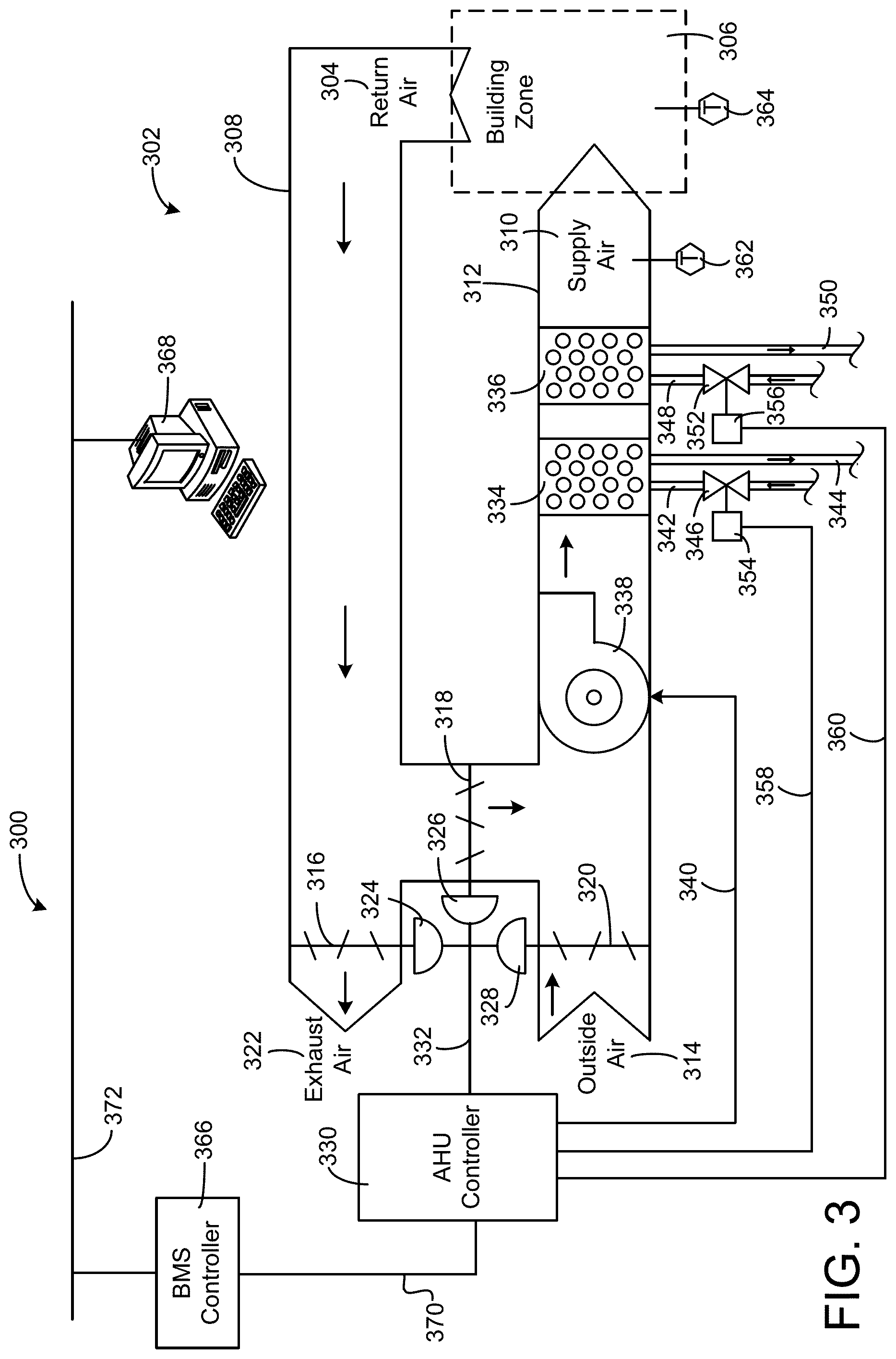
[0065] Referring now to FIG. 3, a block diagram of an airside system 300 is shown, according to an example embodiment. In embodiments, airside system 300 can supplement or replace airside system 130 in HVAC system 100 or can be implemented separate from HVAC system 100. When implemented in HVAC system 100, airside system 300 can include a subset of the HVAC devices in HVAC system 100 (e.g., AHU 106, VAV units 116, duct 112, duct 114, fans, dampers, etc.) and can be located in or around building 10. Airside system 300 can operate to heat or cool an airflow provided to building 10 using a heated or chilled fluid provided by waterside system 200.
[0066] In FIG. 3, airside system 300 includes an economizer-type air handling unit (AHU) 302. Economizer-type AHUs vary the amount of outside air and return air used by the air handling unit for heating or cooling. For example, AHU 302 can receive return air 304 from building zone 306 via return air duct 308 and can deliver supply air 310 to building zone 306 via supply air duct 312. In some embodiments, AHU 302 is a rooftop unit located on the roof of building 10 (e.g., AHU 106 as shown in FIG. 1) or otherwise positioned to receive both return air 304 and outside air 314. AHU 302 can be configured to operate exhaust air damper 316, mixing damper 318, and outside air damper 320 to control an amount of outside air 314 and return air 304 that combine to form supply air 310. Any return air 304 that does not pass through mixing damper 318 can be exhausted from AHU 302 through exhaust damper 316 as exhaust air 322.
[0067] Each of dampers 316-320 can be operated by an actuator. For example, exhaust air damper 316 can be operated by actuator 324, mixing damper 318 can be operated by actuator 326, and outside air damper 320 can be operated by actuator 328. Actuators 324-328 can communicate with an AHU controller 330 via a communications link 332. Actuators 324-328 can receive control signals from AHU controller 330 and can provide feedback signals to AHU controller 330. Feedback signals can include, for example, an indication of a current actuator or damper position, an amount of torque or force exerted by the actuator, diagnostic information (e.g., results of diagnostic tests performed by actuators 324-328), status information, commissioning information, configuration settings, calibration data, and/or other types of information or data that can be collected, stored, or used by actuators 324-328. AHU controller 330 can be an economizer controller configured to use one or more control algorithms (e.g., state-based algorithms, extremum seeking control (ESC) algorithms, proportional-integral (PI) control algorithms, proportional-integral-derivative (PID) control algorithms, model predictive control (MPC) algorithms, feedback control algorithms, etc.) to control actuators 324-328.
[0068] Still referring to FIG. 3, AHU 302 includes a cooling coil 334, a heating coil 336, and a fan 338 positioned within supply air duct 312. Fan 338 can be configured to force supply air 310 through cooling coil 334 and/or heating coil 336 and provide supply air 310 to building zone 306. AHU controller 330 can communicate with fan 338 via communications link 340 to control a flow rate of supply air 310. In some embodiments, AHU controller 330 controls an amount of heating or cooling applied to supply air 310 by modulating a speed of fan 338.
[0069] Cooling coil 334 can receive a chilled fluid from waterside system 200 (e.g., from cold water loop 216) via piping 342 and can return the chilled fluid to waterside system 200 via piping 344. Valve 346 can be positioned along piping 342 or piping 344 to control a flow rate of the chilled fluid through cooling coil 334. In some embodiments, cooling coil 334 includes multiple stages of cooling coils that can be independently activated and deactivated (e.g., by AHU controller 330, by BMS controller 366, etc.) to modulate an amount of cooling applied to supply air 310.
[0070] Heating coil 336 can receive a heated fluid from waterside system 200 (e.g., from hot water loop 214) via piping 348 and can return the heated fluid to waterside system 200 via piping 350. Valve 352 can be positioned along piping 348 or piping 350 to control a flow rate of the heated fluid through heating coil 336. In some embodiments, heating coil 336 includes multiple stages of heating coils that can be independently activated and deactivated (e.g., by AHU controller 330, by BMS controller 366, etc.) to modulate an amount of heating applied to supply air 310.
[0071] Each of valves 346 and 352 can be controlled by an actuator. For example, valve 346 can be controlled by actuator 354 and valve 352 can be controlled by actuator 356. Actuators 354-356 can communicate with AHU controller 330 via communications links 358-360. Actuators 354-356 can receive control signals from AHU controller 330 and can provide feedback signals to controller 330. In some embodiments, AHU controller 330 receives a measurement of the supply air temperature from a temperature sensor 362 positioned in supply air duct 312 (e.g., downstream of cooling coil 334 and/or heating coil 336). AHU controller 330 can also receive a measurement of the temperature of building zone 306 from a temperature sensor 364 located in building zone 306.
[0072] In some embodiments, AHU controller 330 operates valves 346 and 352 via actuators 354-356 to modulate an amount of heating or cooling provided to supply air 310 (e.g., to achieve a setpoint temperature for supply air 310 or to maintain the temperature of supply air 310 within a setpoint temperature range). The positions of valves 346 and 352 affect the amount of heating or cooling provided to supply air 310 by cooling coil 334 or heating coil 336 and may correlate with the amount of energy consumed to achieve a desired supply air temperature. AHU controller 330 can control the temperature of supply air 310 and/or building zone 306 by activating or deactivating coils 334-336, adjusting a speed of fan 338, or a combination of both.
[0073] Still referring to FIG. 3, airside system 300 includes a building management system (BMS) controller 366 and a client device 368. BMS controller 366 can include one or more computer systems (e.g., servers, supervisory controllers, subsystem controllers, etc.) that serve as system level controllers, application or data servers, head nodes, or master controllers for airside system 300, waterside system 200, HVAC system 100, and/or other controllable systems that serve building 10. BMS controller 366 can communicate with multiple downstream building systems or subsystems (e.g., HVAC system 100, a security system, a lighting system, waterside system 200, etc.) via a communications link 370 according to like or disparate protocols (e.g., LON, BACnet, etc.). In embodiments, AHU controller 330 and BMS controller 366 can be separate (as shown in FIG. 3) or integrated. In an integrated implementation, AHU controller 330 can be a software module configured for execution by a processor of BMS controller 366.
[0074] In some embodiments, AHU controller 330 receives information from BMS controller 366 (e.g., commands, set points, operating boundaries, etc.) and provides information to BMS controller 366 (e.g., temperature measurements, valve or actuator positions, operating statuses, diagnostics, etc.). For example, AHU controller 330 can provide BMS controller 366 with temperature measurements from temperature sensors 362 and 364, equipment on/off states, equipment operating capacities, and/or any other information that can be used by BMS controller 366 to monitor or control a variable state or condition within building zone 306.
[0075] Client device 368 can include one or more human-machine interfaces or client interfaces (e.g., graphical user interfaces, reporting interfaces, text-based computer interfaces, client-facing web services, web servers that provide pages to web clients, etc.) for controlling, viewing, or otherwise interacting with HVAC system 100, its subsystems, and/or devices. Client device 368 can be a computer workstation, a client terminal, a remote or local interface, or any other type of user interface device. Client device 368 can be a stationary terminal or a mobile device. For example, client device 368 can be a desktop computer, a computer server with a user interface, a laptop computer, a tablet, a smartphone, a PDA, or any other type of mobile or non-mobile device. Client device 368 can communicate with BMS controller 366 and/or AHU controller 330 via communications link 372.
Building Management System
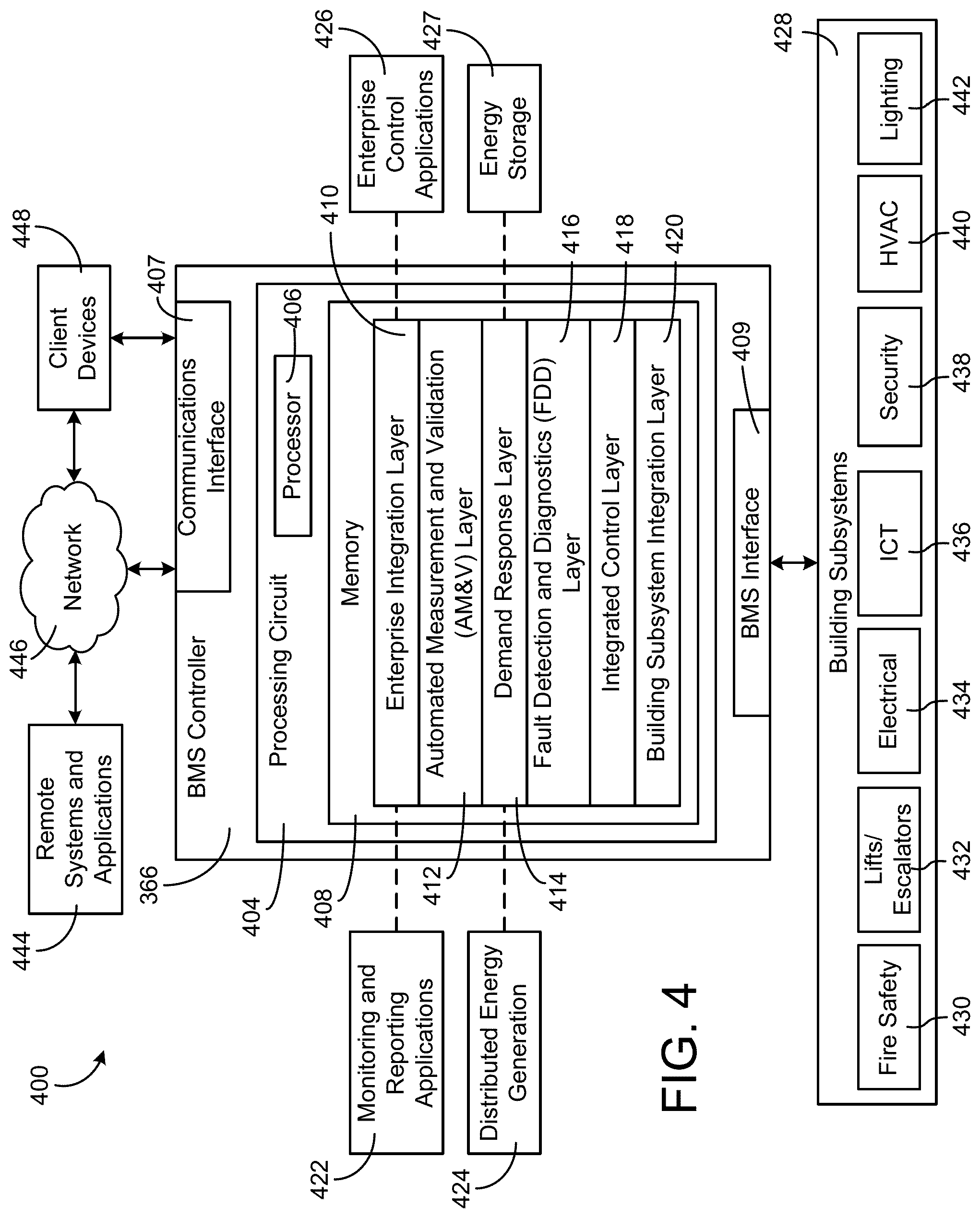
[0076] Referring now to FIG. 4, a block diagram of a building management system (BMS) 400 is shown, according to an example embodiment. BMS 400 can be implemented in building 10 to automatically monitor and control building functions. BMS 400 includes BMS controller 366 and a plurality of building subsystems 428. Building subsystems 428 are shown to include a building electrical subsystem 434, an information communication technology (ICT) subsystem 436, a security subsystem 438, a HVAC subsystem 440, a lighting subsystem 442, a lift/escalators subsystem 432, and a fire safety subsystem 430. In embodiments, building subsystems 428 can include fewer, additional, or alternative subsystems. For example, building subsystems 428 can also or alternatively include a refrigeration subsystem, an advertising or signage subsystem, a cooking subsystem, a vending subsystem, a printer or copy service subsystem, or any other type of building subsystem that uses controllable equipment and/or sensors to monitor or control building 10. In some embodiments, building subsystems 428 include waterside system 200 and/or airside system 300, as described with reference to FIGS. 2 and 3.
[0077] Each of building subsystems 428 can include any number of devices, controllers, and connections for completing its individual functions and control activities. HVAC subsystem 440 can include many of the same components as HVAC system 100, as described with reference to FIGS. 1-3. For example, HVAC subsystem 440 can include a chiller, a boiler, any number of air handling units, economizers, field controllers, supervisory controllers, actuators, temperature sensors, and other devices for controlling the temperature, humidity, airflow, or other variable conditions within building 10. Lighting subsystem 442 can include any number of light fixtures, ballasts, lighting sensors, dimmers, or other devices configured to controllably adjust the amount of light provided to a building space. Security subsystem 438 can include occupancy sensors, video surveillance cameras, digital video recorders, video processing servers, intrusion detection devices, access control devices (e.g., card access, etc.) and servers, or other security-related devices.
[0078] Still referring to FIG. 4, BMS controller 366 includes a communications interface 407 and a BMS interface 409. Interface 407 can facilitate communications between BMS controller 366 and external applications (e.g., monitoring and reporting applications 422, enterprise control applications 426, remote systems and applications 444, applications residing on client devices 448, etc.) for allowing user control, monitoring, and adjustment to BMS controller 366 and/or subsystems 428. Interface 407 can also facilitate communications between BMS controller 366 and client devices 448. BMS interface 409 can facilitate communications between BMS controller 366 and building subsystems 428 (e.g., HVAC, lighting security, lifts, power distribution, business, etc.).
[0079] Interfaces 407, 409 can be or include wired or wireless communications interfaces (e.g., jacks, antennas, transmitters, receivers, transceivers, wire terminals, etc.) for conducting data communications with building subsystems 428 or other external systems or devices. In embodiments, communications via interfaces 407, 409 can be direct (e.g., local wired or wireless communications) or via a communications network 446 (e.g., a WAN, the Internet, a cellular network, etc.). For example, interfaces 407, 409 can include an Ethernet card and port for sending and receiving data via an Ethernet-based communications link or network. In another example, interfaces 407, 409 can include a Wi-Fi transceiver for communicating via a wireless communications network. In another example, one or both of interfaces 407, 409 can include cellular or mobile phone communications transceivers. In one embodiment, communications interface 407 is a power line communications interface and BMS interface 409 is an Ethernet interface. In other embodiments, both communications interface 407 and BMS interface 409 are Ethernet interfaces or are the same Ethernet interface.
[0080] Still referring to FIG. 4, BMS controller 366 includes a processing circuit 404 including a processor 406 and memory 408. Processing circuit 404 can be communicably connected to BMS interface 409 and/or communications interface 407 such that processing circuit 404 and the components thereof can send and receive data via interfaces 407, 409. Processor 406 can be implemented as a general purpose processor, an application specific integrated circuit (ASIC), one or more field programmable gate arrays (FPGAs), a group of processing components, or other suitable electronic processing components.
[0081] Memory 408 (e.g., memory, memory unit, storage device, etc.) can include one or more devices (e.g., RAM, ROM, Flash memory, hard disk storage, etc.) for storing data and/or computer code for completing or facilitating the processes, layers and modules described in the present application. Memory 408 can be or include volatile memory or non-volatile memory. Memory 408 can include database components, object code components, script components, or any other type of information structure for supporting the activities and information structures described in the present application. According to an example embodiment, memory 408 is communicably connected to processor 406 via processing circuit 404 and includes computer code for executing (e.g., by processing circuit 404 and/or processor 406) one or more processes described herein.
[0082] In some embodiments, BMS controller 366 is implemented within a single computer (e.g., one server, one housing, etc.). In other embodiments BMS controller 366 can be distributed across multiple servers or computers (e.g., that can exist in distributed locations). Further, while FIG. 4 shows applications 422 and 426 as existing outside of BMS controller 366, in some embodiments, applications 422 and 426 can be hosted within BMS controller 366 (e.g., within memory 408).
[0083] Still referring to FIG. 4, memory 408 includes an enterprise integration layer 410, an automated measurement and validation (AM&V) layer 412, a demand response (DR) layer 414, a fault detection and diagnostics (FDD) layer 416, an integrated control layer 418, and a building subsystem integration later 420. Layers 410-420 can be configured to receive inputs from building subsystems 428 and other data sources, determine optimal control actions for building subsystems 428 based on the inputs, generate control signals based on the optimal control actions, and provide the generated control signals to building subsystems 428. The following paragraphs describe some of the general functions performed by each of layers 410-420 in BMS 400.
[0084] Enterprise integration layer 410 can be configured to serve clients or local applications with information and services to support a variety of enterprise-level applications. For example, enterprise control applications 426 can be configured to provide subsystem-spanning control to a graphical user interface (GUI) or to any number of enterprise-level business applications (e.g., accounting systems, user identification systems, etc.). Enterprise control applications 426 can also or alternatively be configured to provide configuration GUIs for configuring BMS controller 366. In yet other embodiments, enterprise control applications 426 can work with layers 410-420 to optimize building performance (e.g., efficiency, energy use, comfort, or safety) based on inputs received at interface 407 and/or BMS interface 409.
[0085] Building subsystem integration layer 420 can be configured to manage communications between BMS controller 366 and building subsystems 428. For example, building subsystem integration layer 420 can receive sensor data and input signals from building subsystems 428 and provide output data and control signals to building subsystems 428. Building subsystem integration layer 420 can also be configured to manage communications between building subsystems 428. Building subsystem integration layer 420 translate communications (e.g., sensor data, input signals, output signals, etc.) across a plurality of multi-vendor/multi-protocol systems.
[0086] Demand response layer 414 can be configured to optimize resource usage (e.g., electricity use, natural gas use, water use, etc.) and/or the monetary cost of such resource usage in response to satisfy the demand of building 10. The optimization can be based on time-of-use prices, curtailment signals, energy availability, or other data received from utility providers, distributed energy generation systems 424, from energy storage 427 (e.g., hot TES 242, cold TES 244, etc.), or from other sources. Demand response layer 414 can receive inputs from other layers of BMS controller 366 (e.g., building subsystem integration layer 420, integrated control layer 418, etc.). The inputs received from other layers can include environmental or sensor inputs such as temperature, carbon dioxide levels, relative humidity levels, air quality sensor outputs, occupancy sensor outputs, room schedules, and the like. The inputs can also include inputs such as electrical use (e.g., expressed in kWh), thermal load measurements, pricing information, projected pricing, smoothed pricing, curtailment signals from utilities, and the like.
[0087] According to an example embodiment, demand response layer 414 includes control logic for responding to the data and signals it receives. These responses can include communicating with the control algorithms in integrated control layer 418, changing control strategies, changing set points, or activating/deactivating building equipment or subsystems in a controlled manner. Demand response layer 414 can also include control logic configured to determine when to utilize stored energy. For example, demand response layer 414 can determine to begin using energy from energy storage 427 just prior to the beginning of a peak use hour.
[0088] In some embodiments, demand response layer 414 includes a control module configured to actively initiate control actions (e.g., automatically changing set points) which minimize energy costs based on one or more inputs representative of or based on demand (e.g., price, a curtailment signal, a demand level, etc.). In some embodiments, demand response layer 414 uses equipment models to determine an optimal set of control actions. The equipment models can include, for example, thermodynamic models describing the inputs, outputs, and/or functions performed by sets of building equipment. Equipment models can represent collections of building equipment (e.g., subplants, chiller arrays, etc.) or individual devices (e.g., individual chillers, heaters, pumps, etc.).
[0089] Demand response layer 414 can further include or draw upon one or more demand response policy definitions (e.g., databases, XML files, etc.). The policy definitions can be edited or adjusted by a user (e.g., via a graphical user interface) so that the control actions initiated in response to demand inputs can be tailored for the user's application, desired comfort level, particular building equipment, or based on other concerns. For example, the demand response policy definitions can specify which equipment can be turned on or off in response to particular demand inputs, how long a system or piece of equipment should be turned off, what set points can be changed, what the allowable set point adjustment range is, how long to hold a high demand setpoint before returning to a normally scheduled setpoint, how close to approach capacity limits, which equipment modes to utilize, the energy transfer rates (e.g., the maximum rate, an alarm rate, other rate boundary information, etc.) into and out of energy storage devices (e.g., thermal storage tanks, battery banks, etc.), and when to dispatch on-site generation of energy (e.g., via fuel cells, a motor generator set, etc.).
[0090] Integrated control layer 418 can be configured to use the data input or output of building subsystem integration layer 420 and/or demand response later 414 to make control decisions. Due to the subsystem integration provided by building subsystem integration layer 420, integrated control layer 418 can integrate control activities of the subsystems 428 such that the subsystems 428 behave as a single integrated supersystem. In an example embodiment, integrated control layer 418 includes control logic that uses inputs and outputs from a plurality of building subsystems to provide greater comfort and energy savings relative to the comfort and energy savings that separate subsystems could provide alone. For example, integrated control layer 418 can be configured to use an input from a first subsystem to make an energy-saving control decision for a second subsystem. Results of these decisions can be communicated back to building subsystem integration layer 420.
[0091] Integrated control layer 418 is shown to be logically below demand response layer 414. Integrated control layer 418 can be configured to enhance the effectiveness of demand response layer 414 by enabling building subsystems 428 and their respective control loops to be controlled in coordination with demand response layer 414. This configuration may advantageously reduce disruptive demand response behavior relative to conventional systems. For example, integrated control layer 418 can be configured to assure that a demand response-driven upward adjustment to the setpoint for chilled water temperature (or another component that directly or indirectly affects temperature) does not result in an increase in fan energy (or other energy used to cool a space) that would result in greater total building energy use than was saved at the chiller.
[0092] Integrated control layer 418 can be configured to provide feedback to demand response layer 414 so that demand response layer 414 checks that constraints (e.g., temperature, lighting levels, etc.) are properly maintained even while demanded load shedding is in progress. The constraints can also include setpoint or sensed boundaries relating to safety, equipment operating limits and performance, comfort, fire codes, electrical codes, energy codes, and the like. Integrated control layer 418 is also logically below fault detection and diagnostics layer 416 and automated measurement and validation layer 412. Integrated control layer 418 can be configured to provide calculated inputs (e.g., aggregations) to these higher levels based on outputs from more than one building subsystem.
[0093] Automated measurement and validation (AM&V) layer 412 can be configured to verify that control strategies commanded by integrated control layer 418 or demand response layer 414 are working properly (e.g., using data aggregated by AM&V layer 412, integrated control layer 418, building subsystem integration layer 420, FDD layer 416, or otherwise). The calculations made by AM&V layer 412 can be based on building system energy models and/or equipment models for individual BMS devices or subsystems. For example, AM&V layer 412 can compare a model-predicted output with an actual output from building subsystems 428 to determine an accuracy of the model.
[0094] Fault detection and diagnostics (FDD) layer 416 can be configured to provide on-going fault detection for building subsystems 428, building subsystem devices (i.e., building equipment), and control algorithms used by demand response layer 414 and integrated control layer 418. FDD layer 416 can receive data inputs from integrated control layer 418, directly from one or more building subsystems or devices, or from another data source. FDD layer 416 can automatically diagnose and respond to detected faults. The responses to detected or diagnosed faults can include providing an alert message to a user, a maintenance scheduling system, or a control algorithm configured to attempt to repair the fault or to work-around the fault.
[0095] FDD layer 416 can be configured to output a specific identification of the faulty component or cause of the fault (e.g., loose damper linkage) using detailed subsystem inputs available at building subsystem integration layer 420. In other example embodiments, FDD layer 416 is configured to provide "fault" events to integrated control layer 418 which executes control strategies and policies in response to the received fault events. According to an example embodiment, FDD layer 416 (or a policy executed by an integrated control engine or business rules engine) can shut-down systems or direct control activities around faulty devices or systems to reduce energy waste, extend equipment life, or assure proper control response.
[0096] FDD layer 416 can be configured to store or access a variety of different system data stores (or data points for live data). FDD layer 416 can use some content of the data stores to identify faults at the equipment level (e.g., specific chiller, specific AHU, specific terminal unit, etc.) and other content to identify faults at component or subsystem levels. For example, building subsystems 428 can generate temporal (i.e., time-series) data indicating the performance of BMS 400 and the components thereof. The data generated by building subsystems 428 can include measured or calculated values that exhibit statistical characteristics and provide information about how the corresponding system or process (e.g., a temperature control process, a flow control process, etc.) is performing in terms of error from its setpoint. These processes can be examined by FDD layer 416 to expose when the system begins to degrade in performance and alert a user to repair the fault before it becomes more severe.
Temperature, Pressure, and Humidity System
[0097] As shown in FIG. 5A, a system 500 for controlling TPH is structured to receive user input regarding HVAC systems (e.g., the waterside system 200, the airside system 300, the BMS system 400, etc.) within the building 10, and adjust control based on the user input. The system 500 may include any combination of aspects described herein. For example, the HVAC equipment 524, as described below, may include the pumps 234 and the fan 338, described reference to FIGS. 2 and 3 or other components, as desired. The system 500 includes a BMS controller 502, the HVAC equipment 524, a building zone 526, a network 530, an application 532, a server 534, and user devices 536-540.
[0098] In some embodiments, the BMS controller 502 may be similar to BMS controller 366 as described above with reference to FIG. 4. In some embodiments, BMS controller 502 incorporates additional features or functionality that allow for improved TPH control. The BMS controller 502 includes a processing circuit 504 communicably connected to a communications interface 522 so that the processing circuit 504 can send and receive data via the communications interface 522. The processing circuit 504 includes a processor 506 and a memory 508.
[0099] The processor 506 can be implemented as a general purpose processor, an application specific integrated circuit (ASIC), one or more field programmable gate arrays (FPGAs), a group of processing components, or other suitable electronic processing components. The memory 508 (e.g., memory, memory unit, storage device, etc.) can include one or more devices (e.g., RAM, ROM, Flash memory, hard disk storage, etc.) for storing data and/or computer code for completing or facilitating the processes, layers and modules described in the present application. Memory 508 can be or include volatile memory or non-volatile memory. The memory 508 can include database components, object code components, script components, or any other type of information structure for supporting the activities and information structures described in the present application. According to an example embodiment, the memory 508 is communicably connected to the processor 506 via the processing circuit 504 and includes computer code for executing (e.g., by the processing circuit 504 and/or the processor 506) one or more processes described herein.
[0100] In some embodiments, the BMS controller 502 is implemented within a single computer (e.g., one server, one housing, etc.). In some embodiments, the BMS controller 502 is distributed across multiple servers or computers (e.g., that can exist in geographically separated locations). The memory 508 includes a training data storage 510, a machine learning engine 512, a fault detector circuit 514, a work order circuit 516, a data collector 518, and a profile database 520. While the systems and methods disclosed herein generally refer to building control within hospitals and clinics, other types of buildings, campuses, and floorplans may implement the systems and methods disclosed herein, including data centers, fish hatcheries, pharmaceutical labs, and office buildings. Additionally, while the BMS controller 502 is shown to handle processing related to collecting data, storing profile databases, artificial intelligence, etc., some or all of this functionality may be performed in a distributed group of processors, memories, etc., or within cloud processed applications (e.g., the application 532).
[0101] The training data storage 510 may be configured to store data used for training one or more machine learning components within the system 500. For example, the training data storage 510 is shown providing training data to the machine learning engine 512. In some embodiments, training data includes previous fault data related to the system 500 allowing the machine learning engine 512 to develop intelligence that predicts solutions to faults in HVAC systems. For example, the training data storage 510 may include hundreds of previous faults (e.g., stuck dampers, failed pumps, overheating boilers, stuck valves, incorrect installations, etc.) from HVAC equipment 524. In some embodiments, the training data storage 510 includes a remote database that can be queried by the BMS controller 502 to receive the training data or a portion of the training data. In some embodiments, the training data storage 510 is located locally within the BMS 502 and stores a local set of training data.
[0102] The machine learning engine 512 is structured to receive the training data from the training data storage 510 and determine trends in which solutions were implemented for correlated faults. For example, restarting a controller/actuator assembly in response to a stuck damper fault. Upon developing the intelligence for predicting solutions for particular faults, the BMS controller 502 may then be able to provide the application 532 with a recommended solution to a fault. The fault solution functionality described herein may be similar to fault prediction systems and methods described in U.S. Patent Publication Application No. 2019/0041882 filed Aug. 3, 2017, the entire disclosure of which is incorporated by reference herein.
[0103] In some embodiments, the training data includes previous fault data related to the system 500 such that the machine learning engine 512 can develop intelligence for predicting solutions to work orders in HVAC systems. Work orders may be submitted via one or more building occupants (these and other information and/or requests are submitted via the application 532, which is described in greater detail below) or generated automatically either locally by a component that recognizes service is required, a central service prediction system, a fault detection system, or other automated systems. The work orders may include standard equipment updates such as "Pump A requires an oil change" or "Calibrate Actuator C." However, the work orders may also include specific requests from building occupants. For example, a nurse on a hospital floor may send a request from their user device 536 via the application 532 to replace a lightbulb in a patient room. The BMS controller 502 may receive the user request via the network 530 and provide a recommended solution for the work order to a technician. The solution may be based on one or more previously filed work orders that may be similar to the current work order. In the above example, this solution may be "Replace single light bulb in Room A5--GE U-Bend Fluorescent Bulb (T8/Medium)." The inclusion of the recommended solution within the work order facilitates a quicker completion time of the work orders.
[0104] In some embodiments, the machine learning engine 512 utilizes decision trees, generated models via a model predictive architecture, trend analyses, neural networks, deep neural networks, reinforcement learning, and other machine learning and artificial intelligence schemes that improve over time and improve predictions of the BMS controller 502. No matter the specific implementation of the machine learning engine 512, the training data is utilized to develop a machine learning scheme structured to receive inputs in the form of faults or work requests, and provide a recommended solution. As described herein, users may refer to facility managers, technicians, nurse managers, compliance officers, nurses, doctors, and other building occupants.
[0105] The fault detector circuit 514 is structured to determine that a fault has occurred in a system of component. In some embodiments, the fault is a sensed failure of a system or component, a manually entered fault of a system or component, or a user request (e.g., the lightbulb example described above). The fault detector circuit 514 is structured to provide the fault to the machine learning engine 512, and to receive a recommended solution from the machine learning engine 512. The fault detector circuit 514 then sends the fault and the recommended solution to the work order circuit 516. For example, the fault detector circuit 514 may send the fault and recommended solution to the interface of a user device 536 via the application 532.
[0106] The work order circuit 516 is structured to receive the fault and recommended solution from the fault detector circuit 514 and assemble a work order for distribution to relevant users via the network 530 and the application 532. In some embodiments, the work order circuit 516 assigns a priority to the generated work order based on the urgency of the work order. For example, a light bulb change has a significantly lower priority than a work order directed to a chiller fault that may materially affect TPH in a critical area.
[0107] The data collector 518 receives user requests for work orders, user requests for information, sensor data, queried database information, and other information via the communications interface 522. In the event that a user requests information (e.g., TPH data for March, 2020 for building zone A, etc.), data collector 518 may query a database for the requested information and provide the information to the user via the application 532.
[0108] The profile database 520 stores profiles of users of the application 532. For example, if the application 532 is implemented for employees of a hospital, the users may include nurses, service technicians, maintenance workers, administrators, doctors, facility managers, utilities managers, etc. may have access to the application 532. In some embodiments, each individual provided access to the application 532 is assigned a profile defining what information is available to the individual user. In some embodiments, each user profile defines a dashboard designed to provide information relevant to the user's role. For example, nurses may not need to see predicted fault solutions for faults being detected in a chiller bank. The nurse in this example may access a dashboard that provides available scheduling information related to TPH and room availability, real time monitors of assigned rooms TPH, etc. The profiles generated for each user (e.g., employee, building occupant, etc.) may be stored in a separate database (e.g., server 534) or within the BMS controller 502. The profiles may be generated for the users upon registration in the application 532.
[0109] In some embodiments, the profile database 520 allows users to adjust preferences within the assigned profile. For example, displayed TPH parameters and/or other parameters in building zone 526 may be adjusted by the user. A doctor may prefer a cold and dry environment during surgery and may enter the preferences within their assigned profile. As such, the OR room in which the doctor is performing surgery is set to their preferred TPH levels, per a request sent via the application 532. The BMS controller 502 may maintain TPH levels within the OR according to compliant ranges, while making a best effort to satisfy the doctor's preferences. The above example shows how the BMS controller 502 maintains compliance that is required per building code (e.g., ASHRAE standard 170, etc.) while also providing custom HVAC control and comfortability to users.
[0110] The communications interface 522 can facilitate communications between the BMS controller 502 and external systems (e.g., the application 532, the HVAC equipment 524, the monitoring and reporting applications 422, the enterprise control applications 426, the remote systems and applications 444, the applications residing on client devices 448, etc.) for allowing user control, monitoring, and adjustment to the BMS controller 502. The communications interface 522 can also facilitate communications between the BMS controller 502 and the client devices 448. The communications interface 522 may facilitate communications between the BMS controller 502 and the building subsystems 428 (e.g., the HVAC, the lighting security, the lifts, the power distribution, the business, etc.). The communications interface 522 may be configured to facilitate communication between components within the system 500, including the network 530, the HVAC sensors 528, the HVAC equipment 524, the server 534, and the user devices 536-540.
[0111] The communications interface 522 can be or include wired or wireless communications interfaces (e.g., jacks, antennas, transmitters, receivers, transceivers, wire terminals, etc.) for conducting data communications with the application 532 or other external systems or devices. In embodiments, communications via the communications interface 522 can be direct (e.g., local wired or wireless communications) or via a communications network such as the network 530 (e.g., a WAN, the Internet, a cellular network, etc.). For example, the communications interface 522 can include an Ethernet card and port for sending and receiving data via an Ethernet-based communications link or network. In another example, the communications interface 522 can include a Wi-Fi transceiver for communicating via a wireless communications network. In another example, the communications interface 522 can include cellular or mobile phone communications transceivers. In one embodiment, the communications interface 522 is a power line communication. In other embodiments, the communications interface 522 is an Ethernet interface.
[0112] The building zone 526 may be configured to represent a region within building 10, including floors, spaces, zones, rooms, hallways, areas, and any other location within building 10. In one embodiment, the building zone 526 is an operating room (OR) in a hospital. In another example, the building zone 526 is a hospital floor. In another example, the building zone 526 is a region within a building that spans one or more floors. The building zone 526 may be known to the BMS controller 502 such that information may be displayed on the application 532 that is specific to the building zone 526. In some embodiments, the building zone 526 spans across several buildings, such that the building zone 526 acts as a campus (e.g., a hospital campus, etc.). While only a single building zone (the building zone 526) is shown in FIG. 5A, several building zones may be monitored by the BMS controller 502. For example, the BMS controller 502 is providing TPH data to the application 532 for 20 different building zones: five pertaining to OR's, five pertaining to administrative areas, five pertaining to waiting rooms, and five pertaining to patient rooms. The number of building zones and types of building zones are non-limiting.
[0113] The HVAC sensors 528 can be or include any number and type of building sensors, including temperature sensors, pressure sensors, humidity sensors, flow sensors, and positional sensors. In some embodiments, the HVAC sensors 528 include temperature, pressure, and humidity sensors configured to monitor the TPH levels within the building zone 526. The HVAC sensors 528 may be configured to transmit measurements wirelessly or wiredly. In some embodiments, the HVAC sensors 528 are plug-n-play (PnP) sensors configured to transmit data wirelessly over a building automation protocol.
[0114] The network 530 may include any combination of computational and/or routing devices configured to move data from one computer or device to another. The network 530 may act as a local network than employs local area network (LAN) functionality. In other embodiments, the network 530 includes campus, backbone, metropolitan, wide, cloud, and internet scope. For example, the network 530 may be connected to off-premise servers that can implement cloud networking. This may allow the application 532, for example, to access an off-premise server (e.g., server 534) to retrieve data. In other embodiments, the application 532 is stored in server 534 off-premise and can be hosted on user devices 536-540 due to the cloud networking functionality of the network 530.
[0115] In some embodiments, the network 530 includes building automation protocol functionality (e.g., Building Automation and Control networks (BACnet), Modbus, etc.) such that devices within the system 500 may communicate with one another with previously implemented software that allows for such. In some embodiments, the system 500 is configured to operate under Metasys.RTM. protocols, as designed by Johnson Controls, Inc. In other embodiments, the system 500 is configured to operate under Verasys.RTM. protocols, as designed by Johnson Controls, Inc. In embodiments, the network 530 can facilitate communication across any number of building automation protocols, area networks, on premise networks, off-premise networks, and any combination thereof.
[0116] The application 532 may include features and functionality that allow users (e.g., via user devices 536-540) to interact with the BMS controller 502. In some embodiments, users can place requests for work orders, view TPH data relating to the building zone 526, view faults within the system 500, receive suggested fault solutions, and receive updates related to the application 532. The application 532 may be implemented entirely on a user device, or may merely be hosted on a user device and stored on a server. The application 532 may be implemented as a software as a service (SaaS), infrastructure as a service (IaaS), platform as a service (PaaS), mobile backend as a service (MBaaS), or any other cloud computing method.
[0117] The server 534 may be or include one or more servers, processing circuits, processors, memory, or any combination thereof for storing and hosting software applications, including the application 532. The server 534 may be located on premise (e.g., within building 10, on a server within building 10, on a computer's memory within building 10, hosted peer-to-peer between devices within building 10, etc.) or off-premise (e.g., via cloud computing, etc.). In some embodiments, the processes for implementing the application 532 may be distributed across multiple servers.
[0118] User devices 536-540 may include any type of smartphone, tablet, computer, workstation (e.g., terminal, etc.), personal display device, or laptop. In some embodiments, user devices 536 host the application 532 and communicate with the BMS controller 502 via the network 530. User devices 536-540, while shown to include only three devices in FIG. 5A, can include more or less that three devices. For example, every employee may be given access and a profile for the application 532. Each device used by a user to access the application 532 may be considered a user device as described herein. In some embodiments, the user device may be permanently installed in a physical location and an interactive panel or kiosk. In some embodiments, a user can login into their profile using the user device so that a single user device is usable by more than one user.
BMS with Work Order Generation
[0119] As shown in FIG. 5B, the system 500 is structured to generate and provide work order information to the application 532. The memory 508 of the processing circuit 504 includes the training data storage 510, the machine learning engine 512, the fault detector circuit 514, the work order circuit 516, the data collector 518, the profile database 520, and a scheduling circuit 542. In some embodiments, the system 500 is configured to receive sensor data and, in some embodiments, user requests, and generate a work order for a particular user of application 532. The data for the work order (e.g., contents of the work order, possible solutions, etc.) may be based on the inputs, machine learning functionality, the user's profile, scheduling conflicts, and any combination thereof. In some embodiments, system 500 as shown in FIG. 5B may be a more detailed diagram of the memory 508 as described above with reference to FIG. 5A, wherein the processing is more specifically devoted to generating appropriate work orders for one or more users of application 532. As described herein, FIGS. 5B-5D may all be considered different embodiments of the memory 508 as described above with reference to FIG. 5A, wherein the memory 508 may include some or all aspects of the components described therein.
[0120] The data collector 518 may receive sensor data from the HVAC sensors 528. In some embodiments, the data collector 518 may also receive user requests that may affect the generation and/or providing of work orders (e.g., a user requests an update to a previously received work order, a user wishes to update their profile which affects the type of information they receive regarding work orders, etc.). The sensor data may include PTH data regarding the building zone 526. The data collector 518 may provide the sensor data to the fault detector circuit 514 and the application 532. In some embodiments, the data is provided to the application 532 such that raw PTH data may be displayed on the application in real-time. However, circuitry may be included in memory 508 that selectively provides the sensor data to the application 532. For example, the dashboard of the application 532 for a service technician is only provided the PTH data in 10 minute intervals of the PTH data, even though the PTH data is taken by the HVAC sensors 528 every 5 minutes.
[0121] The fault detector circuit 514 may receive the sensor data and process the sensor data to determine if any of the sensor data is indicative of a fault, or anything else that would necessitate a work order in system 500. For example, the fault detector circuit 514 may determine that the pressure and temperature levels of building zone 526 are out of compliance (e.g., outside of acceptable ranges for pressure and temperature ranges in the buildings, etc.). Accordingly, the fault detector circuit 514 provides a signal to work order circuit 516 to begin the process of resolving the non-compliant issues of building zone 526.
[0122] In some embodiments, the fault detector circuit 514 provides fault data (e.g., sensor data, an indication of a fault, the type of detected fault, etc.) to the machine learning engine 512 so that the machine learning engine 512 can determine the appropriate solution and provide that to the work order circuit 516. FIG. 5B shows the fault detector circuit 514 providing a work order request to work order circuit 516.
[0123] The work order circuit 516 may receive the work order request as an input for providing a work order or a notification of a work order to a user of the application 532. The work order circuit may also receive a predicted solution of the work order from the machine learning engine 512. In the above example regarding non-compliant pressure and temperature levels in building zone 526, the machine learning engine 512 may use the training data 510 to develop a neural network that can learn how to solve non-compliant PTH issues in the building zone 526 (using AI techniques described above). The work order circuit 516 may provide the issue relating to the work order to the machine learning engine 512 (not shown) and, in response, the machine learning engine 512 provides the solution of fixing a faulty damper in the air duct 312 (e.g., the damper 320).
[0124] The work order circuit 516 may also receive profile information as an input. As described above, different amounts or types of information can be provided to the application 532 depending on which profile is signed in to the application 532. In some embodiments, the work order circuit 516 queries the profile database 520 for profile information relating to the multiple users of the application 532. In the above example, the work order circuit queries the profiles for a nurse, a doctor, a service technician, and a facility manager. The work order circuit 516 determines that merely a notice (e.g., an alert, a notification, etc.) that there is an issue with pressure and temperature levels in building zone 526 is provided to the nurse's and the doctor's profile of the application 532. The service technician (via the application 532) may receive significantly more information, such as all of the relevant pressure and temperature data, where building zone 526 is located, and the predicted solution to resolving the non-compliant PTH levels in the building zone 526 (predicted by the machine learning engine 512). The facility manager may receive more supervisory information related to the issue, such as the selected service technician who is resolving the issue of the work order, the progress of solving the issue, and the predicted solution.
[0125] In some embodiments, the work order circuit 516 includes processing that organizes the predicted solutions, work order requests, and relevant data and appropriately provides the correct information to the users of the application 532. This correct information may be considered the work order. Using the above example, the nurse may log into the application 532 by singing into their profile and see that there was a non-compliance issue in building zone 526 and, as such, he/she cannot reserve building zone 526 for an upcoming surgery. The service technician may log into the application 532 by signing into their profile and see that he/she has been assigned a new work order that needs to be completed and that a potential solution is fixing the damper 320 in the air duct 312. The facility manager may log into the application 532 by signing into their profile and see that he/she has a work order that has almost been completed by the service technician, and that the service technician replaced the damper 320 to resolve the work order. The work order circuit 516 may also receive scheduling information (e.g., scheduling conflicts, etc.) as an input from the scheduling circuit 542.
[0126] In some embodiments, work order information, including TPH data, reporting data, summaries regarding one or more work orders, and any other work order information may be reported and/or provided for to other systems (e.g., external and internal) for further analytics. For example, TPH data for a particular week within building 10 may be reported to a compliance agency to determine whether system 500 has been operating within compliance.
[0127] The scheduling circuit 542 may be configured to facilitate reservations made by users of the application 532 and provide scheduling conflicts to the work order circuit 516. These reservations can include location reservations with additional PTH requirements. For example, the scheduling circuit 542 may facilitate a reservation request from a nurse to request an OR room from 3:00-5:00 PM on Thursday, and that the OR room be substantially cold and dry, as the surgery is for a burn patient. In some embodiments, the scheduling circuit 542 accounts for the time required to adjust from one reservation with certain PTH settings to another reservation with different PTH settings. Using the above example, the scheduling circuit may receive a reservation request to request the same OR room from 5:00 PM-7:00 PM on Thursday, and that the OR room be substantially hot and humid. The scheduling circuit 542 may not allow this to occur, as there is not sufficient time to adjust to the new settings.
[0128] Other examples of scheduling conflicts include maintenance work (e.g., in response to receiving a work order, etc.) in building zone 526 while the building zone 526 is reserved. For example, an OR room is reserved on Wednesday for an all-day surgery. There is an issue with the chiller that supplies chilled air to the OR room. The work order generated by the work order circuit 516 may require that a shutdown of the HVAC operation in the OR room (required to resolve the work order) cannot be performed on Wednesday as it would interfere with the reservation. In other embodiments, the scheduling conflict is resolved by the system 500 moving the all-day surgery reservation to another date and/or location, such that the service technician can resolve the work order on Wednesday.
[0129] With reference to FIG. 5B, the scheduling circuit 542 may provide any number and types of scheduling conflicts, such as those described above, to the work order circuit 516. The work order circuit 516 may provide the work orders, work order notification, work order progress updates, and other transmissions related to the work orders to the application 532.
BMS with Alert Functionality
[0130] As shown in FIG. 5C, the system 500 is structured to provide alerts to users of the application 532 and/or building occupants of the building 10. The memory 508 includes the training data storage 510, the machine learning engine 512, the fault detector circuit 514, the data collector 518, the profile database 520, and the alert circuit 544. The processing circuit 504 may be configured to receive sensor data and appropriately detect a fault and generate/provide the appropriate alerts to one or more users of the application 532. The data collector 518 may receive sensor data from the HVAC sensors 528 and provide the sensor data to the alert circuit 544.
[0131] The alert circuit 544 may be configured to detect a problem, issue, or fault in system 500 and facilitate the appropriate corrective action. The alert circuit 544 may be similar to the work order circuit 516 as described above with reference to FIG. 5B. In some embodiments, the alert circuit 544 is configured to generate an alert and provide the alert information to the work order circuit 516 to generate a new work order (not shown). In other embodiments, the alert circuit 544 merely provides notifications that there is an issue occurring within system 500. For example, in the event that PTH levels are out of compliance in building zone 526, the alert circuit 544 may turn on a notification light within building zone 526 with an accompanying audio alert. In some embodiments, the notifications are provided to the application 532 in a selective manner, such that the information is selectively displayed based on the user's profile. The alert circuit 544 may also receive predicted corrective action from the machine learning engine 512 as an input.
[0132] In some embodiments, the alert determined by the alert circuit 514 requires corrective action for resolving the alert. For example, an alert that determines that temperature levels are significantly low in building zone 526 due to a boiler failure may require the corrective action of filling up the fuel of a boiler (e.g., heating oil, kerosene, liquid propane (LP), etc.). This is a common task associated with HVAC boilers, and may be predicted as the solution to the generated alert by the machine learning engine 512. In some embodiments, the machine learning engine 512 is similar to the machine learning engine described above with reference to FIGS. 5A-B. In some embodiments, the alert circuit 546 may take in compliance information from the compliance database 546.
[0133] In some embodiments, the BMS controller 502 may receive information relating to compliance standards for the particular type of building that building 10 is. For example, if building 10 is a hospital, building 10 needs to conform to at least ASHRAE standard 170. The alert circuit 544 may query the compliance database 546 to gather this information and use the compliance information to determine whether the received sensor data is indicative of a compliance issue. In some embodiments, the alert circuit 544 also receives profile information as an input.
[0134] As described above, different amounts or types of information can be provided to the application 532 depending on which profile is signed in to the application 532. In some embodiments, the alert circuit 544 queries the profile database 520 for profile information relating to the multiple users of the application 532. This process may be similar to the querying processes via profile database 520 as described above. In some embodiments, the alert circuit 544 includes fault detector circuit 514. The fault detector circuit 514 may act as a subset of the alert circuit 544, as a portion of the generated alerts by the alert circuit 544 are faults within system 500. In some embodiments, they are less problematic and only require a notification to be provided to the application 532. They may not require and fault detection and/or fault correction.
[0135] The alert circuit 544 may provide profile specific alerts to the application 532. In some embodiments, the alerts include notifications, suggested solutions, selective information related to the alert, safety recommendations, and other alert elements for providing information to the user of the application 532. In some embodiments, this alert information is selectively provided based on the profile of the user, as described above. The alert circuit 544 may also provide equipment control signals to HVAC equipment 524 and notification control signals to lighting 442. While not shown in FIG. 5C, the alert circuit 544 may also provide signals to a sound system within building 10 to provide audible notifications regarding the generated alert.
[0136] In some embodiments, the alert circuit 544 includes a display panel positioned in a patient room. In some embodiments, the alert circuit 544 includes a display panel positioned in a nurses station. In some embodiments, the alert circuit 544 includes an audible alert. The audible alert may include an indication of a problem or a solution. In some embodiments, the alert generated by the alert circuit 544 provides information regarding when the temperature, pressure, and humidity will be returned to compliance. The alert may also include a communication sent to a predetermined distribution list. The alert may also include a message (e.g., SMS message, email, text, push notification, etc.) sent to the user.
BMS with Scheduling System Integration
[0137] As shown in FIG. 5D, the system 500 is structured to manage scheduling requests while attempting to maintain PTH compliance. The memory 508 includes the data collector 518, the profile database 520, the scheduling circuit 542, the compliance database 546 and a preconditioning circuit 548. The processing circuit 504 may be configured to receive sensor data and scheduling requests, process the requests in light of compliance requirements, preconditioning parameters and scheduling conflicts, and provide information related to the scheduling back to the application 532. The data collector 518 may receive sensor data from HVAC sensors 528 and scheduling requests from the application 532.
[0138] In some embodiments, these scheduling requests include reservations to reserve a room (e.g., an OR room in a hospital, etc.). The scheduling requests may also include requests for particular HVAC parameters, including PTH levels. For example, a doctor requests the reservation of a room where surgery will be performed. He/she prefers a cooler, dryer environment and, as such, request a lower temperature and humidity percentage during the schedule reservation time. The scheduling circuit 542 may also take into consideration whether the requested PTH levees would remain in compliance. The data collector 518 may provide the sensor data and scheduling requests (not shown) to the scheduling circuit 542.
[0139] The scheduling circuit 542 may receive the sensor data and the scheduling requests and determine the allowability of the request. The scheduling circuit 542 may also receive preconditioning parameters from the preconditioning circuit 548. In some embodiments, the preconditioning circuit 548 is configured to organize a schedule for an operating room in coordination with the HVAC control of system 500. Integration of the scheduling system with the controller may allow the system to incorporate draw down time (e.g., the time is takes to sufficiently cool the room and stabilize TPH before a surgery) into the schedule to avoid overlap of procedures or delays in the schedule do to a room that is not ready on time.
[0140] In some embodiments, the preconditioning system 548 includes a sanitization system (e.g., UV soak system, a fumigation system, etc.) that executes a preconditioning routine when desired. In some embodiments, the time for preconditioning is accounted for by the scheduling circuit 542. The preconditioning circuit 548 may determine the various preconditioning parameters required for the reservation and provide the parameters to the scheduling circuit 542. The scheduling circuit 542 may also receive the compliance information from the compliance database 546.
[0141] In some embodiments, the BMS controller 502 may receive information relating to compliance standards for the particular type of building that building 10 is. For example, if building 10 is a hospital, building 10 needs to conform to at least ASHRAE standard 170. The alert circuit 544 may query the compliance database 546 to gather this information and use the compliance information to determine whether the received sensor data is indicative of a compliance issue. In some embodiments, the alert circuit 544 also receives profile information as an input.
[0142] The scheduling circuit 542 may also receive profile information from the profile database 520. In some embodiments, different amounts or types of information can be provided to the application 532 depending on which profile is signed in to the application 532. In some embodiments, the scheduling circuit 542 queries the profile database 520 for profile information relating to the multiple users of the application 532. This process may be similar to the querying processes via profile database 520 as described above.
[0143] In an exemplary embodiment, the operating room administrator enters a reservation request via the application 532. The scheduling circuit 542 receives the request and populates a schedule including any preconditioning and/or draw down required. If the preconditioning or draw down routines will exceed the available time slot requested, an alert will be provided to the application 532. Once the operation is scheduled, preconditioning and draw down requests are automatically generated by the BMS controller 502 and at the scheduled time, the controller operates the HVAC system and the preconditioning system to prepare the room on time for the scheduled operation. The scheduling circuit 542 may provide scheduling confirmations, time delay indications, and scheduling updates to the application 532. The scheduling circuit 542 may also be configured to provide control signals to HVAC equipment within building subsystems 428.
Application Dashboard
[0144] As shown in FIG. 6A, the user device 540 includes a user interface 602. The user interface 602 displays the application 532 described above. In some embodiments, the application 532 includes display icons, interactive buttons, charts, historical data, predictions, schedules, work orders, recommended solutions, potential uses for a building zone, and other information, as desired. In some embodiments, the application 532 provides a dashboard 604 or a series of display windows 604 that the user can access to view information and/or interact with the BMS controller 502. In one non-limiting example, the dashboard 604 includes a profile header 606, a settings widget 608, a TPH window 610, a fault window 612, and a selection widgets 614-618.
[0145] In some embodiments, the user interface 602 includes the dashboard 604 that displays real time TPH information and other information relevant to TPH compliance. In some embodiments, the dashboard includes a display panel mounted in a room. The display panel can provide digital readouts of TPH within the room. In some embodiments, the display panel includes physical sensors (e.g., a ball-in-the-wall pressure sensor, etc.) that hospital rooms have traditionally used for quick confirmation of the readouts displayed on the dashboard. The display panel may include digital displays of temperature, pressure, and humidity shown as speedometer type readouts, bar displays, or other display types. In some embodiments, the display panel shows color coded elements indicating TPH compliance status. For example, a background may change to yellow when TPH is approaching a compliance standard, and red when TPH is out of compliance.
[0146] In some embodiments, the dashboard 604 includes a computer monitor at a nursing station or another central location accessible near the monitored rooms. The dashboard 604 may provide audible alerts or instructions regarding TPH compliance when a TPH compliance problem is sensed or predicted by the controller. The dashboard 604 may include a user interface that allows a user to input TPH demands (e.g., a change of temperature) within the allowable range for TPH compliance.
[0147] In some embodiments, the dashboard 604 provides the user with available options for temperature, pressure, and humidity so that compliance can be maintained. Additionally, the dashboard 604 can include a display or indication of energy consumption and/or cost savings attributed to TPH selections. For example, a warmer room temperature in the summer may lower energy consumption thereby reducing costs associated with TPH and also meeting compliance standards.
[0148] In some embodiments, the dashboard 604 can include a mobile device (e.g., a smartphone) structured to interact with the controller. The mobile device can include an executable program stored on a non-transitory storage medium and capable of interacting via a wireless network with the controller to display information and provide feedback from the user to the controller.
[0149] In some embodiments, the dashboard 604 can include a parts inventory accessible by a facilities director and a technician. The parts inventory can interface with the work order system to provide a listing of relevant parts in inventory and their location within the work order. The parts inventory can save valuable time by auto-generating a list of required parts and tools to address the work order.
[0150] In some embodiments, the dashboard 604 includes head-up-display (HUD) interface that can be used hands free to interact with the controller. The HUD interface may be especially useful for a technician fulfilling a work order. For example, the HUD may allow for augmented reality displays to aid in the completion of the work order. Instructional diagrams, videos, or audio recordings could be displayed via the HUD interface while leaving the technicians hands free to complete work.
[0151] In some embodiments, the dashboard 604 includes a help function as described briefly above and structured to convey TPH information and current system status in addition to providing access to other help functions related the TPH (e.g., TPH of a hallway or adjacent rooms). The help function may also include additional details for the facility director or technician to access in depth details of a system or component relevant to a work order.
[0152] In some embodiments, the dashboard 604 includes a root cause determination system that is structured to receive input from a large number of rooms and areas service by the HVAC system. The root cause determination system analyzes data from different sources to identify a root cause of a TPH problem. For example, by comparing TPH readings in adjacent rooms, and remote rooms, service by the same HVAC system, a correlation between problematic readings may be found and the controller may be able to identify and common component that is causing the problem. The root cause determination system is capable of analyzing available information to determine a root cause and then generating a work order to address the root cause. In some embodiment, the root cause determination system utilizes artificial intelligence or machine learning to better analyze and understand the HVAC system and efficiently identify the root cause.
[0153] In some embodiments, the dashboard 604 includes a compliance standards system that directly links with a third party system to retrieve TPH compliance standards. For example, the dashboard can display the relevant TPH standards set by CMS for the current use of the relevant room. In some embodiments, the dashboard 604 includes an audio interface capable of communicating with the user audibly. In some embodiments, the dashboard 604 includes a holographic interface capable of displaying a hologram that the user can interact with. The holographic interface can be used for augmented reality when diagnosing a problem and/or completing a work order.
[0154] In some embodiments, the dashboard 604 includes a scheduling interface in communication with the scheduling circuit 542 to allow interaction with the schedule. Preconditioning times and draw down times may be preprogrammed into the scheduling circuit 542 so that the entry of a specific operation includes any TPH preparation time automatically. In some embodiments, the dashboard 604 includes an indicator providing visual confirmation that a draw down, or a preconditioning routine is in progress. The scheduling circuit 542 may be integrated with a security or other door control system to inhibit access to the operating room during a preconditioning routine or a draw down.
[0155] The exemplary dashboard 604 shown in FIG. 6A is assigned to Jane Doe, who is a service technician permitted to see TPH data for building zones, fault windows (e.g., showing work orders including faults and recommended solutions), and other information. As discussed above, each user profile may be assigned a different dashboard 604 so that a different user with a different profile may display different, more, or less information and options. The dashboard 604 may provide general information to all occupants (e.g., real time TPH information, etc.). The profile header 606 may merely act as an identifier to the specific profile associated with the displayed dashboard 604. In some embodiments, the profile header 606 includes a drop-down navigation tree to access more features of the application 532.
[0156] The settings widget 608 may act as a selection tool for choosing different settings for the application 532. In some embodiments, operational criteria may be implemented that is particularly suited for an epidemiological pandemic (e.g., COVID-19). For example, during the COVID-19 pandemic, it may be necessary to maintain the temperature, humidity, and pressure levels within a desired range. In some embodiments, multiple types of selection rules can be considered and are not limited to a single selection that can be turned on or off. The settings widget 608 may provide instructions to the BMS controller 502 to maintain control based on certain criteria that are specific to the current setting. For example, the BMS controller 502 may include instructions that, when the COVID-19 setting is set, the TPH parameters of the building zone 526 should conform to ASHRAE Standard 170. In some embodiments, the setting widget 608 can be updated universally such that the settings are changed without input from the user and all settings are updated within each dashboard 604. For example, the COVID-19 settings may be updated in view of new studies or new standards (e.g., an advantageous temperature range, a particular humidity threshold, a negative pressure differential, etc.). As disclosed herein, "widget" may refer to any component or interactive item on an interface that a user can interact with, including buttons, scroll devices, windows, calendars, and navigation trees.
[0157] The settings widget 608 may change depending on the location of the user device 540 and the user profile. For example, the setting widget 608 may be integrated with a scheduling system and recognize that a nurse is accessing the dashboard within an OR. The settings widget 608 then displays OR specific settings. In some embodiments, the settings widget 608 includes a burn procedure setting that dictates an increased ambient temperature, an orthopedics procedure setting that dictates a lower temperature, or other settings specific to the use of the OR. In some embodiments, the dashboard 608 receives information from a scheduling system and determines the room use and provides a room specific setting. For example, if the room is being used for an infection disease control, the dashboard may recognize the use from the scheduling system and provide pressure settings via the settings widget 608.
[0158] The TPH window 610 displays pressure, temperature, humidity measurements, and time stamps. In some embodiments, the HVAC sensors 528 provide sensor data to the BMS controller 502 at consistent sample rates (e.g., every second, every 10 seconds, every minute, every hour, etc.) and the BMS controller 502 provides the time stamp associated with the last received information. In other embodiments, the user of the user device 540 determines the time intervals for display. For example, a nurse may not want real time display of temperature which may fluctuate. The nurse may prefer an average temperature over a five minute interval. The user profile preferences can be updated to reflect the desired display mode. In some embodiments, the TPH window 610 displays the ASHRAE Standard 170 TPH values. For example, the ASHRAE Standard 170 may state that temperature measurements are maintained in a temperature range of 20-24.degree. C. and humidity is maintained in a humidity range of 20-60% for a particular room use.
[0159] The fault window 612 displays fault information. In some embodiments, the fault window 612 displays potential fault causations and/or solutions that may be determined at least in part by the machine learning engine 512 as discussed above. Fault information can include a time of the fault, a raw fault code, a location of fault, a particular controller that discovered the fault, a particular sensor that measured the parameter that the fault was based on, required tools, required replacement parts, inventory of replacement parts on hand, etc.
[0160] A first selection widget 614 displays "See other zones." A user may select the selection widget 614 to toggle between different zones within building 10. While not shown in FIG. 6A, another window may open that allows the user to pick other building zones to view their respective information. For example, while zone A (currently shown in FIG. 6A) may refer to a first OR, and other OR rooms are accessible via the selection widget 614. The user may interact with the selection widget 614 to access information for a second OR.
[0161] A second selection widget 616 displays "Fault History." In some embodiments, the second selection widget 616 allows a user to access previous fault information related to the system 500. For example, a service technician may wish to see previous data for building zone A.
[0162] A third selection widget 618 displays "Submit a Work Order." In some embodiments, the third selection widget 618 allows a user to submit one or more work orders requests. For example, if a TPH issue is identified, the user can interact with the third selection widget to report an issue.
[0163] The application 532 may also include functionality to reserve certain building zones and/or operating rooms to avoid cross-contamination. For example, if a COVID-19 patient has been held in a particular room, it may be beneficial to wait until the room is no longer hazardous (e.g., low risk of spreading the disease, etc.) before bringing in a patient that does not have COVID-19. As such, reservation functionality that incorporates "hot-desking" features may be implemented. As described herein, hot-desk functionality may refer to determining when a desk, room, zone, or other location is no longer hazardous such that reservations may be held at or proximate to the location. In some embodiments, this hot desk functionality may take into account the air pathways within the building zone 526. For example, if a COVID-19 patient is within a patient room that is directly in an air pathway from an HVAC blower fan, the application 532 may register this and determine that all reservable locations within the air path are no longer reservable until they are considered no longer hazardous. In some embodiments, flush functionality may be implemented that allows all of the air in between surgeries to be flushed from the rooms. This is described in greater detail with reference to FIG. 5A-D above.
[0164] Systems and methods for incorporating air pathways into HVAC control may utilize systems described in U.S. patent application Ser. No. 16/927,063 filed Jul. 13, 2020, U.S. patent application Ser. No. 16/927,281 filed Jul. 13, 2020, U.S. patent application Ser. No. 16/927,318 filed Jul. 13, 2020, U.S. Provisional Patent Application No. 63/044,906 filed Jun. 26, 2020, U.S. patent application Ser. No. 16/927,759 filed Jul. 13, 2020, U.S. patent application Ser. No. 16/927,766 filed Jul. 13, 2020, and U.S. Provisional Patent Application No. 63/071,910 filed Aug. 28, 2020, the entire disclosures of which are incorporated by reference herein.
[0165] As shown in FIG. 6B, the user interface 602 shows another embodiment of application 532 and the dashboard 604. The dashboard 604 includes a personal schedule 620, a work order window 626, and a settings window 630. In some embodiments, FIG. 6B shows more functionality and display features that can be displayed on application 604. The personal schedule 620 includes schedule 622 which shows current reservations for the user. In some embodiments, the reservations are specific to the user. Dashboard 604 also includes reservation request button 624. Reservation request button 624 may be selected by a user to request a room reservation, such as the reservations described above with reference to FIG. 5D.
[0166] Work order window 626 includes new work order 628. In some embodiments, the user-specific work order is provided to the application 532, as described above with reference to FIG. 5B. These user-specific work orders may be displayed in work order window 626 for viewing. In some embodiments, the information relating to the work order or other notification (e.g., alert, update, etc.) is specific to the profile of the user signed in to the application 532.
[0167] The dashboard 604 includes settings window 630. In some embodiments, settings window allows a user to set particular settings for the building zone 526. In some embodiments, settings window 630 is used to provide HVAC settings when making a reservation. For example, a user selections request reservation button 624 and, when prompted for additional information, the user indicates that "Burn Patient" setting from the settings window 630 should be applied during the reservation.
[0168] In some embodiments, dashboard 604 includes functionality for viewing or checking the progress of a work order. This may provide real-time status of the completion of the work order or various checkpoints throughout the process. This functionality may be embedded on dashboard 604 to be selected by a user via a button or other widget. For example, a user selects a work order progress button to view the status of a pending work order.
TPH Control Processes
[0169] As shown in FIG. 7, a process 700 for controlling building conditions based on user input is performed by the BMS controller 502, or partially or entirely by any other processing device in the system 500. For example, the BMS controller 502 performs steps 702-704, and the application 532 performs steps 706-710.
[0170] At step 702, the process 700 receives sensor data from one or more sensors. In some embodiments, the HVAC sensors 528 can provide sensor data to the BMS controller 502 for processing. While not shown in FIG. 5A, the server 534 may handle the processing of all the sensor data and the HVAC sensors 528 provide the sensor data to the server 534 for processing. The BMS controller 502 may receive the sensor data wirelessly via plug-n-play functionality or wiredly, which may be performed over BACnet protocol or other building automation protocols.
[0171] At step 704, the process 700 provides the sensor data to a user interface. In some embodiments, the user may want to simply view the raw data from the HVAC sensors 528 and the BMS controller 502 may simply receive the sensor data and provide the data to the application 532 for display on the user interface 602. In some embodiments, the BMS controller 502 may selectively provide data based on the user's request. For example, the user may not want to see all sensor data from all the HVAC sensors 528 in the building zone 526, and may only wish to see TPH information from a single room.
[0172] At step 706, the process 700 receives a request to adjust building conditions from the user device. In some embodiments, a user requests a change in building conditions via the application 532. For example, a user may want to adjust the TPH levels of an operating room in a hospital, as the surgeon prefers a cooler, more dry room. Accordingly, a nurse requests (via the application 532) a TPH change. This change may be requested digitally (e.g., the nurse can select an actual value for the TPH parameters, etc.), or via analog (e.g., the nurse can rotate a dial to adjust TPH parameters, etc.). The BMS controller 502 may receive the request and adjust HVAC equipment 524 to satisfy the request.
[0173] At step 708, the process 700 adjusts HVAC equipment to satisfy the request while maintaining temperature, pressure, and humidity within a predetermined range. As described above, this step may be performed by the BMS controller 502 by sending control signals to HVAC equipment 524. In some embodiments, the BMS controller 502 takes into account and predictions or trends analyzed by the machine learning engine 512 when providing control signals.
[0174] At step 710, the process 700 provides a notification to the user interface indicating that the request has been satisfied. The application 532 may display a completion notice that the TPH levels have been adjusted accordingly. In some embodiments, notifications to the application 532 may be provided for completed workers and resolved faults in the system 500 as well. Notifications may include text messages, picture messages, or a combination of both. In some embodiments, the application 532 sends a text message to the user device using the application 532 to notify them that their request was satisfied.
[0175] As shown in FIG. 8, a process 800 for predicting solutions to faults in an HVAC system is performed by the BMS controller 502, or partially or entirely by any other processing device in the system 500. For example, the BMS controller 502 may perform the steps 802-810.
[0176] At step 802, the process 800 receives the work order training data including previously filed work orders for the HVAC equipment and solutions implemented to satisfy the previously filed work orders. In some embodiments, the training data storage 510 provides the work order training data to the machine learning engine 512 for processing.
[0177] At step 804, the process 800 generates a policy based on the work order training data and the solutions implemented to satisfy the work orders within the work order training data. In some embodiments, the machine learning engine 512 generates a policy that is initially trained, then continues to learn as new faults are entered and addressed over time. In some embodiments, the machine learning engine 512 uses reinforcement learning based on a time to address a fault, a neural network, deep learning networks, or other machine learning architectures. The policy can include mathematical algorithms that are trained using the training data perhaps human input (for verification purposes) to replicate a decision that an expert would make when provided the same information. These algorithms may be supervised or unsupervised.
[0178] At step 806, the process 800 receives a new work order from the user device 538. The fault detector circuit 514 provides the work order to the machine learning engine 512 may provide an educated guess on how to resolve or complete the work order, as described in step 808. Process 800 includes predicting an appropriate solution to satisfy the new work order based on the model (Step 808).
[0179] Process 810 includes providing the new work order and the appropriate solution to the user interface (step 810). Step 810 may include keeping the user updated throughout the work order process. The BMS controller 502 may provide a notification that the work order has been received, a notification that the work order is being completed, and a notification that the work order has been completed.
[0180] As shown in FIG. 9, a process 900 for controlling the HVAC control in a building based on machine learning is shown, according to exemplar embodiments. Process 900 may be similar to process 800 in that a machine learning module is being implemented to make predictions on how to solve issues within the system 500. Process 900 may be performed by The BMS controller 502, or partially or entirely by any other processing device in the system 500. For example, The BMS controller 502 may perform steps all steps 902-906.
[0181] At step 902, the process 900 receives training data, the training data including satisfied requests and sensor data corresponding to the satisfied requests. Step 902 may act as a more generalized embodiment of the processes disclosed above with reference to FIG. 8. Step 902 may be implementing machine learning for the entire TPH control within the building zone 526. As TPH management may be difficult due to the dependency between the variables: pressure, temperature, and humidity, the machine learning functionality may improve management of TPH levels in necessary regions while maintaining user comfortability for building occupants.
[0182] At step 904, the process 900 generates a model of adjustments to the temperature, pressure, and humidity settings based on the plurality of satisfied requests. At step 906, the process 900 determines optimized control decisions based on the model to increase energy efficiency or comfortability or both while still satisfying the request. This may be similar to the machine learning described above, where training data is received to train a model. As described herein, machine learning may refer to training algorithms that model a system of data trend. For example, the temperature, pressure, and humidity parameters may have a nonlinear relationship. Due to this, an algorithm (e.g., a neural network matrix, etc.) may be generated to attempt to understand and learn the nonlinear relationship. One method of training the algorithm may include separating the previous data points of the TPH measurements--acting as the training data--and providing them to a neural network as time series data. In this example, the neural network may be a Long Short-Term Model (LSTM), as the inputs are timeseries data. The neural network may provide the predicted outcome of the variables based on the historical data (e.g., the training data). A human may verify the decisions of the neural network via supervised learning. types of artificial intelligence, machine learning techniques, and types of neural networks may be considered.
[0183] As shown in FIG. 10, a process 1000 determines fault causes in a BMS. Process 1000 may be performed by the BMS controller 502. Process 1000 may implement machine learning to optimizing the mapping process described therein.
[0184] At step 1002, the process 1000 includes detecting a fault condition in an HVAC device. In some embodiments, the HVAC device is part of the HVAC equipment 524. The fault condition can include any type of fault that would occur in an HVAC system and/or the system 500. Common faults can include stuck dampers, stuck actuators, inoperable pumps, incorrect temperatures, low operating voltages, and low pump speed. While the systems and methods disclosed herein generally refer to a user using the application 532 to report information, HVAC sensors measuring parameters in the building zone 526 (or operations of HVAC equipment 524) may automatically provide fault indications to the BMS controller 502.
[0185] At step 1004, the process 1000 includes mapping operational data of the HVAC device to a fault template to determine a potential cause of the fault condition. In some embodiments, a fault causation template may be used that facilitates the relationship between operational data and predicted faults to determine potential fault causations. In other embodiments, machine learning techniques can be used (as described above). Other types of methods to determine solutions to resolve faults may also be considered, such as querying a database of previously resolved faults.
[0186] At step 1006, the process 1000 includes providing the detected fault condition and potential cause of the fault condition to the user interface. Step 1006 may include keeping the user updated throughout the fault detection and solution process. The BMS controller 502 may provide a notification that the fault detection has occurred, a notification that the fault is in the process of being resolved, and a notification that the fault has been resolved. This may also include the predicted fault solution being provided to a service technician via the application 532.
[0187] As shown in FIG. 11, a process 1100 adjusts HVAC parameters based on received scheduling requests. In some embodiments, process 1100 is performed by scheduling circuit 542. Process 1100 may be implemented to determine the appropriate preconditioning requirements for a scheduling reservation requested by a user.
[0188] At step 1102, the process 1100 receives a scheduling request form a user interface of an application. In some embodiments, the application 532 provides a scheduling request to the data collector 518. The data collector 518 may also receive sensor data from HVAC sensors 528. The scheduling request may be performed by clicking reservation button 624 via dashboard 604.
[0189] At step 1104, the process 1100 populates a schedule based on the request from the user. The data collector 518 may provide the sensor data and request to the scheduling circuit 542. The scheduling circuit 542 may then provide the appropriate updates to the schedule. In some embodiments, the preconditioning parameters related to the scheduling request, compliance thresholds, user's profile, and scheduling conflicts are taken into account prior to providing the scheduling updates to the application 532.
[0190] At step 1106, the process 1100 automatically generates preconditioning requirements based on the request. At step 1108, the process 1100 adds preconditioning requirements to the schedule. In some embodiments, preconditioning circuit 548 determines the appropriate conditioning services that are required prior to the reservations. These could include different sanitization techniques (e.g., UV wash, disinfecting the room, etc.), PTH changes, equipment changes, and other adjustments. The preconditioning circuit 548 may determine which of these services are required for the scheduling request and provide these to the scheduling circuit 542. The scheduling circuit 542 may take these into consideration when determining whether the request can be approved. For example, the schedule request is for a time in which the room is reserved up to 10 minutes before the requested reservation time and the preconditioning services would take approximately 20 minutes to complete, the scheduling circuit 542 may deny the scheduling request.
[0191] At step 1110, the process 1100 operates the HVAC equipment to satisfy the preconditioning requirements for the reservation. Scheduling circuit 542 may provide control signals to HVAC equipment 524 to adjust the HVAC parameters to satisfy the scheduling request. In some embodiments, the scheduling circuit 542 may also provide control signals to the lighting subsystem 442 (e.g., for a UV wash that is required prior to the reservation, etc.).
Configuration of Exemplary Embodiments
[0192] As utilized herein, the terms "approximately," "about," "substantially", and similar terms are intended to have a broad meaning in harmony with the common and accepted usage by those of ordinary skill in the art to which the subject matter of this disclosure pertains. It should be understood by those of skill in the art who review this disclosure that these terms are intended to allow a description of certain features described and claimed without restricting the scope of these features to the precise numerical ranges provided. Accordingly, these terms should be interpreted as indicating that insubstantial or inconsequential modifications or alterations of the subject matter described and claimed are considered to be within the scope of the disclosure as recited in the appended claims.
[0193] It should be noted that the term "exemplary" and variations thereof, as used herein to describe embodiments, are intended to indicate that such embodiments are possible examples, representations, or illustrations of possible embodiments (and such terms are not intended to connote that such embodiments are necessarily extraordinary or superlative examples).
[0194] The term "coupled" and variations thereof, as used herein, means the joining of two members directly or indirectly to one another. Such joining may be stationary (e.g., permanent or fixed) or moveable (e.g., removable or releasable). Such joining may be achieved with the two members coupled directly to each other, with the two members coupled to each other using a separate intervening member and any additional intermediate members coupled with one another, or with the two members coupled to each other using an intervening member that is integrally formed as a single unitary body with one of the two members. If "coupled" or variations thereof are modified by an additional term (e.g., directly coupled), the generic definition of "coupled" provided above is modified by the plain language meaning of the additional term (e.g., "directly coupled" means the joining of two members without any separate intervening member), resulting in a narrower definition than the generic definition of "coupled" provided above. Such coupling may be mechanical, electrical, or fluidic.
[0195] The term "or," as used herein, is used in its inclusive sense (and not in its exclusive sense) so that when used to connect a list of elements, the term "or" means one, some, or all of the elements in the list. Conjunctive language such as the phrase "at least one of X, Y, and Z," unless specifically stated otherwise, is understood to convey that an element may be either X, Y, Z; X and Y; X and Z; Y and Z; or X, Y, and Z (i.e., any combination of X, Y, and Z). Thus, such conjunctive language is not generally intended to imply that certain embodiments require at least one of X, at least one of Y, and at least one of Z to each be present, unless otherwise indicated.
[0196] References herein to the positions of elements (e.g., "top," "bottom," "above," "below") are merely used to describe the orientation of elements in the FIGURES. It should be noted that the orientation of elements may differ according to other exemplary embodiments, and that such variations are intended to be encompassed by the present disclosure.
[0197] The hardware and data processing components used to implement the processes, operations, illustrative logics, logical blocks, modules and circuits described in connection with the embodiments disclosed herein may be implemented or performed with a general purpose single- or multi-chip processor, a digital signal processor (DSP), an application specific integrated circuit (ASIC), a field programmable gate array (FPGA), or other programmable logic device, discrete gate or transistor logic, discrete hardware components, or any combination thereof designed to perform the functions described herein. A general purpose processor may be a microprocessor, or, any conventional processor, controller, microcontroller, or state machine. A processor also may be implemented as a combination of computing devices, such as a combination of a DSP and a microprocessor, a plurality of microprocessors, one or more microprocessors in conjunction with a DSP core, or any other such configuration. In some embodiments, particular processes and methods may be performed by circuitry that is specific to a given function. The memory (e.g., memory, memory unit, storage device) may include one or more devices (e.g., RAM, ROM, Flash memory, hard disk storage) for storing data and/or computer code for completing or facilitating the processes, layers and modules described in the present disclosure. The memory may be or include volatile memory or non-volatile memory, and may include database components, object code components, script components, or any other type of information structure for supporting the activities and information structures described in the present disclosure. According to an exemplary embodiment, the memory is communicably connected to the processor via a processing circuit and includes computer code for executing (e.g., by the processing circuit or the processor) the one or more processes described herein.
[0198] The present disclosure contemplates methods, systems and program products on any machine-readable media for accomplishing operations. The embodiments of the present disclosure may be implemented using existing computer processors, or by a special purpose computer processor for an appropriate system, incorporated for this or another purpose, or by a hardwired system. Embodiments within the scope of the present disclosure include program products comprising machine-readable media for carrying or having machine-executable instructions or data structures stored thereon. Such machine-readable media can be any available media that can be accessed by a general purpose or special purpose computer or other machine with a processor. By way of example, such machine-readable media can comprise RAM, ROM, EPROM, EEPROM, or other optical disk storage, magnetic disk storage or other magnetic storage devices, or any other medium which can be used to carry or store desired program code in the form of machine-executable instructions or data structures and which can be accessed by a general purpose or special purpose computer or other machine with a processor. Combinations of the above are also included within the scope of machine-readable media. Machine-executable instructions include, for example, instructions and data which cause a general purpose computer, special purpose computer, or special purpose processing machines to perform a certain function or group of functions.
[0199] Although the figures and description may illustrate a specific order of method steps, the order of such steps may differ from what is depicted and described, unless specified differently above. Also, two or more steps may be performed concurrently or with partial concurrence, unless specified differently above. Such variation may depend, for example, on the software and hardware systems chosen and on designer choice. All such variations are within the scope of the disclosure. Likewise, software implementations of the described methods could be accomplished with standard programming techniques with rule-based logic and other logic to accomplish the connection steps, processing steps, comparison steps, and decision steps.
[0200] It is important to note that the construction and arrangement of systems (e.g., system 100, system 200, etc.) and methods as shown in the exemplary embodiments is illustrative only. Additionally, any element disclosed in one embodiment may be incorporated or utilized with any other embodiment disclosed herein. Although only one example of an element from one embodiment that can be incorporated or utilized in another embodiment has been described above, it should be appreciated that other elements of the embodiments may be incorporated or utilized with any of the other embodiments disclosed herein.
* * * * *
D00000
D00001
D00002
D00003
D00004
D00005
D00006
D00007
D00008
D00009
D00010
D00011
D00012

D00013

D00014

XML
uspto.report is an independent third-party trademark research tool that is not affiliated, endorsed, or sponsored by the United States Patent and Trademark Office (USPTO) or any other governmental organization. The information provided by uspto.report is based on publicly available data at the time of writing and is intended for informational purposes only.
While we strive to provide accurate and up-to-date information, we do not guarantee the accuracy, completeness, reliability, or suitability of the information displayed on this site. The use of this site is at your own risk. Any reliance you place on such information is therefore strictly at your own risk.
All official trademark data, including owner information, should be verified by visiting the official USPTO website at www.uspto.gov. This site is not intended to replace professional legal advice and should not be used as a substitute for consulting with a legal professional who is knowledgeable about trademark law.