Passive Split Heat Recovery System
D'Arcy; Marcus ; et al.
U.S. patent application number 16/572309 was filed with the patent office on 2021-03-18 for passive split heat recovery system. The applicant listed for this patent is MITEK HOLDINGS, INC.. Invention is credited to Marcus D'Arcy, Jared Smoot, Onieluan Tamunobere.
| Application Number | 20210080128 16/572309 |
| Document ID | / |
| Family ID | 1000004349053 |
| Filed Date | 2021-03-18 |


View All Diagrams
| United States Patent Application | 20210080128 |
| Kind Code | A1 |
| D'Arcy; Marcus ; et al. | March 18, 2021 |
PASSIVE SPLIT HEAT RECOVERY SYSTEM
Abstract
A heat exchanger for exchanging heat between an inside airstream flowing within an interior of a building structure and an outdoor airstream flowing outside of the interior of the building structure includes a heat pipe system comprising a refrigerant. A first heat pipe assembly is installed within the interior of the building structure such that heat is transferrable between the first heat pipe assembly and the inside airstream flowing within the interior of the building structure. A second heat pipe assembly is installed outside of the interior of the building structure such that heat is transferrable between the second heat pipe assembly and the outside airstream flowing outside of the interior of the building structure. The heat pipe system is configured such that the inside airstream remains within the interior of the building structure and the outside airstream remains outside of the interior of the building structure.
| Inventors: | D'Arcy; Marcus; (Spring Hill, FL) ; Tamunobere; Onieluan; (Apollo Beach, FL) ; Smoot; Jared; (Tampa, FL) | ||||||||||
| Applicant: |
|
||||||||||
|---|---|---|---|---|---|---|---|---|---|---|---|
| Family ID: | 1000004349053 | ||||||||||
| Appl. No.: | 16/572309 | ||||||||||
| Filed: | September 16, 2019 |
| Current U.S. Class: | 1/1 |
| Current CPC Class: | F28D 15/0275 20130101; F24F 3/065 20130101; F24F 3/044 20130101 |
| International Class: | F24F 3/044 20060101 F24F003/044; F24F 3/06 20060101 F24F003/06; F28D 15/02 20060101 F28D015/02 |
Claims
1. A heat exchanger for exchanging heat between an inside airstream flowing within the interior of a building structure and an outdoor airstream flowing outside of the interior of the building structure, the heat exchanger comprising: a heat pipe system comprising a refrigerant, the heat pipe system including a first heat pipe assembly and a second heat pipe assembly fluidly connected to the first heat pipe assembly such that the refrigerant can flow through the heat pipe system between the first heat pipe assembly and the second heat pipe assembly, the first heat pipe assembly being installed within the interior of the building structure such that heat is transferrable between the first heat pipe assembly and the inside airstream flowing within the interior of the building structure, the second heat pipe assembly being installed outside of the interior of the building structure such that heat is transferrable between the second heat pipe assembly and the outside airstream flowing outside of the interior of the building structure; wherein the heat pipe system is configured such that the inside airstream remains within the interior of the building structure and the outside airstream remains outside of the interior of the building structure.
2. A heat exchanger as set forth in claim 1, wherein each of the first and second heat pipe assemblies comprises a top header, a bottom header, and a plurality of heat pipes extending vertically to provide fluid communication between the respective top header and the respective bottom header.
3. A heat exchanger as set forth in claim 2, wherein the top header has a cross-sectional dimension of at least 3 inches (7.6 cm).
4. A heat exchanger as set forth in claim 3, wherein the cross-sectional dimension of the top header is greater than 3 inches (7.6 cm).
5. A heat exchanger as set forth in claim 2, wherein each of the plurality of heat pipes has a cross-sectional dimension of at least about 1/4 inch (0.6 cm).
6. A heat exchanger as set forth in claim 1, wherein the second heat pipe assembly is installed in a housing mounted on top of the building structure.
7. A heat exchanger as set forth in claim 6, further comprising as least one fan mounted on the housing for drawing the outside airstream into the housing for transferring heat between the second heat pipe assembly and the outside airstream.
8. A heat exchanger as set forth in claim 1, wherein the heat exchanger is free of any valves, compressors, or pumps for facilitating heat exchange whereby the heat exchanger is a passive heat exchanger.
9. A heat exchanger as set forth in claim 1, wherein the heat pipe system comprises a split heat exchanger.
10. A heat exchanger as set forth in claim 1, in combination with the building structure, wherein the building structure comprises a data center configured to house computer systems.
11. A condenser module for exchanging heat between an outdoor airstream flowing outside of an interior of a building structure, the condenser module comprising: a housing configured to be mounted on a top of the building structure; and a heat pipe assembly disposed in the housing, the heat pipe assembly being configured for fluid connection to a heat pipe assembly disposed in the interior of the building such that a refrigerant can flow between the heat pipe assembly disposed in the housing and the heat pipe assembly disposed in the interior of the building, the heat pipe assembly disposed in the housing being configured to transfer heat to the outside airstream flowing outside of the interior of the building structure when the heat pipe assembly disposed in the housing is fluidly connected to the heat pipe assembly disposed in the interior of the building, the condenser module being free of any valves, compressors, or pumps for facilitating heat exchange.
12. A condenser module as set forth in claim 11, wherein the heat pipe assembly comprises a top header, a bottom header, and a plurality of heat pipes extending vertically to provide fluid communication between the top header and the bottom header.
13. A condenser module as set forth in claim 12, wherein the top header has a cross-sectional dimension of at least 3 inches (7.6 cm).
14. A condenser module as set forth in claim 13, wherein the cross-sectional dimension of the top header is greater than 3 inches (7.6 cm).
15. A condenser module as set forth in claim 12, wherein each of the plurality of heat pipes has a cross-sectional dimension of at least about 1/4 inch (0.6 cm).
16. A condenser module as set forth in claim 11, wherein the heat pipe assembly in the housing comprises a first heat pipe assembly, the condenser module further comprising a second heat pipe assembly disposed in the housing, the second heat pipe assembly being arranged in parallel with the first heat pipe assembly.
17. A condenser module as set forth in claim 16, wherein each of the first and second heat pipe assemblies comprises a top header, a bottom header, and a plurality of heat pipes extending vertically to provide fluid communication between the respective top header and the respective bottom header.
18. A condenser module as set forth in claim 17, wherein each of the first and second heat pipe assemblies comprises a vapor conduit connected to the respective top header, and a liquid conduit connected to the respective bottom header, the vapor conduit of the first heat pipe assembly being connected to the vapor conduit of the second heat pipe assembly, and the liquid conduit of the first heat pipe assembly being connected to the liquid conduit of the second heat pipe assembly such that a single vapor conduit section and a single liquid conduit section extend from the housing for connection to the heat pipe assembly disposed in the interior of the building.
19. A condenser module for exchanging heat between an outdoor airstream flowing outside of an interior of a building structure, the condenser module comprising: a housing configured to be mounted on a top of the building structure; and a heat pipe assembly disposed in the housing, the heat pipe assembly being configured for fluid connection to a heat pipe assembly disposed in the interior of the building such that a refrigerant can flow between the heat pipe assembly disposed in the housing and the heat pipe assembly disposed in the interior of the building, the heat pipe assembly disposed in the housing being configured to transfer heat to the outside airstream flowing outside of the interior of the building structure when the heat pipe assembly disposed in the housing is fluidly connected to the heat pipe assembly disposed in the interior of the building, the heat pipe assembly comprising a top header, a bottom header, and a plurality of heat pipes extending vertically to provide fluid communication between the top header and the bottom header.
20. A condenser module as set forth in claim 19, wherein each of the plurality of heat pipes has a cross-sectional dimension of at least about 1/4 inch (0.6 cm).
Description
FIELD
[0001] This disclosure generally relates to a split heat recovery system, and more particularly to condenser module for a split heat recovery system.
BACKGROUND
[0002] Heat exchangers can be used in climate control systems to transfer heat between warm and cool air streams. For example, a heat exchanger can be used to provide heat recovery between warm and cool air streams flowing through two different ducts (e.g., exhaust and supply) of the system. Split heat recovery systems are used where the two air streams are not in close proximity and therefore a single side-by-side heat exchanger cannot be positioned to encounter both air streams.
[0003] Passive heat exchangers such as heat pipe systems are not typically controlled in a fine-tuned manner to adjust the amount of heat exchange provided. Rather, when a ventilation system is designed, the passive characteristics of a heat pipe system are chosen to provide the desired amount of heat exchange for a system.
[0004] Data centers are buildings used to house computer systems. Data centers consume large amounts of power and as a result produce large amounts of heat. Referring to FIG. 1, heat recovery to cool a data center DC is conventionally accomplished by using a single side-by-side heat exchanger HE that communicates with both the closed loop air stream AS1 within the data center and the separate outside air stream AS2. In order to have the outside air stream AS2 and the closed loop inside air steam AS1 both pass the heat exchanger HE, either the outside air stream must be brought into the data center DC through ducts extending into the data center, or the closed loop air stream must be brought out of the data center through ducts extending out of the data center. The heat recovery system may also include additional components such as filters F, fan arrays FA, and cooling coils CC to facilitate heat exchange. This type of heat recovery system produces installation complications, as special ductwork must be incorporated to facilitate the heat exchange process. Alternatively, data center heat recovery is conventionally performed using common air conditioning systems that use a compressor to compress coolant to be delivered to a condenser in combination with a pump for driving the heat exchange. Heat recovery systems of this type consume large amounts of energy.
SUMMARY
[0005] In one aspect, a heat exchanger for exchanging heat between an inside airstream flowing within an interior of a building structure and an outdoor airstream flowing outside of the interior of the building structure generally comprises a heat pipe system comprising a refrigerant. The heat pipe system including a first heat pipe assembly and a second heat pipe assembly fluidly connected to the first heat pipe assembly such that the refrigerant can flow through the heat pipe system between the first heat pipe assembly and the second heat pipe assembly. The first heat pipe assembly is installed within the interior of the building structure such that heat is transferrable between the first heat pipe assembly and the inside airstream flowing within the interior of the building structure. The second heat pipe assembly is installed outside of the interior of the building structure such that heat is transferrable between the second heat pipe assembly and the outside airstream flowing outside of the interior of the building structure. The heat pipe system is configured such that the inside airstream remains within the interior of the building structure and the outside airstream remains outside of the interior of the building structure.
[0006] In another aspect, a condenser module for exchanging heat between an outdoor airstream flowing outside of an interior of a building structure generally comprises a housing configured to be mounted on a top of the building structure. A heat pipe assembly is disposed in the housing. The heat pipe assembly is configured for fluid connection to a heat pipe assembly disposed in the interior of the building such that a refrigerant can flow between the heat pipe assembly disposed in the housing and the heat pipe assembly disposed in the interior of the building. The heat pipe assembly disposed in the housing is configured to transfer heat to the outside airstream flowing outside of the interior of the building structure when the heat pipe assembly disposed in the housing is fluidly connected to the heat pipe assembly disposed in the interior of the building. The condenser module is free of any valves, compressors, or pumps for facilitating heat exchange.
[0007] In still another aspect, a condenser module for exchanging heat between an outdoor airstream flowing outside of an interior of a building structure generally comprises a housing configured to be mounted on a top of the building structure. A heat pipe assembly is disposed in the housing. The heat pipe assembly is configured for fluid connection to a heat pipe assembly disposed in the interior of the building such that a refrigerant can flow between the heat pipe assembly disposed in the housing and the heat pipe assembly disposed in the interior of the building. The heat pipe assembly disposed in the housing is configured to transfer heat to the outside airstream flowing outside of the interior of the building structure when the heat pipe assembly disposed in the housing is fluidly connected to the heat pipe assembly disposed in the interior of the building. The heat pipe assembly comprises a top header, a bottom header, and a plurality of heat pipes extending vertically to provide fluid communication between the top header and the bottom header.
[0008] Other aspects will be in part apparent and in part pointed out hereinafter.
BRIEF DESCRIPTION OF THE DRAWINGS
[0009] FIG. 1 is a schematic illustration of a prior art heat exchanger for use in a data center;
[0010] FIG. 2 is a perspective of a heat exchanger of the current disclosure for use in a data center;
[0011] FIG. 3 is a schematic illustration of the heat exchanger of the current disclosure;
[0012] FIG. 4 is a schematic illustration of a heat pipe system of the heat exchanger;
[0013] FIG. 5 is a perspective of a condenser module of the heat exchanger;
[0014] FIG. 6 is a schematic illustration of the condenser module;
[0015] FIG. 7 is an end view of the condenser module showing heat pipe coils disposed within the condenser module;
[0016] FIG. 8 is a side view of the condenser module;
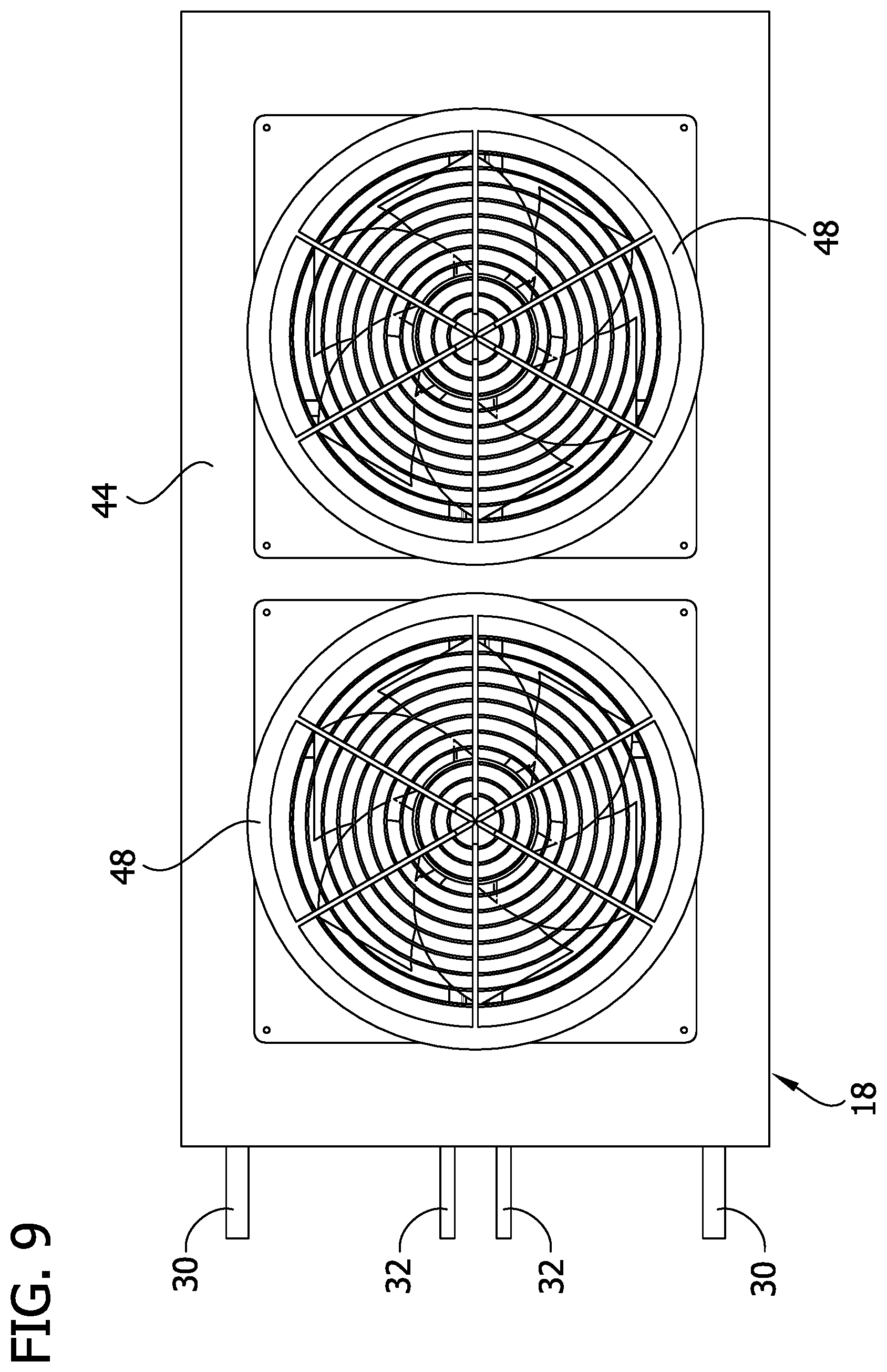
[0017] FIG. 9 is a top view of the condenser module;
[0018] FIG. 10 is a perspective of a heat exchanger of another embodiment;
[0019] FIG. 11 is a perspective of a heat exchanger of another embodiment;
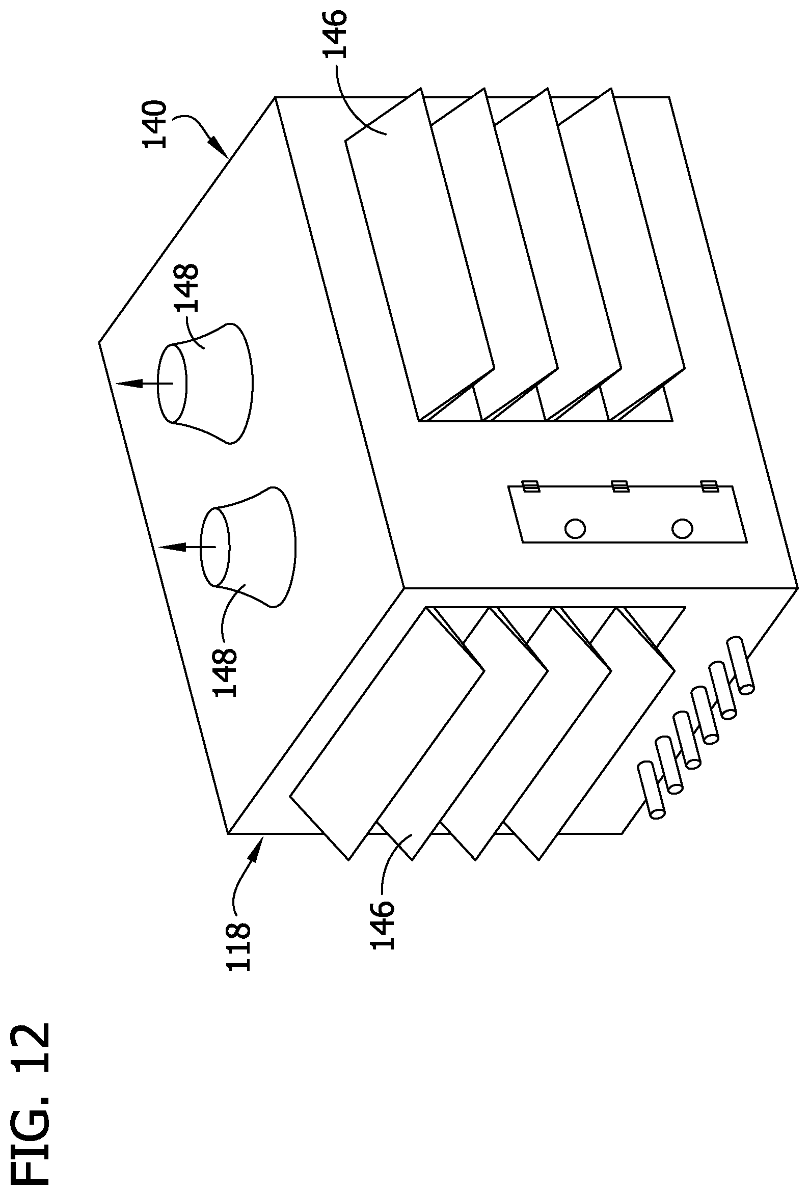
[0020] FIG. 12 is a schematic illustration of a condenser module of another embodiment; and
[0021] FIG. 13 is a schematic illustration of the condenser module of FIG. 12.
[0022] Corresponding reference characters indicate corresponding parts throughout the drawings.
DETAILED DESCRIPTION
[0023] Referring to FIGS. 2-4, a heat exchanger is generally indicated at reference number 10. The heat exchanger 10 comprises a heat pipe system 12 that is generally configured to exchange heat between warm and cool air streams. As will be appreciated by those skilled in the art, the heat pipe system 12 generally comprises one or more thermally conductive tubes charged with refrigerant such that the heat pipe system is configured to transfer heat between warm and cool air streams by the refrigerant cyclically changing phase from vapor to liquid and back to vapor. In one embodiment, the heat exchanger 10 is generally configured to provide heat recovery within a data center DC (FIG. 3). In the illustrated embodiment, the heat exchanger 10 is configured to provide heat recovery between an outside airstream OS passing outside of the data center DC, and an inside airstream IS flowing within the data center. In general, the outside air stream OS will comprise a relatively cool airstream and the inside airstream IS will comprise a relatively warm airstream. The heat exchanger 10 has a split configuration whereby the airstreams OS, IS are not within ducts that are disposed side-by-side within a ventilation system. Rather, the outside airstream OS remains outside of the data center, and the inside airstream IS remains inside of the data center. Thus, the heat pipe system 12 is split so that the thermally conductive tubes are positioned to encounter the separated airstreams. This system allows for heat recovery to occur between the outside and inside airstreams without having to construct complicated ductwork to bring the outside airstream into the data center DC, or carry the inside airstream out of the data center to bring the two airstreams together. It is envisioned that the heat exchanger 10 can be used with building structures other than data centers without departing from the scope of the disclosure.
[0024] Referring to FIGS. 3 and 4, the illustrated heat pipe system 12 comprises an inside heat pipe subassembly 14 (broadly, a first heat pipe subassembly) that is configured to be installed inside the data center DC in thermal communication with an inside air stream IS (e.g., return air) flowing through an inside duct ID, and an outside heat pipe subassembly 16 (broadly, a second heat pipe subassembly) that is configured to be installed outside of the data center DC in thermal communication with an outside air stream OS flowing through a housing 18 disposed outside of the data center. In the illustrated embodiment, each of the heat pipe subassemblies 14, 16 includes a heat pipe portion that is configured to be installed inside the respective airflow structure ID, 18. Thus, the heat pipe portions of the subassemblies 14, 16 are configured to be in direct thermal contact with the air streams OS, IS as the air streams flow through the airflow structures ID, 18 along the respective heat pipe portions. Heat pipe portions of the heat pipe subassemblies 14, 16 could also be installed in a climate control system in thermal communication with an air stream flowing through an airflow structure in other ways without departing from the scope of the invention. The inside duct ID may also include additional air moving and/or heat exchanging components such as fans 19 and cooling coils 21.
[0025] Each of the heat pipe subassemblies 14, 16 comprises a top header 20, a bottom header 22, and a plurality of heat pipes 24 that extend vertically between the top and bottom headers. The heat pipes 24 provide fluid communication between the respective top header 20 and the respective bottom header 22. Other configurations are also possible without departing from the scope of the invention. Each of the top and bottom headers 20, 22 can comprise a manifold having a main passage that is fluidly coupled to each of the heat pipes 24. The top and bottom headers 20, 22 may be located inside or outside of the respective airflow structures ID, 18. In the illustrated embodiment, the headers 20, 22 are located inside of the respective airflow structures ID, 18. In one or more embodiments, the top header 20 has a cross-sectional dimension (i.e., height) of at least 3 inches (7.6 cm). In one or more embodiments, the cross-sectional dimension of the top header 20 is greater than 3 inches (7.6 cm). The top header 20 could still have other dimensions without departing from the scope of the disclosure.
[0026] The vertical heat pipes 24 individually and collectively comprise heat pipe portions received in the respective airflow structure ID, 18. In one or more embodiments, the vertical heat pipes 24 extend along an entirety of a height of the respective structure ID, 18 and are spaced apart along a width of the respective duct. Two or more heat pipe subassemblies can also be vertically stacked inside the airflow structure ID, 18 in some embodiments. In certain embodiments, the vertical heat pipes 24 have a height that is greater than about 36 inches (about 91 cm), such as greater than about 40 inches (about 102 cm), greater than about 45 inches (about 114 cm), greater than about 50 inches (about 127 cm), greater than about 55 inches (about 140 cm), greater than about 60 inches (about 152.4 cm), greater than about 65 inches (about 165 cm), greater than about 70 inches (about 178 cm), about 75 inches (about 191 cm), etc. The heat pipes can also have other heights in one or more embodiments. In certain embodiments, each heat pipe 24 can have cross-sectional dimension (i.e., diameter) of between about 1/4 inch (0.6 cm) and about 3/4 inch (1.9 cm). In one or more embodiments, each heat pipe 24 has a diameter of at least about 1/4 inches (0.6 inches). In one or more embodiments, each heat pipe 24 has a diameter of about 1/2 inches (1.3 inches). Accordingly, the air streams IS, OS can flow through gaps between the heat pipes 24 as they flow through the respective airflow structures ID, 18. Referring to FIG. 4, only a single row of vertical heat pipes 24 is shown in the illustrated embodiment. In other embodiments, however, a plurality of rows of heat pipes can be spaced apart in the direction of air flow through the respective airflow structure ID, 18. In certain embodiments, the vertical heat pipes in a plurality of rows of heat pipes can be offset from one another along the width of the duct. Additional rows of vertical heat pipes can be fluidly coupled to the same headers 20, 22 or to different headers (e.g., there can be a dedicated header for each row of heat pipes or for a set of two or more rows of heat pipes). In one or more embodiments, heat transfer fins (not shown) extend along the width of each airflow structure ID, 18 at spaced apart locations along the height of each duct such that the respective airstream IS, OS can flow through the gaps between the fins. Suitably, each fin can comprise a thin strip of thermally conductive material that is thermally and physically connected to one or more vertical heat pipes 24 in the respective airflow structure ID, 18 to transfer heat between the respective heat pipes and the respective air stream IS, OS.
[0027] The heat pipe system 12 is charged with a refrigerant that is suitable for the temperature range of the climate control system in which the heat exchanger 10 is installed. Referring again to FIGS. 3 and 4, the inside heat pipe subassembly 14 is fluidly connected to the outside heat pipe subassembly 16 such that the refrigerant can flow through the heat pipe system 12 between the heat pipe subassemblies. More specifically, the illustrated heat pipe system 12 comprises a vapor conduit 30 that provides fluid communication between the top headers 20 of the heat pipe subassemblies 14, 16 and a liquid conduit 32 that provides fluid communication between the bottom headers 22 of the heat pipe subassemblies. The heat pipe system 12 thus defines a continuous refrigerant flow loop extending from the top header 20 of the inside heat pipe subassembly 14 in series through vapor conduit 30, the top header of the outside heat pipe subassembly 16, the heat pipes 24 of the outside heat pipe subassembly, the bottom header 22 of the outside heat pipe subassembly, the liquid conduit 32, the bottom header of the inside heat pipe subassembly, the heat pipes of the inside heat pipe subassembly, and back to the top header of the inside subassembly. Although the continuous refrigerant flow loop was described as proceeding in a clockwise direction through the passaging depicted in FIG. 4, it will be understood that the refrigerant can also flow in the opposite direction.
[0028] As will be explained in further detail below, the heat pipe system 12 is configured so that the inside heat pipe subassembly 14 functions as an evaporator (e.g., an evaporator heat pipe subassembly) that is configured to evaporate liquid refrigerant while the outside heat pipe subassembly 16 functions as a condenser (e.g., a condenser heat pipe subassembly) that is configured to condense refrigerant vapor. As will be appreciated by those skilled in the art, the heat pipe system 12 is configured to transfer heat from the warmer of the air streams IS to the cooler of the air streams OS as the refrigerant in the heat pipe system 12 flows between the evaporator heat pipe subassembly 14 and the condenser heat pipe subassembly 16. In instances such as when the heat pipe system 12 is installed in a data center, heat from the warm air stream IS is absorbed by evaporation of the refrigerant in the evaporator heat pipe subassembly 14, thereby cooling the warm air stream and warming the refrigerant. The warm, evaporated refrigerant flows through the top header 20 of the evaporator heat pipe subassembly 14 and through the vapor conduit 30 to the condenser heat pipe subassembly 16. In the condenser heat pipe subassembly 16, the cool air stream OS flows along the heat pipes 24 and condenses the warm refrigerant vapor. Condensation of the refrigerant transfers heat to the cool air stream OS, thereby warming the air stream and cooling the refrigerant. The cool, condensed refrigerant flows along the liquid conduit 32 back to the evaporator heat pipe subassembly 14. This heat recovery cycle can, in certain embodiments, continue passively in a closed loop. This occurs in part because of the outside air being cooler than the inside air within the data center.
[0029] In the illustrated embodiment, the evaporator subassembly 14 is located below the condenser subassembly 16 so that at least a portion of the vapor conduit 30 and the liquid conduit 32 must each extend generally vertically or inclined to connect the subassemblies. Accordingly, in the illustrated heat pipe system 12, refrigerant flow between the subassemblies is gravity-assisted (e.g., by orienting the liquid conduit 32 to slope toward the evaporator subassembly 14). In the illustrated embodiment, the heat pipe system 12 is free of any valves, pump, or compressors to drive the refrigerant flow through the heat pipe system. Thus, the heat pipe system 12 is entirely passive. The larger size of the top header 20 facilitates passive operation of the system by preventing pressure drop across the header which could otherwise occur with a conventional smaller header size. This also produces a more reliable heat pipe system as there are less components which may be subject to failure or malfunction over time. However, a pump could be used in certain embodiments without departing from the scope of the disclosure.
[0030] Referring to FIGS. 5-9, a condenser module is generally indicated at 40. The condenser module comprises housing 18 that is configured, in certain embodiments, to sit on a rooftop of a building structure such as a data center, and at least one condenser heat pipe subassembly 16 for transferring heat from the outside airstreams OS to the inside airstream IS. The housing 18 is generally hollow and provides a frame for the condenser module 40 for mounting the condenser module on the building structure. In the illustrated embodiment, an outer portion 42 of the housing 18 is formed generally in the shape of a rectangular prism. The outer portion 42 is open along its sides to provide airflow access to an inner portion 44 of the housing 18. The inner portion 44 of the housing 18 is formed generally in the shape of an upside down triangular prism. A mesh cover 46 is disposed over opposite open sides of the inner portion 44 covering the open sides. The inner portion 44 houses the condenser heat pipe subassemblies 16 whereby the subassemblies are positioned generally at the open sides of the inner portion. The upside down triangular prism shape of the inner portion 44 facilitates positioning the condenser heat pipe subassemblies 16 at an angle which reduces the overall height of the housing 18 and allows for less material to be used in making the housing. In the illustrated embodiment, the condenser heat pipe subassemblies 16 are angled such that the bottom of each subassembly is located closer to a midline of the housing 18 than the top of the subassembly. This generally points the condenser heat pipe subassemblies 16 downward, which along with the surrounding housing 18, helps to shield the subassemblies from the outside elements. The inner portion 44 of the housing 18 also mounts fans 48 on a top of the housing. The fans 48 are operable to draw the ambient outside air through the condenser module 40 for heat exchange. For example, the fans 48 may be controlled by a controller (not shown) to regulate the amount of air that is drawn into the condenser module 40 to control the amount of heat transfer that occurs. The fans 48 are received in openings in the top of the inner portion 44 of the housing 18. In the illustrated embodiment, there are two fans 48 mounted on the housing 18. However, any number of fans can be used and the location and arrangement of the fans can be other than shown without departing from the scope of the disclosure. The mesh covers 46 provide protection to the condenser heat pipe subassemblies 16 while permitting the outside air to be drawn into the condenser module 40 and across the subassemblies. Holes 50 may be provided in the outer portion 42 of the housing 18 to receive arms of a device (not shown) for lifting the condenser module 40.
[0031] Referring to FIGS. 2, 4, and 7, there are two condenser heat pipe subassemblies 16 housed within the housing 18 of the condenser module 40. The two subassemblies 16 are arranged in parallel with each other so that the outside air streams OS that contact both subassemblies 16 will each be at the ambient outside temperature. Therefore, heat exchange is maximized across both of the subassemblies 16. In particular, the parallel arrangement provides increased performance over an arrangement which places condenser heat pipe subassemblies in series because in a series arrangement the outside airstream is tempered by the initial heat pipe assembly reducing the effectiveness of the subsequent heat pipe assemblies which will receive a progressively more and more tempered airstream. However, by placing the condenser heat pipe subassemblies 16 in parallel, neither of the subassemblies receives tempered air. Thus, the temperature difference is maximized which increases the heat recovery capability of the system. In the illustrated embodiment, there are two subassemblies 16 in parallel. However, there could be any number of heat pipe subassemblies arranged in parallel in the housing 18 without departing from the scope of the disclosure.
[0032] Referring to FIG. 2, a heat exchanger 10 is shown incorporating three condenser modules 40 connected to evaporator heat pipe assemblies 14 disposed within the interior of a building structure BS. In the illustrated embodiment, there are two condenser heat pipe subassemblies 16 in each condenser module 40. Therefore, a first condenser heat pipe subassembly 16 in each condenser module 40 is connected by liquid and vapor conduits 32, 30 to a top evaporator heat pipe subassembly 14t, and a second condenser heat pipe subassembly 16 is connected by liquid and vapor conduits 32, 30 to a bottom evaporator heat pipe subassembly 14b. The top and bottom evaporator heat pipe subassemblies 14t, 14b are arranged in a stacked configuration and may be disposed within a duct inside of the building structure BS. In the illustrated embodiment, each evaporator heat pipe subassembly 14t, 14b includes three heat pipe sections arranged in series within the duct. Each heat pipe section is connected to a respective condenser heat pipe subassembly 16 in one of the condenser modules 40. Therefore, each heat recovery circuit includes one condenser coil and one evaporator coil. It will be understood that the evaporator heat pipe subassemblies 14 could have other configurations without departing from the scope of the disclosure.
[0033] Referring to FIG. 10, a heat exchanger 10' is shown including two condenser modules 40 connected to each other in series and connected to evaporator heat pipe assemblies 14 disposed within the interior of a building structure BS. In the illustrated embodiment, there are two condenser heat pipe subassemblies 16 in each condenser module 40. Therefore, a first heat pipe subassembly 16 of a first condenser module 40A is connected to a first heat pipe subassembly of a second condenser module 40B, and a second heat pipe subassembly 16 of the first condenser module 40A is connected to a second heat pipe subassembly 16 of a the second condenser module 40B. Further, the first condenser heat pipe subassembly 16 of the second condenser module 40B is connected by liquid and vapor conduits 32, 30 to a top evaporator heat pipe subassembly 14t, and the second condenser heat pipe subassembly 16 of the second condenser module 40B is connected by liquid and vapor conduits to a bottom evaporator heat pipe subassembly 14b. The top and bottom evaporator heat pipe subassemblies 14t, 14b are arranged in a stacked configuration and may be disposed within a duct in the inside of the building structure BS. In the illustrated embodiment, each evaporator heat pipe subassembly 14t, 14b includes three heat pipe sections arranged in series within the duct. The heat pipe sections of the top evaporator heat pipe subassembly 14t are connected to the first condenser heat pipe subassembly 16 in the second condenser module 40B, and the heat pipe section of the bottom evaporator heat pipe subassembly 14b are connected to the second condenser heat pipe subassembly 16 in the second condenser module 40B. Each of the vapor conduits 30 and liquid conduits 32 have three branch sections 56, 58, respectively, that connect the vapor and liquid conduits to the three heat pipe sections in the evaporator heat pipe subassemblies 14. Therefore, each heat recovery circuit includes one condenser coil and three evaporator coils. To achieve the same overall heat recovery performance as a similar system where the evaporator heat pipe subassembly 14 does not have a stacked configuration (such as the arrangement shown in FIG. 11), the coils of the condenser heat pipe subassemblies 16 of this embodiment may be sized to be twice as long as the condenser coils used with the non-stacked evaporator coil assembly. It will be understood that the evaporator heat pipe subassemblies 14 could have other configurations without departing from the scope of the disclosure. For example, any number of heat pipe sections could be used in the evaporator heat pipe subassemblies 14 used in connection with the condenser modules 40 in this embodiment. To this effect, if the evaporator heat pipe subassemblies 14 include only one heat pipe section then the vapor and liquid conduits 30, 32 will not include branch sections. Similarly, if the evaporator heat pipe subassemblies 14 include two or more than three heat pipe sections then the vapor and liquid conduits 30, 32 will have a corresponding number of branch sections 56, 58 to properly connect the condenser heat pipe subassemblies 16 to the evaporator heat pipe subassemblies.
[0034] Referring to FIG. 11, a heat exchanger 10'' is shown including one condenser module 40 connected to an evaporator heat pipe subassembly 14 disposed within the interior of a building structure BS. In the illustrated embodiment, there are two condenser heat pipe subassemblies 16 in the condenser module 40. Each condenser heat pipe subassembly 16 includes a vapor conduit 30 and a liquid conduit 32. The vapor conduits 30 of the condenser heat pipe subassemblies 16 are connected to each other, and the liquid conduits 32 of the subassemblies are connected to each other so that a single vapor conduit section 60 and a single liquid conduit section 62 extends between the condenser module 40 and the evaporator heat pipe subassembly 14 in the building structure BS. In the illustrated embodiment, the single vapor conduit section 60 and single liquid conduit section 62 each branch into the three separate vapor and conduit sections 64, 66, respectively, for supplying fluid to the three heat pipe sections of the evaporator heat pipe subassembly 14. Therefore, the heat recovery circuit includes two condenser coil and three evaporator coils. It will be understood that there could be any number of evaporator heat pipe sections used in connection with the condenser module 40 in this embodiment. For example, if the evaporator heat pipe subassembly 14 included only one heat pipe section then the single vapor conduit section 60 and the single liquid conduit section 62 will connect directly to the single heat pipe section of the evaporator heat pipe subassembly.
[0035] Referring to FIGS. 12 and 13, a condenser module of another embodiment is generally indicated at 140. The condenser module 140 is similar to the condenser module 40 and thus like parts are given the same reference number plus 100. The condenser module 140 operates in substantially the same manner as the condenser module 40 of the first embodiment except as otherwise provided herein. In particular, the condenser module 140 includes a housing 118 configured to sit on a rooftop of a building structure such as a data center, and at least one condenser heat pipe subassembly 116 for transferring heat from an outside airstream to an inside airstream within the building structure. The housing 118 is generally hollow and provides a frame for the condenser module 140 for mounting the condenser module on the building structure. In the illustrated embodiment, the housing 18 has a generally rectangular prism shape. However, the housing 118 could have any shape without departing from the scope of the disclosure. In the illustrated embodiment, the housing 118 has openings 143 along three sides to provide airflow access to an inner portion 144 of the housing 118. Shutters 146 may be disposed over the openings 143 to control the amount of airflow that enters the housing 118. The inner portion 144 of the housing 118 houses the condenser heat pipe subassemblies 116 whereby the subassemblies are positioned generally at the openings 143. In the illustrated embodiment, there are three condenser heat pipe subassemblies 116 for each of the openings 143 and the subassemblies are oriented generally vertically within the housing 118. The housing 118 also mounts fans 148 on a top of the housing. The fans 148 are operable to draw the ambient outside air through the condenser module 140 for heat exchange. In the illustrated embodiment, there are two fans 148 mounted on the housing 118. However, any number of fans can be used and the location and arrangement of the fans can be other than shown without departing from the scope of the disclosure. The shutters 146 provide protection to the condenser heat pipe subassemblies 116 while permitting the outside air to be drawn into the condenser module 40 and across the subassemblies.
[0036] When introducing elements of the present invention or the preferred embodiment (s) thereof, the articles "a", "an", "the" and "said" are intended to mean that there are one or more of the elements. The terms "comprising", "including" and "having" are intended to be inclusive and mean that there may be additional elements other than the listed elements.
[0037] In view of the above, it will be seen that the several objects of the invention are achieved and other advantageous results attained.
[0038] As various changes could be made in the above products and methods without departing from the scope of the invention, it is intended that all matter contained in the above description shall be interpreted as illustrative and not in a limiting sense.
* * * * *
D00000
D00001
D00002
D00003
D00004
D00005
D00006
D00007
D00008
D00009
D00010
D00011
D00012
D00013

XML
uspto.report is an independent third-party trademark research tool that is not affiliated, endorsed, or sponsored by the United States Patent and Trademark Office (USPTO) or any other governmental organization. The information provided by uspto.report is based on publicly available data at the time of writing and is intended for informational purposes only.
While we strive to provide accurate and up-to-date information, we do not guarantee the accuracy, completeness, reliability, or suitability of the information displayed on this site. The use of this site is at your own risk. Any reliance you place on such information is therefore strictly at your own risk.
All official trademark data, including owner information, should be verified by visiting the official USPTO website at www.uspto.gov. This site is not intended to replace professional legal advice and should not be used as a substitute for consulting with a legal professional who is knowledgeable about trademark law.