Reciprocating Compressor With Improved Valve Cylinder Assembly
Delmotte; Scott J.
U.S. patent application number 17/041730 was filed with the patent office on 2021-03-18 for reciprocating compressor with improved valve cylinder assembly. The applicant listed for this patent is Dresser-Rand Company. Invention is credited to Scott J. Delmotte.
| Application Number | 20210079908 17/041730 |
| Document ID | / |
| Family ID | 1000005273046 |
| Filed Date | 2021-03-18 |
| United States Patent Application | 20210079908 |
| Kind Code | A1 |
| Delmotte; Scott J. | March 18, 2021 |
RECIPROCATING COMPRESSOR WITH IMPROVED VALVE CYLINDER ASSEMBLY
Abstract
A reciprocating compressor with an improved valve assembly is disclosed. Compressor includes a cylinder block having a cylinder that defines a cylindrical bore extending longitudinally along a bore axis. Cylinder block includes a hollow chamber extending longitudinally along a chamber axis, which is non-intersecting relative to the bore axis. Valve assembly is disposed in hollow chamber. Valve assembly is made up of an axially-stacked arrangement of components extending along chamber axis. The axially-stacked arrangement of components is spaced apart from a wall that forms a perimeter of the cylinder and is thus free from mechanical interference with the perimeter of the cylinder.
| Inventors: | Delmotte; Scott J.; (Mansfield, PA) | ||||||||||
| Applicant: |
|
||||||||||
|---|---|---|---|---|---|---|---|---|---|---|---|
| Family ID: | 1000005273046 | ||||||||||
| Appl. No.: | 17/041730 | ||||||||||
| Filed: | July 13, 2018 | ||||||||||
| PCT Filed: | July 13, 2018 | ||||||||||
| PCT NO: | PCT/US2018/042007 | ||||||||||
| 371 Date: | September 25, 2020 |
Related U.S. Patent Documents
| Application Number | Filing Date | Patent Number | ||
|---|---|---|---|---|
| 62662329 | Apr 25, 2018 | |||
| Current U.S. Class: | 1/1 |
| Current CPC Class: | F04B 39/10 20130101; F04B 39/14 20130101; F04B 39/122 20130101 |
| International Class: | F04B 39/10 20060101 F04B039/10; F04B 39/12 20060101 F04B039/12 |
Claims
1. A reciprocating compressor comprising: a cylinder block including a cylinder that defines a cylindrical bore extending longitudinally along a bore axis, the cylinder block including a hollow chamber extending longitudinally along a chamber axis, which is non-intersecting relative to the bore axis; and a valve assembly disposed in the hollow chamber, the valve assembly comprising an axially-stacked arrangement of components extending along the chamber axis, the axially-stacked arrangement of components spaced apart from a wall that forms a perimeter of the cylinder, and thus free from mechanical interference with the perimeter of the cylinder.
2. The reciprocating compressor of claim 1, wherein the bore axis and the chamber axis are mutually orthogonal axes.
3. The reciprocating compressor of claim 1, further comprising a pair of valve covers affixed to mutually opposed sides of the cylinder block to retain in axial compression within the hollow chamber the axially-stacked arrangement of components.
4. The reciprocating compressor of claim 1, further comprising an inlet passageway formed in the cylinder block, and wherein the axially-stacked arrangement of components includes a suction valve in fluid communication with the inlet passageway.
5. The reciprocating compressor of claim 4, further comprising an outlet passageway formed in the cylinder block, and wherein the axially-stacked arrangement of components includes a discharge valve in fluid communication with the outlet passageway.
6. The reciprocating compressor of claim 4, wherein the axially-stacked arrangement of components includes a spacer interposed between the suction valve and the discharge valve.
7. The reciprocating compressor of claim 5, further comprising a passageway arranged to provide fluid communication through the spacer between the cylindrical bore with the suction valve and the discharge valve.
8. The reciprocating compressor of claim 4, further comprising a perimeter fluid seal disposed at a perimeter joint between the suction valve and the spacer.
9. The reciprocating compressor of claim 5, further comprising a perimeter fluid seal disposed at a perimeter joint between the discharge valve and the spacer.
10. The reciprocating compressor of claim 1, wherein the cylinder comprises a double-action cylinder, wherein the cylinder block includes a further hollow chamber extending longitudinally along a further chamber axis, which is non-intersecting relative to the bore axis, the further chamber axis spaced apart from the chamber axis along the bore axis.
11. The reciprocating compressor of claim 10, comprising a further valve assembly disposed in the further hollow chamber, the further valve assembly comprising a further axially-stacked arrangement of components extending along the further chamber axis, the further axially-stacked arrangement of components spaced apart from the wall that defines the perimeter of the cylinder, and thus free from mechanical interference with the perimeter of the cylinder.
12. The reciprocating compressor of claim 11, wherein the bore axis and the further chamber axis are mutually orthogonal axes.
13. The reciprocating compressor of claim 12, comprising a further pair of valve covers affixed to the mutually opposed sides of the cylinder block to retain in axial compression within the further hollow chamber the further axially-stacked arrangement of components.
14. The reciprocating compressor of claim 10, comprising an inlet passageway formed in the cylinder block, and wherein the arrangement of further axially-stacked components includes a further suction valve in fluid communication with the inlet passageway.
15. The reciprocating compressor of claim 14, comprising an outlet passageway formed in the cylinder block, and wherein the further axially-stacked arrangement of components includes a further discharge valve in fluid communication with the outlet passageway.
16. The reciprocating compressor of claim 4, wherein the further axially-stacked arrangement of components includes a further spacer interposed between the further suction valve and the further discharge valve.
17. The reciprocating compressor of claim 15, a further passageway arranged to provide fluid communication through the further spacer between the cylindrical bore with the further suction valve and the further discharge valve.
18. The reciprocating compressor of claim 14, comprising a further perimeter fluid seal disposed at a perimeter joint between the further suction valve and the further spacer.
19. The reciprocating compressor of claim 15, comprising a further perimeter fluid seal disposed at a perimeter joint between the further discharge valve and the further spacer.
20. The reciprocating compressor of claim 1, wherein the valve assembly is arranged with a respective tilt angle relative to a local gravity vector, wherein the tilt angle is in a range from -90.degree. to 90.degree. relative to the local gravity vector.
Description
[0001] This application claims benefit of the Apr. 25, 2018 filing date of U.S. provisional application 62/662,329, which is incorporated by reference herein.
BACKGROUND
1. Field
[0002] Disclosed embodiments are generally related to gas compressors, and, more particularly to reciprocating compressors cylinders having an improved valve assembly.
2. Description of the Related Art
[0003] Reciprocating compressors are machines that are widely-employed in a variety of industrial applications. A reciprocating compressor includes a body or cylinder defining a compression chamber and a piston movably disposed within the cylinder chamber. Linear reciprocating displacement of the piston within the chamber compresses gas (commonly referred to as "process" fluid or gas) located within the chamber, which is subsequently discharged at the increased pressure, such as by way of valves that may be respectively positioned upon respective valve seats constructed in the body (e.g., a wall) of the compressor cylinder that defines a compressor cylinder bore. For various considerations, it is desirable to further improve the maintainability, durability and overall reliability of the compressor cylinder design. See U.S. Pat. Nos. 5,209,647 and 5,011,383 for respective examples of reciprocating compressors involving valve assemblies.
BRIEF DESCRIPTION OF THE DRAWINGS
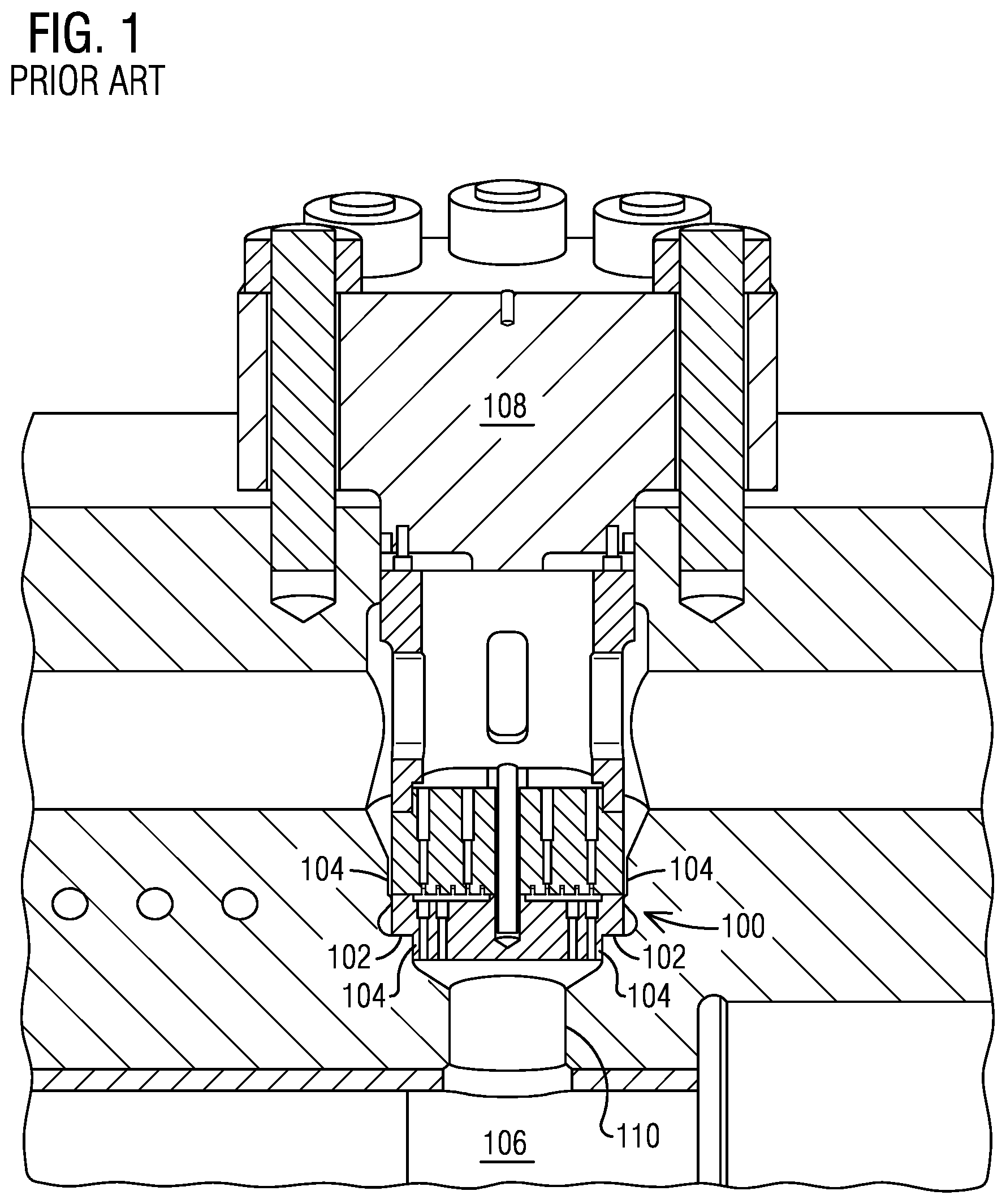
[0004] FIG. 1 is fragmentary side view of a prior art valve design for a reciprocating compressor.
[0005] FIGS. 2 and 3 respectively illustrate a fragmentary side view and a fragmentary end view of one nonlimiting embodiment of a disclosed valve assembly arranged vertically in a reciprocating compressor.
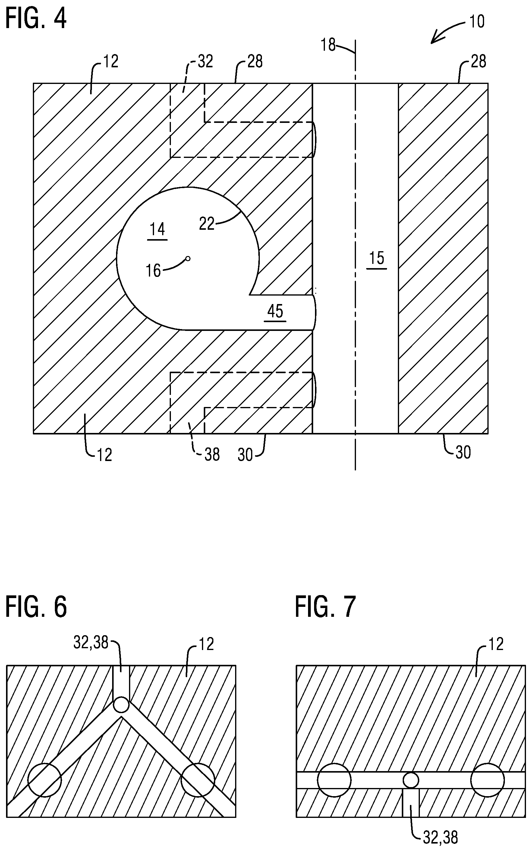
[0006] FIG. 4 corresponds to the fragmentary end view shown in FIG. 3, where the disclosed valve assembly is omitted to better appreciate spatial relationships between a hollow chamber where the valve assembly is disposed and a cylindrical bore, where a piston is accommodated.
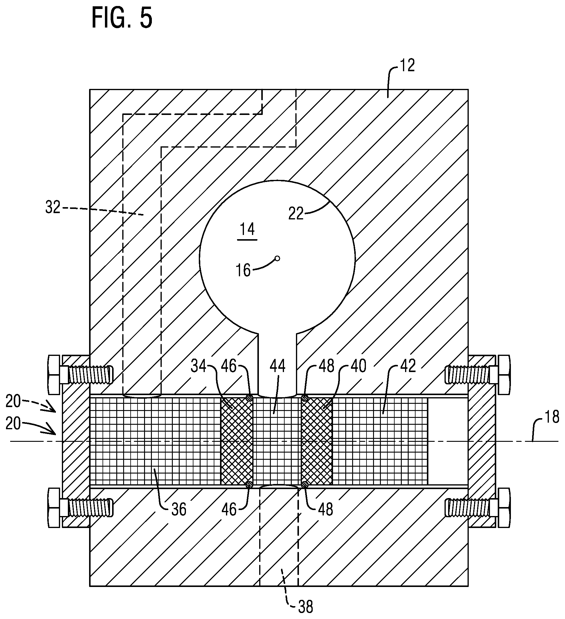
[0007] FIG. 5 illustrate a fragmentary end view of another nonlimiting embodiment of a disclosed valve assembly arranged horizontally in a reciprocating compressor.
[0008] FIGS. 6 and 7 respectively illustrate fragmentary side views of non-limiting embodiments of inlet or outlet passageways, as may be constructed in the cylinder block of the reciprocating compressor shown in FIG. 5.
DETAILED DESCRIPTION
[0009] The inventor of the present invention has recognized certain issues in connection with certain prior art designs directed to reciprocating compressor cylinders. FIG. 1 is illustrative of one such prior art valve compressor design. These prior art designs typically involve a compressor valve 100 positioned upon a feature 102 (e.g., a valve seat, indent, notch, etc.) constructed in a body 104 (e.g., a wall) of the compressor cylinder that defines a compressor cylinder bore 106. A substantial magnitude of force is generally required from a valve cap 108 to hold the valve in place and resist the differential pressure (e.g., in certain applications this pressure can reach 10,000 psi and higher) that is formed between cylinder bore 106 and a valve passage 110. This substantial force can lead to highly concentrated mechanical stresses on the valve seat. These stresses tend to limit the cylinder pressure capabilities and can often lead to structural failure at valve seat 102 and/or compressor cylinder wall 104 from overstress conditions. Overstress can occur due to a variety of reasons, such as from variable pressure conditions during operation of the compressor, over-torque of the valve cover studs during deployment or servicing, etc.
[0010] Thick valve seats 102--constrained to the smallest size valve possible in a given implementation--have been proposed to attempt to alleviate the stress concentration by limiting the surface area for the pressure to act upon. However, there are practical limits where even a thicker valve seat no longer provides practical stress reduction, and thus resulting in suboptimal capability for the maximum pressure that can be reliably accommodated in such prior art compressor cylinder designs.
[0011] In view of such recognition, the present inventor proposes an innovative valve assembly effective to provide a reliable and relatively low-cost technical solution to solve at least the issues mentioned above.
[0012] In the following detailed description, various specific details are set forth in order to provide a thorough understanding of such embodiments. However, those skilled in the art will understand that disclosed embodiments may be practiced without these specific details that the aspects of the present invention are not limited to the disclosed embodiments, and that aspects of the present invention may be practiced in a variety of alternative embodiments. In other instances, methods, procedures, and components, which would be well-understood by one skilled in the art have not been described in detail to avoid unnecessary and burdensome explanation.
[0013] Furthermore, various operations may be described as multiple discrete steps performed in a manner that is helpful for understanding embodiments of the present invention. However, the order of description should not be construed as to imply that these operations need be performed in the order they are presented, nor that they are even order dependent, unless otherwise indicated. Moreover, repeated usage of the phrase "in one embodiment" does not necessarily refer to the same embodiment, although it may. It is noted that disclosed embodiments need not be construed as mutually exclusive embodiments, since aspects of such disclosed embodiments may be appropriately combined by one skilled in the art depending on the needs of a given application.
[0014] The terms "comprising", "including", "having", and the like, as used in the present application, are intended to be synonymous unless otherwise indicated. Lastly, as used herein, the phrases "configured to" or "arranged to" embrace the concept that the feature preceding the phrases "configured to" or "arranged to" is intentionally and specifically designed or made to act or function in a specific way and should not be construed to mean that the feature just has a capability or suitability to act or function in the specified way, unless so indicated.
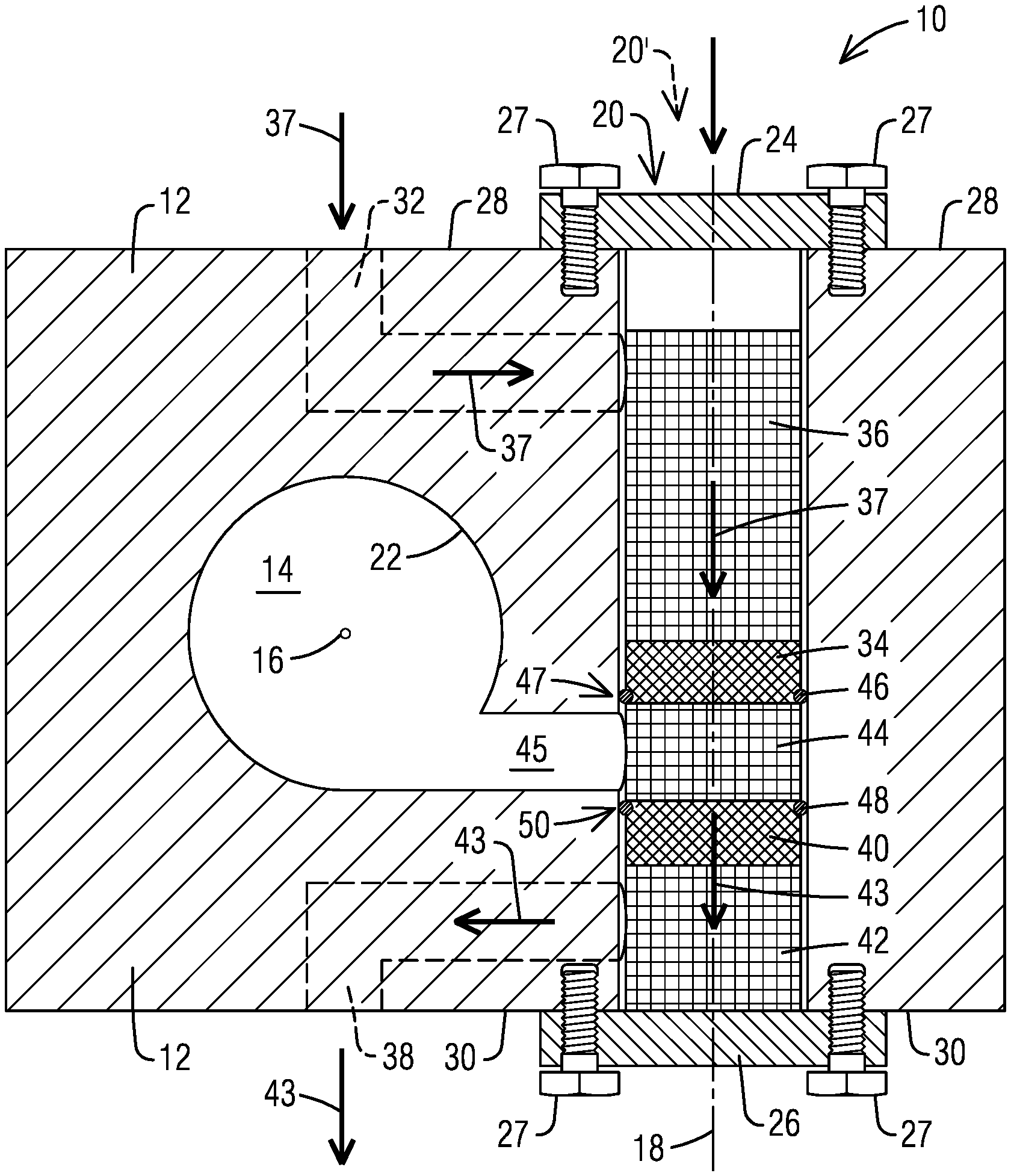
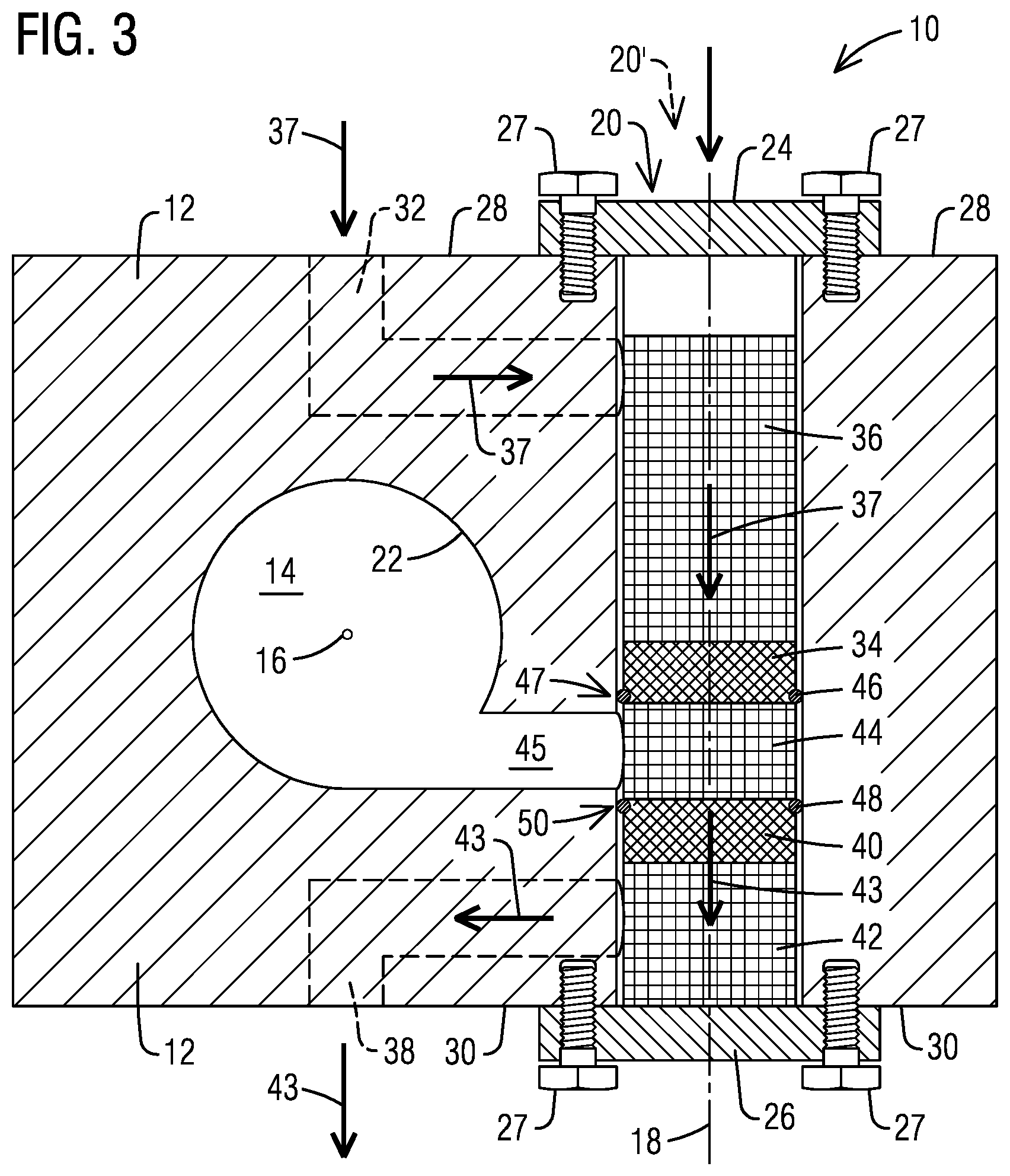
[0015] FIGS. 2 and 3 respectively illustrate a fragmentary side view and a fragmentary end view of a reciprocating compressor 10 that can benefit from a disclosed valve assembly 20. Reciprocating compressor 10 may comprise a cylinder block 12 including a cylinder that defines a cylindrical bore 14 extending longitudinally along a bore axis 16. For simplicity of illustration and to avoid visual cluttering, elements which are superfluous relative to disclosed embodiments have been omitted. For example, omitted elements include cylinders heads, piston and piston rod components. Cylinder block 12 includes a hollow chamber 15 (FIG. 4) extending longitudinally along a chamber axis 18, which is non-intersecting relative to bore axis 16. Without limitation, valve assembly 20 is disposed in hollow chamber 15.
[0016] Without limitation, valve assembly 20 comprises an axially-stacked arrangement of components extending along chamber axis 18. The axially-stacked arrangement of components is spaced apart from a wall 22 that forms a perimeter of the cylinder, and thus is free from mechanical interference with the perimeter of the cylinder. A pair of valve covers 24, 26 may be affixed via suitable affixing means 27 (e.g., bolts) to mutually opposed sides 28, 30 of cylinder block 12 to retain in axial compression within the hollow chamber the axially-stacked arrangement of components.
[0017] In one non-limiting embodiment, an inlet passageway 32 may be formed in cylinder block 12. In one non-limiting embodiment, the axially-stacked arrangement of components includes a suction valve 34, as may be located downstream from a respective valve cage 36. Suction valve 34 is in fluid communication with inlet passageway 32, (as schematically represented by arrows 37).
[0018] In one non-limiting embodiment, an outlet passageway 38 may also be formed in cylinder block 12. In one non-limiting embodiment, the axially-stacked arrangement of components includes a discharge valve 40 as may be located upstream from a respective valve cage 42. Discharge valve 40 is in fluid communication with outlet passageway, (as schematically represented by arrows 43).
[0019] In one non-limiting embodiment, the axially-stacked arrangement of components includes a spacer 44 interposed between suction valve 34 and discharge valve 40. A passageway 45 (FIG. 3) is arranged in cylinder block 12 to provide fluid communication through spacer 44 between cylindrical bore 14 with suction valve 34 and discharge valve 40.
[0020] In one nonlimiting embodiment, a perimeter fluid (e.g., gas) seal 46 (FIG. 3) is disposed at a perimeter joint 47 between suction valve 34 and spacer 44. Similarly, a perimeter fluid seal 48 is disposed at a perimeter joint 50 between discharge valve 40 and spacer 44. This seal arrangement is different than in the prior art design, which is commonly arranged to seal on the face of the valve. Without limitation, examples of high-pressure seal arrangements that may be used may include O-rings, Chevron seal arrangements, such as may involve composite metal/polymer Chevron sealing arrangements; non-metallic C-seals, T-seals, labyrinth seals; piston rings seals, etc.
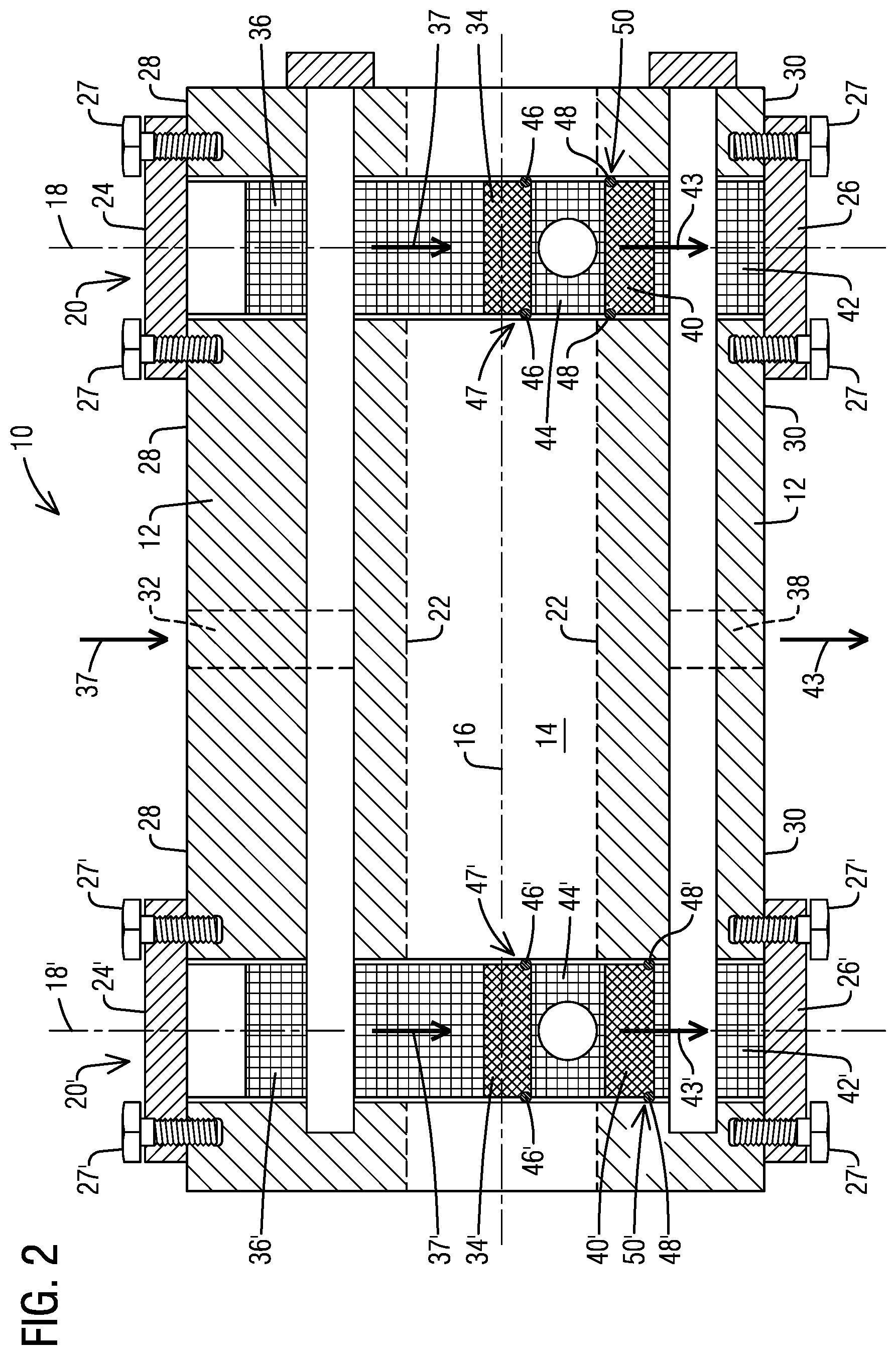
[0021] In one nonlimiting embodiment, the cylinder may comprise a double-action cylinder, and cylinder block 12, may include a further hollow chamber extending longitudinally along a further chamber axis 18' (FIG. 2), which is non-intersecting relative to bore axis 16. Without limitation, further chamber axis 18' is spaced apart from chamber axis 18 along bore axis 16. Bore axis 16 and further chamber axis 18' may be mutually orthogonal axes.
[0022] A further valve assembly 20' (FIG. 2) may be disposed in the further hollow chamber. The further valve assembly 20' may comprise a further axially-stacked arrangement of components extending along further chamber axis 18'. As discussed in the context of valve assembly 20, the further axially-stacked arrangement of components is spaced apart from wall 22 that defines the perimeter of the cylinder and is thus free from mechanical interference with the perimeter of the cylinder. A further pair of valve covers 24', 26' may be affixed to the mutually opposed sides 28, 30 of cylinder block 12 to retain in axial compression within the further hollow chamber the further axially-stacked arrangement of components.
[0023] Without limitation, the arrangement of further axially-stacked components that makes up valve assembly 20' includes a further suction valve 34', as may be located downstream from a respective valve cage 36'. Further suction valve 34' is in fluid communication with inlet passageway 32, (as schematically represented by arrows 37' (FIG. 2)).
[0024] In one non-limiting embodiment, the further axially-stacked arrangement of components that makes up valve assembly 20' includes a further discharge valve 40', as may be located upstream from a respective valve cage 42'. Further discharge valve 40' is in fluid communication with outlet passageway, (as schematically represented by arrows 43' FIG. 3)). The further axially-stacked arrangement of components includes a further spacer 44' interposed between further suction valve 34' and further discharge valve 40'. A further passageway (analogous to passage way 45 in FIG. 3)) is arranged to provide fluid communication through the further spacer 44' between cylindrical bore 14 with further suction valve 34' and further discharge valve 40'.
[0025] A further perimeter fluid seal 46' is disposed at a perimeter joint 47' between further suction valve 34' and further spacer 44'. Similarly, a further perimeter fluid seal 48' disposed at a perimeter joint 50' between the discharge valve 40' and further spacer 44'.
[0026] In one non-limiting embodiment, as may be appreciated in FIGS. 2 and 3, respective chamber axes 18 and 18' may be vertical axes and valve assemblies 20 and 20' may be vertically arranged. Without limitation, chamber axes 18 and 18' may be in correspondence with a local gravity vector; and thus, in this case, mutually opposed sides 28, 30 of cylinder block 12 would define respective top and bottom sides of cylinder block 12.
[0027] It will be appreciated, however, that chamber axes 18 and 18' need not be vertically positioned, and, without limitation, valve assemblies 20 and 20' may be horizontally arranged, as can be appreciated in FIG. 5. In this case, valve assembly 20 extends horizontally along chamber axis 18, which in this example is horizontally positioned. Without limitation, in this case chamber axes 18 and 18' would be transverse with respect to a local gravity vector; and thus, in this case, mutually opposed sides 28, 30 of cylinder block 12 would define respective lateral sides of cylinder block 12. Valve assembly 20' would be similarly positioned as valve assembly 20. As would be appreciated by one skilled in the art, an observer from behind the plane of the paper (that shows FIG. 5) would view valve assembly 20' in the same manner that valve assembly is seen in FIG. 5. It is contemplated that chamber axes 18 and 18' need not necessarily be vertically, or horizontally positioned, and, could be positioned at a respective angle in a range from -90.degree. to 90.degree. relative to the local gravity vector. Accordingly, without limitation, valve assemblies 20 and 20' may be arranged with a respective tilt angle relative to the local gravity vector. That is, at a respective angle in a range from -90.degree. to 90.degree. relative to the local gravity vector.
[0028] FIGS. 6 and 7 illustrates respective side views of non-limiting examples of inlet passageway 32 or outlet passageway 38 as may be constructed in cylinder block 12. For example, at least respective portions of inlet passageway 32 or outlet passageway 38 may respectively comprise a respective angled arrangement, as shown in FIG. 6. Alternatively, at least respective portions of inlet passageway 32 or outlet passageway 38 may respectively comprise a T-shaped arrangement, as shown in FIG. 7.
[0029] In operation, disclosed embodiments effectively provide an arrangement of individual components (e.g., respective valve cages 36, 42, respective valves such as suction valves 34 and discharge valves 40) loaded axially in compression with each other to form a self-supporting valve assembly. Advantageously, disclosed embodiments do not involve features in the cylinder wall for retaining any of the stacked components.
[0030] Without limitation, outlet passageway 38 may be located at the bottom of the cylinder (at a lower location relative to inlet passageway 32) to prevent (e.g., by way of gravity action) possible accumulation of liquids in the cylinder. Communication of the gas to the external cylinder connections may be accomplished through the use of standard machined gas passages constructed using techniques well-understood to those skilled in the art.
[0031] FIGS. 2 and 3 illustrate the use of one axially-stacked valve assembly per end of a given double acting cylinder. It will be appreciated that other alternate embodiments may be realized depending on the needs of a given application. For example, one could arrange multiple assemblies on one or both ends of the compressor cylinder.
[0032] It should now be appreciated that the disclosed valve assembly relocates the valves (and associated components) to a location spaced apart from the cylinder. Advantageously, this location is free from any mechanical interference or impingement with cylinder features, as would be the case in prior art designs that involve features (e.g., valve seat, notch, etc.) constructed in the body of the cylinder to support the valves.
[0033] The force necessary to hold the respective valves against the differential pressure of the cylinder is applied to a purely-axial stack of individual components, none of which impinge upon features in the cylinder wall that defines the cylinder bore. In disclosed embodiments, the concept of features that define a valve seat constructed in the cylinder body is no longer applicable. Accordingly, the above-described pressure limitation of prior art cylinder designs resulting from the valve seat stresses is overcome. The arrangement of axially-stacked valve assembly involves a pair of valve covers disposed at mutually opposed axial ends of the assembly. Thus, the anchoring of the axially-stacked valve assembly is fully independent from features in the body of the cylinder.
[0034] In operation, disclosed embodiments provide a cost-effective and reliable technical solution to solve a significant operational issue related to high pressure cylinder operation. Disclosed embodiments are believed to be effective for reliably supplying relatively higher pressures in, for example, double-acting cylinders than have been achievable prior to the present invention.
[0035] While embodiments of the present disclosure have been disclosed in exemplary forms, it will be apparent to those skilled in the art that many modifications, additions, and deletions can be made therein without departing from the scope of the invention and its equivalents, as set forth in the following claims.
* * * * *
D00000
D00001
D00002
D00003
D00004
D00005
XML
uspto.report is an independent third-party trademark research tool that is not affiliated, endorsed, or sponsored by the United States Patent and Trademark Office (USPTO) or any other governmental organization. The information provided by uspto.report is based on publicly available data at the time of writing and is intended for informational purposes only.
While we strive to provide accurate and up-to-date information, we do not guarantee the accuracy, completeness, reliability, or suitability of the information displayed on this site. The use of this site is at your own risk. Any reliance you place on such information is therefore strictly at your own risk.
All official trademark data, including owner information, should be verified by visiting the official USPTO website at www.uspto.gov. This site is not intended to replace professional legal advice and should not be used as a substitute for consulting with a legal professional who is knowledgeable about trademark law.