Rocker Arm For An Internal Combustion Engine
Copper; Anthony
U.S. patent application number 17/022952 was filed with the patent office on 2021-03-18 for rocker arm for an internal combustion engine. The applicant listed for this patent is Koyo Bearings North America LLC. Invention is credited to Anthony Copper.
| Application Number | 20210079815 17/022952 |
| Document ID | / |
| Family ID | 1000005102405 |
| Filed Date | 2021-03-18 |


| United States Patent Application | 20210079815 |
| Kind Code | A1 |
| Copper; Anthony | March 18, 2021 |
ROCKER ARM FOR AN INTERNAL COMBUSTION ENGINE
Abstract
A rocker arm for use in a valvetrain of a vehicle, having a body portion including two opposed side wall portions, each defining a bearing aperture therein and including a bearing boss disposed along a perimeter of the corresponding bearing aperture. A support bearing has a pair of opposed ends, each opposed end being received in a corresponding bearing aperture, and each bearing boss includes a first portion having a first radial thickness and a second portion having a second radial thicknesses, the first radial thickness being greater than the second radial thickness.
| Inventors: | Copper; Anthony; (Fountain Inn, SC) | ||||||||||
| Applicant: |
|
||||||||||
|---|---|---|---|---|---|---|---|---|---|---|---|
| Family ID: | 1000005102405 | ||||||||||
| Appl. No.: | 17/022952 | ||||||||||
| Filed: | September 16, 2020 |
Related U.S. Patent Documents
| Application Number | Filing Date | Patent Number | ||
|---|---|---|---|---|
| 62901081 | Sep 16, 2019 | |||
| Current U.S. Class: | 1/1 |
| Current CPC Class: | F01L 1/047 20130101; F01L 1/182 20130101 |
| International Class: | F01L 1/18 20060101 F01L001/18 |
Claims
1. A rocker arm for use in a valvetrain of a vehicle, comprising: a body portion including two opposed side wall portions, each side wall portion defining a bearing aperture therein, each side wall portion including a bearing boss disposed along a perimeter of the corresponding bearing aperture and extending outwardly from the corresponding side wall portion; and a support member having a pair of opposed ends, each opposed end being received in a corresponding bearing aperture, wherein each bearing boss includes a first portion having a first radial thickness and a second portion having a second radial thicknesses, the first radial thickness being greater than the second radial thickness.
2. The rocker arm of claim 1, wherein each bearing boss is asymmetric about the corresponding bearing aperture.
3. The rocker arm of claim 1, wherein the first portion of the bearing boss is disposed below the second portion of the bearing boss.
4. The rocker arm of claim 1, further comprising a pair of radial roller bearings, each radial roller bearing being both disposed on a corresponding one of the opposed ends of the support member and disposed within a corresponding one of the bearing apertures.
5. The rocker arm of claim 1, further comprising a pair of strengthening ribs, each strengthening rib extending outwardly from the first portion of a corresponding bearing boss.
6. The rocker arm of claim 5, wherein each strengthening rib lies in a plane that is transverse to the corresponding bearing boss.
7. The rocker arm of claim 1, wherein the support member is affixed to an upper end of a stud member.
8. A rocker arm for use in a valvetrain of a vehicle, comprising: a body portion including two opposed side wall portions, each side wall portion defining a circular bearing aperture therein, each side wall portion including a bearing boss disposed along a perimeter of the corresponding bearing aperture and extending outwardly from the corresponding side wall portion, each bearing boss having a circular outer perimeter; and a support member having a pair of opposed ends, each opposed end being received in a corresponding bearing aperture, wherein each bearing boss includes a first portion having a first radial thickness and a second portion having a second radial thicknesses, the first radial thickness being greater than the second radial thickness.
9. The rocker arm of claim 8, wherein each bearing boss includes a first portion having a first radial thickness and a second portion having a second radial thicknesses, the first radial thickness being greater than the second radial thickness.
10. The rocker arm of claim 8, wherein each bearing boss is asymmetric about the corresponding bearing aperture.
11. The rocker arm of claim 8, wherein the first portion of the bearing boss is disposed below the second portion of the bearing boss.
12. The rocker arm of claim 8, further comprising a pair of radial roller bearings, each radial roller bearing being both disposed on a corresponding one of the opposed ends of the support member and disposed within a corresponding one of the bearing apertures.
13. The rocker arm of claim 8, further comprising a pair of strengthening ribs, each strengthening rib extending outwardly from the first portion of a corresponding bearing boss.
14. The rocker arm of claim 13, wherein each strengthening rib lies in a plane that is transverse to the corresponding bearing boss.
15. The rocker arm of claim 8, wherein the support member is affixed to an upper end of a stud member.
Description
CLAIM OF PRIORITY
[0001] This application claims priority to U.S. provisional patent application No. 62/901,081 filed Sep. 16, 2019, the disclosure of which is incorporated by reference herein.
FIELD OF THE INVENTION
[0002] The present invention relates generally to rocker arms used with internal combustion engines. More particularly, the present invention relates to rocker arms and methods of their manufacture, particularly by investment casting processes.
BACKGROUND OF THE INVENTION
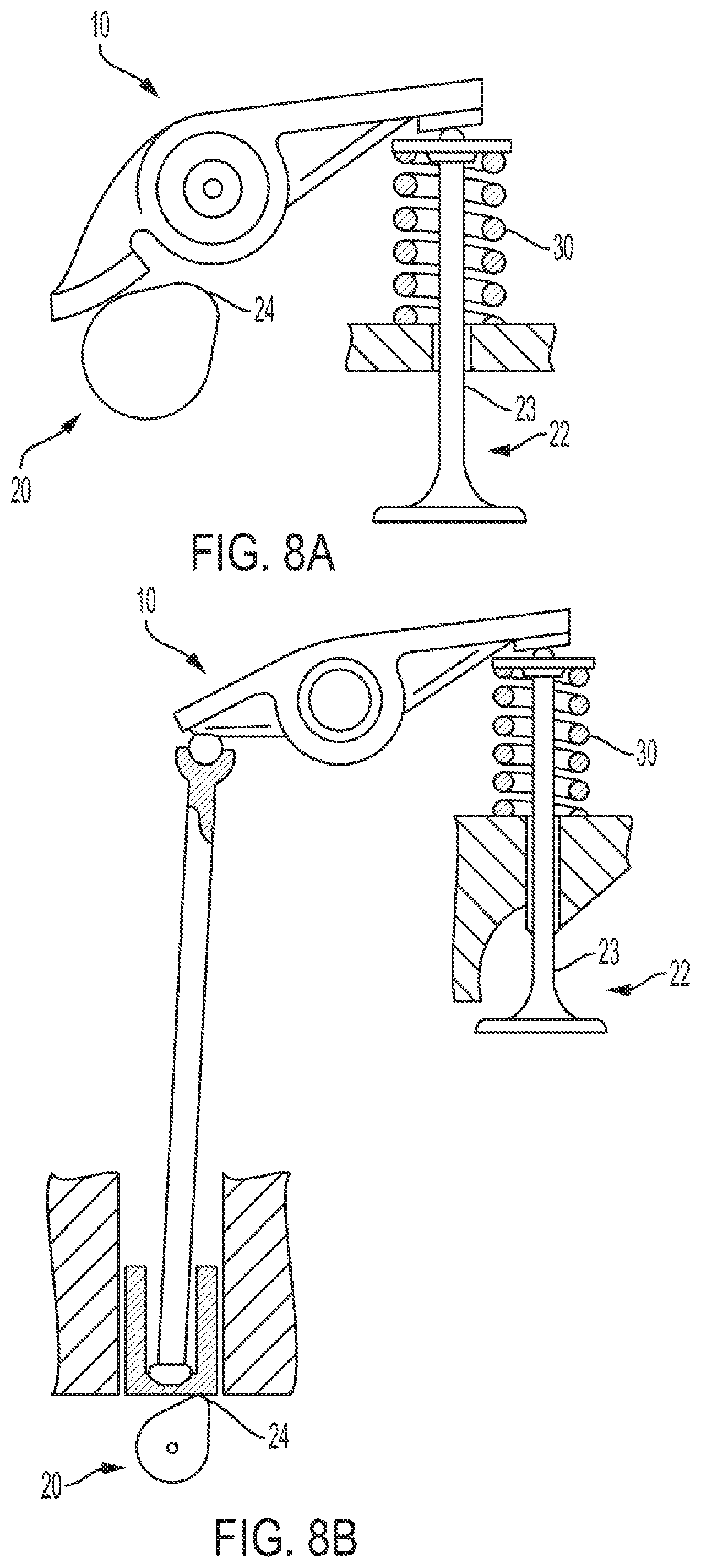
[0003] Referring to FIGS. 8A and 8B, rocker arms 10 are often used in valve trains of an internal combustion engines to transmit motion from a camshaft 20 of the engine to one or more intake or exhaust valves 22. As camshaft 20 rotates, rocker arm 10 receives a direct (FIG. 1A) or indirect (FIG. 1B) force from a corresponding lobe 24 on the camshaft 20 via direct contact with the camshaft 20 (commonly referred to as "Type 3" rocker arm) or contact with a pushrod and lifter (commonly referred to as "Type 5" rocker arm), and transmits the force to valve 22 to open and/or close the valve. The center of the rocker arm 10 is pivotably constrained to the cylinder head so that the second end of the rocker arm 10 moves up and down in a vertical plane. The second end of the rocker arm engages an upper end of a valve stem 23 of the corresponding valve 22, thereby transmitting downward forces to the valve. A spring 30 constantly urges the second end of rocker arm 10 upward.
[0004] Preferably, engine components such as rocker arms exhibit high strength for durability, yet are light weight so that low mass moments of inertia facilitate rapid response of the components at lower force levels, thereby improving the overall efficiency and performance of the engine. As such, there remains a need for rocker arms that exhibit high strength while exhibiting reduced mass moments of inertia as compared to known rocker arms.
[0005] The present invention recognizes and addresses considerations of prior art constructions and methods.
SUMMARY OF THE INVENTION
[0006] One embodiment of the present disclosure provides a rocker arm for use in a valvetrain of a vehicle, having a body portion including two opposed side wall portions, each side wall portion defining a bearing aperture therein, each side wall portion including a bearing boss disposed along a perimeter of the corresponding bearing aperture and extending outwardly from the corresponding side wall portion. A support member has a pair of opposed ends, each opposed end being received in a corresponding bearing aperture, and each bearing boss includes a first portion having a first radial thickness and a second portion having a second radial thicknesses, the first radial thickness being greater than the second radial thickness.
[0007] Another embodiment of the present disclosure provides a rocker arm for use in a valvetrain of a vehicle, having a body portion including two opposed side wall portions, each side wall portion defining a circular bearing aperture therein, each side wall portion including a bearing boss disposed along a perimeter of the corresponding bearing aperture and extending outwardly from the corresponding side wall portion, each bearing boss having a circular outer perimeter, and a support member having a pair of opposed ends, each opposed end being received in a corresponding bearing aperture, wherein each bearing boss includes a first portion having a first radial thickness and a second portion having a second radial thicknesses, the first radial thickness being greater than the second radial thickness.
[0008] The accompanying drawings, which are incorporated in and constitute a part of this specification, illustrate one or more embodiments of the invention and, together with the description, serve to explain the principles of the invention.
BRIEF DESCRIPTION OF THE DRAWINGS
[0009] A full and enabling disclosure of the present invention, including the best mode thereof, directed to one of ordinary skill in the art, is set forth in the specification, which makes reference to the appended drawings, in which;
[0010] FIGS. 1A and 1B are perspective views of a rocker arm in accordance with an embodiment of the present invention;
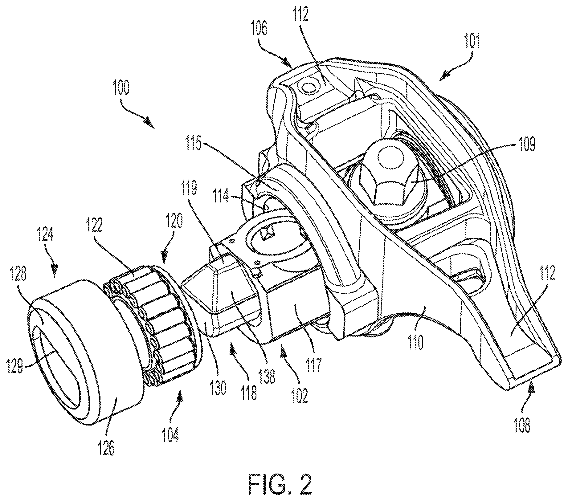
[0011] FIG. 2 is an exploded, perspective view of the rocker arm as shown in FIGS. 1A and 1B;
[0012] FIGS. 3A and 3B are side views of the rocker arm shown in FIGS. 1A and 1B;
[0013] FIG. 4 is a bottom view of the rocker arm shown in FIGS. 1A and 1B;
[0014] FIG. 5 is a top perspective view of the rocker arm shown in FIGS. 1A and 1B;
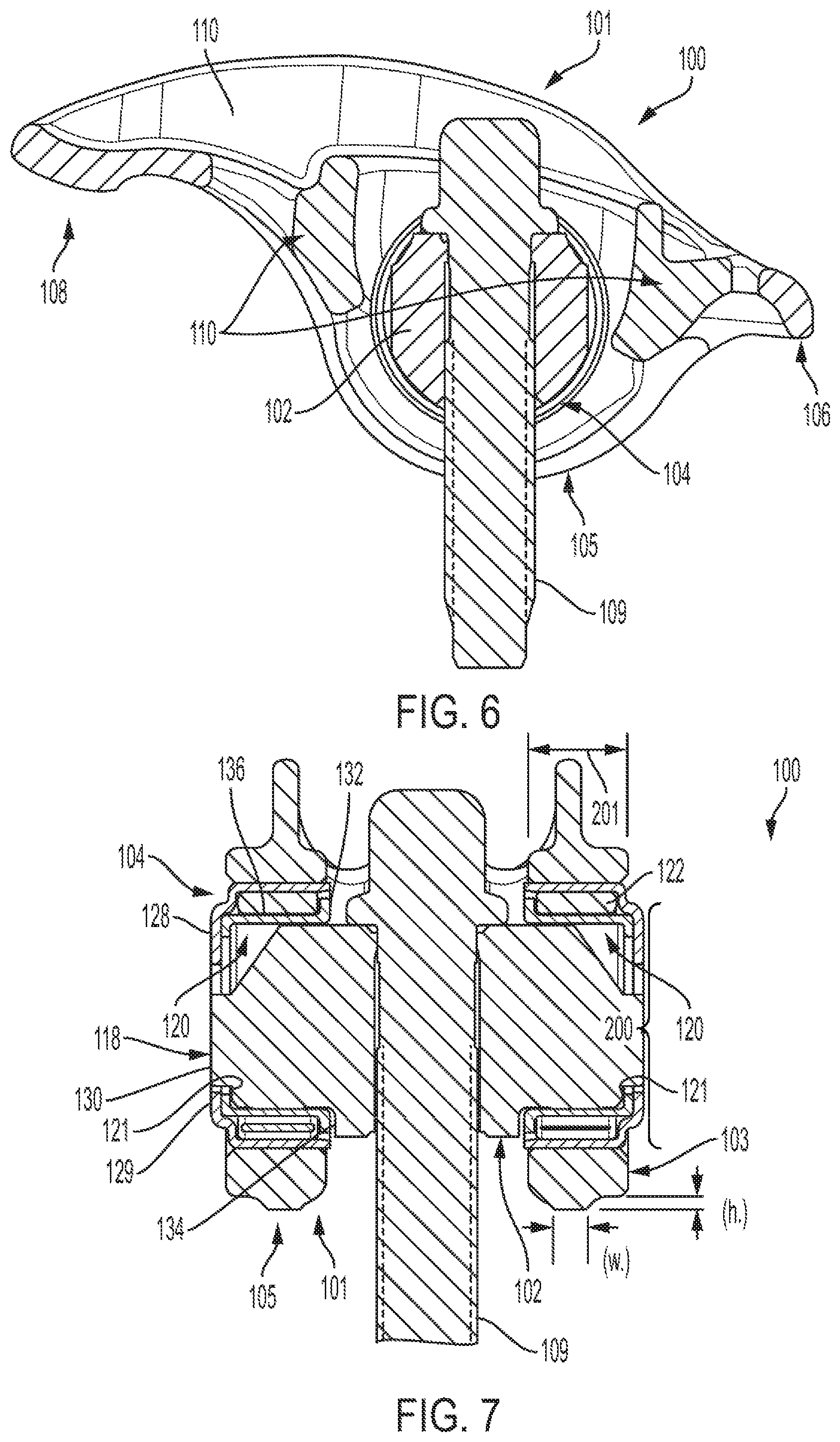
[0015] FIG. 6 is a cross-sectional view of the rocker arm shown in FIG. 4, taken along line 6-6;
[0016] FIG. 7 is a cross-sectional view of the rocker arm as shown in FIG. 3B, taken along line 7-7; and
[0017] FIGS. 8A and 8B are rocker arm assemblies in accordance with the prior art as used in a valve train assembly of an internal combustion engine.
[0018] Repeat use of reference characters in the present specification and drawings is intended to represent same or analogous features or elements of the invention according to the disclosure.
DETAILED DESCRIPTION OF THE PREFERRED EMBODIMENTS
[0019] Reference will now be made in detail to presently preferred embodiments of the invention, one or more examples of which are illustrated in the accompanying drawings. Each example is provided by way of explanation, not limitation, of the invention. In fact, it will be apparent to those skilled in the art that modifications and variations can be made in the present invention without departing from the scope and spirit thereof. For instance, features illustrated or described as part of one embodiment may be used on another embodiment to yield a still further embodiment. Thus, it is intended that the present invention covers such modifications and variations as come within the scope of the appended claims and their equivalents.
[0020] As used herein, terms referring to a direction or a position relative to the orientation of the fuel-fired heating appliance, such as but not limited to "vertical," "horizontal," "upper," "lower," "above," or "below," refer to directions and relative positions with respect to the appliance's orientation in its normal intended operation, as indicated in the Figures herein. Thus, for instance, the terms "vertical" and "upper" refer to the vertical direction and relative upper position in the perspectives of the Figures and should be understood in that context, even with respect to an appliance that may be disposed in a different orientation.
[0021] Further, the term "or" as used in this disclosure and the appended claims is intended to mean an inclusive "or" rather than an exclusive "or." That is, unless specified otherwise, or clear from the context, the phrase "X employs A or B" is intended to mean any of the natural inclusive permutations. That is, the phrase "X employs A or B" is satisfied by any of the following instances: X employs A; X employs B; or X employs both A and B. In addition, the articles "a" and "an" as used in this application and the appended claims should generally be construed to mean "one or more" unless specified otherwise or clear from the context to be directed to a singular form. Throughout the specification and claims, the following terms take at least the meanings explicitly associated herein, unless the context dictates otherwise. The meanings identified below do not necessarily limit the terms, but merely provided illustrative examples for the terms. The meaning of "a," "an," and "the" may include plural references, and the meaning of "in" may include "in" and "on." The phrase "in one embodiment," as used herein does not necessarily refer to the same embodiment, although it may.
[0022] Referring now to the figures, the present disclosure relates to design elements for the manufacture of rocker arms for engine valve trains utilizing an investment casting lost wax process. The discussed features allow the rocker arm 100 to maintain high performance with low mass and mass moment of inertia (MMOI), while including desirable features for the manufacturability/cast-ability of the rocker arm.
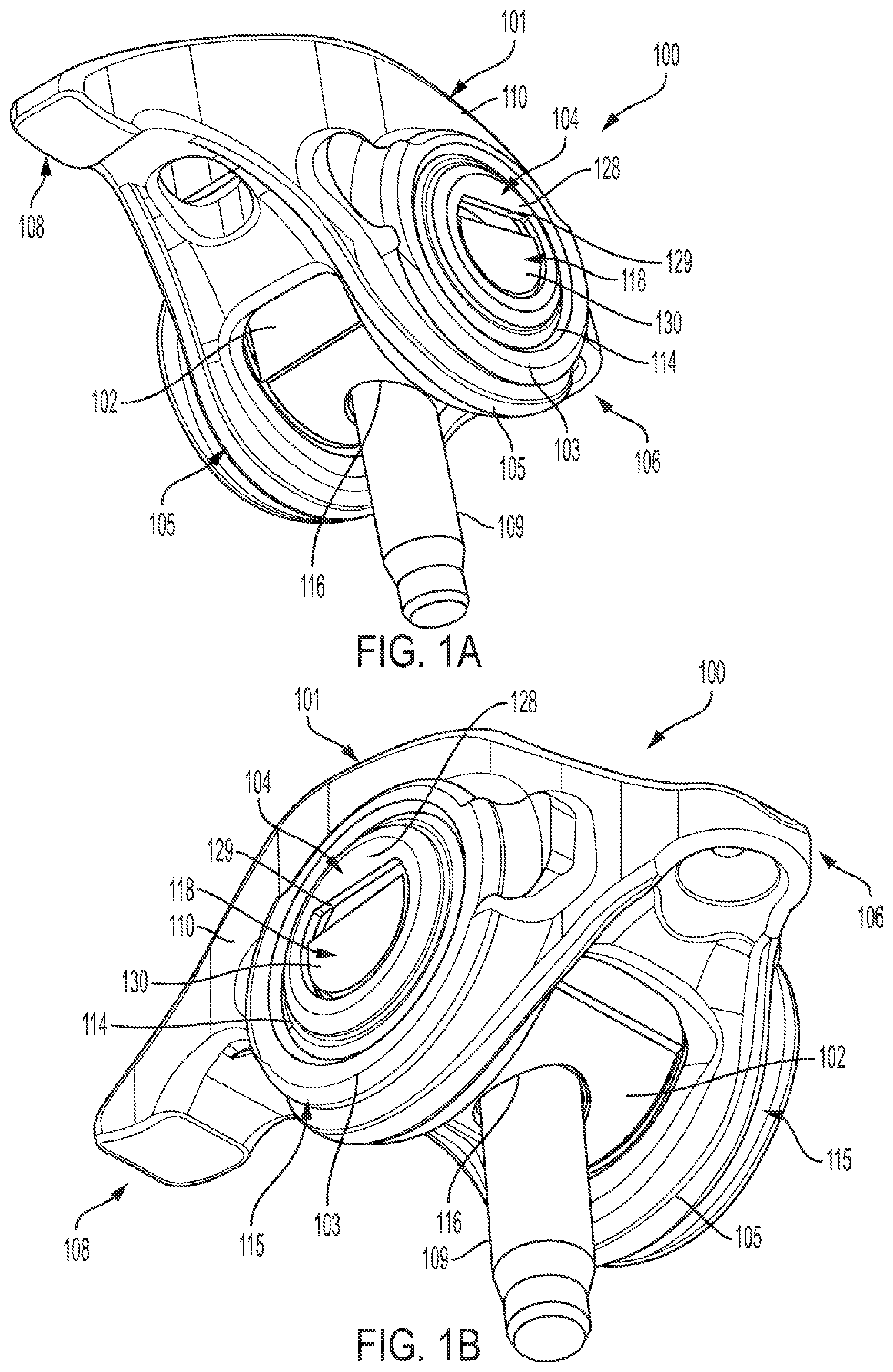
[0023] As shown in FIGS. 1A and 1B, an embodiment of a rocker arm assembly 100 in accordance with the present disclosure includes a rocker arm 101 supported on a rocker arm support member 102 by a pair of radial roller bearings 104 (FIG. 2), as would be used in an internal combustion engine. Rocker arm 101 has a first end 106 for engagement with a hydraulic lash adjuster, not shown, and second end 108 for engagement with a valve stem (23, FIG. 8A) of a poppet valve (20, FIG. 8A). The rocker arm assembly 100 is mounted on the engine by a stud 109, cap screw, or other stud means, not shown. As shown, rocker arm 101 is of a cast configuration including a pair of side walls 110 connected by a pair of end flanges 112, providing added rigidity. Each side wall 110 includes a mounting aperture 114 for receiving a corresponding radial roller bearing 104 therein. Note, however, the rocker arm assembly 100 of the present invention may be employed with cast rocker arms of various configurations.
[0024] Referring additionally to FIGS. 2 and 4, rocker arm support member 102 has a substantially vertical bore 116 for receiving the stud means 109 to mount the rocker arm 101 to the engine. Rocker arm support member 102 has a body portion 117 and a pair of bearing support arms 118 which extend in opposite directions along a common axis perpendicular to the stud means. Radial roller bearings 104 are mounted along that axis over support arms 118 by inner bearing sleeves 120 which provide inner raceways for roller members 122. As shown, a top surface 119 of each bearing support arm 118 is flat and side surfaces 138 are angled so that oil may flow between the inner cylindrical surface of the corresponding inner sleeve 120 and the bearing support arm 118. Roller bearings 104 may employ a full complement of needle rollers 122, as illustrated, or may employ other types of roller members, with or without retainers. Roller members 122 are within an annulus formed between inner sleeves 120 and outer bearing cups 124. Outer bearing cups 124 have a common axis and are rigidly mounted in the two spaced apart side walls 110 of rocker arm 101 by any of various fixing means. In the embodiment shown, for example, mounting apertures 114 formed in the side walls 110 of rocker arm 101 provide an interference fit with bearing cups 124. Rocker arm support member 102 has a cross-section smaller than the mounting apertures 114 in the side walls 110 of rocker arm 101, thus allowing rocker arm support member 102 to be inserted through one of the apertures during assembly, as best seen in FIG. 2.
[0025] As shown, outer bearing cups 124 are of the "open" type. That is, each bearing cup has a cylindrical side wall 126, and a top wall 128 that is perpendicular thereto and defines an aperture 129 therein. As best seen in FIG. 7, the inner surface of top wall 128 is engageable with ends of roller members 122 to limit outward axial movement of the roller members, and the outer surface of the side wall 126 is received in the corresponding mounting aperture 114 in an interference fit. Additionally, as best seen in FIG. 7, an inwardly depending annular flange 121 on the outermost end of each inner bearing sleeve 120 abuts an outer end of the corresponding bearing support arm 118 so that each radial roller bearing 104 is properly positioned within rocker arm 101. As well, the outermost end of each bearing support arm 118 extends outwardly through the aperture 129 of the top wall 128 of the corresponding outer cup 124. In alternate embodiments, top wall 128 of outer cup 124 may be spaced from the end surface 130 of bearing support arm 118 to allow for enhanced flow of lubrication. Preferably, inner sleeves 120 and outer cups 124 are formed by a drawing process.
[0026] Referring again to FIG. 7, inner bearing sleeves 120 are formed with outwardly extending flanges 132 that are engageable with the ends of roller members 122 to limit inward axial movement of the rollers. As well, outwardly extending flanges 132 abut planar surfaces 134 of rocker arm support member 102 to insure proper axial location of inner bearing sleeves 120. A cylindrical wall 136 of each inner bearing sleeve 120 provides an inner raceway for roller members 122 and facilitates use of powder metal forming of rocker arm support member 102 by allowing bearing support arms 118 to have a non-cylindrical configuration, as shown below. Note, however, in alternate embodiments each bearing support arm may have a circular cross-section.
[0027] As best seen in FIG. 2, rocker arm support member 102 may include beveled surfaces 138 and flat side surfaces 140. The beveled and flat surfaces facilitate manufacture of rocker arm support member 102 by powder metal forming. Because roller members 122 ride on inner raceways provided by inner sleeves 120, and because the greatest force from the rocker arm 101 is on the lower portions of roller bearings 104, those beveled and flat surfaces on the top and side portions of bearing support arms 118 of rocker arm support member 102 do not affect operation of the rocker arm assembly.
[0028] Referring to FIGS. 3A and 3B, a preferred embodiment of rocker arm 100 includes a bearing boss 115 formed around each mounting aperture 114, each of which is configured to receive a corresponding bearing 104, wherein material used to form each bearing boss 115 is concentrated toward the bottom portion 103 of the bearing boss 115. Material is concentrated toward the bottom portion 103 of each bearing boss 115 since the bottom portion is the area where the load from the corresponding radial bearing 104, about which the rocker arm 101 pivots, is concentrated on the casting. Traditional rocker arm designs maintain the walls of this feature axisymmetric about the bearing and bearing aperture, and therefore waste mass and increases mass mount of inertia (MMOI) with excess material where it is not required. As shown, although the outer perimeter of the bearing boss 115 is circular, the bearing boss is not concentric to the circular bearing aperture 114, i.e., the longitudinal center axis of the bearing aperture 114 is not collinear with the longitudinal center axis of the bearing boss 115. As well, preferably, the width of the bearing boss 115 in the radial direction is least at its top portion, and increases gradually until reaching its maximum radial thickness at the bottom portion 103 of the bearing boss 115. As best in FIGS. 5 and 6, the top profile of the rocker arm 101 is scalloped on the camshaft acting end 108 of the rocker arm 101 to lower MMOI and increase performance in responsiveness. As well, as shown in FIGS. 1A, 1B, and 4, strengthening ribs 105 added to the bottom of each side wall 100 of the rocker arm 101 improve the fatigue strength of the rocker arm 101 while minimizing impact on MMOI or cast-ability.
[0029] Referring again to FIG. 7, preferably, the strengthening ribs 105 extend the full length of the rocker arm from the cam acting end 106 to the valve actuation end 108. The sizing of each strengthening rib 105 is preferably optimized so that its width (w.sub.1) is 25-50% of the width of the corresponding bearing hoop 201. The height (h.sub.1) of each rib 105 is preferably selected to be 25-50% the rib width (w.sub.1) on the bottom of the bearing boss section 103. The rib height (h.sub.2) increases to 40-60% of the section height as it extends to the valve actuating end 108 of the rocker arm 101. The rib height increases to 80-120% of section thickness as it extends to the cam acting end of the rocker arm. These proportions maximize the performance potential of the rocker arm without compromising the manufacturability of the part for the casting process. Note, however, other proportions are utilized in alternate embodiments of the present invention.
[0030] Referring now to FIGS. 4 and 5, side view and a cross-sectional view through the centerline of the rocker arm 101 shows gates 110 aligned with thick sections through the center of the part to protect metal flow during casting, but hold the sections tight to the center of rotation to minimize MMOI. FIGS. 6 and 7 provide views of the strengthening ribs and their placement on the rocker arm 101.
[0031] While one or more preferred embodiments of the invention are described above, it should be appreciated by those skilled in the art that various modifications and variations can be made in the present invention without departing from the scope and spirit thereof. It is intended that the present invention cover such modifications and variations as come within the scope and spirit of the appended claims and their equivalents.
* * * * *
D00000
D00001
D00002
D00003
D00004
D00005
D00006
XML
uspto.report is an independent third-party trademark research tool that is not affiliated, endorsed, or sponsored by the United States Patent and Trademark Office (USPTO) or any other governmental organization. The information provided by uspto.report is based on publicly available data at the time of writing and is intended for informational purposes only.
While we strive to provide accurate and up-to-date information, we do not guarantee the accuracy, completeness, reliability, or suitability of the information displayed on this site. The use of this site is at your own risk. Any reliance you place on such information is therefore strictly at your own risk.
All official trademark data, including owner information, should be verified by visiting the official USPTO website at www.uspto.gov. This site is not intended to replace professional legal advice and should not be used as a substitute for consulting with a legal professional who is knowledgeable about trademark law.