Downhole anchoring device
Grindhaug; Gaute ; et al.
U.S. patent application number 16/961453 was filed with the patent office on 2021-03-18 for downhole anchoring device. The applicant listed for this patent is Equinor Energy AS. Invention is credited to Bjorn Torstein Bruun, Gaute Grindhaug.
| Application Number | 20210079747 16/961453 |
| Document ID | / |
| Family ID | 1000005254026 |
| Filed Date | 2021-03-18 |


| United States Patent Application | 20210079747 |
| Kind Code | A1 |
| Grindhaug; Gaute ; et al. | March 18, 2021 |
Downhole anchoring device
Abstract
There is disclosed an apparatus for axially anchoring a tool downhole in a well casing, the apparatus comprising: an anchor configured to be disposed in, and actuatably and rotatably engaged with, the casing; and a rotatable tool being configured to be disposed within the casing; whereby the anchor, when rotatably engaged with the casing, prevents movement of the rotatable tool in the axial direction A whilst allowing for rotation of the tool about the axial direction. A corresponding method of anchoring a tool downhole is also disclosed.
| Inventors: | Grindhaug; Gaute; (Stavanger, NO) ; Bruun; Bjorn Torstein; (Stavanger, NO) | ||||||||||
| Applicant: |
|
||||||||||
|---|---|---|---|---|---|---|---|---|---|---|---|
| Family ID: | 1000005254026 | ||||||||||
| Appl. No.: | 16/961453 | ||||||||||
| Filed: | January 11, 2019 | ||||||||||
| PCT Filed: | January 11, 2019 | ||||||||||
| PCT NO: | PCT/NO2019/050004 | ||||||||||
| 371 Date: | July 10, 2020 |
| Current U.S. Class: | 1/1 |
| Current CPC Class: | E21B 23/0415 20200501; E21B 29/005 20130101; E21B 23/0411 20200501 |
| International Class: | E21B 23/04 20060101 E21B023/04; E21B 29/00 20060101 E21B029/00 |
Foreign Application Data
| Date | Code | Application Number |
|---|---|---|
| Jan 11, 2018 | GB | 1800475.4 |
Claims
1. An apparatus for axially anchoring a tool downhole in a well casing, the apparatus comprising: an anchor configured to be disposed in, and actuatably and rotatably engaged with, the casing; and a rotatable tool being configured to be disposed within the casing; whereby the anchor, when rotatably engaged with the casing, prevents movement of the rotatable tool in the axial direction whilst allowing for rotation of the tool about the axial direction.
2. The apparatus of claim 1, wherein the rotatable tool is connected below the anchor in the axial direction.
3. The apparatus of claim 1 or 2, wherein the anchor and the rotatable tool are rotationally locked to one another.
4. The apparatus of any preceding claim, wherein the anchor is arranged to be actuated into rotatable engagement with the casing by a fluid, preferably drilling mud.
5. The apparatus of any preceding claim, wherein the anchor comprises a substantially hollow body.
6. The apparatus of any preceding claim, wherein the anchor comprises a plurality of extendable casing engagement blocks.
7. The apparatus of claim 6, wherein the blocks are actuatable from a retracted position in which the blocks are substantially housed within the body to an actuated position in which the blocks extend radially from the body.
8. The apparatus of claim 6 or 7, wherein the plurality of blocks are disposed circumferentially around the anchor in at least one plane perpendicular to the axial direction, each plane comprising at least two blocks.
9. The apparatus of any of claims 6 to 8, wherein the plurality of blocks are disposed in more than one plane perpendicular to the axial direction, and preferably in at least two planes perpendicular to the axial direction.
10. The apparatus of any of claims 7 to 9, wherein the blocks are biased towards the retracted position.
11. The apparatus of any of claims 7 to 10, wherein the body comprises at least one opening through which the plurality of blocks extends through in the actuated position.
12. The apparatus of claim 11, wherein a plurality of openings is provided, and wherein there is preferably one opening for every block of the plurality of blocks.
13. The apparatus of any of claims 6 to 12, wherein the blocks comprise at least one engagement wheel rotatably mounted thereto in a plane perpendicular to the axial direction, the at least one wheel being configured to rotatably engage with the inner surface of the casing.
14. The apparatus of claim 13, wherein each of the at least one wheels on each of the plurality of blocks has a knife-edge circumference arranged to cut into the surface of the casing.
15. The apparatus of claim 13 or 14, wherein each of the at least one wheels on each of the plurality of blocks has a circular outer circumference.
16. The apparatus of claims 13 to 15, wherein each of the wheels is formed of high carbon steel or tungsten carbide.
17. The apparatus of any of claims 13 to 16, wherein the engagement of the wheels with the casing forms a groove in the casing, whereby the wheel may freely rotate against the casing in a plane of the groove whilst preventing movement of the wheels in the axial direction.
18. The apparatus of any of claims 13 to 17, wherein a wheel on each of the plurality of blocks is axially aligned with at least one other wheel on another block.
19. The apparatus of any preceding claim, wherein the rotatable tool is a casing cutter for cutting through the casing.
20. The apparatus of claim 19, wherein the casing cutter comprises a plurality of blades, the blades being hydraulically actuatable into contact with the casing.
21. The apparatus of claim 20, wherein the blades comprise high carbon steel, or tungsten carbide.
22. A drillstring comprising the apparatus of any preceding claim, wherein the drillstring extends downwardly from a rig or vessel, and wherein rotation of the drillstring drives the apparatus into simultaneous rotation.
23. The drillstring of claim 22, configured to allow fluid to pass down therethrough to engage the apparatus.
24. The drillstring of claim 22 or 23, further comprising a length compensating device (LCD) disposed above the apparatus in the axial direction.
25. The drillstring of claim 24, wherein the LCD is a bumper sub.
26. The drillstring of claim 24 or 25, further comprising a controller associated with the LCD, the controller being configured to alter the length of the LCD.
27. The drillstring of any of claims 22 to 26, wherein the drillstring is connected to a surface heave compensator disposed at the rig or vessel.
28. A method of anchoring a tool downhole within a casing of a subsea oil well comprising the steps of: providing: a drillstring extending downwardly from a rig or vessel; an actuatable anchor rotatably mounted on the drillstring; and a rotatable tool disposed on the drillstring; locating the tool in a desired position downhole within the casing; actuating the anchor into rotatable engagement with the casing; and actuating the tool; whereby the anchor prevents axial movement of the actuated tool.
29. The method as claimed in claim 28, wherein the tool is a casing cutter.
30. The method as claimed in claim 29, further comprising extending the casing cutter into rotational contact with the casing whilst allowing the casing cutter to rotate about the axial direction so as to cut through a depth of the casing.
31. A method of cutting a casing of a subsea oil well comprising the steps of: providing the drillstring of any of claims 22 to 27; lowering the drillstring from the rig or vessel to align the anchor and the casing cutter in a desired position within the casing; and passing a fluid down the drillstring to activate the anchor and the casing cutter, wherein, the fluid actuates the anchor into rotatable engagement with the casing and the casing cutter into contact with the casing such that the anchor prevents movement of the casing cutter in the axial direction whilst allowing the casing cutter to rotate about the axial direction to cut through a depth of the casing in a radial plane perpendicular to the axial direction.
32. The method of claim 31, further comprising the use of a length compensation device controlled by a controller.
33. An apparatus for cutting a casing of a subsea oil well, the apparatus comprising: a drillstring extending downwardly from a rig or vessel; an anchor rotatably mounted on the drillstring and configured to be disposed in, and rotatably and actuatably engaged with, the casing; and a rotatable casing cutter disposed on the drillstring and configured to be disposed within and cut through the casing; whereby the anchor, when rotatably engaged with the casing, prevents movement of the casing cutter in the axial direction whilst allowing for rotation of the casing cutter about the axial direction.
Description
[0001] The present invention relates to an apparatus and method for preventing axial motion of a subsea tool caused by heave felt at the rig or vessel from which the apparatus extends, and in particular to preventing axial motion of a casing cutter caused by heave to allow for improved casing cutting. The apparatus and method are also applicable to other subsea tools and operations where relative axial motion of the tool and well structure should be avoided.
[0002] In the oil and gas industry it is commonplace to carry out subsea, downhole operations and/or cutting or otherwise machining of subsea components using a tool attached to a distal end of a drillstring, the drillstring extending from a rig or vessel at sea level.
[0003] For instance, the use of a drillstring, having a cutting element disposed thereon, to cut and manipulate a subsea well casing or other component that is disposed below the seabed, is commonplace.
[0004] One such category of downhole operations that typically employ the above combination of a drillstring and cutting element are plug and abandonment (P&A) operations. An exemplary P&A operation is depicted in FIGS. 5A-5D, in which a distal portion 110 of a drillstring 104 is deployed downhole in a subsea casing 105 in order to cut said casing 105, specifically an inner casing 105a positioned within an outer casing 105b in the depicted example, using a hydraulically actuated casing cutter 111.
[0005] As seen in FIG. 5B, the drillstring 104 is rotated, which in turn rotates the casing cutter 111. The casing cutter 111 is hydraulically actuated to engage with the inner casing 105a and, due to its rotation, cuts through the inner casing 105a. This enables removal of a section 105c of said inner casing 105a as shown in FIGS. 5C and 5D. After the inner casing 105a or the section 105c of the inner casing 105a is removed, the remaining part of casing 105a is then plugged, usually with cement.
[0006] Similarly and as equally represented by FIGS. 5A-5D, slot recovery operations employ a casing cutter 111 incorporated on a drillstring 104 to remove a section 105c of a casing 105 (an inner casing 105a in the example depicted) from a non-producing, plugged well within a slot. Following the removal of such a section, a new wellbore is typically sidetracked from the existing well to allow for the continued recovery of resources from the previously non-producing slot. The slot production lifetime is thus extended through the recovery of resources from the new, sidetracked wellbore.
[0007] A requirement for the successful cutting of the casing that occurs in both slot recovery and P&A operations is a steady drillstring as there needs to be little, or no, axial displacement of the cutting element in order to provide a successful cut of the casing. Indeed, in many downhole operations, as well as the cutting operations discussed above, it is often a requirement that there is little or no axial displacement of the relevant downhole tool to ensure successful completion of the operation. As such, clear operational limits for slot recovery, P&A, and other downhole operations exist due to the effects of heave felt by the rig or vessel at sea level caused by surface waves. As a result, operation may be delayed significantly because of poor sea conditions.
[0008] The movement of the rig or vessel can be accommodated to some extent by flexing or stretching of the drillstring on which the downhole tool is disposed. However, to further counteract the motion of the rig or vessel that the drillstring extends from, it is known to employ surface heave compensators disposed on the rig or vessel. These surface heave compensators counteract the up-and-down motion experienced by the drillstring due to motion of the rig or vessel by providing a temporary displacement in the drillstring to counterbalance this upward or downward motion. The aim of the surface heave compensators is to keep the position of the drillstring, and hence the downhole tool, constant in an axial direction. In the exemplary P&A and slot recovery operations discussed above, keeping the cutting element 111 in a constant position in the axial direction ensures that a cut can be successfully performed, smoothly and in a single plane perpendicular to the axis of the casing 105.
[0009] However, surface heave compensators have only been found to be partly effective and they are unable to completely negate axial displacement experienced by the downhole tool due to the effects of heave felt at the surface, particularly in severe weather conditions. Moreover, the length compensation provided to the downhole tool by the surface heave compensator has been proven to be imprecise, often over-shooting or under-shooting the required length compensation that is required to keep the downhole tool steady. Thus, there are often long waiting times associated with downhole operations (e.g. both P&A and slot recovery operations where a precise cut is required) whilst the rig or vessel experiences high degrees of heave, especially in the autumn and winter seasons.
[0010] It is also known to provide a second length compensating device, similar in functionality to the surface heave compensator, elsewhere along the length of the drillstring in order to try and further counteract the effects of heave, such as a bumper sub, an accelerator or an intensifier. However, these additional length compensating devices typically only provide partial improvements to both precision and effectiveness due to their limited stroke. As such, drillstrings that make use of both a surface heave compensator and an additional length compensating device are still unable to completely negate the axial displacement experienced by the downhole tool due to the effects of heave felt at the surface.
[0011] U.S. Pat. No. 2,534,858 discloses a device adapted to be lowered into a casing within a well bore for the purpose of severing and removing a portion of the casing from the well. The device comprises a cutter assembly and an anchor assembly. The anchor assembly comprises an anchor casing that house slips and blocks which are adapted to be expanded radially outwardly through openings or from recesses in the anchor casing. Once expanded radially outwardly, the slips and blocks of the anchor assembly frictionally engage with the casing so as to prevent rotation of the anchor assembly relative to the casing, similar in action to a drum brake, whilst also preventing axial movement of the anchor assembly. The cutter assembly of the device is axially connected to the anchor assembly and, by virtue of a bearing, is able to rotate relative to the anchor assembly. During a cutting operation, the slips and blocks of the anchor assembly engage with the casing so as to prevent any axial and rotational movement of the anchor assembly relative to the casing, whilst the cutter assembly rotates about the axial direction so as to cut through the casing. The connection between the cutter assembly and the anchor assembly allows for the relative rotation between the two to ensure that a cut of the casing may be produced, whilst it also ensures that axial movement of the cutter assembly during the cutting operation is prevented by virtue of the frictional engagement between the slips/blocks and the casing.
[0012] The device of U.S. Pat. No. 2,534,858 provides an improvement in negating axial displacement of a downhole tool (cutter assembly) during operation as compared to those other devices discussed above. However, the solution proposed in U.S. Pat. No. 2,534,858 is mechanically complex, not least because it requires two separate downhole assemblies to be rotatably connected with one another via a bearing mechanism.
[0013] According to the invention, there is provided an apparatus for axially anchoring a tool downhole in a well casing, the apparatus comprising: an anchor configured to be disposed in, and actuatably and rotatably engaged with, the casing; and a rotatable tool configured to be disposed within the casing; whereby the anchor, when rotatably engaged with the casing, prevents movement of the rotatable tool in the axial direction whilst allowing for rotation of the tool about the axial direction.
[0014] Thus, by means of the invention, the tool is held in the desired position in the axial direction by the anchor so that it may perform its function effectively and precisely. Furthermore, where a drillstring is potentially affected by heave of a surface vessel, this may be accommodated in the known manner by flexing/stretching of the drillstring and/or by means of heave compensators, or similar devices, whilst the anchor ensures that the tool remains in its desired axial location. Moreover, since the anchor is disposed within the casing in a rotatable manner, the apparatus may be used to anchor rotatable tools without the need for additional bearing mechanisms. Thus, it will appreciated be that the apparatus of the present invention provides a mechanically simpler, and thus potentially more reliable means for negating axial displacement of a downhole tool during operation than the device disclosed in U.S. Pat. No. 2,534,858.
[0015] Both the rotatable tool and the anchor of the invention are positioned on the apparatus along the axial direction, and it is preferable that the rotatable tool is connected below the anchor in the axial direction.
[0016] Although the invention is useful in connection with any rotary tool, and in particular any downhole rotary tool, that needs to be retained in a given axial position, it is particularly useful in the context of casing cutting operations and so the tool is preferably a casing cutter.
[0017] As noted above, the anchor is arranged to rotate with the drillstring relative to the casing, whilst axially anchored thereto, and so it and the rotatable tool may be rotationally locked to one another. However, the anchor and the rotatable tool may be arranged such that the tool rotates relative to the anchor or relative to a part of it, e.g. so that the tool may rotate at a different speed to the drillstring.
[0018] Any suitable mechanism may be used to actuate the engagement of the anchor--e.g. where electrical power is available solenoid(s) may be used. However, the anchor is preferably arranged to be actuated into engagement with the casing by a fluid, which will typically be drilling fluid ("mud") since it is conventional for a flow of drilling mud to be provided from a platform or surface vessel via a drillstring to downhole tools. For example, drilling mud-driven hydraulic actuators may be used. Likewise, whilst the tool may be driven by an electric motor, or simply, and preferably, driven by the rotation of the drill string, it is optionally caused to rotate by the fluid, e.g. by means of a drilling mud-driven hydraulic motor. Furthermore, it is convenient to arrange this so that the tool is driven simultaneously with the actuation of the anchor.
[0019] In order to allow the anchor to engage with the casing, it will typically comprise an expandable engagement system. A convenient arrangement is for the anchor to comprise a (e.g. substantially hollow) body housing a plurality of extendable casing engagement members, referred to here as blocks. Thus, these blocks may be actuatable from a retracted position in which the blocks are substantially within the body to an actuated position in which the blocks extend radially from the body. Suitable openings in the body may be provided through which the blocks may extend into the actuated position.
[0020] In order to ensure sound engagement and to enable the apparatus to rotate, the blocks are preferably disposed circumferentially around the anchor in at least one plane perpendicular to the axial direction, with each plane comprising at least two blocks. However, preferably at least three or more blocks are provided in each plane to distribute the loads more widely.
[0021] Indeed, in applications where the anchor has to deal with significant axial loading, the plurality of blocks are preferably disposed in more than one plane perpendicular to the axial direction and preferably in two or three such planes.
[0022] Whilst the blocks may be configured to require positive actuation and retraction, in order to simplify design and to ensure that the drillstring may be recovered in the event of a loss of fluid communication or other failure, the blocks are biased towards the retracted position. Thus, cessation of the flow of drilling mud will result in retraction of the blocks under the bias force and hence deactivation of the anchor.
[0023] It is preferable that the blocks have rotary engagement means, which may also act as a bearing (i.e. similarly to a roller bearing). Thus, preferably they each comprise at least one engagement wheel rotatably mounted thereto. Such wheels are most preferably arranged in a plane perpendicular to the axial direction. The wheels may then be configured to engage with the inner surface of the casing when the blocks are in the actuated position.
[0024] Whilst in some cases sufficient purchase on the casing to anchor the apparatus may be provided by frictional engagement, it is preferred that the rotary engagement means on each of the plurality of blocks is a wheel arranged to cut into the surface of the casing, e.g. by having knife-edge circumference. Such an arrangement obviously requires the engagement surface of the wheels to be harder than the casing. Accordingly, each of the wheels may be formed of high carbon steel or comprise tungsten carbide elements.
[0025] The wheels may have any suitable circumferential geometry that allows for rotation of the anchor, and that ensures the casing is sufficiently cut into. For instance, the outer circumference of the wheel may be elliptical, triangular, star-shaped, or indeed any suitable geometrical shape. However, it is preferred that the wheels have a circular outer circumference to provide uniformity to both the rotation of the anchor and the cut imprinted into the casing.
[0026] Thus, the engagement of the wheels with the casing may form a groove in the casing within which they may then run, whereby the wheels may freely rotate against the casing in a plane of the groove, whilst preventing movement of the wheels in the axial direction because of their engagement in the groove.
[0027] Where multiple blocks are provided, a wheel on each of the plurality of blocks may conveniently be axially aligned with at least one other wheel on another block.
[0028] As discussed above, the rotatable tool may be a casing cutter for cutting through the casing. Any cutter suitable for cutting through a depth of the casing may be used, for instance laser cutters or abrasive cutters. However, it is preferred that the casing cutter is a mechanical cutter comprising a blade, preferably a plurality of blades. Like the other active components of the apparatus, the blades may be extended radially outwardly hydraulically, e.g. by drilling fluid. Thus, the flow of the fluid may result in the blades extending into contact with the casing.
[0029] As is known in the art, the casing cutter blades should be harder than the casing itself and so the blades may be formed, for example, from a high carbon steel or tungsten carbide.
[0030] Viewed from another aspect of the invention, there is provided an apparatus for axially anchoring a tool downhole in a well casing, the apparatus comprising: an anchor configured to be rotatably disposed in, and actuatably engaged with, the casing; and a rotatable tool being configured to be disposed within the casing; whereby the anchor, when engaged with the casing, prevents movement of the rotatable tool in the axial direction whilst allowing for rotation of the tool about the axial direction.
[0031] The apparatus of this further aspect may employ any of the features outlined above in relation to the first aspect of the invention.
[0032] The apparatuses of the above aspects are intended for use in combination with a drillstring and so, viewed from another aspect, there is provided a drillstring comprising an apparatus as described above, wherein the drillstring extends downwardly from a rig or vessel. As is well known in the art, the drillstring may be configured to permit drilling fluid ("mud") to pass down therethrough to engage the apparatus.
[0033] Since a particularly useful application of the invention is in the context of casing cutting, another aspect of the invention provides an apparatus for cutting a casing of a subsea oil well, the apparatus comprising: a drillstring extending downwardly from a rig or vessel; an anchor rotatably mounted on the drillstring and configured to be disposed in and actuatably and rotatably engaged with the casing; and a rotatable casing cutter disposed on the drillstring and configured to be disposed within and cut through the casing; whereby the anchor, when rotatably engaged with the casing, prevents movement of the casing cutter in the axial direction whilst allowing for rotation of the casing cutter about the axial direction.
[0034] Whilst a certain degree of heave may be accommodated by the bend and/or stretch of the drillstring (particularly in the case of long drillstrings), preferably the drillstring further comprises a length-compensating device (LCD). This may be a bumper sub, an accelerator or an intensifier. The LCD can form part of the apparatus, though it is preferably disposed above the apparatus in the axial direction. The system may further comprise a controller associated with the LCD, the controller being configured to alter the length of the LCD to compensate for heave of the surface vessel or platform and/or allow for precise placement of the casing cutter in the axial direction. In addition, the drillstring may be connected to a surface heave compensator disposed at the rig or vessel.
[0035] The invention also extends to a corresponding method and thus, viewed from another aspect, there is provided a method of anchoring a tool downhole within a subsea casing comprising the steps of providing: a drillstring extending from a rig or vessel toward the seabed; an actuatable anchor rotatably mounted on the drillstring; and a rotatable tool disposed on the drillstring; locating the tool in a desired position downhole within the casing; actuating the anchor into rotatable engagement with the casing; and actuating the tool; whereby the anchor prevents axial movement of the actuated tool.
[0036] The method preferably comprises the use of the apparatus (and particularly its preferred forms) described above. Thus, for example, the tool may be a casing cutter.
[0037] In such a case, the method may further comprise extending the casing cutter into rotational contact with the casing whilst allowing the casing cutter to rotate about the axial direction so as to cut through a depth of the casing.
[0038] The method preferably comprises the steps of: lowering the drillstring from the rig or vessel to align the anchor and the casing cutter in a desired position within the casing; and passing a fluid down the drillstring to activate the anchor and the casing cutter; wherein the fluid actuates the anchor into rotatable engagement with the casing and the casing cutter into rotational contact with the casing such that the anchor prevents movement of the casing cutter in the axial direction whilst allowing the casing cutter to rotate about the axial direction to cut through a depth of the casing in a radial plane perpendicular to the axial direction.
[0039] As previously described, the method may further comprise the use of a length compensation device controlled by a controller.
[0040] Certain embodiments of the present invention will now be described, by way of example only, and with reference to the accompanying drawings in which:
[0041] FIG. 1 is a schematic view of a rig or vessel carrying out an exemplary downhole operation in a subsea well;
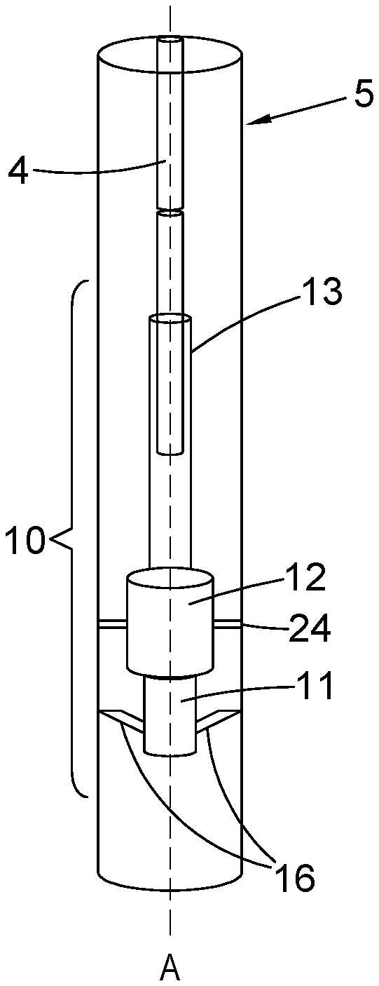
[0042] FIG. 2 is an enlarged schematic view of a distal end portion of a drillstring, disposed within a casing of a subsea well, that incorporates an anchor of a first embodiment used in a P&A or slot recovery operation;
[0043] FIG. 3 shows a close up view of an embodiment of an anchor disposed on the drillstring;
[0044] FIG. 4 shows a close up view of another embodiment of the anchor disposed on the drillstring;
[0045] FIGS. 5A-5D are sequential enlarged schematic views of a distal end portion of a drillstring during the various stages involved in cutting of a casing in a P&A or slot recovery operation as is known from the prior art.
[0046] FIG. 1 illustrates a floating rig or vessel 3 carrying out a downhole operation. Specifically, FIG. 1 depicts a cutting process on a casing 5 of a subsea well that is typically done in a P&A or slot recovery operation. The rig or vessel 3 is positioned at sea level 1 in a position that is approximately axially aligned with the casing 5 extending from the seabed 2. A drillstring 4 extends down from the rig or vessel 3 to the casing 5 and is partly received within a casing 5 of the subsea well, such that the distal end portion 10 is disposed hundreds of metres downhole within the casing 5 (see FIG. 2). The distal end portion 10 is the portion of the drillstring predominantly responsible for cutting the casing 5 and will be described further below with reference to FIGS. 2-4.
[0047] It can clearly be seen in FIG. 1 how the effects of heave at the rig or vessel 3 due to surface waves would lead to an axial displacement of the drillstring 4. In FIG. 1 the surface of the sea 1 is depicted as level and, at the particular moment in time depicted in FIG. 1, there is no requirement for any length compensation to be provided to the distal end portion 10 of the drillstring 4. However, a surface heave compensator (not shown) is provided at the rig or vessel 3 to counteract some of the potential axial displacement of the drillstring 4 that may be caused by the heave of the rig or vessel 3. The remainder of the length compensation that is required to counteract the potential effects of heave felt by the drillstring 4 is provided by flexing or stretching of the drillstring 4 and/or elements contained in the distal end portion 10, which are described in more detail below.
[0048] Turning now to FIG. 2, the distal end portion 10 of the drillstring 4 of FIG. 1 is shown. The distal end portion 10 is disposed downhole within a section of the casing 5. The distal end portion 10 comprises a casing cutter 11, an anchor 12 and a length-compensating device (LCD) 13.
[0049] The LCD 13 is located above the anchor 12 and the casing cutter 11 on the drillstring 4 and it provides length compensation to both the anchor 12 and the casing cutter 11 such that when the drillstring 4 is caused to move upward in an axial direction A due to the effects of heave felt by the rig or vessel 3 at the surface, the LCD 13 extends in length along the axial direction A so that the anchor 12 and the casing cutter 11 experience no, or very little, displacement in the axial direction A. Following any upward motion of the rig or vessel 3 along the axial direction due to heave, there will be a consequential downward motion of comparable magnitude of the rig or vessel 3. During said downward motion the LCD 13 will contract from its extended length to ensure that the anchor 12 and casing cutter 11 again experience little, or no, displacement along the axial direction A. Thus, the LCD 13 provides some of the required length compensation to ensure that, regardless of the heave of the rig or vessel 3, the anchor 12 and the casing cutter 11 are maintained approximately, or precisely, in the same position relative to the axial direction A.
[0050] In the embodiments depicted herein the LCD 13 is a bumper sub. The bumper sub not only compensates for movement of the drillstring 4 in an axial direction A due to the upward and downward heave caused by typical surface waves, it also compensates for downward movement of the drillstring 4 due to a sudden downward displacement of the rig or vessel 3 below the resting sea level, for instance when heavy cargo is placed on the rig or vessel 3. This additional length compensation is achieved by the ability of the bumper sub to contract from its resting length along the axial direction A. This contraction in length of the bumper sub can accommodate for some, or all, of the downward displacement of the drillstring in the axial direction A caused by a downward displacement of the rig or vessel 3. Thus, as well as providing length compensation to the anchor 12 and the casing cutter 11 when the drillstring 4 is displaced in the axial direction A due to the effects of heave, the bumper sub also limits or prevents displacement of both the anchor 12 and the casing cutter 11 along the axial direction A when the drillstring 4 is displaced suddenly downward in the axial direction A.
[0051] As can also be seen in FIG. 2, the casing cutter 11 on the drillstring 4 is positioned below both the LCD 13 and the anchor 12. In the embodiment of FIG. 2, the cutter 11 has a plurality of blades 16, the blades 16 being formed from a material that is harder than the casing 5, e.g. a high carbon steel or tungsten carbide. The casing cutter 11 of the depicted embodiments is a hydraulically actuated cutter. It is configured such that when drilling mud is passed down through the drillstring 4 toward the distal end portion 10, the relatively high fluid pressure within the drillstring 4 forces the blades 16 of the casing cutter 11 radially outward from the drillstring 4 and into contact with an inner circumference of the casing 5. Thus, when the casing cutter is driven into rotation due to rotation of the drillstring 4, the engagement of the casing cutter 11 with the casing 5 enables the blades 16 to cut through the casing 5.
[0052] The anchor 12 is positioned on the drillstring 4 in a position below the LCD 13 but above the casing cutter 11. As can be seen in more detail in FIG. 3, the anchor 12 comprises a predominantly hollow body 21 that houses a plurality of extendable blocks 22. Hollow body 21 is in fluid communication with the drillstring 4 disposed above the anchor 12 and is also in fluid communication with the casing cutter 11 disposed below the anchor 12. Thus, when drilling mud flows down the drillstring 4, towards the distal end portion 10, the drilling mud hydraulically engages both the anchor 12 and the casing cutter 11 simultaneously. Hence, the anchor 12 and the casing cutter 11 are hydraulically actuated simultaneously.
[0053] The blocks 22 are movable between a retracted position, in which the blocks 22 are predominantly housed within the body 21, and an actuated position in which the blocks 22 are extended radially from the body 21 through openings 23 as is shown in FIG. 3. The blocks 22 are configured such that their movement is limited between the retracted position and the actuated position, and they are biased toward the retracted position. The blocks 22 are actuated by drilling mud that is passed down the drillstring 4 which causes the blocks 22 to extend against their bias into their actuated position.
[0054] In the embodiment depicted in FIG. 3, two blocks 22 are shown disposed diametrically opposed to one another about the anchor 12 to form a single axial row of blocks 22. Each block 22 is aligned with an opening 23 in the body 21 that allows for the blocks 22 to move from the retracted position to the actuated position.
[0055] As shown in FIG. 3, each block 22 has mounted thereon a set 25 of wheels 24, each set 25 comprising two wheels 24. Each wheel 24 is disposed in a plane perpendicular to the axial direction A and, in the present embodiment, each wheel 24 is axially aligned with one other wheel 24 on the block 22 diametrically opposed to the block 22 on which it is disposed. Those wheels 24 that share a common plane are said to form a plane of wheels 26.
[0056] The wheels 24 are rotatably supported on the blocks 22 in a manner that allows for rotation of each wheel 24 about its axis. The ability of the wheels 24 to rotate about their own axis means that the wheels 24 provide bearing support to the anchor 12 when disposed downhole within the casing 5 in the manner of roller bearings. The wheels 24 are formed from a material that is harder than the steel of the casing 5, for instance tungsten carbide or high carbon steel and their outer circumference is a sharp knife-edge. Thus, when the blocks 22 are hydraulically actuated into engagement with the casing 5 they score a groove into the inner circumference of the casing 5. These grooves provide a track for wheels 24 that allows the wheels 24 to freely rotate around the inner circumference of the casing 5 in their own plane that is perpendicular to the axial direction A whilst inhibiting any movement of the wheel 24 in the axial direction A.
[0057] All of the components in the distal end portion 10, i.e. the LCD 13, anchor 12 and cutter 11, are rotationally locked to the drillstring 4. Thus, when the drillstring 4 is driven into rotation at the rig or vessel 3, the casing cutter 11, the anchor 12 and the LCD 13 are also driven into rotation about the axial direction A.
[0058] The process of cutting the casing 5 begins with alignment of the casing cutter 11 into a desired position along the axial direction A in the casing 5. This is achieved by lowering the drillstring 4 from the rig or vessel 3 until the casing cutter 11 is positioned as desired, downhole within the casing.
[0059] Once the cutter 11 is placed in the desired downhole position, the drillstring 4 is driven into rotation, which in turn drives rotation of the distal end portion 10. Jointly, or shortly afterwards, drilling mud is passed down the drillstring 4 toward the distal end portion 10. The drilling mud causes the blocks 22 of the anchor to extend from their retracted position through openings 23 and into their actuated position, thereby forcing the wheels 24 disposed on each block into engagement with the casing. Simultaneously, the drilling mud causes the blades 16 of the casing cutter 11 to extend radially outwards and into contact with the inner circumference of the casing 5.
[0060] As the anchor 12 rotates, the wheels 24 move about their own axes around the inner circumference of the casing 5 (i.e. they rotate counter-synchronously to the anchor 12). This provides the necessary bearing support to the anchor 12 within the casing 5 such that the rotation of the anchor 12 and the casing cutter 11 about the axial direction A occurs relatively freely. As it does so, each plane of wheels 26 scores a circumferential groove in the casing 5 in which each plane of wheels 26 is free to run. The depth of the groove that each plane of wheels 26 forms in the casing 5 depends upon the drilling mud pressure and the relative dimensions of the anchor 12 and casing 5. It will be appreciated that the engagement of each plane of wheels 26 with each groove allows for the anchor 12 and the casing cutter 11 to freely rotate about the axial direction A whilst also preventing movement of the anchor 12 in the axial direction A.
[0061] As a result, the blades 16 are maintained in a constant position in the axial direction relative to the casing during the cutting process. Cutting may therefore proceed until a section of the casing 5 is separated from the remainder thereof.
[0062] The cutting process may then be terminated by stopping rotation of the drillstring 4 and stopping the flow of drilling mud to the distal end portion 10 of the drillstring 4. As such, the blades 16 retract radially inward under the bias force and the blocks 22 also withdraw into their retracted position within the body 21 such that there is no longer any engagement of the wheels 24 or blades 16 with the casing 5. The drillstring 4 may then be removed upwardly along the axial direction A from the casing 5 and be recovered and the portion of the casing 5 that has been cut from the remainder of the casing 5 may be removed.
[0063] During the cutting process, if the rig or vessel 3 is caused to move in an axial direction A due to the effects of heave, the interaction of the wheels 24 with the grooves that are formed in the inner circumference of casing 5, in combination with the length compensation provided by the surface heave compensator, the internal flexibility of the drillstring 4 and/or the LCD 13, ensures that the casing cutter 11 remains in a constant position along the axial direction A. For instance, when the rig or vessel 3 undergoes upward heave while the anchor 12 is actuated into engagement with an inner circumference of casing 5, the distal end of the drillstring 4 is held in place by anchor 12 whilst the remainder of drillstring 4 will extend in length by means of an extension in the LCD 13 and/or by means of the surface heave compensator, along with a certain amount of extension of drillstring 4 due to its inherent flexibility. Thus, the casing cutter 11 is kept in a constant axial position for the duration of the upward heave of the rig or vessel 3 and cutting of the casing 5 can be maintained in a single plane even during upward heave of the rig or vessel 3.
[0064] Subsequently, after said upward heave, the rig or vessel 3 will undergo a corresponding downward heave, which is accommodated in a similar manner except that the relevant components contract. As such, the casing cutter 11 is kept in a constant axial position for the duration of the heave cycle of the rig or vessel 3.
[0065] In cases where the axial forces due to heave may be larger, it is beneficial to provide additional wheels 24 that allow for the anchor 12 to tolerate larger axial loads whilst maintaining a constant axial position. An embodiment having additional wheels is depicted in FIG. 4. This embodiment is the same as the first embodiment, except that it comprises four blocks 22 arranged in two rows. This provides additional wheels 24 that interact with the casing 5 and thereby increases the axial resistance of the anchor 12 when engaged with the casing 5.
[0066] As the anchor 12 and the cutter 11 are only ever actuated simultaneously or almost simultaneously by the drilling mud that is passed through the drillstring 4, if the rig or vessel 3 experiences an amount of heave that displaces the drillstring 4 along the axial direction A by an amount that falls outside of the limits that the surface heave compensator, the inherent flexibility of the drillstring 4 and/or the LCD 13 can tolerate, temporarily terminating the provision of drilling mud to the distal end portion 10 allows the anchor to disengage from the casing 5 and the cutter 11 will retract and stop cutting. This prevents damage to the drillstring 4, anchor 12 and cutter 11, whilst also ensuring that the quality of the cut in the casing 5 is maintained in a single plane. Once the axial displacement of the drillstring 4 is back within tolerable limits of length compensation, the process of cutting the casing 5 as outlined above may be resumed.
* * * * *
D00000
D00001
D00002
D00003
XML
uspto.report is an independent third-party trademark research tool that is not affiliated, endorsed, or sponsored by the United States Patent and Trademark Office (USPTO) or any other governmental organization. The information provided by uspto.report is based on publicly available data at the time of writing and is intended for informational purposes only.
While we strive to provide accurate and up-to-date information, we do not guarantee the accuracy, completeness, reliability, or suitability of the information displayed on this site. The use of this site is at your own risk. Any reliance you place on such information is therefore strictly at your own risk.
All official trademark data, including owner information, should be verified by visiting the official USPTO website at www.uspto.gov. This site is not intended to replace professional legal advice and should not be used as a substitute for consulting with a legal professional who is knowledgeable about trademark law.