Locking Apparatus, Locking Member, and Method of Use
Bertelli; Alexander Michael ; et al.
U.S. patent application number 17/106624 was filed with the patent office on 2021-03-18 for locking apparatus, locking member, and method of use. The applicant listed for this patent is HavenLock Inc.. Invention is credited to Kenneth Clay Banks, Alexander Michael Bertelli.
| Application Number | 20210079699 17/106624 |
| Document ID | / |
| Family ID | 1000005248265 |
| Filed Date | 2021-03-18 |


| United States Patent Application | 20210079699 |
| Kind Code | A1 |
| Bertelli; Alexander Michael ; et al. | March 18, 2021 |
Locking Apparatus, Locking Member, and Method of Use
Abstract
Apparatuses, systems, and methods are provided for restricting movement of an openable object including a body, an actuator, a lifting member, at least a portion of the lifting member being configured to be raised or lowered relative to the body using the actuator to selectively restrict movement of the openable object, and a control circuit including a transceiver configured to receive a requested operation, the control circuit configured to process the requested operation and to control the locking apparatus responsive to the requested operation to place the locking apparatus in a locked or an unlocked state.
| Inventors: | Bertelli; Alexander Michael; (Nashville, TN) ; Banks; Kenneth Clay; (Franklin, TN) | ||||||||||
| Applicant: |
|
||||||||||
|---|---|---|---|---|---|---|---|---|---|---|---|
| Family ID: | 1000005248265 | ||||||||||
| Appl. No.: | 17/106624 | ||||||||||
| Filed: | November 30, 2020 |
Related U.S. Patent Documents
| Application Number | Filing Date | Patent Number | ||
|---|---|---|---|---|
| 14828821 | Aug 18, 2015 | 10851568 | ||
| 17106624 | ||||
| 62038393 | Aug 18, 2014 | |||
| Current U.S. Class: | 1/1 |
| Current CPC Class: | E05B 41/00 20130101; E05C 19/002 20130101; E05B 2047/0087 20130101; E05B 65/0835 20130101; E05C 17/56 20130101; E05B 2047/0094 20130101; E05B 47/0001 20130101; E05B 63/0052 20130101 |
| International Class: | E05C 17/56 20060101 E05C017/56; E05C 19/00 20060101 E05C019/00; E05B 47/00 20060101 E05B047/00; E05B 65/08 20060101 E05B065/08; E05B 63/00 20060101 E05B063/00 |
Claims
1. A locking apparatus for restricting movement of an openable object, comprising: a body; an actuator; a lifting member, at least a portion of the lifting member being configured to be raised or lowered relative to the body using the actuator to selectively restrict movement of the openable object; and a control circuit including a transceiver configured to receive a requested operation, the control circuit configured to process the requested operation and to control the locking apparatus responsive to the requested operation to place the locking apparatus in a locked or an unlocked state.
2. The locking apparatus of claim 1, wherein the transceiver is configured to receive a wireless signal, the wireless signal including the requested operation.
3. The locking apparatus of claim 1, wherein the control circuit is further configured to wirelessly detect a presence of a device and to selectively control the locked or unlocked state based at least in part upon the detected presence of the device.
4. The locking apparatus of claim 3, wherein the device is a paired user device.
5. The locking apparatus of claim 3, wherein the device is other than a paired user device.
6. The locking apparatus of claim 1, wherein the transceiver is configured to receive a lock request as the requested operation and the control circuit is configured to control the actuator to place the locking apparatus in the locked state responsive to the received lock request.
7. The locking apparatus of claim 6, wherein the control circuit is configured to cause the actuator to raise the lifting member relative to the body to place the locking apparatus in the locked state.
8. The locking apparatus of claim 1, wherein the transceiver is configured to receive an unlock request as the requested operation and the control circuit is configured to control the actuator to place the locking apparatus in the unlocked state responsive to the received unlock request.
9. The locking apparatus of claim 8, wherein the control circuit is configured to cause the actuator to lower the lifting member relative to the body to place the locking apparatus in the unlocked state.
10. A method of restricting movement of an openable object using a locking apparatus, comprising: receiving a requested operation at a transceiver of the locking apparatus; processing the received requested operation at a control circuit of the locking apparatus; and controlling the locking apparatus by the control circuit responsive to the requested operation by directing operation of an actuator of the locking apparatus to modify a position of a lifting member of the locking apparatus to selectively restrict movement of the openable object.
11. The method of claim 10, wherein the received requested operation is a wireless signal received at the transceiver.
12. The method of claim 11, wherein the received requested operation is a user command to the locking apparatus to perform the requested operation.
13. The method of claim 12, wherein the requested operation is one of a locking operation or an unlocking operation.
14. A system for restricting movement of an openable object, comprising: a network; a user device coupleable to the network, the user device configured to transmit a requested operation via the network; and a locking apparatus coupleable to the network, comprising: a body; an actuator; a lifting member, at least a portion of the lifting member being configured to be raised or lowered relative to the body using the actuator to selectively restrict movement of the openable object; and a control circuit including a transceiver configured to receive the requested operation, the control circuit configured to process the requested operation and to control the locking apparatus responsive to the requested operation to place the locking apparatus in a locked or unlocked state.
15. The system of claim 14, wherein the transceiver is configured to receive a wireless signal from the user device via the network, the wireless signal including the requested operation.
16. The system of claim 14, wherein the transceiver is configured to receive a lock request as the requested operation and the control circuit is configured to control the actuator to place the locking apparatus in the locked state responsive to the received lock request.
17. The system of claim 16, wherein the control circuit is configured to cause the actuator to raise the lifting member relative to the body to place the locking apparatus in the locked state.
18. The system of claim 14, wherein the transceiver is configured to receive an unlock request as the requested operation and the control circuit is configured to control the actuator to place the locking apparatus in the unlocked state responsive to the received unlock request.
19. The system of claim 18, wherein the control circuit is configured to cause the actuator to lower the lifting member relative to the body to place the locking apparatus in the unlocked state.
20. The system of claim 14, wherein the control circuit is further configured to detect presence of the user device within a predetermined distance of the locking apparatus and to selectively control the locked or unlocked state based at least in part upon the detected presence of the user device.
Description
CROSS-REFERENCES TO RELATED APPLICATIONS
[0001] This application is a continuation of U.S. patent application Ser. No. 14/828,821 filed Aug. 18, 2015 for "Locking Apparatus, Locking Member, and Method of Use," which claims benefit of U.S. Provisional Patent Application No. 62/038,393, filed Aug. 18, 2014, for "Door Lock Apparatus and Method," each of which is hereby incorporated by reference in its entirety.
[0002] A portion of the disclosure of this patent document contains material that is subject to copyright protection. The copyright owner has no objection to the reproduction of the patent document or the patent disclosure, as it appears in the U.S. Patent and Trademark Office patent file or records, but otherwise reserves all copyright rights whatsoever.
STATEMENT REGARDING FEDERALLY SPONSORED RESEARCH OR DEVELOPMENT
[0003] Not Applicable
REFERENCE TO SEQUENCE LISTING OR COMPUTER PROGRAM LISTING APPENDIX
[0004] Not Applicable
BACKGROUND
[0005] The present disclosure related generally to an apparatus for resisting movement of an object. More specifically, the present disclosure relates to a mounted locking apparatus which is configured to prevent a door or other means of entry from being opened while the locking apparatus is in a locked state.
[0006] Traditional door lock mechanisms such as deadbolt locks are used to prevent or resist access to an interior of a location. Traditional deadbolt lock mechanisms are well known in the art. However, deadbolts can often be overcome with no tools and relatively little force. This may occur because the deadbolt must be mounted within the door itself and secured to a door frame. A deadbolt, mounted within the door, typically extends from the inner body of the door and into a small recess within the door face. In order for an intruder to break through a door locked using a typical deadbolt mechanism, the intruder need only kick the door at the weakest point, the lock strike plate. Even when fully-engaged, a deadbolt is only able to apply resistive force across a small area of a door and door frame. Furthermore, traditional deadbolts are easily defeated, for example by lock bumping.
[0007] Therefore, in order to increase security and to protect against traditional door lock mechanism shortcomings, what is needed is an improved locking apparatus capable of providing greater strength and resiliency.
BRIEF SUMMARY
[0008] In accordance with one aspect of the invention, a locking apparatus for restricting movement of an openable object including a body, an actuator, a lifting member, at least a portion of the lifting member being configured to be raised or lowered relative to the body using the actuator to selectively restrict movement of the openable object, and a control circuit including a transceiver configured to receive a requested operation, the control circuit configured to process the requested operation and to control the locking apparatus responsive to the requested operation to place the locking apparatus in a locked or an unlocked state.
[0009] In accordance with another aspect of the invention, a method of restricting movement of an openable object using a locking apparatus is provided. The method includes receiving a requested operation at a transceiver of the locking apparatus, processing the received requested operation at a control circuit of the locking apparatus, and controlling the locking apparatus by the control circuit responsive to the requested operation by directing operation of an actuator of the locking apparatus to modify a position of a lifting member of the locking apparatus to selectively restrict movement of the openable object.
[0010] In accordance with a third aspect of the invention, a system for restricting movement of an openable object is provided, including a network, a user device coupleable to the network, the user device configured to transmit a requested operation via the network, and a locking apparatus coupleable to the network. The locking apparatus includes a body, an actuator, a lifting member, at least a portion of the lifting member being configured to be raised or lowered relative to the body using the actuator to selectively restrict movement of the openable object, and a control circuit including a transceiver configured to receive the requested operation, the control circuit configured to process the requested operation and to control the locking apparatus responsive to the requested operation to place the locking apparatus in a locked or unlocked state.
BRIEF DESCRIPTION OF THE SEVERAL VIEWS OF THE DRAWINGS
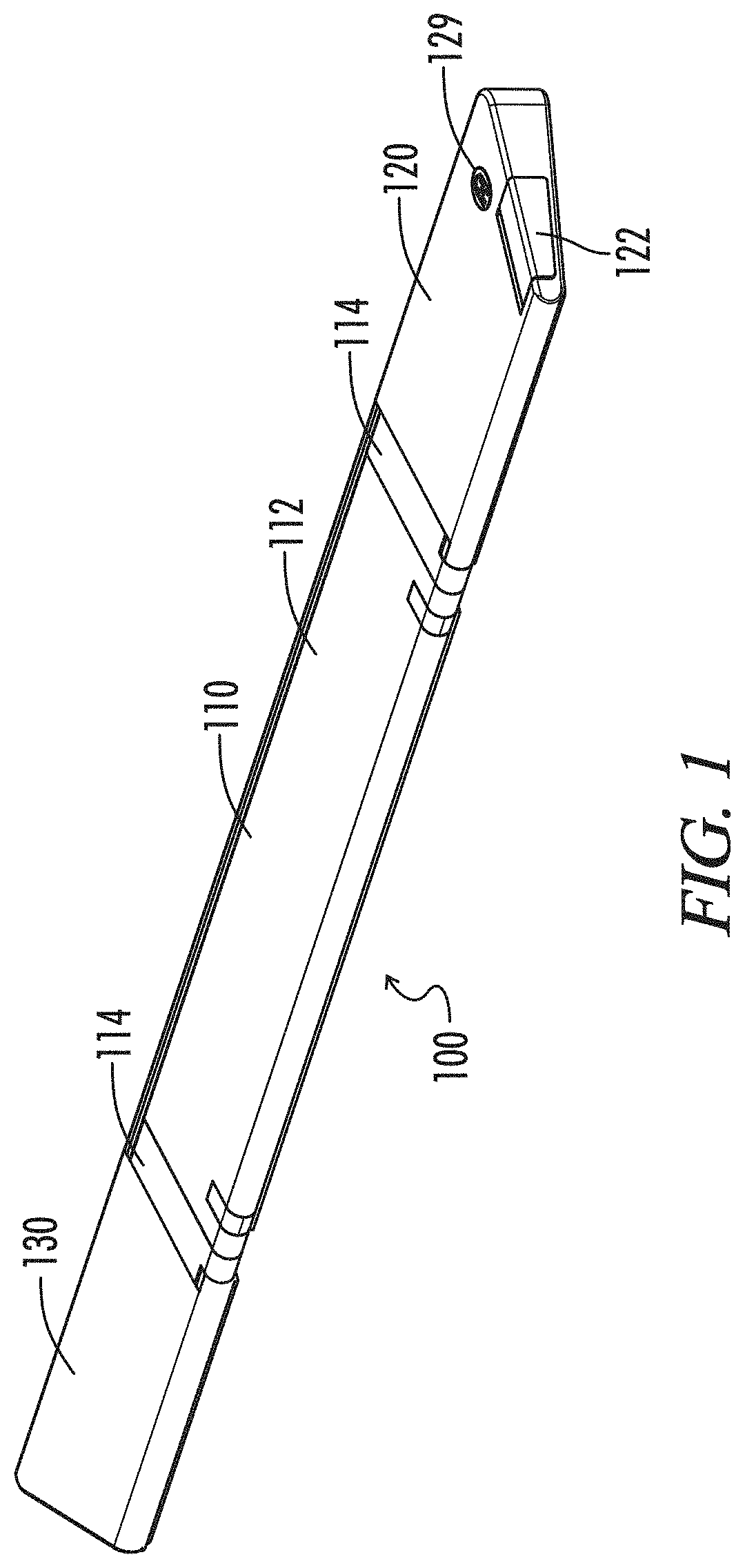
[0011] FIG. 1 is an elevated perspective view of a locking apparatus according to an exemplary embodiment.
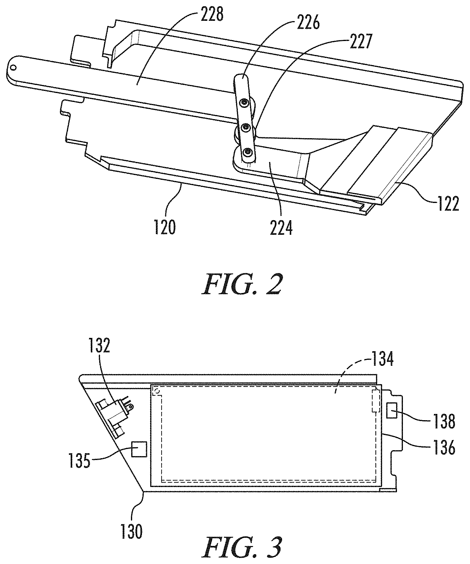
[0012] FIG. 2 is an elevated perspective view of an interior section of a power housing of a locking apparatus according to an exemplary embodiment.
[0013] FIG. 3 top internal view of an outer housing of a locking apparatus according to an exemplary embodiment.
[0014] FIG. 4 is an elevated perspective view of an interior portion of a central member of a locking apparatus according to an exemplary embodiment.
[0015] FIG. 5 is a bottom view of a locking apparatus according to an exemplary embodiment.
[0016] FIG. 6 is a side view of a locking apparatus and a riser according to an exemplary embodiment.
[0017] FIG. 7 is a side view of a locking apparatus and a connection plate according to an exemplary embodiment.
[0018] FIG. 8 is a side view of a locking apparatus in a locked state according to an exemplary embodiment.
[0019] FIG. 9 is a side view of a locking apparatus in an unlocked state according to an exemplary embodiment.
[0020] FIG. 10 is an overhead view of a sliding door Implementation of a locking apparatus in a locked state according to an exemplary embodiment.
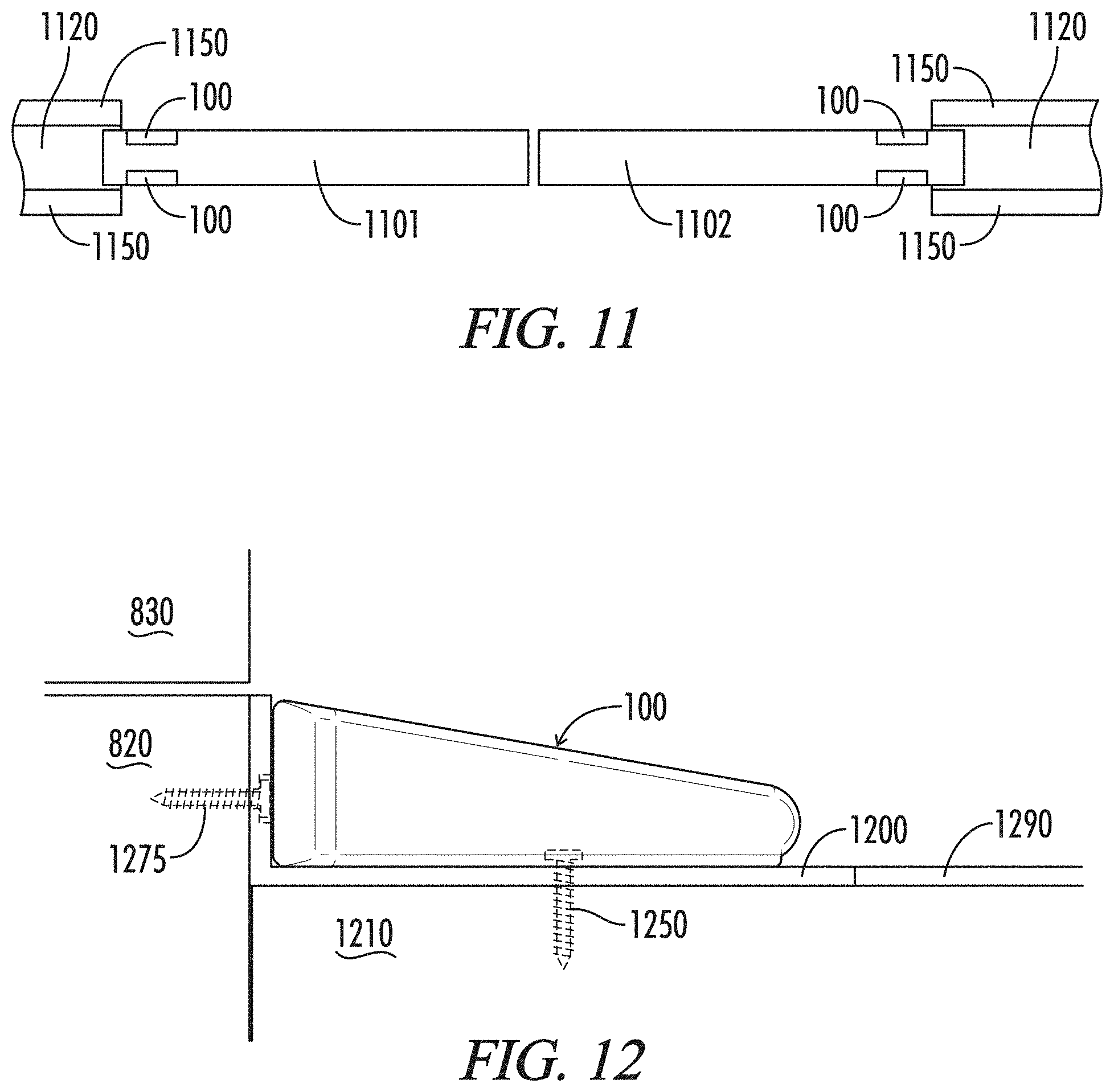
[0021] FIG. 11 is an overhead view of a sliding door Implementation of a plurality of locking apparatuses in unlocked states according to an exemplary embodiment.
[0022] FIG. 12 is a side view of a mounting bracket for a locking apparatus and a locking apparatus according to an exemplary embodiment.
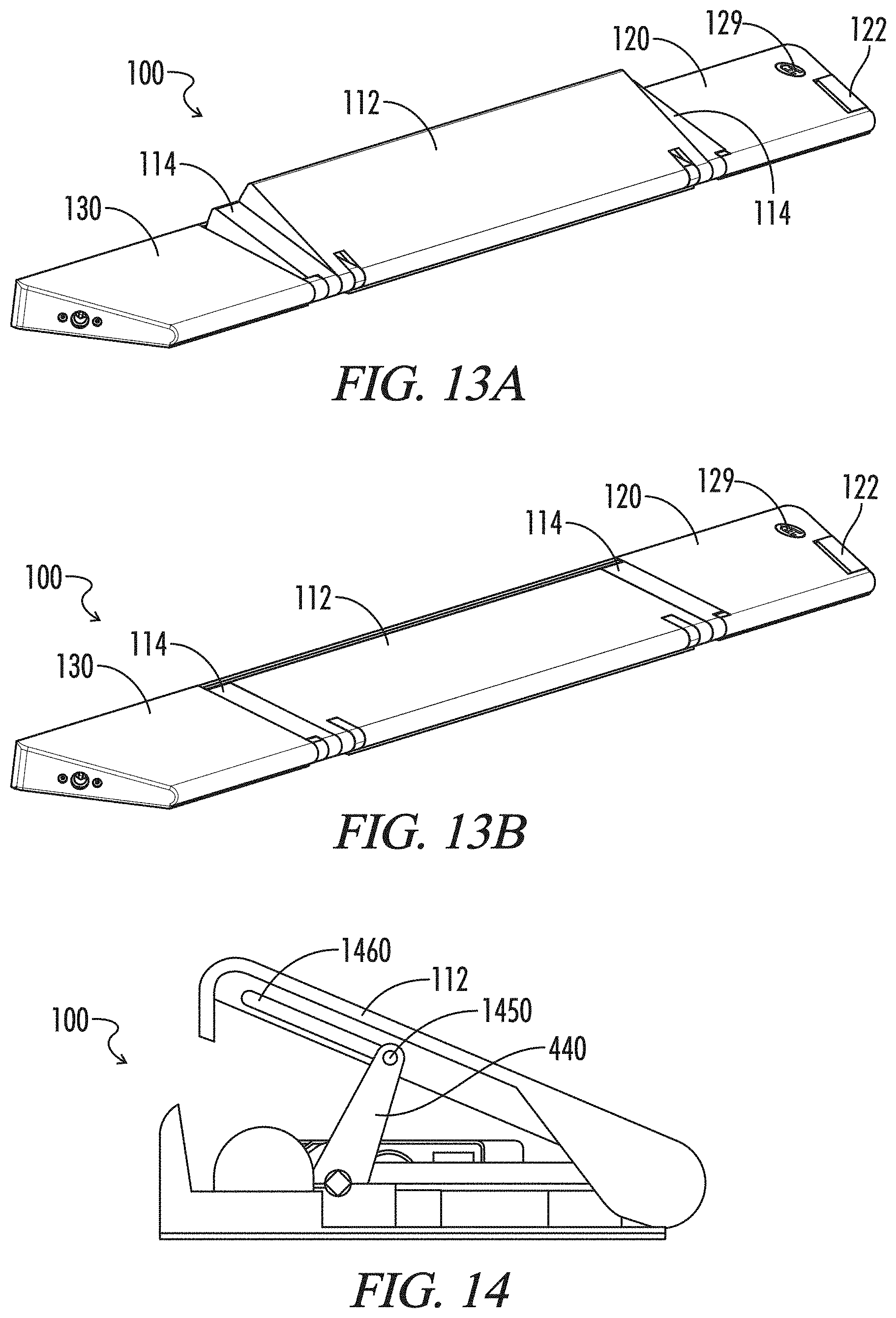
[0023] FIGS. 13A-B respectively illustrate a locking apparatus in a locked state and a locking apparatus in an unlocked state according to an exemplary embodiment.
[0024] FIG. 14 is a side view of a locking apparatus having a slot-type connection point according to an exemplary embodiment.
DETAILED DESCRIPTION
[0025] While the making and using of various exemplary embodiments of the present disclosure are discussed in detail below, it should be appreciated that the present disclosure provides many applicable inventive concepts that can be embodied in a wide variety of specific contexts. The specific embodiments discussed herein are merely illustrative of specific ways to make and use the invention and do not delimit the scope of the invention.
[0026] Where the various figures may describe embodiments sharing various common elements and features with other embodiments, similar elements and features are given the same reference numerals and redundant description thereof may be omitted below.
[0027] To facilitate the understanding of the embodiments described herein, a number of terms are defined below. The terms defined herein have meanings as commonly understood by a person of ordinary skill in the areas relevant to the present invention. Terms such as "a," "an," and "the" are not intended to refer to only a singular entity, but rather include the general class of which a specific example may be used for illustration. The terminology herein is used to describe specific embodiments of the invention, but their usage does not delimit the invention, except as set forth in the claims. The phrase "in one embodiment," as used herein does not necessarily refer to the same embodiment, although it may.
[0028] Conditional language used herein, such as, among others, "can," "might," "may," "e.g.," and the like, unless specifically stated otherwise, or otherwise understood within the context as used, is generally intended to convey that certain embodiments include, while other embodiments do not include, certain features, elements and/or states. Thus, such conditional language is not generally intended to imply that features, elements and/or states are in any way required for one or more embodiments or that one or more embodiments necessarily include logic for deciding, with or without author input or prompting, whether these features, elements and/or states are included or are to be performed in any particular embodiment.
[0029] The term "signal" as used herein may include any meanings as may be understood by those of ordinary skill in the art, including at least an electric or magnetic representation of current, voltage, charge, temperature, data or a state of one or more memory locations as expressed on one or more transmission mediums, and generally capable of being transmitted, received, stored, compared, combined or otherwise manipulated in any equivalent manner.
[0030] The term "user interface" as used herein may unless otherwise stated include any input-output module with respect to the hosted server including but not limited to web portals, such as individual web pages or those collectively defining a hosted website, mobile applications, desktop applications, telephony interfaces such as interactive voice response (IVR), and the like. Such interfaces may in a broader sense include pop-ups or links to third party websites for the purpose of further accessing and/or integrating associated materials, data or program functions via the hosted system and in accordance with methods of the present invention.
[0031] The terms "controller," "control circuit" and "control circuitry" as used herein may refer to, be embodied by or otherwise included within a machine, such as a general purpose processor, a digital signal processor (DSP), an application specific integrated circuit (ASIC), a field programmable gate array (FPGA) or other programmable logic device, discrete gate or transistor logic, discrete hardware components, or any combination thereof designed and programmed to perform or cause the performance of the functions described herein. A general purpose processor can be a microprocessor, but in the alternative, the processor can be a controller, microcontroller, or state machine, combinations of the same, or the like. A processor can also be implemented as a combination of computing devices, e.g., a combination of a DSP and a microprocessor, a plurality of microprocessors, one or more microprocessors in conjunction with a DSP core, or any other such configuration.
[0032] The term "communications medium" as used herein with respect to data communication between two or more parties or otherwise between communications network interfaces associated with two or more parties may refer to any one of, or a combination of any two or more of, telecommunications networks (whether wired, wireless, cellular or the like), a global network such as the Internet, local networks, network links, Internet Service Providers (ISP's), and intermediate communication interfaces.
[0033] To the extent that the term "includes" or "including" is used in the specification or the claims, it is intended to be inclusive in a manner similar to the term "comprising" as that term is interpreted when employed as a transitional word in a claim. Furthermore, to the extent that the term or is employed (e.g., A or B) it is intended to mean "A or B or both." When the applicants intend to indicate "only A or B but not both" then the term "only A or B but not both" will be employed. Thus, use of the term or herein is the inclusive, and not the exclusive use. See, Bryan A. Garner, A Dictionary of Modern Legal Usage 624 (2d. Ed. 1995). Also, to the extent that the terms "in" or "into" are used in the specification or the claims, it is intended to additionally mean "on" or "onto." Furthermore, to the extent the term "connect" is used in the specification or claims, it is intended to mean not only "directly connected to," but also "indirectly connected to" such as connected through another component or multiple components.
[0034] With reference to FIG. 1, provided is a locking apparatus 100 in accordance with an exemplary embodiment of the present disclosure. Locking apparatus 100 may comprise a central member 110 having a lifting member 112 and at least one stop member 114 located at an end thereof. In one embodiment, the locking apparatus 100 may comprise one or more of an outer housing 120 and power housing 130 connected thereto. The locking apparatus 100 may be modularly formed of a central member 110 and one or more of outer housing 120 and power housing 130. As used herein, the term "central" may denote aspects other than or in addition to a physical location. For example, the term "central" as used herein may convey an operational aspect and/or interrelationship as applied. In one exemplary embodiment, at least one of the outer housing 120 and power housing 130 may be physically located at a central location of an assembled locking apparatus 100 without departing from the spirit or scope of the present disclosure.
[0035] In one embodiment, the overall structure of the locking apparatus 100 may form a convex quadrilateral such as a trapezoid. In the exemplary embodiment illustrated at FIG. 1, for example, the central member 110 may be rectangularly shaped, while the outer housing 120 and power housing 130 may be shaped as a trapezoid. However, the shape of each of the central member 110, outer housing 120, and power housing 130 may vary based upon desired usage, thus an overall shape of the locking apparatus 100 may vary.
[0036] At least a portion of lifting member 112 of central member 110 may be configured to elevate during operation of the locking apparatus 100. In one exemplary embodiment described herein, at least a portion of the lifting member 112 may be elevated more at a proximal side of the locking apparatus 100 relative to a door frame than at a distal side relative to the door frame. In doing so, a force applied at the lifting member 112 by contact with a door or other object may be translated downwardly along the lifting member 112 and into a surface to which the locking apparatus is mounted, thereby increasing an amount of force capable of being resisted by the locking apparatus 100.
[0037] An inner portion of the lifting member 112 may comprise notches, divots, or cam receptacles. The notches, divots, or cam receptacles may be configured to be placed in contact with at least one cam 440 (as illustrated at FIG. 4 and described herein) of the central member 110. In one embodiment, the at least one cam 440 may be placed in constant contact with the lifting member 112 during operation. In an alternate embodiment, the at least one cam 440 may be configured to be placed in contact with the lifting member 112 only during particular operations, such as increasing a height of the lifting member 112 and/or decreasing the height of the lifting member 112.
[0038] The lifting member 112 may comprise a single structural element in one embodiment, or may comprise a plurality of structural elements without departing from the spirit and scope of the present disclosure. For example, in one embodiment the lifting member 112 may be formed of two or more structural elements which are configured to nest within each other when the locking apparatus 100 operates in an unlocked state, and to expand to separate associated heights when operating in a locked state. In one implementation, at least one of the plurality of structural elements may be selected based on a desired overall height of the lifting member 112 in a locked state. In a separate embodiment, the plurality of structural elements may collectively be arranged at a single height when in a locked position, and/or may provide for a single or a plurality of contact points with a door or object whose movement is intended to be restricted. When a plurality of nested structural elements are used for lifting member 112, a gap distance between a contact surface of the lifting member 112 and the door or object whose movement is intended to be restricted may be reduced as compared to a single lifting member embodiment. In addition to lifting member 112, a height of the at least one stop member 114 may be manipulated within the scope of the present disclosure. This may be accomplished, for example, based on a connection between the lifting member 112 and at least one stop member 114 and/or by connection between at least one cam 440 and the at least one stop member 114.
[0039] In one embodiment, locking apparatus 100 may comprise a single central member 110 without either or both of outer housing 120 and power housing 130 connected thereto. In another embodiment, one or more central members 110 may be connected to form a single locking apparatus 100. In this configuration, the plurality of central members 110 may communicate with one another to coordinate operation and function as a single member. In an alternate embodiment, a plurality of central members 110 may be interconnected as separate locking apparatuses 100, each operating independently of one another. Because of the modular nature of locking apparatus 100, a size associated with each component of the locking apparatus 100 may vary, and the ultimate size of a locking apparatus 100 depends on a size and number of each central member 110, outer housing 120, and/or power housing 130 connected thereto. Each of the central member 110, outer housing 120, and/or power housing 130 may be implemented in various sizes to permit usage in any intended application. For example, a central member 110 may be implemented having various widths and associated contact surface size, such that a central member 110 may have a width such as ten inches, thirty-six inches, or any other desired size based on implementation.
[0040] Outer housing 120 may be configured to physically and/or electrically connect to a central member 110. For example, an outer housing 120 may be connected to a central member 110 by moving the outer housing 120 inwardly towards the at least one stop member 114. In this example, the outer housing 120 or central member 110 may comprise a connection mechanism which detachably connects the outer housing 120 and central member 110 when the outer housing 120 is moved inwardly relative to the central member 110. Alternatively or in conjunction with attachment to the central member 110, the outer housing 120 and central member 110 may connect via at least a portion of the at least one stop member 114.
[0041] Each of the central member 110, outer housing 120, and/or power housing 130 may be formed of a durable material and each form a cavity therein. Examples of durable materials which may be used are glass-filled nylon such as nylon 66, metals such as aluminum, titanium, or the like, plastics, or any other material capable of structural rigidity sufficient for operating conditions of the locking apparatus 100. The central member 110, outer housing 120, and power housing 130 may each have a cavity formed therein configured to house internal components.
[0042] When combined, the locking apparatus may be configured to be arranged in an elongated structure with one or more central members 110, outer housings 120, and/or power housings 130 connected at one or more of opposing longitudinal ends of a central member 110. At least one other central member 110, outer housing 120, or power housing 130 may, in various embodiments, be attached to a central member 110 at any surface of the central member 110, based on a desired operational configuration (e.g., at a location other than a longitudinal end). Electrical connection(s) between internal components of central member 110 and between central member 110, outer housing 120, and power housing 130 may be accomplished by means of conventional wiring and connectors, which are not illustrated in the drawings for purposes of promoting clarity.
[0043] In one exemplary embodiment, the outer housing 120 may be configured with a locking mechanism 122 housed therein. Locking mechanism 122 may optionally be configured as a push/pull type manual unlock, a pressure sensitive foot pedal, or any other means of manual operation capable of engaging and/or disengaging an operational status of the locking apparatus 100. As illustrated, for example, in FIG. 2, a push-pull type mechanism may comprise an operating arm 224, crossmember 226, and engagement arm 228. Operating arm 224 and engagement arm 228 may be connected to each other by means of interconnection with the crossmember 226. Although crossmember 226 is illustrated in FIG. 2 as being connected to operating arm 224, engagement arm 228, and a central pivot point 227 by means of screws or bolts, any fastening means capable of attaching the crossmember 226 to the operating arm 224, engagement arm 228, and pivot point 227 may be used within the spirit and scope of the present disclosure.
[0044] In operation, the locking mechanism 122 may be configured to permit manual engagement or disengagement of the locking apparatus 100. For example, in one exemplary embodiment, the locking mechanism 122 may be configured such that at least a portion of operating arm 224 extends to protrude from an outer surface of the outer housing 120 when the locking apparatus 100 operates in a locked mode. If a user desires to manually disengage the locking apparatus 100, the user may push the operating arm 224 inwardly towards the central member 110. The movement of the operating arm 224 may cause the crossmember 226 to rotate relative to the pivot point 227, for example in either a clockwise or counter-clockwise direction. Based on its attachment to the engagement arm 228, crossmember 226's rotation may cause the engagement arm 228 to move in an engagement direction. In one embodiment, the engagement direction may be a longitudinal direction associated with the central member 110. Movement in the engagement direction may activate a manual release 420 of actuator 405 (illustrated at FIG. 4) to manipulate an operating status of the locking apparatus 100 in a manner as described herein.
[0045] Either alternatively or in addition to a push/pull type mechanism, other means of manual operation are contemplated within the scope of the present disclosure. For example, a foot pedal (not illustrated) may be used at an outer surface of the outer housing 120 to manipulate a manual release associated with the locking apparatus 100. For example, a foot pedal 54 and associated structure as described in Provisional Patent Application 62/038,393 (as incorporated by reference herein in its entirety) may be implemented for manual operation.
[0046] Outer housing 120 may further comprise an illuminating member 129. Illuminating member 129 may comprise a lighting element such as a light emitting diode (LED) or the like which is powered either by a power source (e.g., a battery or other input power) associated with the outer housing 120, or by an electrical connection to central member 110 or power housing 130. In one embodiment, a faceplate containing a logo or other item desired to be illuminated may be placed atop the illuminating member 129 to provide backlighting for the faceplate. In one exemplary embodiment, the illuminating member 129 may be configured to vary an illumination color based on a status of the locking apparatus 100. For example, the illuminating member 129 may display a first color while the locking apparatus operates in an unlocked mode, while a second color may be displayed while the locking apparatus operates in a locked mode. The illuminating member 129 may also be configured to vary a color or display mode for purposes of conveying information to a user. For example, the illuminating member may provide various color or display patterns to convey lock status, information related to usage (e.g., battery backup power usage, etc.), device pairing status, or any other information desired to be conveyed by the locking apparatus 100. Electrical connection(s) between internal components of outer housing 120 and between outer housing 120 and central member 110 may be accomplished by means of conventional wiring and connectors, which are not illustrated in the drawings for purposes of promoting clarity.
[0047] In one embodiment, one or more power housings 130 may be connected to a central member 110. As illustrated in FIG. 3, power housing 130 may comprise one or more of a power input 132 and battery 134. Power input 132 may be configured to be located at an outer surface of the power housing 130 and to receive input power from an external source (e.g., a power adapter or other power input means). In one embodiment, the power input 132 may be connected to the battery 134 and may be configured to provide charging power to the battery 134 when a power source is connected to the power input 132. Electrical connection(s) between internal components of power housing 130 and between power housing 130 and central member 110 may be accomplished by means of conventional wiring and connectors, which are not illustrated in the drawings for purposes of promoting clarity.
[0048] Battery 134 may comprise a lithium-ion, aluminum-ion, sodium-nickel chloride, polymer, or other battery design which is configured to provide sufficient power storage, durability, and/or thermal properties. Alternatively or in addition to the above-noted battery designs, battery 134 may comprise or include at least one ultracapacitor. In one exemplary embodiment, the battery 134 may comprise a rechargeable lithium-ion battery. The location of battery 134 and design within the power housing 130 may be configured so as to increase the longevity of holding a charge and to prevent damage to the battery 134 (e.g., by means of water damage, electrical charge, or wear and tear). The battery 134 may be positioned within the cavity of the power housing 130. In one embodiment, the battery 134 may be located within an insulated compartment 136. The insulated compartment 136 may be configured to be waterproof and to electrically insulate the battery 134 therein.
[0049] In one embodiment a battery backup 135 may be used either as part of battery 134 or as a standalone backup. The battery backup 135 may comprise, for example, one or more alkaline batteries electrically connected to the locking apparatus 100. The battery backup 135 may be used to provide power to the locking apparatus 100 in the event that the battery 134 has insufficient capacity or is incapable of meeting a power demand of the battery 134. For example, the battery backup 135 may provide power in the event that battery 134 is fully discharged, is not operating properly, or is low on power. In an exemplary embodiment, the one or more alkaline batteries may be selected so as to provide six months or more of operating the locking apparatus 100 according to ordinary usage. The battery backup 135 may comprise three AAA batteries in one embodiment.
[0050] In one exemplary embodiment, the locking apparatus 100 may provide a notice to a user that the locking apparatus 100 is operating on battery backup power. The locking apparatus 100 may communicate a status to a user in a number of ways. For example, the locking apparatus 100 may emit a noise such as a beep, either continuously or at a specified interval, the illuminating member may blink to indicate backup power, the locking apparatus 100 may transmit and electronic communication to convey backup power usage to a user, etc.
[0051] Power housing 130 may be configured to provide electrical power to the central member 110, for example by use of matching connectors 138 located at the power housing 130 and central housing 110. In one exemplary embodiment the matching connectors may be located within at least one of the cavities of the power housing 130 and central member 110. For example, power housing 130 may comprise a power housing connector 138 configured to electrically connect to a corresponding connector of central member 110. In one embodiment, the corresponding connector of central member 110 may be associated with a stop member 114; however the corresponding connector of central member 110 may additionally or alternatively be associated with the central member 110 of itself or internal component therein.
[0052] FIG. 4 illustrates internal components within the cavity of central member 110 according to an exemplary embodiment. A bottom surface of the central member 110 may comprise a base 401. At least one opening 402 may be formed in the base 401 at a distal side of the central member 110 relative to a door frame. The at least one opening 402 may have at least one rotation-enabling member 403 to permit at least a portion of lifting member 112 to elevate during operation. Central member 110 may further comprise an actuator 405. Actuator 405 may be variously implemented to provide for lifting power necessary to raise and/or lower lifting member 112 during operation. In one exemplary embodiment, the actuator 405 may comprise a servo; however any actuating device capable of manipulating a physical location of lifting member 112 may be used within the spirit and scope of the present disclosure. The actuator 405 may be mounted to the base 401 using mount 415 attached to or formed by the base 401. Actuator 405 may comprise a coupler 410 for connecting to an external translating member. In one embodiment, actuator 405 may be configured to provide an output corresponding to a locked and an unlocked state. For example, the actuator 405 may be configured in one embodiment to provide output rotation at a designated amount in a designated direction corresponding to each state.
[0053] Actuator 405 may further comprise a manual release 420. Manual release 420 may be configured to receive an input and to transition actuator 405 to a different operating state. For example, the manual release 420 may be configured to transition actuator 405 to an unlocked state from a locked state when an input is received from locking mechanism 122. Alternatively, the manual release 420 may be configured to permit purely manual operation by changing an operating state of the locking apparatus 100 when an input is received (i.e., by switching between a current locked state to an unlocked state or between a current unlocked state to a locked state upon receiving input).
[0054] In one embodiment, the coupler 410 of actuator 405 may attach to a shaft 425 at a shaft coupler 430. As illustrated, for example, at FIG. 4, the coupler 410 of actuator 405 and the shaft coupler 430 of shaft 425 may be implemented using matching notches to permit interconnection. However, connecting notches are not required to be used to connect the actuator 405 and shaft 425, and in one embodiment, the shaft 425 may connect directly to the actuator 405. The shaft 425 may be connected to the body 401 of central member 110 by means of at least one coupler 435. The at least one coupler 435 may be configured to hold the shaft 425 in position relative to the body 401, actuator 405, and/or lifting member 112,
[0055] At least one cam 440 may be connected to the shaft 425. The at least one cam 440 may be configured to rotate in a manner consistent with shaft 425 during operation, and may be placed in contact with an inner surface of the lifting member 112. Although two cams 440 are illustrated in FIG. 4, only one cam 440 may be used, or three or more cams 440 may be used without departing from the spirit and scope of the present disclosure. In one embodiment the at least one cam 440 may be positioned relative to the shaft 425 such as to reduce potential damage to components of the central member 110 when an external force is applied to lifting member 112 or any other portion of locking apparatus 100. Furthermore, the at least one cam 440 may be configured to maintain an angle relative to the lifting member 112 such that an external force applied to the lifting member 112 or other portion of locking apparatus 100 will not cause the at least one cam 440 to move or the shaft 425 to rotate. As such, in one embodiment, the configuration of the at least one cam 440 and shaft 425 may be such that structural rigidity and locking integrity is increased.
[0056] In one embodiment, the actuator 405 may cause the shaft 425 to rotate the at least one cam 440 such that an external surface of the lifting member 112 attains a predetermined angle relative to a surface upon which the locking apparatus 100 is mounted. The predetermined angle may be determined at a time of manufacture or may be configured by a user. The predetermined angle may be configured such that a contact position of the at least one cam 440 is perpendicular to the lifting member 112. The predetermined angle may vary based upon intended operation. For example, a smaller angle may be preferable where a small distance exists between a surface that the locking apparatus 100 is mounted upon and an object whose movement is to be retrieved, when compared to a greater distance. Alternatively, a larger angle may be preferable to resist an external force pushing downward upon an exterior surface of the lifting member 112. In one exemplary embodiment, a predetermined angle of between 15 and 20 degrees may be used. However, any angle may be used within the scope of the present disclosure for a corresponding intended purpose.
[0057] Central member 110 may further comprise a control circuit 450. In one embodiment, the control circuit 450 may be attached to the body 401 by means of circuit mount 460. In one embodiment, control circuit 450 is configured to control power distribution within the locking apparatus 100 and to enable automated control of the locking apparatus 100. In one exemplary embodiment, the control circuit 450 may comprise a transceiver 455 to send and receive control signals. In one embodiment, the transceiver 455 may comprise a wired or wireless connection medium. At least a portion of the transceiver 455 may be accessible from an outer surface of the locking apparatus 100 or may be wholly within the cavity of the central member 110. Transceiver 455 may permit communications across a communication medium using known communications protocols or proprietary communication protocols. For example, the transceiver 455 may permit the use of Ethernet, Bluetooth, Wi-Fi, a wireless application protocol, an IEEE 802 standard, or any other communications protocol, configuration, or implementation.
[0058] In one exemplary embodiment, the transceiver 455 may be configured to communicate with a software application running on a device. For example, the transceiver 455 may be configured to send and receive messages relating to a user device running the software application (e.g., by means of a user interface executed upon a device). The software application may be configured such that a user of the software may cause the control circuit 450 to actuate various operations corresponding to a user's command. For example, the software may enable a user to request that the locking apparatus 100 operate in either a locked or unlocked state. Upon receiving a requested operation at the transceiver 455, the control circuit 450 may control the locking apparatus 100 to perform the desired operation. The control circuit 450 may permit a great variety of desired automation and remote control capabilities. For example, in one exemplary embodiment, the control circuit 450 may be paired with a user device (e.g., using the Bluetooth protocol). After pairing, the control circuit 450 may be programmed to ensure that the locking apparatus 100 operates in an unlocked state whenever the paired user device is within a predetermined distance of the locking apparatus 100 (e.g., within ten feet).
[0059] Similarly, the control circuit 450 may, in one embodiment, permit the locking apparatus 100 to detect at least one device other than a paired user device and to notify an owner of the locking apparatus of an identifier associated with the detected device and/or provide the ability to remotely transition the locking apparatus 100 to a locked or unlocked state. The control circuit 450 may further enable the locking apparatus 100 to be programmed to operate in a locked or unlocked state at a predetermined time or event in one embodiment.
[0060] FIG. 5 illustrates a bottom view of an assembled locking apparatus according to an exemplary embodiment. As illustrated, central member 110 may comprise a bottom surface 510, outer housing 120 may comprise a bottom surface 520, and power housing 130 may comprise a bottom surface 530. Each of the bottom surfaces 510, 520, and 520 may be configured to include at least one mounting location 550. Each mounting location 550 may be used to secure the locking apparatus 100 to a surface upon which it is intended to be mounted.
[0061] Locking apparatus 100 may be attached to a surface upon which it is intended to be mounted using any one of at least one bolt, at least one hook and loop fastener, an adhesive material (e.g., any double sided tape, a tape such as 3M.TM. VHB.TM., etc.), or any other means of attachment, either alone or in combination. Furthermore, the means of attaching the locking apparatus 100 to the surface upon which it is intended to be mounted may be located upon at least one surface of the locking apparatus 100, the surface upon which it is intended to be mounted, or any combination thereof. In one exemplary embodiment, the locking apparatus 100 may comprise at least one opening at a bottom surface thereof which may be used to mount the locking apparatus 100 to an intended mounting location by placing a bolt, screw, nail, tape, or other affixing element into or through the at least one opening and into or onto the surface upon which the locking apparatus 100 is intended to be mounted. Optionally, the at least one opening may be provided by means of a mounting bracket configured to be placed between the locking apparatus 100 and mounting surface during installation.
[0062] At least one of the central member 110, outer housing 120, and power housing 130 may be placed In contact with a threshold and/or door frame to provide bracing and/or structural rigidity. The locking apparatus 100 may optionally be mounted to the threshold and/or door frame by means the same or similar mounting means as described herein.
[0063] In addition to use of a predetermined angle, other mechanisms for adjusting to a height between a surface upon which the locking apparatus 100 is mounted and a door height are contemplated within the scope of the present disclosure. For example, as illustrated at FIG. 6, a riser 600 may be used to increase an overall height of the locking apparatus 100. In one embodiment, the locking apparatus 100 may be mounted to the riser 600. The locking apparatus 100 may be mounted to the riser 600 at mounting point 610. Mounting point 610 may comprise any means of attaching the locking apparatus 100 to the riser 600 and/or surface 620. In one embodiment, the locking apparatus 100 may be attached to the riser 600 using screws or other fastening means.
[0064] The locking apparatus 100 may optionally be attached to the riser 600 using any single element or combination of at least one bolt, at least one hook and loop fastener, an adhesive material (e.g., any double sided tape, a tape such as 3M.TM. VHB.TM., etc.), or any other means of attachment. Furthermore, the means of attaching the locking apparatus 100 to the riser 600 may be located upon at least one surface of the locking apparatus 100, at least one surface of the riser 600, or any combination thereof.
[0065] In an alternative exemplary embodiment, a riser 600 may be placed atop an upper surface of lifting member 112 to increase an overall height thereof. In this configuration, the riser 600 may be attached directly to a top surface of riser 600 or may be attached to any portion of the locking apparatus 100 where such attachment is capable of preventing movement of the riser 600 relative to the locking apparatus 100.
[0066] In one exemplary embodiment, the riser 600 may be configured to conform to legal requirements for threshold height. For example, the riser 600 may be configured or adjusted to satisfy a one-half inch height requirement in accordance with the Americans with Disabilities Act (ADA). Because threshold height may vary widely based upon installation and indoor floor height, riser 600 may be used to help satisfy ADA height requirements, as well as to form an ideal contact surface between the locking apparatus 100 and an object whose movement is intended to be restricted. In one embodiment, the riser 600 may, for example, provide for at least one inch of lift and/or at least 30 degrees of elevation to the lifting member 112.
[0067] In one embodiment, the locking apparatus 100 may be configured to attach to a connection plate 700, as illustrated at FIG. 7. Connection plate 700 may be formed of any durable and/or rigid material capable of attachment to the locking apparatus 100. The connection plate 700 may be used in one embodiment to facilitate attachment of the locking apparatus 100 to the surface (e.g., surface 720) upon which the locking apparatus 100 is intended to be mounted. For example, the connection plate may provide pre-cut screw or bolt holes, may have double sided tape provided at predetermined locations, etc.
[0068] The connection plate 700 may be further configured to provide additional structural integrity and/or rigidity to the locking apparatus 100. In one embodiment, the connection plate may be designed for installation at a time when a door frame is installed. The connection plate 700 may be configured to be placed under door sill 710 and/or to attach to one or more surfaces of the door frame 710 in order to provide additional strength and rigidity. In one embodiment, the connection plate 700 may be connected to a sill frame and/or mounting bracket.
[0069] Connection plate 700 may be used either in place of or in addition to riser 600 as desired. For example, a thickness of the connection plate 700 may be adjustable or possess a thickness so as to incorporate desired features of riser 600.
[0070] In one embodiment, the connection plate 700 may comprise a universal installation plate (UIP) configured to permit installation of a locking apparatus according to a particular desired implementation. Although the use of a UIP is not required to be installed with a locking apparatus 100, use of a UIP may expand installation capability, for example to accommodate a particular floor surface, a distance of the locking apparatus 100 from a door frame, or a particular property makeup of a floor surface. The UIP may be configured to adjust to a plurality of door applications. A UIP may be mounted in a plurality of ways, for example, under a door threshold, between a door and a sill plate, or any other door, frame, or floor surface configuration. In one embodiment, the locking apparatus 100 may be configured to attach to a pressure treated main door sill plate associated with a foundation of a structure such as a building.
[0071] FIG. 8 illustrates a side view of an exemplary implantation of the present disclosure when the locking apparatus 100 is in a locked state. As illustrated in FIG. 8, a locking apparatus 100 may be mounted upon an intended mounting surface 810 (e.g., an interior floor). In the embodiment illustrated at FIG. 8, the locking apparatus 100 is mounted to the intended mounting surface 810 and/or threshold 820 using at least one fastener 815. At least one surface of the locking apparatus 100 may be optionally placed in contact with threshold 820. Door 830 may be configured to open inwardly toward the locking apparatus 100. When door 830 is opened, it may contact the lifting member 112 of locking apparatus 112 at a contact surface a. As previously described, a height of the contact surface a may be manipulated using riser 600, connection plate 700, or a combination thereof (see FIGS. 6-7), to achieve an optimal contact surface area between the locking apparatus 100 and door 830.
[0072] In operation, as the door 830 is placed in contact with the contact surface a, force associated with opening the door inwardly may be translated across the lifting member 112 of the locking apparatus 100 and through the bolts 815 and intended mounting surface 810 and/or threshold 820. By doing so, door opening may be resisted or prevented, and entry may be denied. Furthermore, by providing a floor-mounted locking mechanism, existing entry prevention mechanisms may be enhanced. Because forces received at the contact surface a of locking apparatus 100 are translated into the intended mounting surface 810 and/or threshold 820, forces far exceeding that needed to defeat existing door lock mechanisms may be received by the locking apparatus 100 without permitting entry.
[0073] FIG. 9 illustrates a side view of an exemplary implantation of the present disclosure where the locking apparatus 100 is in an unlocked state. As shown in FIG. 9, when the locking apparatus 100 is in an unlocked state, door 830 is free to open inwardly without being placed in contact with contact surface a, since contact surface a is nested within the locking apparatus 100 when operating in the unlocked mode.
[0074] Although the present disclosure generally illustrates a floor-mounted locking mechanism, one or more locking apparatuses 100 in accordance with the present disclosure may be implemented at any surface upon which movement of an object to be restrained may be restricted. For example, at least one locking apparatus 100 may be positioned at a vertical portion of a door or window frame or sill and may operate in the same manner as previously described to restrict movement of an object whose movement is intended to be restricted.
[0075] For example, FIG. 10 illustrates a locking apparatus 100 configured to restrict movement of a sliding door 1000 which moves horizontally relative to a door frame 1050. In this embodiment, the locking apparatus 100 may be positioned such that when lifting member 112 is in a locked state, the sliding door 1000 is blocked from opening by either the sliding door 1000 or frame 1050 being placed in contact with the contact surface a of the locking apparatus 100. As noted in FIG. 10, the locking apparatus 100 may be positioned at either of the sliding door 1000 or frame 1050 in this embodiment to provide a similar or same result.
[0076] FIG. 11 illustrates an exemplary embodiment in which sliding doors 1101 and 1102 are configured to open and close by moving along one or more tracks 1120 enclosed by rails 1150. In this exemplary embodiment, one or more locking apparatuses 100 may be implemented at each of sliding doors 1101 and 1102 to restrict movement of the doors along track 1120. For example, sliding doors 1101 and 1102 may be prevented from opening when lifting members 112 of locking apparatuses 100 are in a locked position, as contact between the contact surfaces a of the locking apparatuses 100 and the rails 1150 prevent the sliding doors 1101 and 1102 from moving outwardly along rails 1120.
[0077] FIG. 12 illustrates a mounting bracket 1200 according to an exemplary embodiment. In one embodiment, the locking apparatus 100 may be attached to a mounting bracket 1200. Alternatively, the locking apparatus may be attached to mounting bracket 1200 at time of installation and mounting to at least one of threshold 820 and surface 1210, for example, by placing a screw, bolt, portion of double sided tape, etc. through at least one opening into which screws 1250 and/or 1275 are placed, as illustrated in FIG. 12. In one embodiment, a carpet or other top surface 1290 may be removed to properly mount the mounting bracket 1200 and locking apparatus 100 to the surface 1210. Although screw 1275 is not illustrated as penetrating through a portion of the locking apparatus 100, it should be understood that both the mounting bracket 1200 and locking apparatus 100 may be secured to the threshold 820 by means of screw 1275, for example by pre-forming a passage through an outer surface of the locking apparatus 100, or by drilling through or otherwise penetrating an outer surface of the locking apparatus 100 either before installing the screw 1275 or at the time of installing screw 1275.
[0078] In one embodiment, mounting bracket 1200 may be formed of metal, plastic, glass-filled nylon, or any other material capable of rigidity and durability during operation of the locking apparatus 100. In one embodiment, the connection plate 700 may be formed, at least in part, by a mounting bracket 1200. For example, the connection plate 700 may comprise mounting bracket 1200 attached to or otherwise connected with an extending portion which extends under a door frame or sill.
[0079] FIGS. 13A-B illustrate a locking apparatus 100 in a locked state (FIG. 13A) and in an unlocked state (FIG. 13B) in accordance with an exemplary embodiment of the present disclosure. In one embodiment, at least a portion of the at least one stop member 114 may be configured to elevate at a same or similar rate to that of lifting portion 112, and may be configured to reach a positional height in a locked state of the lifting portion 112 or at least a portion thereof. Each at least one stop member 114 may be configured to elevate using at least one cam in a similar manner to that of lifting portion 112, or may be connected to lifting portion 112 in a manner which permits a height of the at least one stop member 114 to be manipulated. Although illustrated as comprising a single surface whose height is manipulated, in one exemplary embodiment, the lifting portion may comprise a plurality of lifting sections each having respective contact surfaces with a device whose movement is intended to be restricted.
[0080] FIG. 14 illustrates a side view of a locking apparatus 100 according an exemplary embodiment of the present disclosure. In the embodiment illustrated by FIG. 14, at least one cam 440 may be configured with a connector 1450 at a surface thereof. The connector 1450 may be configured to be received by and connected to a slot 1460 located at an interior surface of the lifting portion 112. In one embodiment, connection between the connector 1450 and slot 1460 may permit the at least one cam 440 to control both lifting and lowering of a height associated with the lifting portion 112. By placing the connector 1450 into the slot 1460, movement of the cam 440 may cause a position of the connector 1450 within the slot 1460 to move such that at least one of a lifting motion and a lowering motion is achieved based on movement of the cam 440.
[0081] The previous detailed description has been provided for the purposes of illustration and description. Thus, although there have been described particular embodiments of the present invention of a new and useful "Improved Locking Apparatus, Locking Member, and Method of Use," it is not intended that such references be construed as limitations upon the scope of this invention.
* * * * *
D00000
D00001
D00002
D00003
D00004
D00005
D00006
D00007
XML
uspto.report is an independent third-party trademark research tool that is not affiliated, endorsed, or sponsored by the United States Patent and Trademark Office (USPTO) or any other governmental organization. The information provided by uspto.report is based on publicly available data at the time of writing and is intended for informational purposes only.
While we strive to provide accurate and up-to-date information, we do not guarantee the accuracy, completeness, reliability, or suitability of the information displayed on this site. The use of this site is at your own risk. Any reliance you place on such information is therefore strictly at your own risk.
All official trademark data, including owner information, should be verified by visiting the official USPTO website at www.uspto.gov. This site is not intended to replace professional legal advice and should not be used as a substitute for consulting with a legal professional who is knowledgeable about trademark law.