Membrane-Coupled Cathode for the Reduction of Carbon Dioxide in Acid-Based Electrolytes Without Mobile Cations
Schmid; Bernhard ; et al.
U.S. patent application number 16/629728 was filed with the patent office on 2021-03-18 for membrane-coupled cathode for the reduction of carbon dioxide in acid-based electrolytes without mobile cations. This patent application is currently assigned to Siemens Aktiengesellschaft. The applicant listed for this patent is Siemens Aktiengesellschaft. Invention is credited to Christian Reller, Bernhard Schmid, Gunter Schmid.
| Application Number | 20210079538 16/629728 |
| Document ID | / |
| Family ID | 1000005289159 |
| Filed Date | 2021-03-18 |


View All Diagrams
| United States Patent Application | 20210079538 |
| Kind Code | A1 |
| Schmid; Bernhard ; et al. | March 18, 2021 |
Membrane-Coupled Cathode for the Reduction of Carbon Dioxide in Acid-Based Electrolytes Without Mobile Cations
Abstract
Various embodiments include an electrolysis cell comprising: a cathode space housing a cathode for the reduction of CO.sub.2; a first ion exchange membrane including an anion exchanger and/or an anion transporter, the first ion exchange membrane adjoining the cathode space and in direct contact with the cathode; an anode space housing an anode; a first separator membrane; and a salt bridge space housing an electrolyte disposed between the first ion exchange membrane and the first separator membrane. The electrolyte in the salt bridge space comprises a liquid acid and/or a solution of an acid.
| Inventors: | Schmid; Bernhard; (Duren, DE) ; Reller; Christian; (Minden, DE) ; Schmid; Gunter; (Hemhofen, DE) | ||||||||||
| Applicant: |
|
||||||||||
|---|---|---|---|---|---|---|---|---|---|---|---|
| Assignee: | Siemens Aktiengesellschaft Munchen DE |
||||||||||
| Family ID: | 1000005289159 | ||||||||||
| Appl. No.: | 16/629728 | ||||||||||
| Filed: | June 14, 2018 | ||||||||||
| PCT Filed: | June 14, 2018 | ||||||||||
| PCT NO: | PCT/EP2018/065854 | ||||||||||
| 371 Date: | January 9, 2020 |
| Current U.S. Class: | 1/1 |
| Current CPC Class: | C25B 9/63 20210101; C25B 9/23 20210101; C25B 1/00 20130101 |
| International Class: | C25B 9/10 20060101 C25B009/10; C25B 9/02 20060101 C25B009/02; C25B 1/00 20060101 C25B001/00 |
Foreign Application Data
| Date | Code | Application Number |
|---|---|---|
| Jul 12, 2017 | DE | 10 2017 211 930.6 |
Claims
1. An electrolysis cell comprising: a cathode space housing a cathode for the reduction of CO.sub.2; a first ion exchange membrane including an anion exchanger and/or an anion transporter, the first ion exchange membrane adjoining the cathode space and in direct contact with the cathode; an anode space housing an anode; a first separator membrane; and a salt bridge space housing an electrolyte disposed between the first ion exchange membrane and the first separator membrane; wherein the electrolyte in the salt bridge space comprises a liquid acid and/or a solution of an acid.
2. An electrolysis cell comprising: a cathode space housing a cathode for reducing CO.sub.2; a first ion exchange membrane including an anion exchanger and/or anion transporter, the first ion exchange membrane adjoining the cathode space and in direct contact with the cathode; and an anode space housing an anode and containing an electrolyte, the anode space adjoining the first ion exchange membrane; wherein the electrolyte in the anode space comprises a liquid acid and/or a solution of an acid.
3. The electrolysis cell as claimed in claim 1, wherein the second ion exchange membrane is selected from the group consisting of: an ion exchange membrane containing a cation exchanger, a bipolar membrane, and a diaphragm.
4. The electrolysis cell as claimed in claim 1, wherein the anode space houses an anolyte comprising a liquid and/or dissolved acid.
5. The electrolysis cell as claimed in claim 2, wherein the anode is in direct contact with the first ion exchange membrane.
6. The electrolysis cell as claimed in claim 1, wherein the electrolysis is conducted with a current density of more than 50 mAcm.sup.-2.
7. The electrolysis cell as claimed in claim 1, wherein: an acid of the electrolyte in the salt bridge space has a pK.sub.A of 6 or less; and the liquid and/or dissolved acid comprises at least one acid selected from the group consisting of: dilute or neat H.sub.2SO.sub.4, a solution of H.sub.2N--SO.sub.2--OH, dilute or neat HClO.sub.4, a solution of H.sub.3PO.sub.4, dilute or neat CF.sub.3--COOH, dilute or neat CF.sub.3--SO.sub.2--OH, a solution of (CF.sub.3--SO.sub.2).sub.2--NH, a solution of HF, dilute or neat HCOOH, dilute or neat CH.sub.3--COOH, a solution of HCl, a solution of HBr, and a solution of HI.
8. An electrolysis cell comprising: a cathode space housing a cathode; a first ion exchange membrane including an anion exchanger and/or anion transporter, the first ion exchange membrane adjoining the cathode space in direct contact with the cathode; an anode space housing an anode; a diaphragm adjoining the anode space; and a salt bridge space disposed between the first ion exchange membrane and the diaphragm; wherein the diaphragm is non-ion conductive.
9. The electrolysis cell as claimed in claim 8, wherein at least one of: the anode is in contact with the diaphragm; the anode is in contact with a conductive structure on the side remote from the salt bridge space; or the cathode is in contact with a conductive structure on the side remote from the salt bridge space.
10. The electrolysis cell as claimed in claim 8, wherein at least one of the cathode or the anode comprises at least one structure selected from the group consisting of: a gas diffusion electrode, a porous bound catalyst structure, a particulate catalyst on a support, a coating of a particulate catalyst on the first and/or second ion exchange membrane, a porous conductive carrier impregnated with a catalyst, and a noncontinuous sheetlike structure.
11. The electrolysis cell as claimed in claim 10, wherein: the cathode comprises at least one structure selected from the group consisting of: a gas diffusion electrode, a porous bound catalyst structure, a particulate catalyst on a support, a coating of a particulate catalyst on the first and/or second ion exchange membrane, a porous conductive carrier impregnated with a catalyst, and of a noncontinuous sheetlike structure containing an anion exchange material and/or anion transport material; and the anode comprises at least one structure selected from the group consisting of: a gas diffusion electrode, a porous bound catalyst structure, a particulate catalyst on a support, a coating of a particulate catalyst on the first and/or second ion exchange membrane, a porous conductive carrier impregnated with a catalyst, and a noncontinuous sheetlike structure containing a cation exchange material.
12. The electrolysis cell as claimed in claim 8, wherein at least one of the first ion exchange membrane or the diaphragm is hydrophilic.
13. The electrolysis cell as claimed in claim 8, wherein the electrolyte in the salt bridge space comprises a liquid acid and/or a solution of an acid.
14. An electrolysis system comprising an electrolysis cell comprising: a cathode space housing a cathode; a first ion exchange membrane including an anion exchanger and/or anion transporter, the first ion exchange membrane adjoining the cathode space in direct contact with the cathode; an anode space housing an anode; a diaphragm adjoining the anode space; and a salt bridge space disposed between the first ion exchange membrane and the diaphragm; wherein the diaphragm is non-ion conductive.
15. The electrolysis system as claimed in claim 14, further comprising a recycling device connected to an outlet from the salt bridge space and an inlet to the cathode space, to return a reactant from the cathode reaction that can be formed in the salt bridge space to the cathode space.
16. (canceled)
Description
CROSS-REFERENCE TO RELATED APPLICATIONS
[0001] This application is a U.S. National Stage Application of International Application No. PCT/EP2018/065854 filed Jun. 14, 2018, which designates the United States of America, and claims priority to DE Application No. 10 2017 211 930.6 filed Jul. 12, 2017, the contents of which are hereby incorporated by reference in their entirety.
TECHNICAL FIELD
[0002] The present disclosure relates to electrolysis of CO.sub.2. Various embodiments include methods of electrolysis, electrolysis systems comprising an electrolysis cell.
BACKGROUND
[0003] The combustion of fossil fuels currently covers about 80% of global energy demand. These combustion processes emitted about 34,032.7 million metric tons of carbon dioxide (CO.sub.2) globally into the atmosphere in 2011. This release is the simplest way of disposing of large volumes of CO.sub.2 as well (brown coal power plants exceeding 50,000 t per day). Discussion about the adverse effects of the greenhouse gas CO.sub.2 on the climate has led to consideration of reutilization of CO.sub.2. In thermodynamic terms, CO.sub.2 is at a very low level and can therefore be reduced again to usable products only with difficulty.
[0004] Systematic studies of the electrochemical reduction of carbon dioxide are still a relatively new field of development. Only in the last few years have there been efforts to develop an electrochemical system that can reduce an acceptable amount of carbon dioxide. Research on the laboratory scale has shown that electrolysis of carbon dioxide should preferably be accomplished using metals as catalysts. The publication "Electrochemical CO.sub.2 reduction on metal electrodes" by Y. Hori, published in: C. Vayenas, et al. (eds.), Modern Aspects of Electrochemistry, Springer, New York, 2008, p. 89-189, discloses, by way of example, Faraday efficiencies (FE) at different metal cathodes, some of which are shown by way of example in table 1.
TABLE-US-00001 TABLE 1 Faraday efficiencies for the conversion of CO.sub.2 to various products at various metal electrodes Electrode CH.sub.4 C.sub.2H.sub.4 C.sub.2H.sub.5OH C.sub.3H.sub.7OH CO HCOO.sup.- H.sub.2 Total Cu 33.3 25.5 5.7 3.0 1.3 9.4 20.5 103.5 Au 0.0 0.0 0.0 0.0 87.1 0.7 10.2 98.0 Ag 0.0 0.0 0.0 0.0 81.5 0.8 12.4 94.6 Zn 0.0 0.0 0.0 0.0 79.4 6.1 9.9 95.4 Pd 2.9 0.0 0.0 0.0 28.3 2.8 26.2 60.2 Ga 0.0 0.0 0.0 0.0 23.2 0.0 79.0 102.0 Pb 0.0 0.0 0.0 0.0 0.0 97.4 5.0 102.4 Hg 0.0 0.0 0.0 0.0 0.0 99.5 0.0 99.5 In 0.0 0.0 0.0 0.0 2.1 94.9 3.3 100.3 Sn 0.0 0.0 0.0 0.0 7.1 88.4 4.6 100.1 Cd 1.3 0.0 0.0 0.0 13.9 78.4 9.4 103.0 Tl 0.0 0.0 0.0 0.0 0.0 95.1 6.2 101.3 Ni 1.8 0.1 0.0 0.0 0.0 1.4 88.9 92.4 Fe 0.0 0.0 0.0 0.0 0.0 0.0 94.8 94.8 Pt 0.0 0.0 0.0 0.0 0.0 0.1 95.7 95.8 Ti 0.0 0.0 0.0 0.0 0.0 0.0 99.7 99.7
[0005] Table 1 states Faraday efficiencies (FE) (in [%]) of products formed in carbon dioxide reduction at various metal electrodes. The values reported are applicable to a 0.1 M potassium hydrogencarbonate solution as electrolyte. As apparent from table 1, the electrochemical reduction of CO.sub.2 at solid-state electrodes in aqueous electrolyte solutions offers a multitude of possible products.
[0006] There are currently discussions about the electrification of the chemical industry. This means that chemical commodities or fuels are to be produced preferentially from CO.sub.2 and/or CO and/or H.sub.2O with supply of surplus electrical energy, preferably from renewable sources. In the phase of introduction of such technology, the aim is for the economic value of a substance to be significantly greater than its calorific value, in order to achieve economic viability at an early stage.
[0007] To achieve acceptable conversion rates in CO.sub.2 electrolysis, it is preferable to ensure sufficient availability of CO.sub.2 at the catalytically active sites of the cathode. At current densities exceeding .about.50 mAcm.sup.-2, however, this supply is difficult through the solubility of CO.sub.2 in an electrolyte. Therefore, at high current densities, the CO.sub.2 is typically supplied directly as gas. What is called a three-phase zone is advantageous here, where the reaction gas CO.sub.2, the catalytically active electrode and the electrolyte are available. For this purpose, it is possible to use porous electrodes, called gas diffusion electrodes, which can be implemented in various ways.
[0008] For example, they may take the form of electrically conductive catalyst particles bound to polymers, for example of an extruded or calendered film, which corresponds to an all-active-catalyst gas diffusion electrode, or of a porous, catalytically inactive but conductive electrode, for example in the form of carbon fiber gas diffusion layers impregnated with a small amount of active catalyst particles.
[0009] As an alternative, it is also possible to bind a catalyst to a solid-state electrolyte, which can also be referred to as a catalyst-coated membrane. In this case too, it is possible for a three-phase zone to form between the catalyst, the solid-state electrolyte and the CO.sub.2. With appropriate structures, an electrochemical reduction of CO.sub.2 to chemically utilizable products is possible. For example, US 2017/0037522 A1 describes a process for preparing formic acid in an electrochemical apparatus.
[0010] In addition, acids in the anode space are also completely standard practice, as described, for example, in J. Shi, F. Shi, N. Song, J-X. Liu, X-K Yang, Y-J Jia, Z-W Xiao, P. Du, Journal of Power Sources, 2014, 259, 50-53. However, there is a need for a simple and effective electrolytic method of reducing CO.sub.2 using high current densities with simultaneous avoidance of the formation of CO.sub.2 at the anode, for example by protolysis of carbonate-containing electrolytes in aqueous electrolytes. Electrolysis cells in which the CO.sub.2/O.sub.2 mixtures form at the anode are known, for example, from US 2016 0251755 A1 and U.S. Pat. No. 9,481,939.
SUMMARY
[0011] As an example, some embodiments of the teachings herein include a method of electrolysis of CO.sub.2, wherein an electrolysis cell comprising a cathode space comprising a cathode; a first ion exchange membrane which contains an anion exchanger and/or anion transporter and adjoins the cathode space, where the cathode forms direct contact with the first ion exchange membrane; an anode space comprising an anode; a first separator membrane; and a salt bridge space, where the salt bridge space is disposed between the first ion exchange membrane and the first separator membrane, is used; wherein CO.sub.2 is reduced at the cathode, wherein the electrolyte in the salt bridge space consists of a liquid acid and/or a solution of an acid.
[0012] In some embodiments, an electrolysis cell comprising a cathode space comprising a cathode; a first ion exchange membrane which contains an anion exchanger and/or anion transporter and adjoins the cathode space, where the cathode forms direct contact with the first ion exchange membrane; and an anode space comprising an anode, where the anode space adjoins the first ion exchange membrane is used; wherein CO.sub.2 is reduced at the cathode, wherein the electrolyte in the anode space consists of a liquid acid and/or a solution of an acid.
[0013] In some embodiments, the second ion exchange membrane is selected from an ion exchange membrane containing a cation exchanger, a bipolar membrane and a diaphragm.
[0014] In some embodiments, the anode space comprises an anolyte comprising a liquid and/or dissolved acid, preferably wherein the anolyte and/or the acid in the salt bridge space does not comprise any mobile cations except for protons and/or deuterons, especially any metal cations.
[0015] In some embodiments, the anode lies against the first ion exchange membrane.
[0016] In some embodiments, the electrolysis is conducted with a current density of more than 50 mAcm.sup.-2, more than 100 mAcm.sup.-2, of 150 mAcm.sup.-2 or more, 170 mAcm.sup.-2 or more, 250 mAcm.sup.-2 or more, 400 mAcm.sup.-2 or more, or 600 mAcm.sup.-2 or more.
[0017] In some embodiments, an acid of the electrolyte in the salt bridge space has a pK.sub.A of 6 or less, 5 or less, 3 or less, 1 or less, or 0 or less, wherein the liquid and/or dissolved acid is selected from dilute or neat H.sub.2SO.sub.4, a solution of H.sub.2N--SO.sub.2--OH, dilute or neat HClO.sub.4, a solution of H.sub.3PO.sub.4, dilute or neat CF.sub.3--COOH, dilute or neat CF.sub.3--SO.sub.2--OH, a solution of (CF.sub.3--SO.sub.2).sub.2--NH, a solution of HF, dilute or neat HCOOH, dilute or neat CH.sub.3--COOH, a solution of HCl, a solution of HBr, a solution of HI, and/or mixtures thereof.
[0018] As another example, some embodiments include an electrolysis cell comprising: a cathode space comprising a cathode; a first ion exchange membrane which contains an anion exchanger and/or anion transporter and adjoins the cathode space, where the cathode forms direct contact with the first ion exchange membrane; an anode space comprising an anode; and a diaphragm that adjoins the anode space; further comprising a salt bridge space, wherein the salt bridge space is disposed between the first ion exchange membrane and the diaphragm, wherein the diaphragm is non-ion-conductive.
[0019] In some embodiments, the anode is in contact with the diaphragm, and/or wherein the anode and/or the cathode is in contact with a conductive structure on the side remote from the salt bridge space.
[0020] In some embodiments, the cathode and/or the anode takes the form of a gas diffusion electrode, of a porous bound catalyst structure, of a particulate catalyst on a support, of a coating of a particulate catalyst on the first and/or second ion exchange membrane, of a porous conductive carrier impregnated with a catalyst, and/or of a noncontinuous sheetlike structure.
[0021] In some embodiments, the cathode takes the form of a gas diffusion electrode, of a porous bound catalyst structure, of a particulate catalyst on a support, of a coating of a particulate catalyst on the first and/or second ion exchange membrane, of a porous conductive carrier impregnated with a catalyst, and/or of a noncontinuous sheetlike structure, containing an anion exchange material and/or anion transport material, and/or wherein the anode takes the form of a gas diffusion electrode, of a porous bound catalyst structure, of a particulate catalyst on a support, of a coating of a particulate catalyst on the first and/or second ion exchange membrane, of a porous conductive carrier impregnated with a catalyst, and/or of a noncontinuous sheetlike structure, containing a cation exchange material.
[0022] In some embodiments, the first ion exchange membrane and/or the diaphragm are hydrophilic.
[0023] In some embodiments, the electrolyte in the salt bridge space consists of a liquid acid and/or a solution of an acid, preferably wherein an acid in the electrolyte in the salt bridge space has a pK.sub.A of 6 or less, preferably 5 or less, further preferably 3 or less, even further preferably 1 or less, especially preferably 0 or less, further preferably wherein the liquid and/or dissolved acid is selected from dilute or neat H.sub.2SO.sub.4, a solution of H.sub.2N--SO.sub.2--OH, dilute or neat HClO.sub.4, a solution of H.sub.3PO.sub.4, dilute or neat CF.sub.3--COOH, dilute or neat CF.sub.3--SO.sub.2--OH, a solution of (CF.sub.3--SO.sub.2).sub.2--NH, a solution of HF, dilute or neat HCOOH, dilute or neat CH.sub.3--COOH, a solution of HCl, a solution of HBr, a solution of HI, and/or mixtures thereof.
[0024] As another example, some embodiments include an electrolysis system comprising an electrolysis cell as described above.
[0025] In some embodiments, there is a recycling device connected to an outlet from the salt bridge space and an inlet to the cathode space, which is set up to return a reactant from the cathode reaction that can be formed in the salt bridge space to the cathode space.
BRIEF DESCRIPTION OF THE DRAWINGS
[0026] The appended drawings are intended to illustrate embodiments of the teachings of the present disclosure and impart further understanding thereof. In association with the description, they serve to explain concepts and principles herein. Other embodiments and many of the advantages mentioned are also apparent with regard to the drawings. The elements of the drawings are not necessarily shown true to scale with respect to one another. Elements, features and components that are the same, have the same function and the same effect, unless stated otherwise, are each given the same reference numerals.
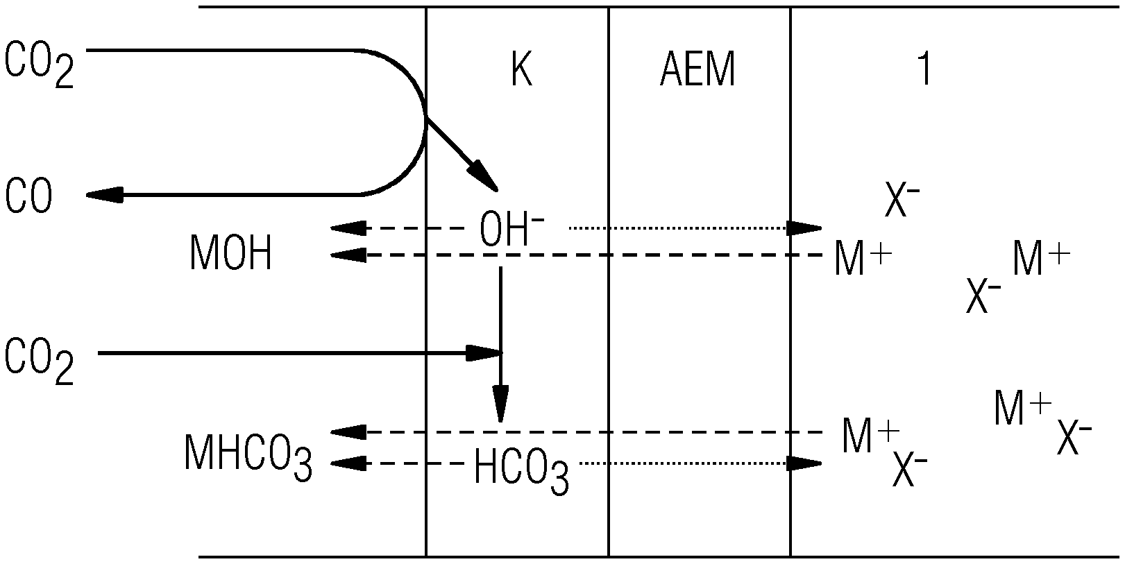
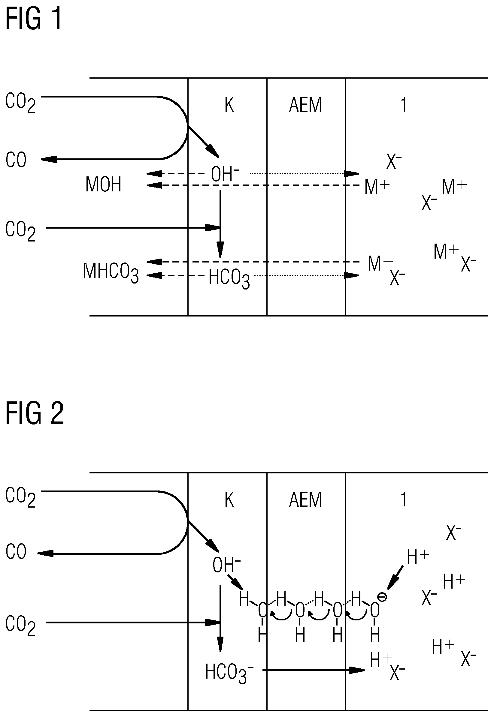
[0027] FIGS. 1 and 2 show a graphic representation of the cathodic half-cell of the above-described transport model of ions of salts and acids in an AEM adjoining a cathode.
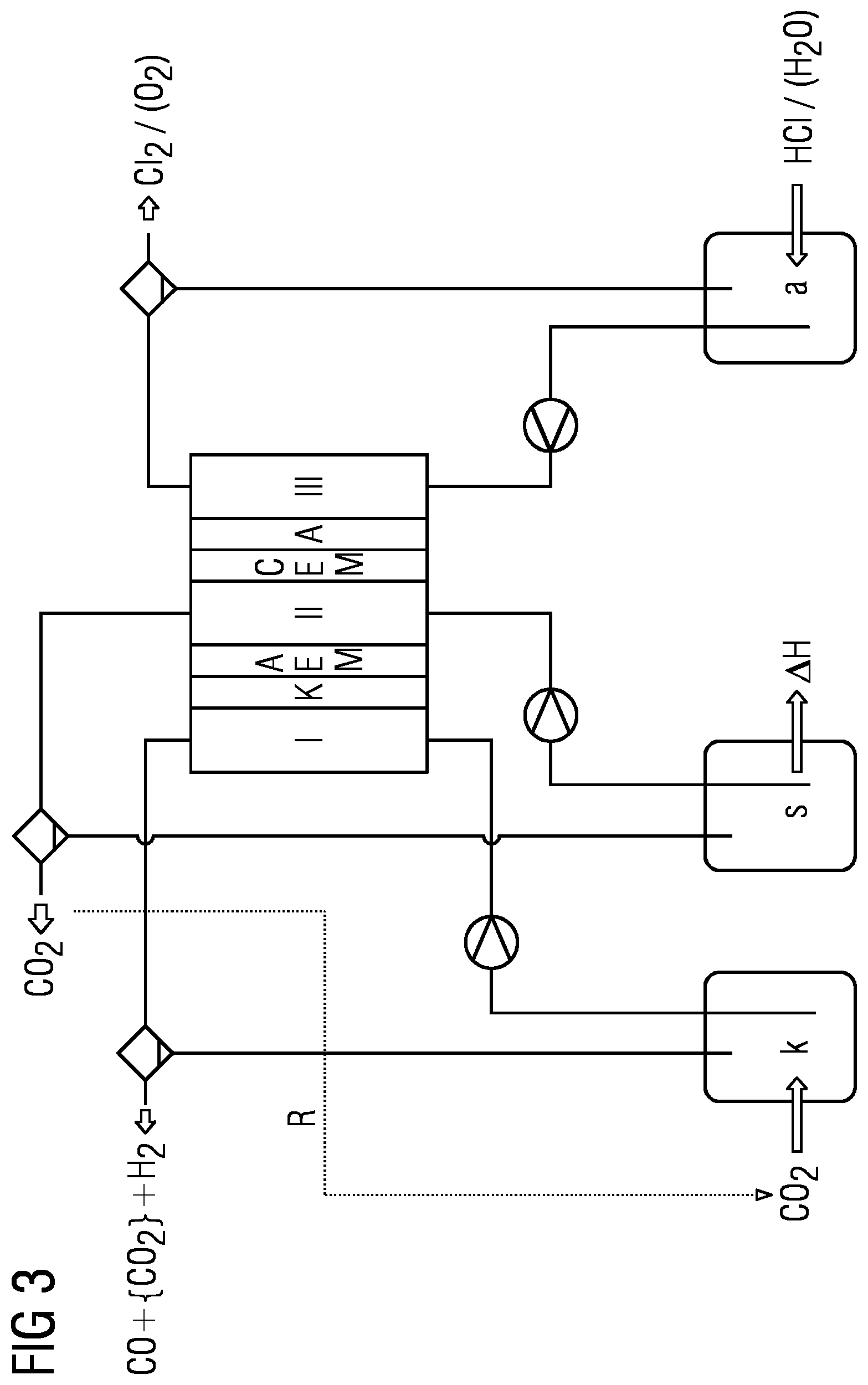
[0028] FIG. 3 shows a schematic of an example of an electrolysis system with an electrolysis cell as employed in some methods incorporating the teachings herein.
[0029] FIGS. 4 and 5 show schematics of further examples of electrolysis cells with which various methods incorporating the teachings herein may be executed.
[0030] FIGS. 6 and 7 show schematic graphic representations of the different release of CO.sub.2 in the case of use of a salt electrolyte (FIG. 6) and an acid electrolyte (FIG. 7).
[0031] FIG. 8 shows a schematic of an electrolysis system of the invention with an AEM diaphragm cell incorporating the teachings herein in which methods incorporating the teachings herein can be conducted.
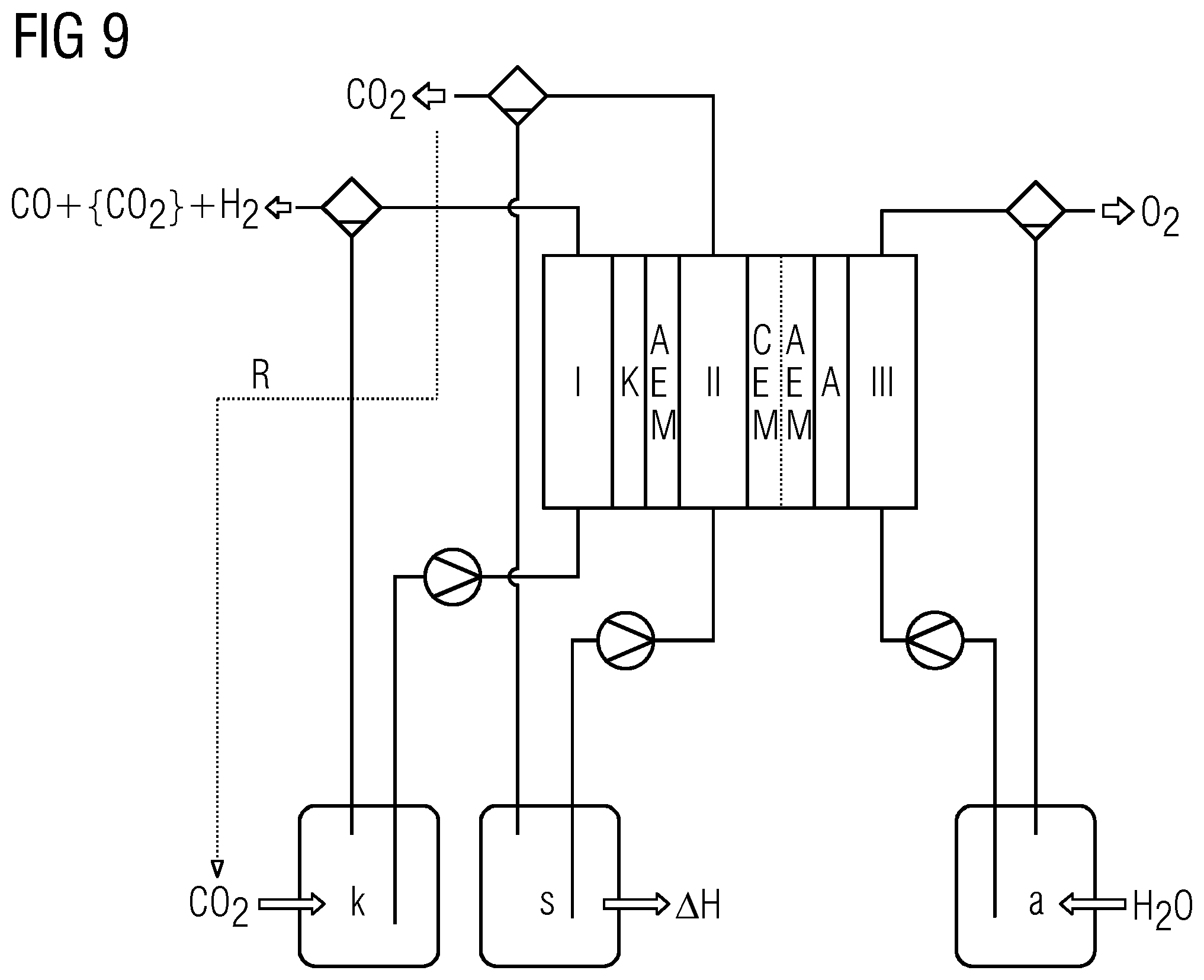
[0032] FIG. 9 shows a schematic diagram of an AEM bipolar double membrane cell in which methods incorporating the teachings herein can likewise be conducted.
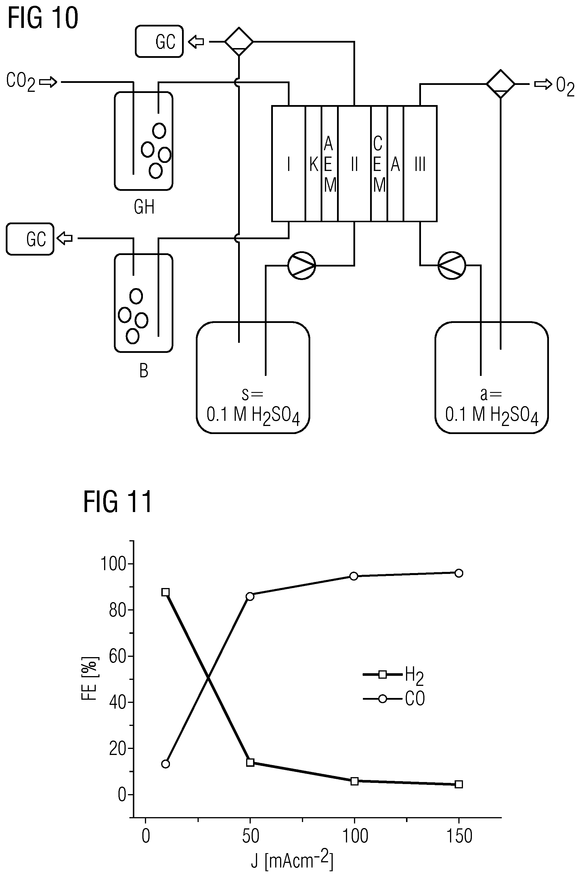
[0033] FIG. 10 shows a schematic of the experimental setup in example 1.
[0034] FIG. 11 shows experimental results of example 1, wherein the Faraday efficiency has been plotted against the current density applied.
[0035] FIG. 12 shows a schematic of the experimental setup in the present comparative example 1.
[0036] FIG. 13 shows the experimental results obtained thereby, again by a plot of the Faraday efficiency against the current density applied.
[0037] FIG. 14 compares the experimental results from example 1 (solid lines) with those from comparative example 1 (dotted lines).
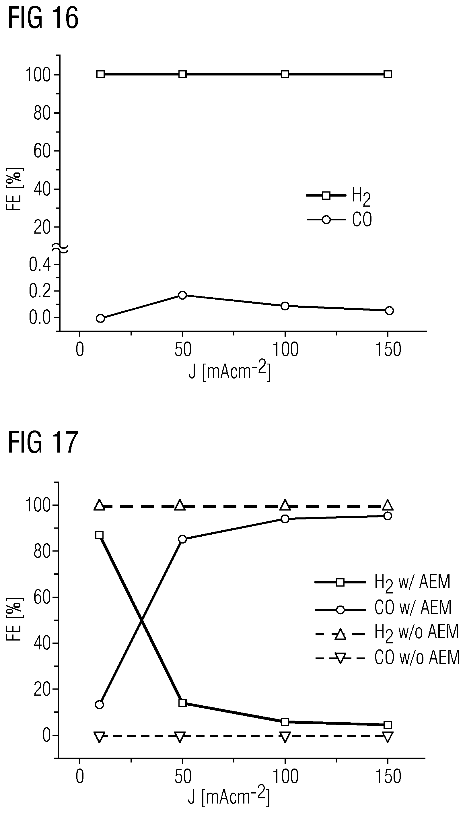
[0038] FIG. 15 shows a schematic diagram of the experimental setup in comparative example 2.
[0039] FIG. 16 shows the experimental results thus obtained, again by a plot of the Faraday efficiency against the current density applied.
[0040] FIG. 17 compares the experimental results from example 1 (solid lines) with those from comparative example 2 (dotted lines).
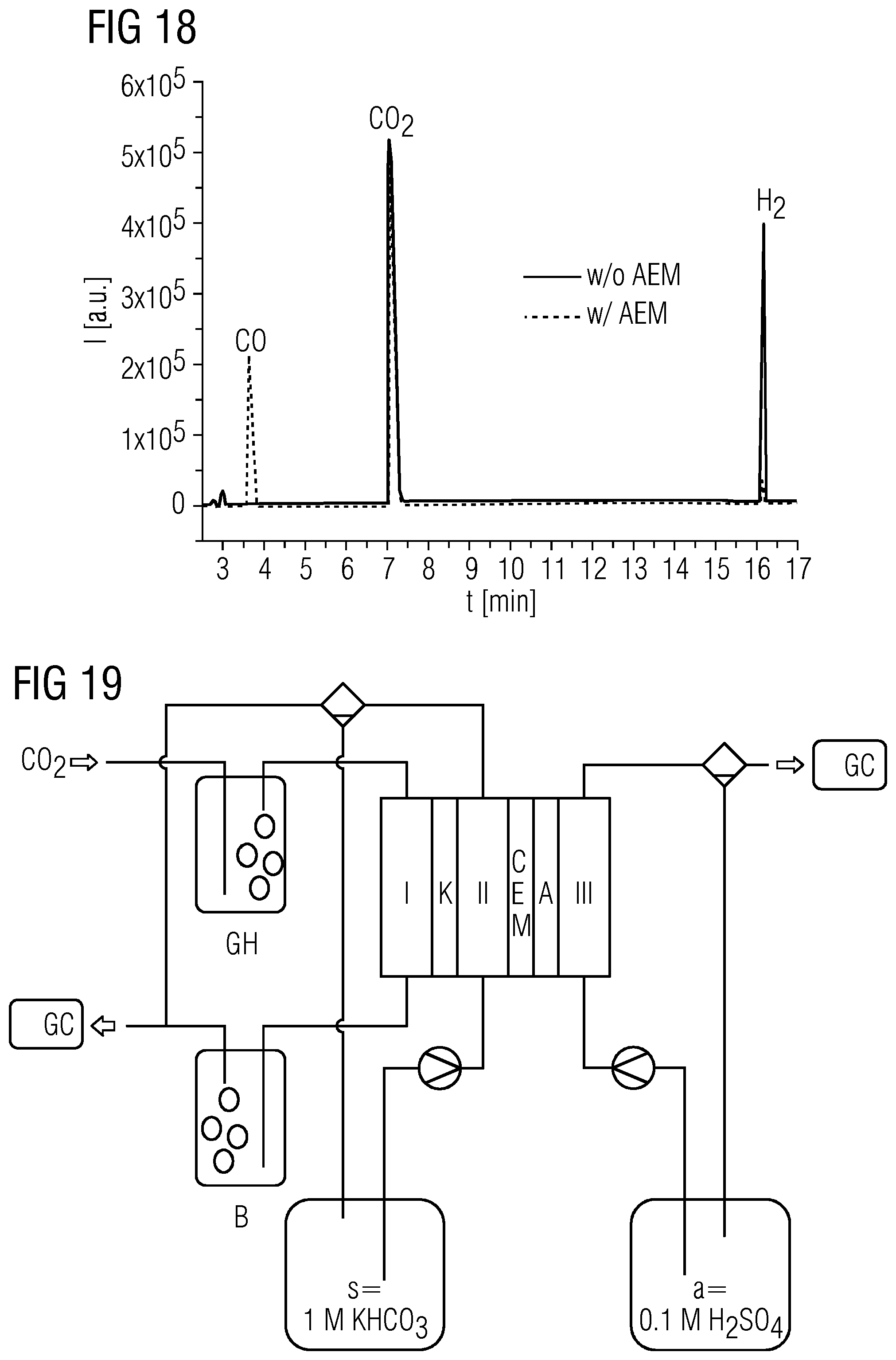
[0041] FIG. 18 shows a comparison of the gas chromatograms obtained in comparative example 2 (solid line; w/o AEM) and example 1 (dotted line; w/AEM) at a current density of 150 mAcm.sup.-2.
[0042] FIGS. 19 and 20 each show schematics of the experimental setup in reference examples 1 and 2.
[0043] FIGS. 21 and 22 show the experimental results obtained therein.
DETAILED DESCRIPTION
[0044] Given sufficiently high current densities, CO.sub.2 can be converted effectively in the presence of a liquid and/or dissolved acid at a membrane facing the cathode space and containing an anion exchanger and/or anion transporter, for example in a salt bridge space and/or in the anolyte, to products utilizable further in an economically viable manner, and the formation of hydrogen can surprisingly be suppressed. The elucidations that follow are applicable to the above systems, for example. On the basis of these considerations, it is possible to create a charge transport model for CO.sub.2 electrolysis as follows:
[0045] 1) Considerations for Salt Electrolytes
[0046] The cathodic reduction of CO.sub.2 to CO in the presence of water can be represented in a simplest approximation by the equation that follows, and analogous equations may also be adduced correspondingly in respect of the preparation of hydrocarbons from CO.sub.2:
CO.sub.2+H.sub.2O+2e.sup.-.fwdarw.CO+2OH.sup.- (1)
[0047] Since CO.sub.2 is typically available in excess in the 3-phase zone (although it may also be present in deficiency since the CO.sub.2 cannot be assigned to any particular catalyst site), the OH.sup.- ions formed can react therewith to give HCO.sub.3.sup.- ions.
OH.sup.-+CO.sub.2.fwdarw.HCO.sub.3.sup.- (2)
The result is:
3CO.sub.2+H.sub.2O+2e.sup.-.fwdarw.CO+2HCO.sub.3.sup.- (1 into 2)
[0048] This reaction has far-reaching consequences for charge transport within the porous electrode. Since HCO.sub.3.sup.-, by contrast with OH.sup.-, is not capable of charge transport via the Grotthuss mechanism, its molar conductivity is several times lower. Furthermore, it should be noted that the solubility of alkali metal hydrogencarbonates MHCO.sub.3 (M=Li, Na, K, Rb, Cs) is lower than that of the hydroxides of the alkali metals, which can result more quickly in unwanted crystallization of salts.
[0049] In CO.sub.2 electrolysis, however, electrolytes used are frequently solutions of alkali metal salts. The molar conductivity of HCO.sub.3.sup.- is only about half that of the alkali metal ions (M.sup.+ hereinafter), and therefore the majority of the charge transport in a region of the electrode where both the M.sup.+ ions of the electrolyte and the HCO.sub.3.sup.- ions generated at the cathode are present will be borne by the M.sup.+ ions. Owing to their low conductivity, in this case, the HCO.sub.3.sup.- ions generated at the cathode do not exit from the electrode into the electrolyte. Instead, the more mobile M.sup.+ ions penetrate into the electrode and form a salt with the HCO.sub.3.sup.- ions. This salt can then exit as a solution or permeate on the side of the electrode remote from the electrolyte. If, however, efficient removal of this MHCO.sub.3 solution is not insured, there can also be crystallization of these salts.
[0050] Over a prolonged period, this phenomenon leads to increasing penetration of the electrode by the electrolyte solution. This can result in irreversible pore flooding, which can lead to collapse of the CO.sub.2 supply of the electrode and hence to the failure thereof.
[0051] 2) Considerations for Solid-State Electrolytes
[0052] Solid-state electrolytes in electrolysis cells are, for example, membranes made from polymers modified with charged functionalities. Especially the usability of anion exchange membranes (AEMs) for CO.sub.2 electrolysis is known from the literature, for example from US 2016 0251755 A1, U.S. Pat. No. 9,481,939 and US 2017/0037522 A1.
[0053] In an AEM, the cationic functional groups are at fixed locations. In the absence of other ions, the charge transport in this case can therefore typically only be by HCO.sub.3.sup.- ions. However, this process can more particularly only be employed when the anode is also directly connected to the membrane. However, the supply of the HCO.sub.3.sup.- ions to the anode is undesirable since the CO.sub.2 formed there is released again by neutralization.
H.sub.2O-2e.sup.-.fwdarw.2H.sup.++1/2O.sub.2
HCO.sub.3.sup.-+H.sup.+.fwdarw.H.sub.2O+CO.sub.2
[0054] It is mixed here with the oxygen formed at the anode, and the result is a CO.sub.2/O.sub.2 mixture having a CO.sub.2 content of up to 80 mol % which is difficult to process or virtually unusable. As a result, in the case of CO, up to 67 mol % of the CO.sub.2 used may be lost unutilized. As described above, the considerations made above are also similarly applicable to other products from the CO.sub.2 reduction. In the case of products that derive from CO.sub.2 by reduction with more than two electrons, it is possible, for example, for a proportion of the CO.sub.2 used which is converted to hydrogen-carbonate to be correspondingly higher. For methane for example:
9CO.sub.2+8e.sup.-+6H.sub.2O.fwdarw.CH.sub.4+8HCO.sub.3.sup.-
14CO.sub.2+12e.sup.-+8H.sub.2O.fwdarw.C.sub.2H.sub.4+12HCO.sub.3.sup.-
[0055] In this case, for example, it is possible for up to 89 mol % of the CO.sub.2 used in the case of CH.sub.4 or 86 mol % in the case of C.sub.2H.sub.4 to be lost via the anode. If, on the other hand, a cathode-AEM composite is to be coupled to an anodic half-cell balanced with HCO.sub.3.sup.-, an electrolyte is again required. The aforementioned condition of the absence of other ions then no longer exists, and the charge transport is again also borne by ions other than the HCO.sub.3.sup.- ions, for example M.sup.+ ions in particular. Although the fixed cationic functional groups of the AEM repel the M.sup.+ ions, a counterion to M.sup.+ ions in the AEM is available in the form of the HCO.sub.3.sup.- ions.
[0056] Therefore, even within an AEM, a formal double salt system can exist in which, for example, the anionic part is taken entirely by HCO.sub.3.sup.-, while the cationic part is taken partly by M.sup.+ ions and partly by the cationic functional groups of the polymer. It is thus also possible for the penetration of M.sup.+ to be limited but not entirely prevented by an AEM in the presence of a salt electrolyte. In corresponding laboratory studies--as specified in comparative example 1 below--it was possible to observe crystallization of MHCO.sub.3 on the reverse side (gas side) of the electrode. However, the phenomenon is significantly attenuated compared to direct contact between cathode and electrolyte. The share of HCO.sub.3.sup.- in the charge transport can be distinctly increased compared to a mode of operation without AEM and can be determined, for example, to be .about.50 mol %, for example by CO.sub.2 measurement by gas chromatography, but is still limited. The cause of this is the low mobility of hydrogencarbonate anions as stated above and apparent from table 2 below, taken from Current Separations 18:3 (1999), Conductance Measurements, Part 1: Theory, Lou Coury, p. 91-96.
TABLE-US-00002 TABLE 20 Charge mobility of various ions Cation .lamda..sup.0.sub.+ (S cm.sup.2/mol) Anion .lamda..sup.0.sub.- (S cm.sup.2/mol) H.sup.+ 349.6 OH.sup.- 199.1 Li.sup.+ 38.7 F.sup.- 55.4 Na.sup.+ 50.10 Cl.sup.- 76.35 K.sup.+ 73.50 Br.sup.- 78.1 Rb.sup.+ 77.8 I.sup.- 76.8 Cs.sup.+ 77.2 NO.sub.2.sup.- 71.8 Ag.sup.+ 61.9 NO.sub.3.sup.- 71.46 NH.sub.4.sup.+ 73.5 ClO.sub.3.sup.- 64.6 Ethylammonium 47.2 ClO.sub.4.sup.- 67.3 Diethylammonium 42.0 IO.sub.4.sup.- 54.5 Triethylammonium 34.3 HCO.sub.3.sup.- 44.5 Tetraethylammonium 32.6 H.sub.2PO.sub.4.sup.- 57 Tetra-n-butylammonium 19.5 HSO.sub.3.sup.- 50 Dimethylammonium 51.8 HSO.sub.4.sup.- 50 Trimethylammonium 47.2 HC.sub.2O.sub.4.sup.- 40.2 Tetramethylammonium 44.9 HCOO.sup.- 54.6 Piperidinium 37.2 CH.sub.3COO.sup.- 40.9 Be.sup.2+ 90 C.sub.6H.sub.5COO.sup.- 32.4 Mg.sup.2+ 106.0 CO.sub.3.sup.2- 138.6 Ca.sup.2+ 119.0 HPO.sub.4.sup.2- 66 Sr.sup.2+ 118.9 SO.sub.4.sup.2- 160.0 Ba.sup.2+ 127.2 C.sub.2O.sub.4.sup.2- 148.2 Fe.sup.2+ 108.0 PO.sub.4.sup.3- 207 Cu.sup.2+ 107.2 Fe(CN).sub.6.sup.3- 302.7 Zn.sup.2+ 105.6 Fe(CN).sub.6.sup.4- 442.0 Pb.sup.2+ 142.0 UO.sub.2.sup.2+ 64 Al.sup.3+ 183 Fe.sup.3+ 204 La.sup.3+ 209.1 Ce.sup.3+ 209.4
[0057] 3) Considerations for Acidic Electrolytes:
[0058] CO.sub.2 electrolysis in aqueous electrolytes should actually not be thermodynamically possible since the breakdown voltage for the reaction
CO.sub.2.fwdarw.CO+1/2O.sub.2 1.32 V (3)
is higher than for the reaction:
H.sub.2O.fwdarw.H.sub.2+1/2O.sub.2 1.23 V (4)
[0059] The process is nevertheless possible under suitable conditions since, firstly, suitable catalysts have a high overvoltage for the water breakdown and, secondly, high local pH values can typically develop in the immediate proximity of the electrode at relatively high current densities. The latter effect typically requires a diffusion gradient where the OH.sup.-, CO.sub.3.sup.2- and HCO.sub.3.sup.- ions formed at the electrode displace the counterions of M.sup.+ ions from the electrolyte. Moreover, the M.sup.+ concentration in the immediate proximity of the electrode should be increased by attraction of the M.sup.+ ions by the electrical field. This can lower the water reduction potential, which suppresses the evolution of hydrogen. By contrast, the initial step in the CO.sub.2 reduction is not pH-dependent, which means that it dominates for longer.
[0060] However, if acids are added to the electrolyte, this gradient cannot form in sufficient intensity. In acidified electrolytes, therefore, typically only H.sub.2/CO mixtures with a large excess of H.sub.2 are obtained. In pure acid electrolytes, the CO.sub.2 reduction usually takes place only in the trace region. However, it should be mentioned at this point that the above-described passage of electrolytes through the electrode is not observed when pure acid electrolytes are used, as is also apparent from comparative example 2 below. The passage of electrolyte is accordingly caused, as discussed above, by the penetration of cations into the electrode. Since no cations are present in the present comparative example 2 and in the present working example, as is described further in detail below, there is no longer any passage of electrolyte either. The models discussed above can be confirmed thereby.
[0061] 4) Considerations for a Combination of an AEM and Pure Acid Electrolyte
[0062] An entirely different situation arises when an AEM is introduced between a pure acid electrolyte (e.g. H.sub.2SO.sub.4, as in working example 1). In this case, for example, even in a pure acid electrolyte, very good selectivities for CO>95% can be achieved at high current densities of >100 mAcm.sup.-2. The reason for this lies in a peculiarity of the carbonate-acid-base system. By contrast with other systems such as the sulfate system, there is no neutral acid in the carbonate equilibrium.
CO.sub.3.sup.2-HCO.sub.3.sup.-CO.sub.2+H.sub.2O
SO.sub.4.sup.-HSO.sub.4.sup.-H.sub.2SO.sub.4
[0063] Consequently, HCO.sub.3.sup.- cannot function as counterion for "H.sup.+", the only cations present in the electrolyte. It is thus not possible for a double salt situation to exist, as with alkali metal salt electrolytes. Presence of "H.sup.+" ions in the AEM is therefore possible only when the acid anions (e.g. SO.sub.4.sup.2-) of the electrolyte are also present in the AEM. If these are displaced from the AEM by a sufficiently high ion current, a high pH can be established in the cathode-AEM composite in spite of an acid electrolyte. The only other charge transport pathway is the conduction of OH.sup.- via the Grotthuss mechanism through the membrane swollen in H.sub.2O, or hopping transport of HCO.sub.3.sup.- from localized polymer-bound cation to localized cation.
[0064] Since, as already elucidated, the acid ions first have to be displaced from the AEM, exploitation of this effect requires a minimum current density. In the present working example this was about 50 mAcm.sup.-2; below this current density, almost exclusively H.sub.2 evolution was observed. At high current densities, the selectivity for CO was >90% and increased constantly with rising current density, as also shown in the working example hereinafter.
[0065] FIGS. 1 and 2 illustrate this difference in the use of various electrolytes 1 that adjoin the anion exchange membrane AEM, and which pass ions to the cathode K. In this context, FIG. 1 shows the variant with a salt M.sup.+X.sup.- as electrolyte 1 by way of example, whereas FIG. 2 shows the variant with an acid H+X.sup.- as electrolyte 1.
[0066] In some embodiments, the teachings of the present disclosure include a method of electrolysis of CO.sub.2, wherein an electrolysis cell comprising [0067] a cathode space comprising a cathode; [0068] a first ion exchange membrane which contains an anion exchanger and/or anion transporter and adjoins the cathode space, where the cathode forms direct contact with the first ion exchange membrane, the contact in particular embodiments additionally being ionic in nature; [0069] an anode space comprising an anode; [0070] a first separator membrane; and [0071] a salt bridge space, where the salt bridge space is disposed between the first ion exchange membrane and the first separator membrane, is used, wherein CO.sub.2 is reduced at the cathode, wherein the electrolyte in the salt bridge space consists of a liquid acid and/or a solution of an acid.
[0072] In some embodiments, a method of electrolysis of CO.sub.2, wherein an electrolysis cell comprising: [0073] a cathode space comprising a cathode; [0074] a first ion exchange membrane which contains an anion exchanger and/or anion transporter and adjoins the cathode space, where the cathode forms direct contact with the first ion exchange membrane, the contact in particular embodiments additionally being ionic in nature; and [0075] an anode space comprising an anode, where the anode space adjoins the first ion exchange membrane; is used, wherein CO.sub.2 is reduced at the cathode, wherein the electrolyte in the anode space consists of a liquid acid and/or a solution of an acid.
[0076] In some embodiments, an electrolysis cell comprises: [0077] a cathode space comprising a cathode; [0078] a first ion exchange membrane which contains an anion exchanger and/or anion transporter and adjoins the cathode space, where the cathode forms direct contact with the first ion exchange membrane; [0079] an anode space comprising an anode; and [0080] a diaphragm that adjoins the anode space;
[0081] further comprising a salt bridge space, wherein the salt bridge space is disposed between the first ion exchange membrane and the diaphragm, wherein the diaphragm is nonconductive.
[0082] In some embodiments, there is an electrolysis system comprising the electrolysis cell described above, and/or include the use of the electrolysis cell or of the electrolysis system for electrolysis of CO.sub.2.
Definitions
[0083] Unless defined differently, technical and scientific expressions used herein have the same meaning as commonly understood by a person skilled in the art in the technical field of the disclosure. Gas diffusion electrodes (GDE) in general are electrodes in which liquid, solid and gaseous phases are present, and where, in particular, a conductive catalyst catalyzes an electrochemical reaction between the liquid phase and the gaseous phase. They can be constructed in different ways, for example as a porous "all-active-material catalyst", optionally with auxiliary layers for adjustment of hydrophobicity, in which case it is possible to produce, for example, a membrane-GDE composite, e.g. AEM-GDE composite; as a conductive porous carrier to which a catalyst may be applied in a thin layer, in which case it is likewise again possible to produce a membrane-GDE composite, e.g. AEM-GDE composite; or as a catalyst which is porous in the composite and which may, optionally with additive, be applied directly to a membrane, e.g. an AEM, and in that case can form a CCM in the composite.
[0084] In the context of the present disclosure, "hydrophobic" is understood to mean water-repellent. Hydrophobic pores and/or channels are those that repel water. In particular, hydrophobic properties are associated in accordance with the invention with substances or molecules having nonpolar groups.
[0085] By contrast, "hydrophilic" is understood to mean the ability to interact with water and other polar substances.
[0086] In the application, figures given relate to % by weight, unless stated otherwise or apparent from the context.
[0087] Standard pressure is 101 325 Pa=1.01325 bar.
[0088] Electro-osmosis includes an electrodynamic phenomenon in which a force in the cathode direction acts on particles having a positive zeta potential that are present in solution, and a force in the anode direction on all particles having a negative zeta potential. If a conversion takes place at the electrodes, i.e. if there is galvanic current flow, there is also a stream of matter of the particles having positive zeta potential toward the cathode, irrespective of whether or not the species is involved in the conversion. The same is also true of a negative zeta potential and the anode. If the cathode is porous, the medium is also pumped through the electrode. This is also referred to as an electro-osmotic pump. The streams of matter that result from electro-osmosis can also flow counter to concentration gradients. Diffusion-related currents that compensate for the concentration gradients can be overcompensated as a result.
[0089] In some embodiments, methods of electrolysis of CO.sub.2, wherein an electrolysis cell comprising [0090] a cathode space comprising a cathode; [0091] a first ion exchange membrane which contains an anion exchanger and/or anion transporter and adjoins the cathode space, where the cathode forms direct contact with the first ion exchange membrane; [0092] an anode space comprising an anode; [0093] a first separator membrane; and [0094] a salt bridge space, where the salt bridge space is disposed between the first ion exchange membrane and the first separator membrane, is used, wherein CO.sub.2 is reduced at the cathode, wherein the salt bridge space includes a liquid acid and/or a dissolved acid. In some embodiments, the electrolyte in the salt bridge space consists of the liquid acid and/or the solution of an acid--for example a solid or gaseous acid, for example in water, e.g. double-distilled or demineralized water.
[0095] In some embodiments, methods of electrolysis of CO.sub.2, wherein an electrolysis cell comprising [0096] a cathode space comprising a cathode; [0097] a first ion exchange membrane which contains an anion exchanger and/or anion transporter and adjoins the cathode space, where the cathode forms direct contact with the first ion exchange membrane; and [0098] an anode space comprising an anode, where the anode space adjoins the first ion exchange membrane; is used, wherein CO.sub.2 is reduced at the cathode, wherein the anode space includes a liquid acid and/or a dissolved acid. In some embodiments, the electrolyte in the anode space consists of the liquid acid and/or the solution of an acid--for example a solid or gaseous acid, for example in water, e.g. double-distilled or demineralized water.
[0099] In order to illustrate the similarities and differences in the methods in advance, these are illustrated by figures beforehand, although the methods are not limited to the embodiments shown in these figures. The individual constituents of the cells used in the methods described herein, and also of the cell in which the methods can be conducted, are then disclosed in detail thereafter.
[0100] Illustrative different modes of operation of a double-membrane cell and a single-membrane cell with which the methods of the invention can be conducted are shown in FIGS. 3 to 5--in FIG. 3 also in conjunction with further constituents of an electrolysis system, also with regard to the method of the invention. In the figures, by way of example, a reduction of CO.sub.2 to CO is assumed. In principle, however, the method is not limited to this reaction but can also be used for any other products, such as hydrocarbons, etc., e.g. in gaseous and/or liquid form.
[0101] FIG. 3 shows, by way of example, a 2-membrane setup for CO.sub.2 electroreduction with an acidic anode reaction. In each case here, the cathode K is provided in the cathode space I and the anode A in the anode space III, with a salt bridge space II formed between these spaces, which is divided from the cathode space I by a first ion exchange membrane, here in the form of an AEM, and from the anode space III by a first separator membrane, here in the form of a CEM, for example in the form of a cation and/or proton exchange membrane. Additionally shown are the feed of catholyte k to supply the cathode with substrate, for example H.sub.2O-saturated gaseous CO.sub.2, electrolyte s in the salt bridge space comprising liquid and/or dissolved acid that couples the half-cells to one another, and anolyte a for supply of the anode with substrate, e.g. HCl and/or H.sub.2O, and also a recycle conduit R for CO.sub.2. The further symbols in FIG. 3 and also in the analogous FIGS. 8, 9, 10, 12, 15, 19 and 20 are customary fluidic connection symbols.
[0102] By contrast with the use of a neutral to weakly basic salt electrolyte as salt bridge s, it is possible by the present method in the first aspect to neutralize cathodically generated HCO.sub.3.sup.- at the interface between the anion exchange membrane (AEM) and the salt bridge electrolyte. This can prevent HCO.sub.3.sup.- from getting to the anode and subsequently being lost as unusable CO.sub.2/O.sub.2 mixture. Thus, in particular embodiments, virtually pure CO2 with just minimal traces of cathodic products is released in the salt bridge space, and can be sent directly back to the cathode space I.
[0103] FIGS. 4 and 5 additionally show further constructions of an electrolysis cell as can be employed in a method incorporating the teachings herein. No salt bridge space is provided in the two-chamber setup, and so the anode space III directly adjoins the AEM, and it is possible here for the anode, as shown in FIGS. 4 and 5, to be present anywhere in the anode space III. Corresponding configurations of the anode space are also possible in a method having a set up as shown in FIG. 3, where the anode A thus does not adjoin the CEM. The electrolysis cells shown in FIGS. 4 and 5 can likewise be used in the electrolysis system shown in FIG. 3. It is also possible for the different half-cells from FIGS. 3 to 5 and also the corresponding arranged constituents of the electrolysis system to be combined as desired, and likewise also with other electrolysis half-cells (not shown). As apparent from FIGS. 3 to 5, it is a feature of the methods taught herein that the cathode K forms direct, especially also ionic, contact with the first ion exchange membrane containing an anion exchanger and/or anion transporter. In addition, the space adjoining the first ion exchange membrane--either the salt bridge space II in FIG. 3 or the anode space III in FIGS. 4 and 5--contains a liquid and/or dissolved acid.
[0104] The methods herein have the particular feature of the use of a liquid and/or dissolved acid in the salt bridge space or in the anode space, specifically by comparison with strongly acidic ion exchanger packages or similar solid apparatuses:
[0105] Firstly, gas bubbles that form from the reaction in the salt bridge space or anode space can be transported away unhindered through the fluid medium, which enables a simple mode of operation.
[0106] Moreover, it is possible here to choose higher flow rates in order to be able to assure better cooling of the system.
[0107] Furthermore, in the case of use of liquid and/or dissolved acids, simpler and less costly operation is of course also possible, especially by comparison with ion exchangers.
[0108] In addition, in the case of use of liquid and/or dissolved acids, accumulation of metal impurities in parts of the electrolysis cell can be avoided in that they are washed out by the liquid and/or dissolved acid.
[0109] Correspondingly, external electrolyte treatment, for example with a cation exchanger, is subsequently possible. This is especially a great difference from US 2017/0037522 A1, in which an empty or ion exchanger-packed middle chamber is disclosed.
[0110] The salt bridge space or the anode space, depending on the embodiment, are not particularly restricted provided that they correspondingly adjoin the first ion exchange membrane. The term "salt bridge space" is used here with regard to its function of acting as a bridge between the anode arrangement and cathode arrangement, and in that respect of including cations and anions which, however, need not necessarily form salts in the present context. Since a liquid or dissolved acid is present in the salt bridge space in the present context, this could also be called acid bridge space or ion bridge space. However, since this term is not in common use, the space is referred to in accordance with the disclosure as salt bridge space even if no salt need be present therein in the conventional sense. In some embodiments, there is an electrolyte in the salt bridge space--if present--that can assure electrolytic ionic connection between cathode arrangement and anode arrangement. This electrolyte is also referred to as salt bridge and includes a liquid and/or dissolved acid.
[0111] The salt bridge thus serves here as electrolyte, preferably with high ion conductivity, and serves to establish contact between the anode and cathode. In some embodiments, the salt bridge also enables the removal of waste heat. Moreover, the salt bridge can serve as reaction medium for the anodically and cathodically generated ions such as protons or hydroxide or hydrogencarbonate ions.
[0112] The technical teaching consists in the construction and operation of the cathodic half-cell. The latter consists of a gas-permeable electrically connected catalyst layer in direct contact with an AEM, the opposite face of which is adjoined by an acid-based electrolyte, preferably without alkali metal cations, especially without metal cations. The acid here is not particularly restricted, provided that it is in the form of a liquid and/or in solution, i.e. the acid is able to flow through the salt bridge space and/or the anode space. In some embodiments, the acid is water-soluble and/or is in the form of a solution in a suitable solvent such as water, alcohols, aldehydes, esters, carbonates, etc., and/or mixtures, especially water, e.g. double-distilled or demineralized water.
[0113] In some embodiments, an acid in the electrolyte in the salt bridge space has a pK.sub.A of 6 or less, 5 or less, 3 or less, 1 or less, or 0 or less, where the liquid and/or dissolved acid may be selected from dilute or neat H.sub.2SO.sub.4, a solution of H.sub.2N--SO.sub.2--OH, dilute or neat HClO.sub.4, a solution of H.sub.3PO.sub.4, dilute or neat CF.sub.3--COOH, dilute or neat CF.sub.3--SO.sub.2--OH, a solution of (CF.sub.3--SO.sub.2).sub.2--NH, a solution of HF, dilute or neat HCOOH, dilute or neat CH.sub.3--COOH, a solution of HCl, a solution of HBr, a solution of HI, and/or mixtures thereof.
[0114] In some embodiments, the acid electrolyte is notable for the absence of mobile cations--as will be defined further down, especially metal cations, except for "H.sup.+" or "D.sup.+". Rather than H.sup.+ or D.sup.+, reference is made hereinafter solely to H.sup.+ or protons. The electrolyte thus may not contain any mobile cations except for "H.sup.+", especially any metal cations. In the working example of the disclosure, sulfuric acid, especially dilute sulfuric acid (H.sub.2SO.sub.4), was used, which, owing to its low cost and its high conductivity, works as a liquid and/or dissolved acid. In some embodiments, it is also possible to use other acids, as set out above, e.g. strong acids with nonoxidizing anions such as H.sub.2N--SO.sub.2--OH, HClO.sub.4, H.sub.3PO.sub.4, CF.sub.3--COOH, CF.sub.3--SO.sub.2--OH, (CF.sub.3--SO.sub.2).sub.2--NH, etc. It is also possible to use weak acids in relatively high concentrations, for example greater than 10% or 20% by weight, for example greater than 30% by weight, or at their respective conductivity maximum, e.g. HF, HCOOH, CH.sub.3--COOH. In some embodiments, this acid is identical to the cathodic product from the CO.sub.2 electrolysis, for example in the case of formic acid or acetic acid. In some embodiments, the acids may be present in a concentration up to 30% by weight, up to 50% by weight, up to 70% by weight, or up to 100% by weight. It is also possible to use other acids, especially in the case of demonstrable compatibility with the electrode catalysts, for example dissolved HCl, HBr, HI.
[0115] In some embodiments, a salt electrolyte typically adjoining the first ion exchange membrane, for example in the salt bridge space or in the anode space, may be replaced by an acid. In the presence of a salt bridge space, the advantage of the CO.sub.2-free anode and the partial removal of the CO.sub.2 excess in the salt bridge space continues to exist, as shown in schematic form in FIGS. 6 and 7. By contrast with the use of a salt electrolyte 2 in the salt bridge space, as shown in FIG. 6, however, the CO.sub.2 is released not at the interface between CEM and electrolyte but, as shown in FIG. 7, at the interface between AEM and acid 3. In FIGS. 6 and 7, an acid is also present here in the anode space.
[0116] Since acids are used both for the anolyte and for the salt bridge in the variant shown, it is also possible to choose these with identical composition. Since no osmotic pressures occur in this case and the release of the CO.sub.2 can also take place before the salt bridge, especially in the region of the first ion exchange membrane and hence away from the first separator membrane, if present, in which case the HCO.sub.3.sup.- no longer reaches the first separator membrane in particular embodiments, it is no longer absolutely necessary to use an ion-selective membrane as first separator membrane, and it is also possible, for example, to use a diaphragm in order to separate CO.sub.2 and O.sub.2. Correspondingly, a diaphragm is also possible as the first separator membrane, as detailed further hereinafter, and is consequently also possible to use a corresponding electrolysis cell of the invention, for example an AEM diaphragm cell--as detailed further hereinafter--in the method of the invention.
[0117] It should be noted that it is possible in principle to pump anolyte and salt bridge out of a common reservoir, in which case reliable degassing of the electrolytes may be ensured, in order not to entrain any gases. This is possible particularly efficiently owing to the low solubility of CO.sub.2 in the acid-based electrolyte. In some embodiments, methods are therefore conducted at relatively high temperatures in the range of 50-120.degree. C., or between 60-90.degree. C., in order to further minimize gas solubility.
[0118] In some embodiments, the acid concentration may be chosen such that it lies at the conductivity maximum of the acid. It is possible here for the conductivity, especially for sulfuric acid (3 mol/1=.about.30%) to be almost an order of magnitude higher than that which can be achieved by salt concentrations that are similarly high but at the saturation limit (1-2 mol/1). Illustrative conductivities are shown in tables 3 and 4 for sulfuric acid and phosphoric acid.
TABLE-US-00003 TABLE 3 Electrical conductivity of sulfuric acid (and oleum) at 25.degree. C. (from Konduktometrie - Leitfahigkeitsmessung [Conductometry - Conductivity Measurement], Peter Bruttel, revised by Dr. Christine Thielen, Dr. Anja Zimmer, Metrohm AG, Switzerland, page 37) % Conductivity % Conductivity H.sub.2SO.sub.4 [mS/cm] H.sub.2SO.sub.4 (SO.sub.3) [mS/cm] 3.93 177 53.5 555 7.00 308 58.4 471 10.0 426 63.1 380 14.6 586 72.3 223 19.8 717 85.9 124 25.3 796 95.4 124 29.4 825 98.0 94.7 34.3 819 100.0 10.46 39.1 781 101.5 32.05 43.9 714 103.8 34.50 48.7 640 105.1 28.84 M(H.sub.2SO.sub.4) = 98.07 g/mol M(SO.sub.3) = 80.06 g/mol
TABLE-US-00004 TABLE 4 Electrical conductivity of phosphoric acid at 25.degree. C. (from Konduktometrie - Leitfahigkeitsmessung, Peter Bruttel, revised by Dr. Christine Thielen, Dr. Anja Zimmer, Metrohm AG, Switzerland, page 37) % H.sub.3PO.sub.4 Conductivity [mS/cm] 5 31 10 61 15 91 20 722 25 152 30 180 35 204 40 222 45 232 50 233 55 224 60 210 70 169 80 98 M(H.sub.3PO.sub.4) = 97.995 g/mol
[0119] The individual constituents of an electrolysis cell used in the methods and of the electrolysis cell will now be described and disclosed further. In some embodiments, the cathode space, the anode space and any salt bridge space present, in the methods and also in the electrolysis cell discussed hereinafter, are not particularly restricted in terms of shape, material, dimensions, etc., provided that they can accommodate the cathode, the anode and the first ion exchange membrane and any first separator membrane. The two or three spaces may be formed, for example, within a common cell, in which case they may be separated correspondingly by the first ion exchange membrane and optionally the first separator membrane.
[0120] For the individual spaces, it is possible here, according to the electrolysis to be conducted, to correspondingly provide inlet and outlet devices for reactants and products, for example in the form of liquid, gas, solution, suspension, etc., where these may optionally also each be recycled. Nor is there any restriction in this regard, and the flow through the individual spaces may be in parallel streams or in countercurrent. For example, in the case of electrolysis of CO.sub.2-- where this may still contain CO, i.e., for example, contains at least 20% by volume of CO.sub.2-- this may be supplied to the cathode in solution, as a gas, etc.--for example in countercurrent to an electrolyte stream in the salt bridge space in the three-chamber setup or in the anode space in a two-chamber setup (without first separator membrane). There is no restriction in this regard.
[0121] Corresponding feed options also exist for the anode space and will also be set out in more detail hereinafter. The respective feed may be provided either in continuous or discontinuous form, for example in pulsed form, etc., for which pumps, valves, etc. may correspondingly be provided in an electrolysis system of the invention, and also cooling and/or heating devices, in order to be able to correspondingly catalyze desired reactions at the anode and/or cathode. The materials of the respective spaces or of the electrolysis cell and/or of the further constituents of the electrolysis system may also be suitably adapted here to desired reactions, reactants, products, electrolytes, etc. Furthermore, at least one power source per electrolysis cell is of course also included. Further apparatus parts that may occur in electrolysis cells or electrolysis systems may be provided in the electrolysis system of the invention or the electrolysis cell. In some embodiments, these individual cells are used to construct a stack comprising 2-1000 or 2-200 cells and the operating voltage thereof may be in the range of 3-1500 V or 200-600 V.
[0122] In some embodiments, a reactant gas formed in the salt bridge space, for example CO.sub.2 that may also contain H.sub.2 and/or CO, is recycled back in the direction of the cathode space.
[0123] In some embodiments, the cathode is not particularly restricted and may be matched to a desired half-reaction, for example with regard to the reaction products, in that it forms direct contact with the first ion exchange membrane, i.e. is in direct contact with the first ion exchange membrane at at least one point, wherein the cathode is in direct contact essentially in two dimensions with the first ion exchange membrane. The cathode thus directly adjoins the first ion exchange membrane at least in one region.
[0124] A cathode for reduction of CO.sub.2 and optionally CO may include, for example, a metal such as Cu, Ag, Au, Zn, Pb, Sn, Bi, Pt, Pd, Ir, Os, Fe, Ni, Co, W, Mo, etc., or mixtures and/or alloys thereof, e.g. Cu, Ag, Au, Zn, Pb, Sn, or mixtures and/or alloys thereof, and/or a salt thereof, where suitable materials may be matched to a desired product. The catalyst may thus be chosen according to the desired product. In the case of the reduction of CO.sub.2 to CO, for example, the catalyst may be based on Ag, Au, Zn and/or compounds thereof, such as Ag.sub.2O, AgO, Au.sub.2O, Au.sub.2O.sub.3, ZnO. For preparation of hydrocarbons, Cu or Cu-containing compounds such as Cu.sub.2O, CuO and/or copper-containing mixed oxides with other metals, etc. may be used. For a preparation of formic acid, for example, catalysts based on Pb and/or Cu, especially Cu, are possible. Since the formation of hydrogen can be entirely suppressed by the ion transport at high current densities, it is also possible to use catalysts for CO.sub.2 reduction that do not have a high overvoltage with respect to hydrogen, for example reduction catalysts such as Pt, Pd, Ir, Os or carbonyl-forming metals such as Fe, Ni, Co, W, Mo. Thus, the mode of operation described in conjunction with the cell design opens up new routes in CO.sub.2 reduction chemistry that do not depend on the hydrogen overvoltage.
[0125] The cathode is the electrode at which the reductive half-reaction takes place. It may be in single-part or multipart form and take the form, for example, of a gas diffusion electrode, porous electrode, or be directly in a composite with the AEM, etc. At least the following embodiments, for example, are possible here: [0126] gas diffusion electrode or porous bound catalyst structure which, in particular embodiments, may be bonded to the first ion exchange membrane, for example an anion exchange membrane (AEM), for example in an ion-conducting and/or mechanical manner, by means of a suitable ionomer, for example an anionic ionomer; [0127] gas diffusion electrode or porous bound catalyst structure which, in particular embodiments, may have been pressed partially into the first ion exchange membrane, for example an AEM; [0128] porous, conductive, catalytically inactive structure, e.g. carbon-paper GDL (gas diffusion layer), carbon-cloth GDL and/or polymer-bound film of granular glassy carbon impregnated with the catalyst for the cathode and optionally an ionomer that enables the binding to the first ion exchange membrane, for example an AEM, in which case the electrode may have been pressed mechanically onto the first ion exchange membrane, for example an AEM, or pressed beforehand with the first ion exchange membrane, for example an AEM, in order to form a composite; [0129] particulate catalyst that has been applied by means of a suitable ionomer to a suitable carrier, for example a porous conductive carrier, and in particular embodiments may adjoin the first ion exchange membrane, for example an AEM; [0130] particulate catalyst that has been pressed into or coated onto the first ion exchange membrane, for example an AEM, and correspondingly bonded in an electrically conductive manner, for example, in which case this structure may be pressed, for example, as what is called a CCM (catalyst-coated membrane) onto a conductive porous electrode, where catalytic activity of this electrode is not required in principle and, for example, it is possible to use carbon-based GDLs or grids, for example of titanium, and it is not ruled out here that this electrode contains or consists in large portions of ionomers and/or the active catalyst; [0131] noncontinuous sheetlike structure, for example a mesh or an expanded metal, which, for example, consists of or comprises or has been coated with a catalyst and, in particular embodiments, adjoins the first ion exchange membrane, for example an AEM; [0132] polymer-bound all-active catalyst structure composed of particulate catalyst that contains or has subsequently been impregnated with an ionomer that enables binding to the first ion exchange membrane, for example an AEM, in which case the electrode may be mechanically pressed onto the first ion exchange membrane, for example an AEM, or have been pressed beforehand with the first ion exchange membrane, for example an AEM, in order to form a composite; [0133] porous conductive carrier that has been impregnated with a suitable catalyst and optionally an ionomer and, in particular embodiments, adjoins the first ion exchange membrane, for example an AEM; [0134] non-ion-conductive gas diffusion electrode that has been subsequently impregnated with a suitable ionomer, for example an anion-conductive ionomer, and, in particular embodiments, adjoins the first ion exchange membrane, for example an AEM, or has been bonded thereto, for example via an ionomer.
[0135] Various combinations of the above-described electrode structures are also possible as cathode. The corresponding cathodes here too may contain materials that are customary in cathodes, such as binders, ionomers, for example anion-conductive ionomers, fillers, hydrophilic additives, etc., which are not particularly restricted. As well as the catalyst, the cathode may thus, in particular embodiments, contain at least one ionomer, for example an anion-conductive or anion-transporting ionomer (e.g. anion exchange resin, anion transport resin) that may comprise, for example, various functional groups for ion exchange that may be the same or different, for example tertiary amine groups, alkyl ammonium groups and/or phosphonium groups, a carrier material, for example a conductive carrier material (e.g. a metal such as titanium), and/or at least one nonmetal such as carbon, Si, boron nitride (BN), boron-doped diamond, etc., and/or at least one conductive oxide such as indium tin oxide (ITO), aluminum zinc oxide (AZO) or fluorinated tin oxide (FTO)--for example as used for production of photoelectrodes, and/or at least one polymer based on polyacetylene, polyethoxythiophene, polyaniline or polypyrrole, as, for example, in polymer-based electrodes; nonconductive carriers, for example polymer meshes, are possible given adequate conductivity of the catalyst layer, binders (e.g. hydrophilic and/or hydrophobic polymers, e.g. organic binders, for example selected from PTFE (polytetrafluoroethylene), PVDF (polyvinylidene difluoride), PFA (perfluoroalkoxy polymers), FEP (fluorinated ethylene-propylene copolymers), PFSA (perfluorosulfonic acid polymers), and mixtures thereof, especially PTFE), conductive fillers (e.g. carbon), nonconductive fillers (e.g. glass) and/or hydrophilic additives (e.g. Al.sub.2O.sub.3, MgO.sub.2, hydrophilic materials such as polysulfones, e.g. polyphenylsulfones, polyimides, polybenzoxazoles or polyetherketones, or generally polymers that are electrochemically stable in the electrolyte, polymerized "ionic liquids", and or organic conductors such as PEDOT:PSS or PANI (camphorsulfonic acid-doped polyaniline), which are not particularly restricted.
[0136] The cathode, e.g. in the form of a gas diffusion electrode, for example bonded to the first ion exchange membrane, or present in the form of a CCM, in particular embodiments, contains ion-conductive components, especially an anion-conductive component. Other cathode forms are also possible, for example cathode constructions as described in US2016 0251755-A1 and U.S. Pat. No. 9,481,939.
[0137] The anode is not particularly restricted either and may be matched to a desired half-reaction, for example with regard to the reaction products. At the anode, which is electrically connected to the cathode by means of a power source to provide the voltage for the electrolysis, the oxidation of a substance takes place in the anode space. Furthermore, the anode material is not particularly restricted and depends primarily on the reaction desired. Illustrative anode materials include platinum or platinum alloys, palladium or palladium alloys, and glassy carbon, iron, nickel etc.
[0138] Further anode materials are also conductive oxides such as doped or undoped TiO.sub.2, indium tin oxide (ITO), fluorine-doped tin oxide (FTO), aluminum-doped zinc oxide (AZO), iridium oxide, etc. optionally, these catalytically active compounds may also have been merely superficially applied by thin-film methodology, for example on a titanium and/or carbon carrier. The anode catalyst is not particularly restricted. Catalysts used for production of O.sub.2 or Cl.sub.2 also include, for example, IrO.sub.x (1.5<x<2) or RuO.sub.2. These may also be in the form of a mixed oxide with other metals, e.g. TiO.sub.2, and/or have been supported on a conductive material such as C (in the form of conductive carbon black, activated carbon, graphite, etc.). Alternatively, it is also possible to utilize catalysts based on Fe--Ni or Co--Ni for production of O.sub.2. For this purpose, for example, the construction described below with a bipolar membrane is suitable.
[0139] The anode is the electrode at which the oxidative half-reaction takes place. It may likewise take the form of a gas diffusion electrode, porous electrode or all-active electrode or solid electrode, etc. At least the following embodiments are possible: [0140] gas diffusion electrode or porous bound catalyst structure which, in particular embodiments, may be bonded to the first separator membrane, if present, for example a cation exchange membrane (CEM) or a diaphragm, for example in an ion-conducting and/or mechanical manner, by means of a suitable ionomer, for example a cationic ionomer; [0141] gas diffusion electrode or porous bound catalyst structure which, in particular embodiments, may have been pressed partially into the first separator membrane, for example a CEM or a diaphragm; [0142] particulate catalyst that has been applied by means of a suitable ionomer to a suitable carrier, for example a porous conductive carrier, and in particular embodiments may adjoin the first separator membrane, for example a CEM or a diaphragm; [0143] particulate catalyst that has been pressed into the first separator membrane, for example a CEM or a diaphragm, and correspondingly bonded in an electrically conductive manner, for example; [0144] noncontinuous sheetlike structure, for example a mesh or an expanded metal, which, for example, consists of or comprises or has been coated with a catalyst and, in particular embodiments, adjoins the first separator membrane, for example a CEM or a diaphragm; [0145] solid electrode, in which case there may also be a gap between the first separator membrane, for example a CEM or a diaphragm, and the anode, although this is not preferred; [0146] porous conductive carrier that has been impregnated with a suitable catalyst and optionally an ionomer and, in particular embodiments, adjoins the first separator membrane, for example a CEM or a diaphragm; [0147] non-ion-conductive gas diffusion electrode that has been subsequently impregnated with a suitable ionomer, for example a cation-conductive ionomer, and, in particular embodiments, adjoins the first separator membrane, for example a CEM or a diaphragm; [0148] any desired variants of the embodiments discussed, where the electrode contains, for example, an anodically stable anion-conductive material and directly adjoins the anion-conductive layer of a bipolar membrane.
[0149] The anode here may follow on from the acid electrolyte or else directly adjoin the first ion exchange membrane, for example an AEM, for example in the form of a sheetlike structure (e.g. fine-mesh coated grid), such that there is no salt bridge space. Here too, various combinations of the different anode structures are possible. In some embodiments, the cathode is coupled to the anodic half-cell via the liquid acid, for example in the salt bridge space or in the anode space, for example in the salt bridge space.
[0150] The corresponding anodes may likewise contain materials that are customary in anodes, such as binders, ionomers, for example including cation-conducting ionomers, for example containing sulfonic acid and/or phosphonic acid groups, fillers, hydrophilic additives, etc., which are not particularly restricted, which have also been described above, for example, with regard to the cathodes.
[0151] In some embodiments, it is possible to combine the electrodes mentioned by way of example above with one another as desired. Furthermore, it is also possible for electrolyte to be present in the anode space and cathode space, which are also respectively referred to as anolyte and catholyte, but it is not ruled out in that no electrolytes are present in the two spaces and they are correspondingly supplied, for example, solely with gases for conversion, for example CO.sub.2 only, optionally also as a mixture with, for example, CO and/or H.sub.2O, which may optionally also be in liquid form, for example as an aerosol, but with gaseous H.sub.2O to the cathode and/or water or HCl to the anode. In some embodiments, an anolyte is present, which may differ from or correspond to the salt bridge, i.e. the electrolyte of the salt bridge space, which includes a liquid and/or dissolved acid--if present, for example with regard to solvents, acids present, etc. If no salt bridge is present, the anolyte comprises a liquid and/or dissolved acid.
[0152] A catholyte here is the electrolyte flow around the cathode and, in particular embodiments, serves to supply the cathode with substrate or reactant. The embodiments which follow are possible, for example. The catholyte may take the form, for example, of a solution of the substrate (CO.sub.2) in a liquid carrier phase (e.g. water) and/or of a mixture of the substrate with other gases (e.g. CO+CO.sub.2; water vapor+CO.sub.2). It is likewise possible for recycled gases such as CO and/or H.sub.2 to be present as a result of recycling. It is also possible as described above, for the substrate to be present as a pure phase, e.g. CO.sub.2. If the reaction gives rise to uncharged liquid products, these may be washed out by the catholyte and may subsequently also optionally be removed in a corresponding manner.
[0153] An anolyte is an electrolyte flow around the anode or at the anode and, in particular embodiments, serves to supply the anode with substrate or reactant and optionally to transport anode products away. The embodiments that follow are possible, for example. The anolyte may take the form of a solution of the substrate (e.g. hydrochloric acid=HCl.sub.aq) in a liquid carrier phase (e.g. water), optionally with conductive salts that are not restricted--especially in the case of use of a bipolar membrane as the first separator membrane, where the anolyte here may also be basic and may also contain cations, as described above, or of a mixture of the substrate with other gases (e.g. hydrogen chloride=HCl.sub.g+H.sub.2O, SO.sub.2, etc.). As is also the case for the catholyte, however, the substrate may also take the form of a pure phase, for example in the form of hydrogen chloride gas=HCl.sub.g.
[0154] In some embodiments, the anode space comprises an anolyte comprising a liquid and/or dissolved acid, preferably wherein the anolyte and/or the acid in the salt bridge space or the electrolyte in the salt bridge space does not include any mobile cations except for protons and/or deuterons, especially any metal cations. In some embodiments, the acid in the salt bridge space does not comprise any mobile cations except for protons and/or deuterons, especially any metal cations. In some embodiments, the anolyte does not comprise any mobile cations except for protons and/or deuterons, especially any metal cations. Mobile cations here are cations that are not bonded to a support by a chemical bond and/or especially have an ion mobility of more than 110.sup.-8 m.sup.2/(sV), especially of more than 110.sup.-10 m.sup.2/(sV). In some embodiments, the anodic half-reaction does not release or produce any mobile cations except for "D.sup.+", "H.sup.+", especially any metal cations. In such a case, therefore, for the specific case of the evolution of O.sub.2 at the anode, water (especially in the case of the CCM anode) or acids with non-oxidizable anions are possible anolytes or reagents. For the production of halogen at the anode, especially for this case, the halogen-hydrogen acids HCl, HBr or HI are correspondingly suitable, and halide salts may not be suitable in the case of use of a diaphragm as the first separator membrane, but may be used in the case of use of a bipolar membrane as the first separator membrane. It is also possible to use SO.sub.2 in the anolyte for preparation of sulfuric acid, or H.sub.2O for preparation of H.sub.2O.sub.2, etc.
[0155] In some embodiments, the anolyte is an aqueous electrolyte, where appropriate reactants that are converted at the anode may optionally be added to the anolyte. The addition of reactants here is not restricted. The addition of reactants on supply to the cathode space is likewise not restricted. For example, CO.sub.2 can be added to water outside the cathode space, or can also be added via a gas diffusion electrode, or can also be supplied solely as a gas to the cathode space. Corresponding considerations are analogously possible for the anode space, according to the reactants used, for example water, HCl, etc., and the desired product.
[0156] The first ion exchange membrane which contains an anion exchanger and/or anion transporter or an anion transport material and which adjoins the cathode space is not particularly restricted in accordance with the invention. In some embodiments, it separates the cathode from the salt bridge space, or, in the method of the second aspect, it separates the cathode from the anode space, so as to result in, from the direction of the cathode space comprising CO.sub.2 in the electrolyte direction, the sequence of cathode/first ion exchange membrane/salt bridge space (first aspect) or cathode/first ion exchange membrane/anode space. In some embodiments, it contains or consists of an anion exchanger which, in the zero-current state, is in the form of an acid anion salt, preferably corresponding to the acid of the salt bridge, and further may be converted to the hydrogencarbonate/carbonate form over and above a minimum current density.
[0157] In some embodiments, the first ion exchange membrane is an anion exchange membrane and/or anion transport membrane. In some embodiments, the first ion exchange membrane may have a hydrophobic layer, for example on the cathode side, for better contacting with gas. In some embodiments, the anion exchange membrane and anion transport membrane additionally functions as a cation blocker (albeit in traces, for example), and especially as a proton blocker. Specifically an anion exchanger and/or anion transporter with cations bound in a fixed manner may constitute a blockage here for mobile cations by coulombic repulsion, which can additionally counteract separation of salts, especially within the cathode. The cause of this is probably the above-described formation of hydrogencarbonate ions during the electrolysis and the resulting formation of hydrogencarbonate salts from the cations transported through the membrane, if present. Without liquid electrolyte or sufficiently active anion transport, these or their salts typically cannot be removed.
[0158] Especially in the case of a membrane-electrode assembly (MEA), the enrichment of the electrolyte cations in the region of the interface is typically attributable to electroosmosis. In that case, a concentration gradient cannot simply be dissipated here on the electrode side since a catalyst-based cathode configured as set out above, for example a gas diffusion electrode or a CCM, usually has only very poor anion conductivity. The integration of anion-conducting components here can distinctly improve the anion conductivity. In the method described here, the electrolyte contains solely protons. Like metal cations, these are likewise pulled in the cathode direction by the electrical field, but they cannot pass through the AEM as such since they react with hydrogencarbonate ions present therein. The fundamental difference from the use of salt electrolytes is that the charge transport at the AEM-electrolyte boundary is not through migration of a charge carrier but through destruction of two oppositely charged charge carriers.
[0159] To improve operational stability, ion transporters, especially anion transport resins, may be used as binder material or additive in the electrode itself and/or in an anion exchanger layer adjoining the cathode in order to rapidly lead off or partly buffer OH.sup.- ions that form, for example, such that the reaction with CO.sub.2 and the associated formation of hydrogen-carbonates can be reduced or the anion transport resins conduct HCO.sub.3.sup.- themselves. In principle, anion transport can be effected by anion exchangers. In addition, an integrated anion exchanger again specifically constitutes a blockage for cations, for example including traces of metal cations, which can additionally counteract separation of salts and contamination of the electrode. In the case of protons, the formation of hydrogen can be suppressed.
[0160] The first ion exchange membrane, for example from the cathode side adjoining the salt bridge in the method of the first aspect, may thus contain, for example, an anion exchanger and/or anion transporter in the form of an anion exchanger and/or transporter layer, in which case further layers such as hydrophobizing layers may be present to improve contact with the gas, for example CO.sub.2.
[0161] In some embodiments, the first ion exchange membrane is an anion exchange membrane and/or anion transport membrane, i.e., for example, an ion-conductive membrane (or else in the broader sense a membrane having an anion exchange layer and/or anion transport layer) with positively charged functionalizations, which is not particularly restricted. In some embodiments, charge transport takes place through anions in the anion exchange layer and/or anion transport layer or an anion exchange membrane and/or anion transport membrane.
[0162] In some embodiments, the first ion exchange membrane and anion exchange layer and/or anion transport layer therein or an anion exchange membrane and/or anion transport membrane serves to provide anion transport along positive charges at fixed locations. It is possible here to reduce or completely prevent the penetration of a proton-containing electrolyte into the cathode, for example, which is promoted by electro-osmotic forces. The ion exchanger present in the membrane, in particular embodiments, especially in operation, can be converted to the carbonate/hydrogencarbonate form and hence suppress the passage of protons through the membrane to the cathode.
[0163] A suitable first ion exchange membrane, for example anion exchange membrane and/or an ion transport membrane, in particular embodiments, shows good wettability by water and/or acids, especially aqueous acids, high ion conductivity, and/or tolerance of the functional groups present therein to high pH values, especially does not show any Hoffmann elimination. An illustrative AEM of the invention is the A201-CE membrane sold by Tokuyama which is used in the example, the "Sustainion" sold by Dioxide Materials, or an anion exchange membrane sold by Fumatech, for example Fumasep FAS-PET or Fumasep FAD-PET.
[0164] Furthermore, the first separator membrane is not particularly restricted, if present, i.e., for example, in the methods described herein. In some embodiments, the first separator membrane (adjoining the salt bridge, viewed from the anode side) is selected from an ion exchange membrane containing a cation exchanger, a bipolar membrane, where the cation-conducting layer in the case of the bipolar membrane may be oriented toward the cathode and the anion-conducting layer toward the anode, and a diaphragm.
[0165] A suitable first separator membrane, for example a cation exchange membrane or a bipolar membrane, contains, for example, a cation exchanger that may be in contact with the electrolyte in the salt bridge space. It may contain, for example, a cation exchanger in the form of a cation exchanger layer, in which case further layers such as hydrophobizing layers may be present. It may likewise take the form of a bipolar membrane or of a cation exchange membrane (CEM).
[0166] The cation exchange membrane or cation exchange layer may be, for example, an ion-conductive membrane or ion-conductive layer having negatively charged functionalizations. An illustrative mode of charge transport into the salt bridge in such a first separator membrane is through cations. For example, commercially available Nafion.RTM. membranes are suitable as CEM, or else the Fumapem-F membranes sold by Fumatech, Aciplex sold by Asahi Kasei, or the Flemion membranes sold by AGC. In principle, however, it is also possible to use other polymer membranes modified with strongly acidic groups (groups such as sulfonic acid, phosphonic acid). In particular embodiments, the first separator membrane prevents the passage of anions, especially HCO.sub.3.sup.-, into the anode space.
[0167] In some embodiments, the first separator membrane may take the form of a diaphragm, which means that the cell can be configured in a less complex and cheaper manner. In some embodiments, the diaphragm essentially separates the anode space and the salt bridge space, for example to an extent of more than 70%, 80% or 90%, based on the interface between anode space and salt bridge space, or separates the anode space and the salt bridge space, i.e. to an extent of 100%, based on the interface between anode space and salt bridge space. In some embodiments, the use of the liquid acid in the salt bridge space can prevent HCO.sub.3.sup.- ions from getting into the anode space. In this respect, it is thus possible to dispense with a cation exchange layer in the first separator membrane.
[0168] The diaphragm here is not particularly restricted and may be based, for example, on a ceramic (e.g. ZrO.sub.2 or Zr.sub.3(PO.sub.4).sub.3) and/or a swellable functionalized polymer, e.g. PTFE. It is also possible for binders (e.g. hydrophilic and/or hydrophobic polymers, for example organic binders, for example selected from PTFE (polytetrafluoroethylene), PVDF (polyvinylidene difluoride), PFA (perfluoroalkoxy polymers), FEP (fluorinated ethylene-propylene copolymers), PFSA (perfluorosulfonic acid polymers), and mixtures thereof, especially PTFE), conductive fillers (e.g. carbon), nonconductive fillers (e.g. glass) and/or hydrophilic additives (e.g. Al.sub.2O.sub.3, MgO.sub.2, hydrophilic materials such as polysulfones, e.g. polyphenylsulfones (PPSU), polyimides, polybenzoxazoles or polyetherketones, or polymers that are generally electrochemically stable in the electrolyte to be present.
[0169] In some embodiments, the diaphragm is porous and/or hydrophilic. Since it is itself non-ion-conductive, it should preferably be capable of swelling in the acid electrolytes used. Furthermore, it constitutes a physical barrier to gases and cannot be penetrated by gas bubbles. For example, it is a porous polymer structure, where the base polymer is hydrophilic (e.g. PPSU). By contrast with CEM or bipolar membrane, the polymer does not comprise any charged functionalizations. In addition, the diaphragm may further preferably contain hydrophilic structure-imparting components such as metal oxides (e.g. ZrO.sub.2) or ceramics, as set out above.
[0170] A suitable first separator membrane, for example a cation exchange membrane, a bipolar membrane and/or a diaphragm, in particular embodiments, shows good wettability by water and/or acids, high ion conductivity, stability to reactive species that can be generated at the anode (which is the case for perfluorinated polymers, for example), and/or stability in the pH regimes required, especially to the liquid acid in the salt bridge space. In some embodiments, the first ion exchange membrane and/or the first separator membrane are hydrophobic, such that they form a CCM with the electrodes, at least on the side facing the electrodes, such that the reactants for the electrodes are in gaseous form. In some embodiments, the anode and/or cathode are at least partly hydrophilic. In some embodiments, the first ion exchange membrane and/or the first separator membrane are wettable with water. In order to assure good ion conductivity of the ionomers, swelling with water may be used. It has been found in the experiment that poorly wettable membranes can lead to distinct worsening of the ionic binding of the electrodes.
[0171] For some of the electrochemical conversions at the catalyst electrodes, the presence of water is also advantageous, e.g.:
3CO.sub.2+H.sub.2O+2e.sup.-.fwdarw.CO+2HCO.sub.3.sup.-
[0172] Therefore, the anode and/or cathode may also have sufficient hydrophilicity. This can optionally be adjusted by hydrophilic additives such as TiO.sub.2, Al.sub.2O.sub.3, or other electrochemically inert metal oxides, etc.
[0173] In some embodiments, it is especially possible to use at least one of the following first separator membranes: [0174] A diaphragm may be used when the salt bridge (the electrolyte in the salt bridge space) and the anolyte include or consist of an identical, preferably inert, acid, in which case the diaphragm serves to keep gases separate, such that carbon dioxide does not pass into the anode space, and/or when O.sub.2 is produced at the anode, especially in order to save costs.
[0175] A corresponding construction of an illustrative electrolysis system with diaphragm DF is shown in FIG. 8, where the further system constituents here correspond to those in FIG. 3. [0176] A cation exchange membrane or a membrane with a cation exchange layer may be used especially when the salt bridge and the anolyte are not identical, and/or especially when the anolyte contains HCl, HBr and/or HI, and/or when chlorine is produced at the anode. Since the cation exchange membrane prevents the passage of anions from the anolyte into the salt bridge and, by contrast with the diaphragm, does not have open porosity, the anode can be configured more freely. In principle, the anode reaction in such an embodiment is limited only in that it does not release any mobile cations except for protons that can pass into the salt bridge via the CEM. [0177] A bipolar membrane, where an anion exchange layer and/or anion transport layer of the bipolar membrane may be directed toward the anode space and a cation exchange layer and/or cation transport layer of the bipolar membrane toward the salt bridge space, is used especially when the salt bridge and the anolyte are not identical, and/or the anolyte especially contains bases and/or salts, and/or in the case of use of aqueous electrolytes. Especially in the case of use of bipolar membranes as the first separator membrane, the anode space may be configured independently of the salt bridge and the cathode space, which allows a multitude of anode reactions with desired products, and, especially in the case of use of bases, it is also possible to use cheaper anodes or anode catalysts, for example nickel-based anode catalysts for evolution of oxygen.
[0178] An illustrative specific construction with a bipolar membrane is shown in FIG. 9, which, by way of example, shows a 2-membrane setup for CO.sub.2 electroreduction with AEM on the cathode side and bipolar membrane (CEM/AEM) on the anode side, where, as in FIGS. 1 to 3 as well, the supply of catholyte k, electrolyte s with liquid and/or dissolved acid (electrolyte for the salt bridge space) and anolyte a, and also recycling R of CO.sub.2, are shown here and, by way of example, water is oxidized on the anode side. The further reference numerals correspond to those in FIG. 3.
[0179] A bipolar membrane may be executed, for example, as a sandwich of a CEM and of an AEM. In this membrane, however, there are typically not two superposed membranes, but rather a membrane having at least two layers. The diagram in FIG. 9 with AEM and CEM serves here merely for illustration of the preferred orientation of the layers. The AEM or anion exchange layer points toward the anode, and the CEM or cation exchange layer toward the cathode. These membranes are virtually impassable both to anions and cations. The conductivity of a bipolar membrane is accordingly not based on transport capacity for ions. The ions are instead typically transported via acid-base dissociation of water in the middle of the membrane. As a result, two oppositely charged charge carriers are generated, which are transported away by the electrical field.
[0180] The OH.sup.- ions thus generated can be guided to the anode through the AEM part of the bipolar membrane, where they are oxidized,
4OH.sup.-.fwdarw.O.sub.2+2H.sub.2O+4e.sup.-
[0181] and the "H.sup.+" ions through the CEM part of the bipolar membrane into the salt bridge or salt bridge space II, where they can be neutralized by the HCO.sub.3.sup.- ions generated at the cathode.
HCO.sub.3.sup.-+H.sup.+.fwdarw.CO.sub.2+H.sub.2O
[0182] However, since the conductivity of the bipolar membrane is based on the separation of charges in the membrane, a higher voltage drop is typically to be expected. The advantage of such a construction may lie in the decoupling of the electrolyte circuits since, as already mentioned, the bipolar membrane is virtually impermeable to all ions.
[0183] In this way, it is also possible to implement a setup for a basic anode reaction that does not need constant replenishment and removal of salts or anode products. This is otherwise possible only in the case of use of anolytes based on acids with electrochemically inactive anions, for example H.sub.2SO.sub.4. In the case of use of a bipolar membrane, it is also possible to use hydroxide electrolytes such as KOH or NaOH as anolyte. High pH values thermodynamically promote the oxidation of water and allow the use of significantly less costly anode catalysts, for example based on nickel-iron, that would not be stable under acidic conditions.
[0184] Some embodiments, in the case of use of a bipolar membrane as the first separator membrane, also include the use of bases, for example a hydroxide base, as anolyte when an acid is used in the salt bridge. The advantage here is that significantly less costly anode catalysts can be used in basic anolyte, for example based on Ni/Fe.
[0185] In addition, the anode and/or cathode, in particular embodiments, have sufficient hydrophilicity. This can optionally be adjusted by hydrophilic additives such as TiO.sub.2, Al.sub.2O.sub.3, or other electrochemically inert metal oxides, etc.
[0186] In some embodiments, the cathode and/or anode takes the form of a gas diffusion electrode, of a porous bound catalyst structure, of a particulate catalyst on a carrier, of a coating of a particulate catalyst on the first and/or second ion exchange membrane, of a porous conductive carrier impregnated with a catalyst, and/or of a noncontinuous sheetlike structure. In particular embodiments, the cathode takes the form of a gas diffusion electrode, of a porous bound catalyst structure, of a particulate catalyst on a carrier, of a coating of a particulate catalyst on the first and/or second ion exchange membrane, of a porous conductive carrier impregnated with a catalyst, and/or of a noncontinuous sheetlike structure containing an anion exchange material and/or anion transport material. In particular embodiments, the anode takes the form of a gas diffusion electrode, of a porous bound catalyst structure, of a particulate catalyst on a carrier, of a coating of a particulate catalyst on the first and/or second ion exchange membrane, of a porous conductive carrier impregnated with a catalyst, and/or of a noncontinuous sheetlike structure, containing a cation exchange material and/or coupled and/or bound to a bipolar membrane. The various embodiments of the cathode and anode are combinable here with one another as desired.
[0187] In some embodiments, the anode is in contact with the first separator membrane as already described above by way of example. This enables good binding to the salt bridge space. In this case, in addition, no charge transport through the anolyte is necessary and the charge transport pathway is shortened. It is thus also possible to avoid electrical shadowing effects by support structures between the anode and first separator membrane.
[0188] In some embodiments, the anode and/or the cathode is in contact with a conductive structure on the side remote from the salt bridge space. The conductive structure here is not particularly restricted. The anode and/or the cathode, in particular embodiments, is thus in contact via conductive structures on the side remote from the salt bridge. These are not particularly restricted. These may, for example, be carbon nonwovens, metal foams, metal knits, expanded metals, graphite structures or metal structures.
[0189] In some embodiments, the electrolysis is conducted with a current density of more than 50 mAcm.sup.-2, more than 100 mAcm.sup.-2, of 150 mAcm.sup.-2 or more, 170 mAcm.sup.-2 or more, 200 mAcm.sup.-2 or more, 250 mAcm.sup.-2 or more, e.g. 300 mAcm.sup.-2 or more, 400 mAcm.sup.-2 or more, or 600 mAcm.sup.-2 or more. As set out above, it is possible here--contrary to expectations--to improve the Faraday yield.
[0190] In some embodiments, the methods of the invention provide comparatively low demands on the chemical stability of the first ion exchange membrane, for example an AEM. The stability and hence the usability of AEMs in particular is currently limited mainly by two degradation mechanisms, firstly by the often inadequate stability of the functional groups to concentrated bases, e.g. KOH (Hoffmann elimination of quaternary ammonium ions), and secondly by the destruction of the polymer backbone by anodic oxidation. Since only acid electrolytes are used in contact with the first ion exchange membrane in the electrolysis systems introduced here, the first ion exchange membrane, for example an AEM, is never exposed to concentrated bases. Moreover, the anode preferably does not directly adjoin the first ion exchange membrane, for example an AEM, which also rules out anodic damage to this membrane.
[0191] It is possible by the present electrolysis method to obtain various products from CO.sub.2, for instance CO and/or hydrocarbons. It is also possible to electrochemically produce formate from CO.sub.2.
2CO.sub.2+H.sub.2O+2e.sup.-.fwdarw.HCOO.sup.-+HCO.sub.3.sup.-
HCOO.sup.-+H.sub.2O.revreaction.OH.sup.-+HCOOH (5)
[0192] In customarily used carbonate-buffered salt electrolytes as salt bridge, there is typically deprotonation of the formic acid. The actual product is thus formate salts.
HCOOH+MHCO.sub.3.fwdarw.HCOOM+H.sub.2O+CO.sub.2 (6)
[0193] The cleavage of formate salts to formic acid is technically difficult and costly, which has today limited the usability of CO.sub.2 electrolysis to formic acid.
[0194] In the system described here, this deprotonation does not take place since the electrolyte used is an acid-containing electrolyte, especially pure acid. For further simplification, it is also possible, for example, to use formic acid, e.g. dilute formic acid, as electrolyte in the salt bridge, which can be concentrated by the electrolysis, which is promoted by an appropriate electrical conductivity of the formic acid as apparent from table 5.
TABLE-US-00005 TABLE 5 Conductivity of organic acids at 25.degree. C. Formic acid Conductivity Acetic acid Conductivity [% by wt.] [mS/cm] [% by wt.] [mS/cm] 5 6.22 5 1.36 10 8.26 10 1.76 15 9.86 15 1.82 20 11.1 20 1.82 25 11.4 25 1.71 30 11.8 30 1.58 40 11.1 40 1.23 50 9.78 50 0.840 60 7.92 60 0.521 70 5.92 70 0.270 80 3.92 80 0.093 90 1.95 100 0.32 M(HCOOH) = 46.026 g/mol M(CH.sub.3COOH) = 60.052 g/mol
[0195] In operation, according to table 5, for example, a 10% by weight formic acid is used as the initial charge, which is concentrated in operation to 60-70% by weight, for example. Then the electrolyte is drawn off down to a residue which is utilized to re-establish the starting concentration of 10% by weight. Systems that work continuously in a relatively narrow concentration range are likewise conceivable. For formic acid it is possible with preference to use electrodes such as those based on or composed of tin or lead. The HCO.sub.3.sup.- transport that occurs demonstrates that a high pH exists in the region of the cathode. Since formic acid has a lower pK.sub.A than CO.sub.2, it is in the form of formate in the region of the cathode. These anions are then, for example, transported away through the first ion exchange membrane, e.g. AEM, into the salt bridge (first aspect) or the anolyte (second aspect) and reprotonated by the acid therein. This is regenerated by the protons that pass over from the anodic half-cell or are present in the anolyte. There is no likelihood of the formic acid exiting on the side of the electrode remote from the salt bridge space, if present.
[0196] For the CO.sub.2 to CO electrolysis, for example, a first ion exchange membrane, e.g. AEM diaphragm cell, is advantageous since the components are less costly and the electrical resistance of the cell is lower.
[0197] A double-membrane cell with an acid salt bridge is also advantageous for such applications in which exchange of anions between the salt bridge and anolyte is to be avoided, for example [0198] when anolyte and salt bridge are not identical; [0199] in the co-electrolysis of CO.sub.2 and HCl in order to simultaneously form a CO.sub.2 reduction product, e.g. CO, and CL.sub.2, [0200] in the above-described preparation of formic acid in order to avoid reoxidation of the formic acid at the anode; [0201] in the case of use of copper-based cathodes that produce alkenes, alkanes, alcohols and liquid oxygenates; [0202] in the case of any combinations of these points.
[0203] CO.sub.2 is electrolyzed by the method of the invention, although it is not ruled out that a further reactant such as CO is present alongside CO.sub.2 on the cathode side, which can likewise be electrolyzed, i.e. there is a mixture comprising CO.sub.2 and also, for example, CO. For example, a reactant contains, on the cathode side, at least 20% by volume of CO.sub.2, for example at least 50% or at least 70% by volume of CO.sub.2, and the reactant on the cathode side is especially 100% by volume of CO.sub.2.
[0204] In some embodiments, there is an electrolysis cell comprising [0205] a cathode space comprising a cathode; [0206] a first ion exchange membrane which contains an anion exchanger and/or anion transporter and adjoins the cathode space, where the cathode forms direct contact with the first ion exchange membrane; [0207] an anode space comprising an anode; and [0208] a diaphragm that adjoins the anode space;
[0209] further comprising a salt bridge space, wherein the salt bridge space is disposed between the first ion exchange membrane and the diaphragm.
[0210] This electrolysis cell can be used to perform the methods described herein. Consequently, all the features discussed with regard to the methods of the invention are also applicable in the case of the electrolysis cell of the invention. Particularly the cathode space, the cathode, the first ion exchange membrane, the anode space, the anode, diaphragm and the salt bridge space have already been discussed with regard to the methods of the invention. The corresponding features may thus be detailed in accordance with those discussed above in the electrolysis cell of the invention. The electrolysis cell and the electrolysis system thus especially find use in the methods described herein for electrolysis of CO.sub.2, and therefore aspects that are discussed in connection therewith above and hereinafter also relate to the electrolysis cell and to the electrolysis system. Correspondingly, aspects associated with the electrolysis cell and/or electrolysis system may also relate to the methods described herein.
[0211] Also described is an electrolysis cell comprising: [0212] a cathode space comprising a cathode; [0213] a first ion exchange membrane which contains an anion exchanger and/or anion transporter and adjoins the cathode space, where the cathode forms direct contact with the first ion exchange membrane; [0214] an anode space comprising an anode; and [0215] a first separator membrane that adjoins the anode space; further comprising a salt bridge space, wherein the salt bridge space is disposed between the first ion exchange membrane and the first separator membrane, wherein the salt bridge space comprises a liquid and/or dissolved acid. This cell too can be used to conduct the methods, and so the features described therein may be employed correspondingly here.
[0216] In some embodiments, the anode is in contact with the diaphragm. In particular embodiments, the anode and/or cathode is in contact with a conductive structure on the side remote from the salt bridge space. In some embodiments, the cathode and/or the anode takes the form of a gas diffusion electrode, of a porous bound catalyst structure, of a particulate catalyst on a support, of a coating of a particulate catalyst on the first and/or second ion exchange membrane, of a porous conductive carrier impregnated with a catalyst, and/or of a noncontinuous sheetlike structure.
[0217] In particular embodiments, the cathode takes the form of a gas diffusion electrode, of a porous bound catalyst structure, of a particulate catalyst on a support, of a coating of a particulate catalyst on the first and/or second ion exchange membrane, of a porous conductive carrier impregnated with a catalyst, and/or of a noncontinuous sheetlike structure, containing an anion exchange material and/or anion transport material, and/or the anode takes the form of a gas diffusion electrode, of a porous bound catalyst structure, of a particulate catalyst on a support, of a coating of a particulate catalyst on the first and/or second ion exchange membrane, of a porous conductive carrier impregnated with a catalyst, and/or of a noncontinuous sheetlike structure, containing a cation exchange material.
[0218] In some embodiments, the first ion exchange membrane and/or the diaphragm is hydrophilic.
[0219] In some embodiments, the salt bridge space comprises a liquid and/or dissolved acid, where an acid in the liquid and/or dissolved acid in the salt bridge space has a pK.sub.A of 6 or less, 5 or less, 3 or less, 1 or less, or 0 or less, where the liquid and/or dissolved acid may be selected from dilute or neat H.sub.2SO.sub.4, a solution of H.sub.2N--SO.sub.2--OH, dilute or neat HClO.sub.4, a solution of H.sub.3PO.sub.4, dilute or neat CF.sub.3--COOH, dilute or neat CF.sub.3--SO.sub.2--OH, a solution of (CF.sub.3--SO.sub.2).sub.2--NH, a solution of HF, dilute or neat HCOOH, dilute or neat CH.sub.3--COOH, a solution of HCl, a solution of HBr, a solution of HI, and/or mixtures thereof. In particular embodiments, the electrolyte in the salt bridge space consists of a liquid and/or dissolved acid and any unavoidable impurities.
[0220] In some embodiments, the anode space contains an acid which may be identical to the electrolyte in the salt bridge, especially if the second membrane takes the form of a diaphragm.
[0221] In some embodiments, an electrolysis system comprises the electrolysis cells described above. The corresponding embodiments of the electrolysis cell and also further illustrative components of an electrolysis system have already been discussed above and are thus also applicable to the electrolysis system. In some embodiments, an electrolysis system comprises a multitude of electrolysis cells, although it is not ruled out that other electrolysis cells are present in addition.
[0222] In some embodiments, the electrolysis system further comprises a recycling device connected to an outlet from the salt bridge space and an inlet to the cathode space, which is set up to return a reactant from the cathode reaction that can be reformed in the salt bridge space, especially a gaseous reactant or one immiscible with the electrolyte, to the cathode space, such as CO.sub.2, where this may also contain CO and/or H.sub.2.
[0223] In some embodiments, the electrolysis system further comprises an external device for electrolyte treatment, especially an apparatus for removal of dissolved gases from an acid which is particularly used to treat the anolyte and/or the electrolyte in the salt bridge space, in order to remove gases such as CO.sub.2 or O.sub.2, for example, and hence to enable recycling of anolyte and/or the electrolyte in the salt bridge space. In some embodiments, both are pumped out of a common reservoir, i.e. there is just one common anolyte/electrolyte for the salt bridge space reservoir, i.e. the anolyte and the electrolyte in the salt bridge space are identical.
[0224] In some embodiments, the electrolysis system comprises two separate circuits for anolyte and electrolyte in the salt bridge space, which may optionally have separate devices for electrolyte treatment, especially apparatuses for removal of dissolved gases from an acid, or where only the circuit for the electrolyte in the salt bridge space has a corresponding device.
[0225] The above embodiments, configurations, and developments can, if viable, be combined with one another as desired. Further possible configurations, developments, and implementations of the teachings herein also include combinations that have not been mentioned explicitly of features that have been described above or are described hereinafter with regard to the working examples. More particularly, the person skilled in the art will also add individual aspects to the respective basic form as improvements or supplementations.
[0226] The teachings herein are elucidated further in detail hereinafter with reference to various examples thereof. However, the scope of the disclosure is not limited to these examples.
EXAMPLES
Example 1
[0227] The construction of the electrolysis apparatus in example 1 is based on the construction shown in FIG. 3 and is shown in schematic form in FIG. 10. In this working example, a three-chamber cell was used. The cathode used was a carbon GDL coated with silver particles: Freudenberg HL 23. The particles were precipitated by means of NaBH.sub.4 from AgNO.sub.3 in ethanol as follows: AgNO.sub.3 (3.4 g, 20 mmol) was dissolved in ethanol (250 ml). NaBH.sub.4 (3 g, 80 mmol) was dissolved in NaOH-saturated methanol (100 ml), and this solution was added dropwise. Once all the silver had been precipitated (no black color at the site of dropwise addition), the addition was stopped. The precipitate was transferred to a frit (P4) and washed 4.times. with 50 ml each time of ethanol and 1.times. with 50 ml of diethyl ether. Subsequently, the powder was dried under reduced pressure. Yield: 2.88 g of borate-stabilized particles.
[0228] The particles (90 mg) were used to produce a dispersion comprising the ionomer AS-4 (anion exchanger, Tokuyama) (180 mg of 5% solution in n-PrOH) (n-propanol)) in n-PrOH (2.8 g). Three layers of this dispersion were applied to a 60 cm.sup.2 piece of the GDL. A 10 cm.sup.2 piece of this cathode was pressed mechanically onto an A201-CE AEM (Tokuyama) and the cathode was contacted by a titanium frame.
[0229] The anode used was an IrO.sub.2-coated expanded Ti metal with mesh size 1.times.2 mm. The CEM used was a Nafion N115 membrane that was pressed directly onto the expanded metal. In order to assure sufficient mechanical contact pressure, five polymer meshes with a mesh size of 0.5 mm were integrated into the cell. The electrolyte used in the salt bridge space II and in the anode space III was 0.1 M H.sub.2SO.sub.4. CO.sub.2 was supplied via a gas moistener GH with water. The CO.sub.2 flow rate was chosen for the current densities of 50, 100 & 150 mAcm.sup.-2 such that a threefold excess is available (.lamda.=4). For a first measurement at 10 mAcm.sup.-2, for measurement-related reasons, the same gas supply was chosen as for 50 mAcm.sup.-2 (.lamda.=20). Oxygen was produced at the anode, and a product gas from the cathode space K, after passing through a bubbler B, was analyzed by a gas chromatograph GC. A gas separated out in the salt bridge space was likewise analyzed by means of GC.
[0230] At the start of the experiment, the cell was run in at 4 V for 20 minutes. Subsequently, the cell was run in at 10 mAcm.sup.-2 for a further 30 min. Thereafter, both the amount and the composition of the gases in gap I and gap 2 were determined at 10, 50, 100 and 150 mAcm.sup.-2.
[0231] Observations:
[0232] At the lowest current density of 10 mAcm.sup.-2 used, no evolution of gas was observed in the salt bridge space II. At the higher current densities of 50, 100 and 150 mAcm.sup.-2, evolution of gas was observed in the salt bridge space II. Gas chromatography analysis of this gas showed that it is pure CO.sub.2>98% by volume. The proportion of CO in this gas is below 1% by volume. The highest H.sub.2 content was found to be about 1.5% by volume. Direct recycling of this gas into the cathode feed is thus possible.
[0233] No significant penetration of the electrolyte to the reverse side of the cathode was observed throughout the duration of the experiment. When the cell was dismantled, neither liquid nor salt crystallites were found on the reverse side of the electrode. A final pH measurement of the fill solution of the bubbler B gave a pH .about.5, which finally rules out passage of the acid electrolyte.
[0234] The experimental results of example 1 are shown in FIG. 11, in which Faraday efficiency FE is plotted against the applied current density J.
[0235] In this cell, the Faraday efficiency for CO rises constantly with the current density. The reason for this is the above-described transport model. Owing to the integrated spacers, the electrolyte in the cell is heated to .about.60.degree. C., but this did not have any adverse effect on selectivity.
Comparative Example 1
[0236] The experimental setup used in comparative example 1 is shown in FIG. 12 and corresponds essentially to that of example 1 and is identical with regard to the apparatus constituents except that the acid in the salt bridge space II has been replaced by a KHCO.sub.3 salt electrolyte.
[0237] For current densities of 50 and 100 mAcm.sup.-2, the electrolyte used in the salt bridge space was 1 M KHCO.sub.3. For 150 mAcm.sup.-2, for apparatus reasons (maximum potentiostat voltage attained), it was necessary to switch to a 2 M KHCO.sub.3. A threefold excess of CO.sub.2 was employed at all current densities.
[0238] Observations:
[0239] Evolution of gas was observed in the salt bridge space II at all current densities. No increased passage of electrolyte was observed. However, when the cell was taken apart, liquid and salt crystallites were found on the reverse side of the electrode on the cathode.
[0240] The experimental results of comparative example 1 are shown in FIG. 13, in which Faraday efficiency FE is again plotted against the applied current density J.
[0241] As can be seen in FIG. 13, the selectivity falls with rising current density. This is caused by the increased passage of alkali metal cations through the electrode and the associated partial flooding of the electrode.
[0242] A comparison between comparative example 1 (dotted lines) and the working example (solid lines) in FIG. 14 shows the advantages of the method of the invention at elevated current densities by comparison with the conventional salt electrolyte.
Comparative Example 2
[0243] A schematic diagram of the experimental setup in comparative example 2 is shown in FIG. 15. In this comparative example, by comparison with example 1, the AEM was omitted in order to show that it is essential, with the further experimental setup corresponding to that of example 1. It should be noted that the cathode still contains an anion exchange ionomer corresponding to the polymer basis of the AEM.
[0244] Observations:
[0245] Evolution of gas was observed in the salt bridge space II at all current densities measured. However, the analysis of this gas shows that this gas, by contrast with the working example, is mainly H.sub.2 (81% by volume of H.sub.2, 18% by volume of CO.sub.2). Moreover, no passage of liquid through the cathode was observed. 60% by volume of hydrogen was observed in the cathode space I.
[0246] The experimental results of comparative example 2 are shown in FIG. 16, in which Faraday efficiency FE is again plotted against the applied current density J. The preferred preparation of hydrogen is apparent therefrom.
[0247] The comparison shown in FIG. 17 between comparative example 2 (dotted lines) and the working example (solid lines) shows the advantageous configuration in example 1 with elevated selectivity for CO. This is also apparent from the comparison of the gas chromatograms, shown in FIG. 18, of comparative example 2 (solid line) and the working example (dotted line) at J=150 mAcm.sup.-2, with the measurement without AEM (w/o AEM) shown here as a solid line and that with AEM (w/AEM) as a dotted line.
[0248] What is described in example 1 and in comparative example 2 is that no liquid penetrates through the cathode to the side remote from the electrolyte when acid electrolytes are used. However, escape of liquid from the GDE over long periods of operation would be conceivable in principle. As a result of the construction, the liquid in that case is not a concentrated carbonate solution but virtually pure water, and especially not a salt solution--as in the case of metal cation-containing electrolytes. This circumstance brings advantages in the construction of the cell and in the design of the overall electrolyte system. It was observed that titanium contacts, for example, can corrode on contact with salt solutions that pass through the electrode as a result of the strongly negative potential. As a consequence, the permeate turns blue (Ti.sup.3+). Titanium corrosion is confirmed here as the cause of the blue color by means of chronotropic acid, and cathodic corrosion is detected in control experiments. The permeate liquids (if present at all) have low or zero electrical conductivity in the arrangement of the invention presented here or in the methods of the invention. The contacts are nevertheless exposed to a strongly negative potential, but not subjected to ionic contact. Consequently, such corrosion phenomena occur to a significantly limited degree, if at all. Since any liquid that occurs on the reverse side of the electrode is water, this does not contain any ions that have to be returned to the electrolyte. This liquid can therefore simply be discarded. Any corrosion products of the contacts that occur are correspondingly not washed into the electrolytes.
Reference Examples 1 and 2
[0249] In reference examples 1 and 2, the effects of a low anode pH on cell voltage were examined.
[0250] According to the Nernst equation, the oxidation potential of water to oxygen is dependent on the pH of the electrolyte.
E = 1.2 V - 2.3 .times. RT F .times. pH ##EQU00001##
[0251] In order to minimize the cell voltage, a maximum pH in the region of the anode is thus accordingly advisable. However, this can be maintained in accordance with the invention under the boundary condition of a CO.sub.2-free anode only with use of a bipolar membrane.
[0252] With a cation exchange membrane or a diaphragm, the cations would be transported out of the anode space, which would lead to lowering of the pH. An anion exchange membrane at the anode would lead to penetration of HCO.sub.3.sup.- into the anode space, which would lead to unwanted mixing of the oxygen generated at the anode with CO.sub.2.
[0253] In order to enable constant operation, an acid (except in the case of use of a bipolar membrane) is chosen as anolyte. This at first does not seem very advantageous from the point of view of the cell voltage, since this course of action leads to a high water oxidation potential. However, it has been shown experimentally that the thermodynamic considerations (according to the Nernst equation) are applicable only to the "onset" region, (i.e. the region of minimum current densities). At high current densities, the same cell voltage was observed for an acidic anode and a pH-neutral to slightly basic anode.
[0254] For this purpose, a simple comparative experiment was conducted. First of all, the U-I characteristic was recorded on a simple construction with acid anolyte and neutral-buffered salt bridge FIG. 19--with the corresponding constituents from example 1 and comparative example 1. Subsequently, the periphery was reconstructed according to FIG. 20, such that the anode was now supplied with neutral-buffered electrolyte. No changes were made to the cell. In addition, the anode is a "zero-gap" anode directly adjoining the membrane. The conductivity of the anolyte is thus of no importance for the voltage. The electrolyte in the salt bridge is identical in both cases. All changes to the voltage are therefore attributable to the different pH of the anolyte. Subsequently, a U-I characteristic was recorded once again. The construction in FIG. 19 is an adaptation of an alkali electrolysis cell for CO.sub.2 electrolysis. The replacement of the cation exchange membrane by a diaphragm was dispensed with for reasons of comparability.
[0255] It should be noted here that the anolyte in the construction according to FIG. 20 does not contain any anions of stable acids. Therefore, the imposition of a locally low pH, as would be possible, for example, in the case of Na.sub.2SO.sub.4, is likewise ruled out here.
[0256] FIGS. 21 and 22 show the comparison of the UI characteristics with the measurements with the construction according to FIG. 19 with filled squares and the measurements with the construction according to FIG. 20 with open circles, with FIG. 21 showing the "onset" region of the characteristic (especially on the left) and FIG. 22 showing the complete characteristic up to 200 mAcm.sup.-2.
[0257] As apparent from FIG. 21, the electrolysis in the case of the acid anolyte sets in about 480 mV later. This fits well with the expected value of 460 mV which is to be expected for a pH difference of 7. However, it is apparent from FIG. 22 that this effect is only applicable in the "onset" region. Above a current density of 100 mAcm.sup.-2, the characteristics coincide.
[0258] This shows clearly that no disadvantages with regard to cell voltage arise from the use of acids as anolyte for a productive electrolysis system which is operated at high current densities.
[0259] Effects of the Release of CO.sub.2 on Cell Voltage:
[0260] In the two constructions in the reference examples, CO.sub.2 is released from HCO.sub.3.sup.- in the cell. In the case of the construction according to FIG. 19 this takes place in the salt bridge, and in the case of the construction according to FIG. 20 in the anode space. In both cases, four times the volume of CO.sub.2 is released compared to the oxygen generated at the anode.
[0261] In the case of the construction according to FIG. 19, this takes place in front of the CEM in the salt bridge space. In the case of FIG. 20, this takes place in the immediate proximity of the anode. However, the gas bubbles that form there are transported away behind the anode. They are thus not in the flow pathway, which explains the smooth curve for this construction (filled squares) in FIG. 22. However, it is also apparent from the figure that the total voltage does not rise as a result of the load on the salt bridge.
[0262] Also contemplated in the context of the present disclosure is the use not of a straight cathode but of a cathode-AEM composite. For these constructions, a transfer coefficient for CO.sub.2 of .ltoreq.0.55 was observed experimentally. The gas load on a salt bridge space is thus only about half as high as in the present comparative example. Accordingly, up to a current density of 400 mAcm.sup.-2, no significant increase in voltage as a result of these gas bubbles is to be expected in comparable constructions.
[0263] The situation is different for the anode. As a result of the transition from an acid anolyte to a carbonate-containing, neutral-buffered electrolyte, it is subjected to five times the load of gases formed. As a result, parts of the anode can be isolated and cut off from the electrolyte that simultaneously constitutes the substrate. In the region of 150-200 mAcm.sup.-2, the voltage for the acid anolyte is actually lower, which is attributable not least to the high gas load on the anode (in both cases a non-continuous sheetlike structure with catalyst coating).
[0264] It is a feature of the present teachings that liquid and/or dissolved acids, especially pure acids, can be used as electrolytes for CO.sub.2 electrolysis at high current densities and simultaneously high Faraday efficiencies. In addition, in the form of a three-chamber construction with first ion exchange membrane and diaphragm, for example an AEM diaphragm double-separator cell, a new cell type has been introduced.
[0265] The following advantages are among those that arise over existing embodiments: [0266] No release of CO.sub.2 at the anode, only of O.sub.2 or other anodic products [0267] CO.sub.2 is released in a separate chamber and can be recycled [0268] No separation of salts [0269] Faraday efficiency of CO production increases with rising current density [0270] Very little permeate, if any, into the gas space of the cathode space [0271] When the same acid is used in the anode space and in the salt bridge, a diaphragm is sufficient for separation of anode gas and CO.sub.2 [0272] Also applicable to the production of other CO.sub.2 reduction products (e.g. formic acid)
[0273] In addition, a CO.sub.2-free anode is obtained not via the construction of the anodic half-cell but via that of the cathodic half-cell. This result is entirely unexpected and is based on the mechanism of anion-based charge transport, compensated by fixed positive charges.
* * * * *
D00000
D00001
D00002
D00003
D00004
D00005
D00006
D00007
D00008
D00009
D00010
D00011
D00012
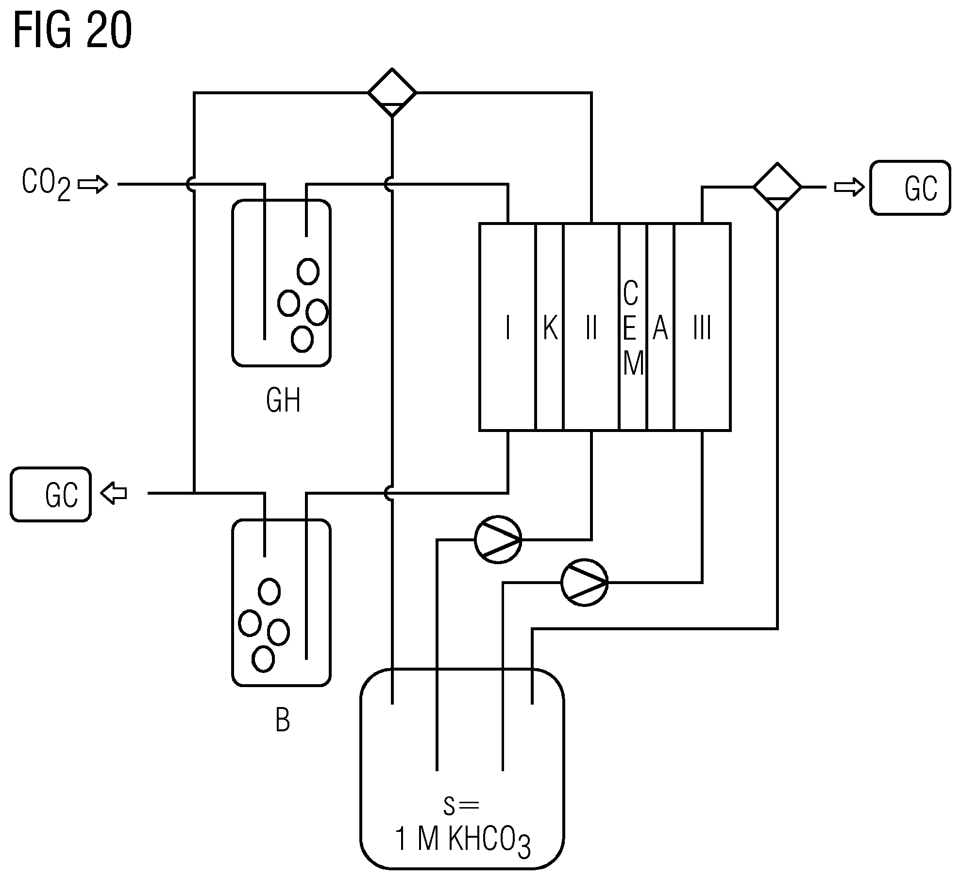
D00013


XML
uspto.report is an independent third-party trademark research tool that is not affiliated, endorsed, or sponsored by the United States Patent and Trademark Office (USPTO) or any other governmental organization. The information provided by uspto.report is based on publicly available data at the time of writing and is intended for informational purposes only.
While we strive to provide accurate and up-to-date information, we do not guarantee the accuracy, completeness, reliability, or suitability of the information displayed on this site. The use of this site is at your own risk. Any reliance you place on such information is therefore strictly at your own risk.
All official trademark data, including owner information, should be verified by visiting the official USPTO website at www.uspto.gov. This site is not intended to replace professional legal advice and should not be used as a substitute for consulting with a legal professional who is knowledgeable about trademark law.