Protective Case For Mobile Electronic Device With Storage Compartment
Hemesath; Timothy
U.S. patent application number 17/103945 was filed with the patent office on 2021-03-18 for protective case for mobile electronic device with storage compartment. This patent application is currently assigned to Incipio, LLC. The applicant listed for this patent is Incipio, LLC. Invention is credited to Timothy Hemesath.
| Application Number | 20210076792 17/103945 |
| Document ID | / |
| Family ID | 1000005240126 |
| Filed Date | 2021-03-18 |

| United States Patent Application | 20210076792 |
| Kind Code | A1 |
| Hemesath; Timothy | March 18, 2021 |
PROTECTIVE CASE FOR MOBILE ELECTRONIC DEVICE WITH STORAGE COMPARTMENT
Abstract
A protective case for a mobile device having a front cover and a storage compartment for storage of personal items such as credit cards, personal identification cards, and/or cash is disclosed. The protective case includes a main body and a detachable panel configured to cover an aperture through the shell of the protective case providing access to the storage compartment via a hinged connection. The shell, panel, and front are secured to flexible layers, which allow the case to be positioned in one or more viewing/operating positions.
| Inventors: | Hemesath; Timothy; (Clovis, CA) | ||||||||||
| Applicant: |
|
||||||||||
|---|---|---|---|---|---|---|---|---|---|---|---|
| Assignee: | Incipio, LLC Irvine CA |
||||||||||
| Family ID: | 1000005240126 | ||||||||||
| Appl. No.: | 17/103945 | ||||||||||
| Filed: | November 24, 2020 |
Related U.S. Patent Documents
| Application Number | Filing Date | Patent Number | ||
|---|---|---|---|---|
| 16787001 | Feb 10, 2020 | |||
| 17103945 | ||||
| 16277681 | Feb 15, 2019 | 10555589 | ||
| 16787001 | ||||
| 15865246 | Jan 8, 2018 | 10206471 | ||
| 16277681 | ||||
| 62442977 | Jan 6, 2017 | |||
| Current U.S. Class: | 1/1 |
| Current CPC Class: | A45C 2011/001 20130101; A45C 11/182 20130101; A45C 2011/002 20130101; A45C 2200/15 20130101; A45C 2011/003 20130101; A45C 11/00 20130101 |
| International Class: | A45C 11/00 20060101 A45C011/00 |
Claims
1. A user-removable protective case for retaining and protecting a mobile electronic device and containing a personal item, the protective case comprising: an inner layer; an outer layer; a shell formed by a main body and a subpanel, wherein at least a portion of the main body and the subpanel are positioned between the inner layer and the outer layer, the subpanel is coupled to the main body through a hinge, and a cavity dimensioned to retain the mobile electronic device is formed by the shell; and a front cover formed by a cover panel that is positioned between the inner layer and the outer layer, wherein the cover panel is coupled to the subpanel of the shell through a flexible spine; wherein a compartment dimensioned to retain a personal item is formed into the inner layer of the shell, and wherein an aperture positioned and dimensioned to enable the personal item to be inserted into and removed from the compartment when the subpanel is hingedly rotated away from the main body.
2. The protective case of claim 1, wherein the hinge coupling the main body to the subpanel of the shell is formed by the inner layer and the outer layer.
3. The protective case of claim 1, wherein the flexible spine coupling the cover panel of the front cover to the subpanel of the shell is armed by the inner layer and the outer layer.
4. The protective case of claim 1, wherein the front cover is dimensioned to cover a front face of the mobile electronic device when the mobile electronic device is retentively received within the shell and the case is in a completely closed position.
5. The protective case of claim 4, wherein a flap securing mechanism is provided to secure the case in the closed position.
6. The protective case of claim 5, wherein the flap securing mechanism comprises one or more magnets.
7. The protective case of claim 4, wherein the inner and outer layers are adhered to each of the body and subpanel when they are oriented in the closed position.
8. The protective case of claim 1, wherein the subpanel is configured to pivot away from the main body so that the shell can be folded to provide additional use configurations.
9. The protective case of claim 8, wherein the main body of the shell is capable of rotating at the hinge away from the flexible spine and over an inner face of the front cover.
10. The protective case of claim 8, wherein a proximate edge of the main body of the shell is capable of being positioned to rest atop an inner face of the front cover in a conveniently angled, landscape viewing position or stand configuration.
11. The protective case of claim 10, wherein the weight of the mobile electronic device retained in the shell maintains the case in the stand configuration.
12. The protective case of claim 1, wherein one or more pockets are formed on the front cover.
13. The protective case of claim 1, wherein the personal item is retrieved from the compartment by removing the mobile electronic device from the cavity to expose the compartment.
14. The protective case of claim 1, wherein the personal item is retrieved from the compartment by rotating the subpanel away from the main body to expose the aperture when the mobile electronic device is retained in the cavity.
15. The protective case of claim 1, wherein the main body and the subpanel of the shell are as manufactured via infection molding using a polycarbonate.
16. The protective case of claim 1, wherein the main body of the shell is formed of a more rigid material than the subpanel of the shell.
17. The protective case of claim 1, wherein the main body and the subpanel of the shell are made from the same material as the cover panel of the front cover.
18. The protective case of claim 1, wherein the main body of the shell includes one or more recessed regions, wherein the recessed regions and inner layer are dimensioned such that the recessed regions receive the inner layer.
19. The protective case of claim 1, wherein the main body of the shell includes one or more recessed regions, wherein the recessed regions and outer layer are dimensioned such that the recessed regions receive the outer layer.
20. The protective case of claim 1, wherein the main body of the shell includes one or more first recessed regions and one or more second recessed regions, wherein the one or more first recessed regions and the outer layer are dimensioned such that the one or more first recessed regions receive the outer layer, and wherein the one or more second recessed regions and the inner layer are dimensioned such that the one or more second recessed regions receive the inner layer.
Description
CROSS-REFERENCE TO RELATED APPLICATIONS
[0001] This application is a continuation of U.S. patent application Ser. No. 16/787,001, filed on Feb. 10, 2020, which is a continuation-in-part of U.S. patent application Ser. No. 16/277,681, filed on Feb. 15, 2019 and issued as U.S. Pat. No. 10,555,589 on Feb. 11, 2020, which is a continuation of U.S. patent application Ser. No. 15/865,246, filed on Jan. 8, 2018 and issued as U.S. Pat. No. 10,206,471 on Feb. 19, 2019, which claims the benefit of and priority to U.S. Provisional Patent Application Ser. No. 62/442,977, filed on Jan. 6, 2017, the entireties of which are hereby incorporated herein by reference.
BACKGROUND
Field of the Invention
[0002] The present disclosure relates to user removable protective cases and enclosures for mobile electronic devices and, more particularly, to such cases that have a storage compartment.
Description of the Related Art
[0003] Mobile electronic devices, such as smartphones, tablets, laptops, and the like are known to sustain damage from impact and from contamination as a result of the ingress of water or other fluids. Such damage may result, for example, in a cracked screen, scratches on a finished surface, lost or damaged buttons or controls, cracked or bent external both components, and/or failed or malfunctioning electrical components. Protective cases can protect mobile electronic devices from such damage and other types of damage.
[0004] In addition, as the number of features provided by mobile electronic devices has increased, the number of desirable viewing and operating positions for such mobile electronic devices has also increased. Further, users often prefer to store items such as personal identification or credit cards with their mobile electronic devices.
[0005] Accordingly, there remains a need for an improved mobile electronic device case with a storage compartment that is also capable of providing multiple viewing and operating positions for the mobile electronic device.
SUMMARY
[0006] A protective case that is configured to receive, retain, and protect a mobile device is disclosed herein. Such mobile devices typically include a front face and a back face that define the height of the mobile device, a perimeter defined by a top, bottom, right, and left sides residing between the front and back faces, and corners defined at the intersecting regions of the faces and sides. The case may be for a mobile electronic device that is in the form of a mobile phone, a tablet, an MP3 audio player, a multimedia viewer, a laptop, an e-reader, a gaming device, a health tracker, a connected/IoT device, a personal AI assistant device, or another portable handheld electronic device and may have one or more touchscreens and one or more inputs on its front face, back face, and/or its sides.
[0007] The protective case includes three primary components: a shell, a front cover, and a flexible spine. The shell is dimensioned and configured to securely and removably retain the electronic device and includes a compartment for storing a personal item, where the compartment is accessible beneath a hingedly attached subpanel. The front cover is dimensioned to approximate the front face of the electronic device with an additional curved perimeter region to partially curve around the front face of the mobile device to protect the entire mobile device and its corners. The flexible spine secures the front cover to the shell.
[0008] The shell may include a main body and a detachable subpanel, each of which have an inner surface and an outer surface. The main body defines a cavity for containing the mobile electronic device and the compartment for containing a credit card or personal item. The shell includes an aperture through its hack panel that is positioned to partially expose the compartment and is dimensioned to receive the subpanel. The subpanel is positioned to correspond to the aperture formed in the main body and hinged along a first side to the main body and secured on a second side to the flexible spine. One or more attachment protrusions are provided and configured to mechanically secure the subpanel into the aperture of the main body at or near the second side or location to thereby secure the subpanel to the main body of the shell.
[0009] When the subpanel is attached or otherwise secured at the second side, the subpanel and main body maintain a fixed relative position and orientation to one another. The subpanel is dimensioned such that when it is positioned within the aperture of the main body, there is a slot or gap between opposing edges of the subpanel and the adjacent edge of the aperture. The shell also includes an indentation or a lip at one or more regions around the aperture that is dimensioned to engage with the corresponding edge or lip regions of the subpanel to prevent the subpanel from swinging into the mobile device compartment formed by the shell and its main body.
[0010] The cover may include a front cover panel configured or dimensioned to include a perimeter that is coextensive in dimension with the front face of the mobile device so that it may cover the entirety of the touch screen of the mobile device. The flexible spine connects the front cover panel to the shell via the subpanel. The flexible spine component may include two opposing flexible inner and outer layers that are overlaid and secured on respective opposing inner and outer sides of the front cover panel, the subpanel, and some or all of the shell, including the panel. The opposing overlaid layers may form the hinge that connects the subpanel to the main body of the shell portion and attaches the shell component to the front cover component. The flexible spine is adapted to allow relative movement between the shell and cover components and to allow the cover to open and close over the shell when the case is opened and closed. The front cover includes a flap or tab at an end opposite the flexible spine, where the flap or tab includes an additional rigid flap insert and a flap-securing fastener such as a snap, magnet, latch, hook, or similar. The flap-securing fastener engages a corresponding fastener receiver such as a magnet, a snap, a latch, a hook, or similar on or in the back of the shell or the side of the shell opposite the flexible spine to secure the front cover in place relative to the shell. The inner face of the cover may include one or more slots or openings in the inner layer so as to create a wallet for credit cards and the like.
[0011] The front cover panel, the subpanel, the panel, and/or the flap insert may be formed from polycarbonate (PC), thermoplastic urethane (TPU), a thermoplastic elastomer (TPE), an acrylonitrile butadiene styrene (ABS), nylon, silicone rubber, a combination thereof, or any other rigid or semi-rigid polymer. The front cover panel, the subpanel, and the panel may alternatively be formed of wood, stone, metal, or other natural materials. The opposing flexible inner and outer layer of the flexible spine may be made of synthetic materials or organic textiles or fabrics. The flexible inner and outer layer may be made of the same material or may be made of different materials that provide different desirable benefits for the internal and external portions. For example, the internal layer may prioritize friction to minimize credit card or electronic device slipping and softness to avoid scratches, while the outer layer may prioritize durability, water-resistance, or fashionable textures. The inner layer may be configured to cover some, all, or most of the mobile device cavity defined by the shell portion including the inner faces of the main body and subpanels of the shell. The inner layer may also cover the inner face of the front cover panel, which may be configured to be in contact with the front face of the mobile device when the case is in the closed position. Additional layers may also be co-molded or otherwise incorporated into the protective case.
[0012] In use, in a closed configuration, the subpanel is positioned and secured within the aperture of the shell and the front cover forms a cover for the shell, partially enclosing the mobile electronic device and a credit card secured behind the mobile electronic device beneath the subpanel. In a flat position, the subpanel remains in position and secured within the aperture of the shell, but the flexible spine lays flat, allowing the front cover to lay flat next to the shell (like an open book). In the flat configuration, the credit card remains secured behind the mobile electronic device and beneath the subpanel. In a stand configuration, the subpanel is disengaged and rotated away from the aperture and the flexible spine is flexed to position an edge of the shell to rest on the front cover, supporting the mobile electronic device in a landscape view. In the stand configuration, a credit card behind the mobile electronic device remains secured between the mobile electronic device and the panel; however, a portion of the credit card may be accessible through the aperture, as the subpanel is rotated away. In the open configuration, the subpanel is disengaged and rotated away from the aperture, revealing a credit card contained in the compartment behind the mobile electronic device, enabling a user to remove the credit card from the compartment through the aperture.
[0013] Instead of adding weight to the case to retain the case in the selected viewing position, the case is retained in the selected position as a result of the three resulting from the weight of the mobile device contained within the case. Thus, the case may be manufactured or configured with lightweight materials and so that it would not hold an angled viewing position by itself without the mobile device contained therein. Rather, the case may preferably be configured to be biased to a closed position where the subpanel and main body are generally parallel to one another and not rotated relative to one another. This may be achieved by securing the layers over the main body and subpanel of the shell while the subpanel is closed and thus the overlaid layers will exhibit a natural tension when the subpanel is opened and therefore bias the subpanel into the closed position.
[0014] Each of the foregoing and various aspects, together with those set forth in the claims and summarized above or otherwise disclosed herein, including the figures, may be combined without limitation to form claims for a device, apparatus, system, method of manufacture, and/or method of use.
BRIEF DESCRIPTION OF THE DRAWINGS
[0015] The figures provided herewith are intended to illustrate but not to limit the invention. Like reference characters in the figures denote corresponding features consistently throughout similar embodiments.
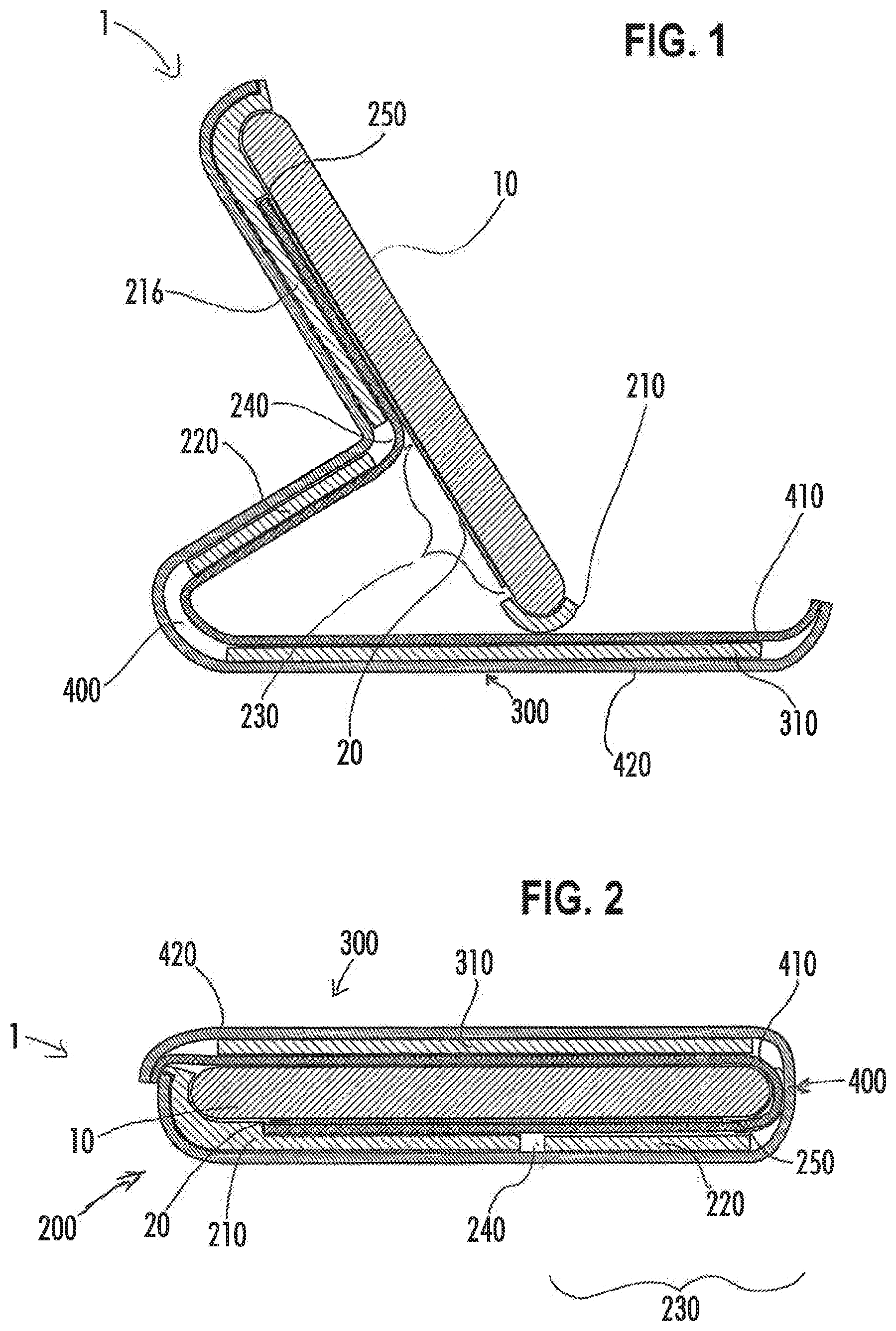
[0016] FIG. 1 is a cross-sectional view of a first embodiment of the protective case containing a mobile device and a credit card in a stand configuration.
[0017] FIG. 2 is a cross-sectional view of the embodiment of the protective case shown in FIG. 1 containing a mobile device and a credit card in a closed configuration.
DETAILED DESCRIPTION OF THE ILLUSTRATED EMBODIMENTS
[0018] A protective case that is configured to receive, retain, and protect a mobile device is disclosed herein. Such mobile devices typically include a front face and a back face that define the height of the mobile device, a perimeter defined by a top, bottom, right, and left sides residing between the front and back faces, and corners defined at the intersecting regions of the faces and sides. The case may be for a mobile electronic device that is in the form of a mobile phone, a tablet, an MP3 audio player, a multimedia viewer, a laptop, an e-reader, a gaming device, a health tracker, a connected/IoT device, a personal AI assistant device, or another portable handheld electronic device and may have one or more touchscreens and one or more inputs on its front face, back face, and/or its sides.
[0019] The disclosed protective case is capable of providing user storage for personal items and different user viewing/operating positions while minimizing bulkiness and weight without sacrificing protection.
[0020] The protective case includes three primary components: a shell, a front cover, and a flexible spine. The shell is dimensioned and configured to securely and removably retain the electronic device and includes a compartment for storing a personal item, where the compartment is accessible beneath a hingedly attached subpanel. The front cover is dimensioned to approximate the front face of the electronic device with an additional curved perimeter region to partially curve around the front face of the mobile device to protect the entire mobile device and its corners. The flexible spine secures the front cover to the shell.
[0021] The shell may include a main body and a detachable subpanel, each of which have an inner surface and an outer surface. The main body defines a cavity for containing the mobile electronic device and the compartment for containing a credit card or personal item. The shell includes an aperture through its back panel that is positioned to partially expose the compartment and is dimensioned to receive the subpanel. The subpanel is positioned to correspond to the aperture teamed in the main body and hinged along a first side to the main body and secured on a second side to the flexible spine. One or more attachment protrusions are provided and configured to mechanically secure the subpanel into the aperture of the main body at or near the second side or location to thereby secure the subpanel to the main body of the shell.
[0022] When the subpanel is attached or otherwise secured at the second side, the subpanel and main body maintain a fixed relative position and orientation to one another. The subpanel is dimensioned such that when it is positioned within the aperture of the main body, there is a slot or gap between opposing edges of the subpanel and the adjacent edge of the aperture. The shell also includes an indentation or a lip at one or more regions around the aperture that is dimensioned to engage with the corresponding edge or lip regions of the subpanel to prevent the subpanel from swinging into the mobile device compartment formed by the shell and its main body.
[0023] The cover may include a front cover panel configured or dimensioned to include a perimeter that is coextensive in dimension with the front face of the mobile device so that it may cover the entirety of the touch screen of the mobile device. The flexible spine connects the front cover panel to the, shell via the subpanel. The flexible spine component may include two opposing flexible inner and outer layers that are overlaid and secured on respective opposing inner and outer sides of the from cover panel, the subpanel and some or all of the shell, including the panel. The opposing overlaid layers may firm the hinge that connects the subpanel to the main body of the shell portion and attaches the shell component to the front cover component. The flexible spine is adapted to allow relative movement between the shell and cover components and to allow the cover to open and close over the shell when the case is opened and closed. The front cover includes a flap or tab at an end opposite the flexible spine, where the flap or tab includes an additional rigid flap insert and a flap-securing fastener such as a snap, magnet, latch, hook, or similar. The flap-securing fastener engages a corresponding fastener receiver such as a magnet, a snap, a latch, a hook, or similar on or in the back of the shell or the side of the shell opposite the flexible spine to secure the front cover in place relative to the shell. The inner face of the cover may include one or more slots or openings in the inner layer so as to create a wallet for credit cards and the like.
[0024] The front cover panel, the subpanel, the panel, and/or the flap insert may be formed from polycarbonate (PC), thermoplastic urethane (TPU), a thermoplastic elastomer (TPE), an acrylonitrile butadiene styrene (ABS), nylon, silicone rubber, a combination thereof, or any other rigid or semi-rigid polymer. The front cover panel, the subpanel, and the panel may alternatively be formed of wood, stone, metal, or other natural materials. The opposing flexible inner and outer layer of the flexible spine may be made of synthetic materials or organic textiles or fabrics. The flexible inner and outer layer may be made of the same material or may be made of different materials that provide different desirable benefits for the internal and external portions. For example, the internal layer may prioritize friction to minimize credit card or electronic device slipping and softness to avoid scratches, while the outer layer may prioritize durability, water-resistance, or fashionable textures. The inner layer may be configured to cover some, all, or most of the mobile device cavity defined by the shell portion including the inner faces of the main body and subpanels of the shell. The inner layer may also cover the inner face of the front cover panel, which may be configured to be in contact with the front face of the mobile device when the case is in the closed position. Additional layers may also be co-molded or otherwise incorporated into the protective case.
[0025] In use, in a closed configuration, the subpanel is positioned and secured within the aperture of the shell and the front cover forms a cover for the shell, partially enclosing the mobile electronic device and a credit card secured behind the mobile electronic device beneath the subpanel. In a flat position, the subpanel remains in position and secured within the aperture of the shell, but the flexible spine lays flat, allowing the front cover to lay fiat next to the shell (like an open book), In the flat configuration, the credit card remains secured behind the mobile electronic device and beneath the subpanel. In a stand configuration, the subpanel is disengaged and rotated away from the aperture and the flexible spine is flexed to position an edge of the shell to rest on the front cover, supporting the mobile electronic device in a landscape view. In the stand, configuration, a credit card behind the mobile electronic device remains secured between the mobile electronic device and the panel; however, a portion of the credit card may be accessible through the aperture, as the subpanel is rotated away. In the open configuration, the subpanel is disengaged and rotated away from the aperture, revealing a credit card contained in the compartment behind the mobile electronic device, enabling a user to remove the credit card from the compartment through the aperture.
[0026] Instead of adding weight to the case to retain the case in the selected viewing position, the case is retained in the selected position as a result of the three resulting from the weight of the mobile device contained within the case. Thus, the case may be manufactured or configured with lightweight materials and so that it would not hold an angled viewing position by itself without the mobile device contained therein. Rather, the case may preferably be configured to be biased to a closed position where the subpanel and main body are generally parallel to one another and not rotated relative to one another. This may be achieved by securing the layers over the main body and subpanel of the shell while the subpanel is closed and thus the overlaid layers will exhibit a natural tension when the subpanel is opened and therefore bias the subpanel into the closed position.
[0027] As shown in FIGS. 1-2, the protective case 1 is generally configured to receive and protect a mobile device 10. The case 1 generally includes a shell 200, where the shell 200 includes a main body 210 and a subpanel 220, and a front cover 300 that includes a from cover panel 310 that is attached to the shell 200 via a flexible spine 400. A flexible inner layer 410 and outer layer 420 overlay and are secured to opposing sides of the main body 210, the subpanel 220, front cover panel 310, and a flap insert 321, connecting the components as a single continuous case 1 and enabling relative motion between the components. The flexible inner layer 410 and flexible outer layer 420 are secured together between other components, forming the hinge 240 between the main body 210 and the subpanel 220, forming the flexible spine 400 between the subpanel 220 and the front cover 300, and allowing the flap or tab 320 to move relative to the front cover 300.
[0028] The protective case 1 may be for a mobile electronic device 10 that is in the form of a tablet, a smartphone or mobile phone, an MP3 audio player, a gaming device, or another portable handheld electronic device. Such mobile devices 10 typically include a front face and a back face, where the difference between the two faces defines the height or thickness of the mobile device 10, a perimeter defined by top, bottom, right, and left sides residing between the front and back faces, and corners defined at the intersecting regions of the sides. The entirely, most, or a portion of the front face of the mobile device 10 may be comprised of a touch screen, possibly including one or more buttons and/or a biometric scanner. Screens may be provided on other sides as well, including the back face. The device 10 may have one or more buttons, controls, user interfaces, and/or ports included along its perimeter walls and a camera, flash, and speaker or microphone port on its back face.
[0029] The shell component 200 is generally defined by a front (internal cavity) surface and an opposing rear surface, left and right sides, and top and bottom ends. The front side or face of the shell 200 defines a cavity 255 that is configured to receive and retain the portable electronic device as well as a compartment 250 that is configured and dimensioned to receive and retain a personal item 20 (e.g., an identification card, credit card, debit card, medical insurance card, money, or other item), while allowing a user to access the touchscreen on the front face of the electronic device 10 and to control interfaces on the device 10. The shell component 200 may be in the form of contoured molded polymer sub-portions including a main body 210 and a separate subpanel 220 corresponding to an aperture in the main body.
[0030] The main body 210 may also include additional apertures including a camera lens aperture 226 and a speaker and/or microphone aperture 228. Apertures may also be included in the subpanel 240, for example if the subpanel is configured to cover features on the mobile device. Perimeter regions in the shell 200 that reside between one or more of the corners may be removed. Mid-section regions of the shell 200 may be removed to allow for user utilization of device features that are located on the side walls and/or back face of the mobile device 10.
[0031] The main body 210 and subpanel 220 each have inner surfaces and outer surfaces respectively. The inner layer 410 and outer layer 420 sandwich the main body 219 and subpanel 220, with the inner layer 410 secured to the inner surfaces of the main body and subpanel and the outer layer 420 secured to the outer layer of the main body and subpanel. The inner 410 and outer layers 420 may be attached or adhered to one another and the interposed components (e.g., the shell panels and cover panel) via any suitable method including mechanical stitching, chemical adhesion, glue, heat sealing, or a combination thereof. Additional layers may be secured between either of the layers 410 and 429 and any of the interposed or secured elements 210, 220, 390, and 321 or even between the layers 410 and 420 at the hinge 240 or flexible spine 400.
[0032] The aperture 230 through the back surface of the shell is positioned to partially expose the personal item compartment 250 and is dimensioned to receive the subpanel. The main body 214) and the subpanel 220 include overlapping lips or edges configured to provide a mechanical stop and keep the subpanel 220 from rotating into the cavity 255 and compartment 250 through the aperture. One or more attachment protrusions 260 are provided and configured to mechanically secure the subpanel 220 into the aperture 230 of the main body 219 at or near the second side or location to thereby secure the subpanel 220 to the main body 210 of the shell 200. The combination of the hinged connection 240 on one side and the mechanical detents or attachment protrusions 260 on the other side of the aperture 230 allow the subpanel 220 to rotatably lock and unlock into and out of the main body 210.
[0033] The subpanel 220 is positioned to correspond to the aperture formed in the main body 219 and a hinge 240, formed by the inner layer 410 and outer layer secured together between the main body 410 and the subpanel 220, connects the subpanel 220 along a first side to the main body 210 and a flexible spine 400, formed by the inner layer 410 and outer layer secured together between the subpanel 229 and the front cover panel 310, secures the subpanel 220 to the front cover panel 310 on a second side. In other embodiments, only an inner layer 410 may be used without an outer layer 420 or an outer layer 420 may be used without an inner layer 410 to connect the components of the case 1. Alternatively, the construction of the elements may be reversed from that as described, to include a single flexible layer sandwiched between the rigid elements, but otherwise acting as described herein. Instead of or in addition to relying on the hinge 240 and flexible spine 400 formed by the joined inner layer 410 and outer layer 420, the subpanel 220 may be secured to the main body 210 by other rotatable connections or conventional hinge connections, including one or more of a living hinge, a pin and socket, or in some cases, the subpanel 220 may be formed of a flexible material.
[0034] In the illustrated embodiment, the front face of the main body 210 of the shell 200 defines a cavity that is configured to snap onto and retain an electronic device 10 (not shown) securely within the cavity 255 and a credit card compartment 259 defined by the contoured walls of the main panel 220. Notably, the shell 200 is configured such that the main body 210 alone, without the subpanel 220, defines a retention cavity 255 that covers at least partially all or some of the four sides and at least a portion of the back face of the mobile device 10 and is adapted to snap onto or over the mobile device 10 and securely retain the electronic device 10 that it is configured to receive.
[0035] The personal item 20 is positioned in the compartment 250 behind the cavity 255, so that an electronic device 10 retained in the cavity 255 presses the personal item 20 against the front wall of the shell 200. The personal item 20 may be retrieved from the compartment 250 by either removing the mobile electronic device 10 from the cavity 255 to expose the compartment 250, or by rotating the subpanel 220 away from the main body 210 to expose the aperture 239, allowing a user to retrieve the personal item 20 from the compartment 250 through the aperture 230, even when an electronic device 10 is retained in the cavity 255. The subpanel 220. therefore, is not required for retention of the mobile electronic device 10 in the cavity 255 of the shell 200, but is required to secure a personal item 20 in the compartment 250 behind the cavity 255.
[0036] The front cover component 300 is configured to cover the front face of the mobile device 10 when the case 1 is completely closed. The front cover 300 is defined by a front (internal) surface and an opposing rear surface, left, right, top and bottom edges or sides that correspond to the front, hack, left, right, top, and bottom sides of the shell 200 when the case 1 is in the completely closed position and the front cover 300 is on top of the shell 200. The front cover component 300 includes a front cover panel 310, overlaid on opposing sides with the inner layer 410 and the outer layer 420. One or more slots or openings 330 may be formed into the inner layer 410 over the front cover panel 310 to form a wallet or credit card holder. Additionally, loops or pockets 340 may be formed on the front or rear surfaces of the front cover 300.
[0037] The components of the shell 209 may be made of any suitable material. For example, the shell components 210 and 220 may be manufactured via injection molding using a suitable polymer such as polycarbonate and/or fiber (e.g., carbon or Kevlar) reinforced plastic or polymers. In other embodiments, case 1 may be constructed of natural materials including metal, bone, wood, or stone. The main body 210 of the shell 200 may be formed of the same or different material from the subpanel 220 of the shell 200. For example, the main body 210 may be formed of a more rigid material than the subpanel or vice versa. Similarly the front cover panel and flap insert 321 may be made of the same or different materials from the components of the shell 200. In some embodiments, securing fasteners such as flap 325 may require additional or specific materials, such as a magnetic flap 325 securing to a magnetic shell 270. In some embodiments, both the flap 325 and shell 270 are magnetized, while in other embodiments only one of the flap 325 and shell 270 is magnetized while the other is a ferromagnetic material such as iron.
[0038] In order to bias the subpanel to the closed position, the layers 410 and 420 may be adhered to each of the shell body 210 and subpanel 220 when they are oriented in the dosed position. The inner layer 410 and outer layer 420 will therefore be biased (perhaps only slightly) against the subpanel 220 opening or hinging away from the main body 210 of the shell 200.
[0039] The inner surfaces of the main body and subpanel of the shell 290 include recessed regions or attachment areas dimensioned to receive correspondingly dimensioned inner layer 410 regions. Similarly, the outer surfaces of the main body and subpanel of the shell 200 include recessed regions dimensioned to receive correspondingly dimensioned outer layer 420 regions, incorporating recessed regions in the inner and outer faces mitigates peeling of the flexible inner 410 and outer 420 layers. Due to the recessed regions, the outer surfaces of the inner 410 and outer 420 layers are flush with or lower than the outer surfaces of the adjacent surrounding more rigid elements of the case 1.
[0040] In a stand configuration, the subpanel 220 may be disengaged by the user from the attachment protrusions 260 of the main body 210, allowing the main body 210 to pivot at the hinge 240 (relative to the subpanel 220), folding the case 1 over itself to form a different viewing or operating position as illustrated in FIGS. 1-2. Additionally, with the subpanel 220 pivoted away from the main body 210, the main body 210 can rotate at the hinge 240 away from the flexible spine 400 and over the inner face of the front cover 300. The proximate edge of the main body 210 of the shell 200 (i.e., the left side or edge) can be positioned to rest atop the inner face of the front cover 300 in a conveniently-angled landscape viewing position or stand configuration. The weight of the mobile electronic device 10 retained in the shell 200 maintains the case 1 in the desired stand configuration. By using the weight of the mobile device 10 to provide the added weight or force necessary to bias the case 1 into a desired viewing or operating position, the case 1 can be manufactured using lighter materials.
[0041] A method of manufacturing the disclosed case is also disclosed herein. A shell 200, including a main body 210 and subpanel 220, and a front cover 300 as described above may be molded or formed and then overlaid between flexible inner and outer layers 410 and 420. A hinge 240, connecting the subpanel 220 over an aperture 230 in the main body 210 of the shell 200, is provided between the subpanel 220 and the main body 210 along a first side or edge. The hinge 240 may be formed by the overlaid inner and/or outer layers 410 and 420. The inner 410 and/or outer 420 layers may be overlaid when the subpanel 220 and the main body 210 are in the closed position to bias the case into the closed position.
[0042] The previous description of the disclosed embodiments is provided to enable any person skilled in the art to make or use the invention disclosed herein. Although the various inventive aspects are disclosed in the context of certain illustrated embodiments, implementations, and examples, it should be understood by those skilled in the art that the invention extends beyond the specifically disclosed embodiments to other alternative embodiments and/or uses of the invention and obvious modifications and equivalents thereof. In addition, while a number of variations of various inventive aspects have been shown and described in detail, other modifications that are within their scope will be readily apparent to those skilled in the art based upon reviewing this disclosure. It should be also understood that the scope of this disclosure includes the various combinations or sub-combinations of the specific features and aspects of the embodiments disclosed herein, such that the various features, modes of implementation, and aspects of the disclosed subject matter may be combined with or substituted for one another. The generic principles defined herein may be applied to other embodiments without departing from the spirit or scope of the disclosure. Thus, the present disclosure is not intended to be limited to the embodiments shown herein but is to be accorded the widest scope consistent with the principles and novel features disclosed herein.
[0043] Similarly, the disclosure is not to be interpreted as reflecting an intent that any claim set forth below requires more features than are expressly recited in that claim. Rather, as the following claims reflect, inventive aspects may reside in a combination of fewer than all features of any single foregoing disclosed embodiment.
[0044] Each of the foregoing and various aspects, together with those set forth in the claims and summarized above or otherwise disclosed herein, including the figures, may be combined without limitation to form claims for a device, apparatus, system, method of manufacture, and/or method of use.
[0045] All references cited herein are hereby expressly incorporated by reference.
* * * * *
D00000
D00001
XML
uspto.report is an independent third-party trademark research tool that is not affiliated, endorsed, or sponsored by the United States Patent and Trademark Office (USPTO) or any other governmental organization. The information provided by uspto.report is based on publicly available data at the time of writing and is intended for informational purposes only.
While we strive to provide accurate and up-to-date information, we do not guarantee the accuracy, completeness, reliability, or suitability of the information displayed on this site. The use of this site is at your own risk. Any reliance you place on such information is therefore strictly at your own risk.
All official trademark data, including owner information, should be verified by visiting the official USPTO website at www.uspto.gov. This site is not intended to replace professional legal advice and should not be used as a substitute for consulting with a legal professional who is knowledgeable about trademark law.