Virtual Voltage Injection-based Speed Sensor-less Driving Control Method For Induction Motor
SUN; Wei ; et al.
U.S. patent application number 16/772160 was filed with the patent office on 2021-03-11 for virtual voltage injection-based speed sensor-less driving control method for induction motor. This patent application is currently assigned to HUAZHONG UNIVERSITY OF SCIENCE AND TECHNOLOGY. The applicant listed for this patent is HARBIN INSTITUTE OF TECHNOLOGY, HUAZHONG UNIVERSITY OF SCIENCE AND TECHNOLOGY. Invention is credited to Wei SUN, Dianguo XU.
| Application Number | 20210075354 16/772160 |
| Document ID | / |
| Family ID | 1000005252262 |
| Filed Date | 2021-03-11 |


View All Diagrams
| United States Patent Application | 20210075354 |
| Kind Code | A1 |
| SUN; Wei ; et al. | March 11, 2021 |
VIRTUAL VOLTAGE INJECTION-BASED SPEED SENSOR-LESS DRIVING CONTROL METHOD FOR INDUCTION MOTOR
Abstract
A virtual voltage injection-based speed sensor-less driving control method for an induction motor is provided. First, a virtual voltage signal is injected into a motor flux linkage and rotating speed observer so that there is a difference between an input of the motor flux linkage and rotating speed observer and a command input of the motor. Then, based on any type of the motor flux linkage and rotating speed observer, a motor flux linkage rotation angle and a motor rotor speed are estimated, and the induction motor is driven to run normally with a certain control strategy (such as vector control). Then, based on a signal designed according to this method and injected only into the motor flux linkage and rotating speed observer, the induction motor driven by a speed sensor-less control system for the induction motor may be ensured to output 150% of a rated torque when running at a motor low synchronous rotating speed and a motor zero synchronous rotating speed, and the stability thereof may be kept for a long time.
| Inventors: | SUN; Wei; (Hubei, CN) ; XU; Dianguo; (Hubei, CN) | ||||||||||
| Applicant: |
|
||||||||||
|---|---|---|---|---|---|---|---|---|---|---|---|
| Assignee: | HUAZHONG UNIVERSITY OF SCIENCE AND
TECHNOLOGY Hubei CN HARBIN INSTITUTE OF TECHNOLOGY Heilongjiang CN |
||||||||||
| Family ID: | 1000005252262 | ||||||||||
| Appl. No.: | 16/772160 | ||||||||||
| Filed: | May 25, 2018 | ||||||||||
| PCT Filed: | May 25, 2018 | ||||||||||
| PCT NO: | PCT/CN2018/088315 | ||||||||||
| 371 Date: | June 12, 2020 |
| Current U.S. Class: | 1/1 |
| Current CPC Class: | H02P 21/04 20130101; H02P 27/12 20130101; H02P 21/0021 20130101; H02P 21/28 20160201; H02P 21/18 20160201; H02P 6/183 20130101; H02P 21/13 20130101 |
| International Class: | H02P 21/13 20060101 H02P021/13; H02P 21/04 20060101 H02P021/04; H02P 21/18 20060101 H02P021/18; H02P 21/28 20060101 H02P021/28; H02P 27/12 20060101 H02P027/12; H02P 21/00 20060101 H02P021/00; H02P 6/18 20060101 H02P006/18 |
Foreign Application Data
| Date | Code | Application Number |
|---|---|---|
| May 15, 2018 | CN | 201810462918.6 |
Claims
1. A virtual voltage injection-based speed sensor-less driving control method for induction motor, wherein in the method, based on an existing speed sensor-less drive system for induction motor, a virtual voltage injection module is added between stator voltage command input values u.sub.s.alpha. and u.sub.s.beta. and flux linkage observer stator voltage input values u*.sub.s.alpha. and u*.sub.s.beta. of a motor in an .alpha..beta. coordinate system, or a virtual voltage injection module is added between stator voltage command input values u.sub.sd and u.sub.sq and flux linkage observer stator voltage input values u*.sub.sd and u*.sub.sq of the motor in a dq coordinate system, and the method comprises the following steps: S1. calculating k based on a parameter of an induction motor, wherein k is a proportional relationship in the virtual voltage injection module; S2. multiplying the stator voltage command input values u.sub.s.alpha. and u.sub.s.beta. of the motor in the .alpha..beta. coordinate system by the proportional relationship k respectively to obtain the flux linkage observer stator voltage input values u*.sub.s.alpha. and u*.sub.s.beta. in the .alpha..beta. coordinate system; or multiplying the stator voltage command input values u.sub.sd and u.sub.sq of the motor in the dq coordinate system by the proportional relationship k respectively to obtain the flux linkage observer stator voltage input values u and u in the dq coordinate system; the operation is equivalent to injecting u.sub.s.alpha._inj and u.sub.s.beta._inj on the basis of u.sub.s.alpha. and u.sub.s.beta., wherein u s .alpha. _inj = ( k - 1 ) u s .alpha. ##EQU00020## u s .beta. _inj = ( k - 1 ) u s .beta. , ##EQU00020.2## to satisfy u s .alpha. * = u s .alpha. _inj + u s .alpha. = k u s .alpha. ##EQU00021## u s .beta. * = u s .beta. _inj + u s .beta. = k u s .beta. , ##EQU00021.2## in the formula, u.sub.s.alpha._inj is a virtual voltage injection value under an .alpha.-axis, and u.sub.s.beta._inj is a virtual voltage injection value under a .beta.-axis; or the operation is equivalent to injecting u.sub.sd_inj and u.sub.sq_inj on the basis of u.sub.sd and u.sub.sq, wherein u s d _inj = ( k - 1 ) u s d ##EQU00022## u s q _inj = ( k - 1 ) u s q , ##EQU00022.2## to satisfy u s d * = u s d _inj + u s d = k u s d ##EQU00023## u s q * = u s q _inj + u s q = k u s q , ##EQU00023.2## in the formula, u.sub.sd_inj is a virtual voltage injection value under a d-axis, and u.sub.sq_inj is a virtual voltage injection value under a q-axis; S3. constructing a dynamic mathematical model of a flux linkage observer based on u*.sub.s.alpha. and u*.sub.s.beta. or u*.sub.sd and u*.sub.sq; S4. observing an induction motor rotor speed {circumflex over (.omega.)}.sub.r using a rotating speed observer and observing a rotation angle {circumflex over (.theta.)} of a rotor flux linkage using the flux linkage observer based on the dynamic mathematical model of the flux linkage observer; S5. implementing a control of speed sensor-less induction motor rotating speed and torque by using the observed rotor speed {circumflex over (.omega.)}.sub.r for a rotating speed PI adjustment module and the flux linkage observer and using the observed rotor flux linkage rotation angle {circumflex over (.theta.)} for a 2-phase synchronous rotation coordinate/2-phase static coordinate conversion module; wherein the .alpha..beta. coordinate system is a 2-phase static coordinate system and the dq coordinate system is a 2-phase synchronous rotation coordinate system.
2. The driving control method of claim 1, wherein the virtual voltage injection module is implemented by an adder, a multiplier, or a combination thereof.
3. The driving control method of claim 1, wherein a calculation formula of the proportional relationship k in step S1 is as follows: k = p R r L m L r + 1 ##EQU00024## wherein p is a constant greater than zero, and is obtained based on the rated parameters of induction motor; R.sub.r is an induction motor rotor resistance; L.sub.m is an induction motor mutual inductance; and L.sub.r is an induction motor rotor side inductance.
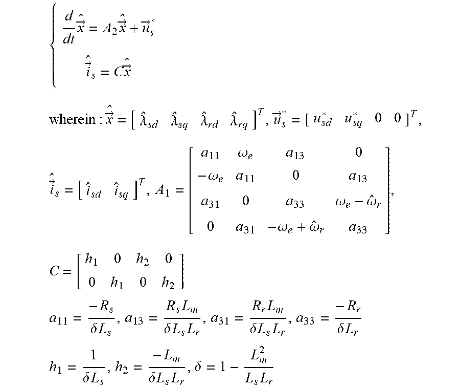
4. The driving control method of claim 1, wherein the dynamic mathematical model of the flux linkage observer constructed based on u*.sub.s.alpha. and u*.sub.s.beta. in step S3 is as follows: { d dt x .fwdarw. ^ = A 1 x .fwdarw. ^ + u .fwdarw. s * i .fwdarw. ^ s = C x .fwdarw. ^ wherein : x .fwdarw. ^ = [ .lamda. ^ s .alpha. .lamda. ^ s .beta. .lamda. ^ r .alpha. .lamda. ^ r .beta. ] T , u .fwdarw. s * = [ u s .alpha. * u s .beta. * 0 0 ] T , i .fwdarw. ^ s = [ i ^ s .alpha. i ^ s .beta. ] T , A 1 = [ a 11 0 a 13 0 0 a 11 0 a 13 a 31 0 a 33 - .omega. ^ r 0 a 31 .omega. ^ r a 33 ] , C = [ h 1 0 h 2 0 0 h 1 0 h 2 ] a 11 = - R s .delta. L s , a 13 = R s L m .delta. L s L r , a 31 = R r L m .delta. L s L r , a 33 = - R r .delta. L r h 1 = 1 .delta. L s , h 2 = - L m .delta. L s L r , .delta. = 1 - L m 2 L s L r ##EQU00025## the dynamic mathematical model of the flux linkage observer constructed based on u*.sub.sd and u*.sub.sq is as follows: { d dt x .fwdarw. ^ = A 2 x .fwdarw. ^ + u .fwdarw. s * i .fwdarw. ^ s = C x .fwdarw. ^ wherein : x .fwdarw. ^ = [ .lamda. ^ sd .lamda. ^ sq .lamda. ^ r d .lamda. ^ rq ] T , u .fwdarw. s * = [ u sd * u sq * 0 0 ] T , i .fwdarw. ^ s = [ i ^ sd i ^ sq ] T , A 1 = [ a 11 .omega. e a 13 0 - .omega. e a 11 0 a 13 a 31 0 a 33 .omega. e - .omega. ^ r 0 a 31 - .omega. e + .omega. ^ r a 33 ] , C = [ h 1 0 h 2 0 0 h 1 0 h 2 ] a 11 = - R s .delta. L s , a 13 = R s L m .delta. L s L r , a 31 = R r L m .delta. L s L r , a 33 = - R r .delta. L r h 1 = 1 .delta. L s , h 2 = - L m .delta. L s L r , .delta. = 1 - L m 2 L s L r ##EQU00026## wherein {circumflex over (.lamda.)}.sub.s.alpha., {circumflex over (.lamda.)}.sub.s.beta., {circumflex over (.lamda.)}.sub.sd, and {circumflex over (.lamda.)}.sub.sq are stator flux linkage observation values under the .alpha.-axis, the .beta.-axis, the d-axis, and the q-axis respectively; {circumflex over (.lamda.)}.sub.r.alpha., {circumflex over (.lamda.)}.sub.r.beta., {circumflex over (.lamda.)}.sub.rd, and {circumflex over (.lamda.)}.sub.rq are rotor flux linkage observation values under the .alpha.-axis, the .beta.-axis, the d-axis, and the q-axis respectively; .sub.s.alpha., .sub.s.beta., .sub.sd, and .sub.sq are stator current observation values under the .alpha.-axis, the .beta.-axis, the d-axis, and the q-axis respectively; Weis asynchronous rotating speed; R.sub.s and R.sub.r are a motor stator resistance and rotor resistance respectively; L.sub.s, L.sub.r, and L.sub.m are a motor stator side inductance, a motor rotor side inductance, and a motor mutual inductance respectively.
5. The driving control method of claim 1, wherein when the dynamic mathematical model of the flux linkage observer is constructed based on u*.sub.s.alpha. and u*.sub.s.beta., a calculation formula of the induction motor rotor speed {circumflex over (.omega.)}.sub.r in step S4 is as follows: {circumflex over (.omega.)}.sub.r=k.sub.p[(i.sub.s.alpha.- .sub.s.alpha.){circumflex over (.lamda.)}.sub.r.beta.-(i.sub.s.beta.- .sub.s.beta.){circumflex over (.lamda.)}.sub.r.alpha.]+k.sub.iS.sub.1 when the dynamic mathematical model of the flux linkage observer is constructed based on u*.sub.sd and u*.sub.sq, the calculation formula of the induction motor rotor speed {circumflex over (.omega.)}.sub.r in step S4 is as follows: {circumflex over (.omega.)}.sub.r=k.sub.p[(i.sub.sd- .sub.sd){circumflex over (.lamda.)}.sub.rq-(i.sub.sq- .sub.sq){circumflex over (.lamda.)}.sub.rd]+k.sub.iS.sub.2 wherein k.sub.p and k.sub.i are a proportional link gain and an integral link gain of the rotating speed observer respectively; i.sub.s.alpha., i.sub.s.beta., i.sub.sd, and i.sub.sq are stator current actual measured values under the .alpha.-axis, the .beta.-axis, the d-axis, and the q-axis respectively; .sub.s.alpha., .sub.s.beta., .sub.sd, and .sub.sq are stator current observation values under the .alpha.-axis, the .beta.-axis, the d-axis, and the q-axis respectively; {circumflex over (.lamda.)}.sub.r.alpha., {circumflex over (.lamda.)}.sub.r.beta., {circumflex over (.lamda.)}.sub.rd, and {circumflex over (.lamda.)}.sub.rq are rotor flux linkage observation values under the .alpha.-axis, the f-axis, the d-axis, and the q-axis respectively; and S.sub.1 and S.sub.2 are time integral values of [(i.sub.s.alpha.- .sub.s.alpha.){circumflex over (.lamda.)}.sub.r.beta.-(i.sub.s.beta.- .sub.s.beta.){circumflex over (.lamda.)}.sub.r.alpha.] and [(i.sub.sd- .sub.sd){circumflex over (.lamda.)}.sub.rq-(i.sub.sq- .sub.sq){circumflex over (.lamda.)}.sub.rd] respectively.
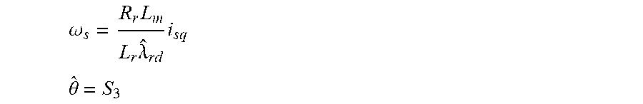
6. The driving control method of claim 1, wherein when the dynamic mathematical model of the flux linkage observer is constructed based on u*.sub.s.alpha. and u*.sub.s.beta., a calculation formula of the rotation angle {circumflex over (.theta.)} in step S4 is as follows: .theta. ^ = arctan .lamda. ^ r .beta. .lamda. ^ r .alpha. ##EQU00027## when the dynamic mathematical model of the flux linkage observer is constructed based on u*.sub.sd and u*.sub.sq, the calculation formula of the rotation angle {circumflex over (.theta.)} in step S4 is as follows: .omega. s = R r L m L r .lamda. ^ r d i sq ##EQU00028## .theta. ^ = S 3 ##EQU00028.2## wherein {circumflex over (.lamda.)}.sub.r.alpha., {circumflex over (.lamda.)}.sub.r.beta., and {circumflex over (.lamda.)}.sub.rd are rotor flux linkage observation values under the .alpha.-axis, the .beta.-axis, and the d-axis respectively; i.sub.sq is a stator current actual measured value under the q-axis, .omega..sub.s is a slip rotating speed, R.sub.r is a motor rotor resistance, L.sub.r and L.sub.m are a motor rotor side inductance and a motor mutual inductance respectively, and S.sub.3 represents a time integral for ({circumflex over (.omega.)}.sub.r+.omega.s).
7. The driving control method of claim 1, wherein step S5 comprises the following steps: S501, performing a rotating speed PI control after taking a difference with a corresponding rotating speed command .omega.*.sub.r using the observed induction motor rotor speed {circumflex over (.omega.)}.sub.r as a feedback value of the rotating speed PI adjustment module; S502, using the observed flux linkage rotation angle {circumflex over (.theta.)} for a coordinate conversion calculation in a 2-phase synchronous rotation coordinate/2-phase static coordinate conversion module; S503, using an output i*.sub.sq of the rotating speed PI adjustment module as a command of a q-axis current PI adjustment module and using an output i*.sub.sd of a flux linkage current command given module as a command of a d-axis current PI adjustment module; inputting induction motor two-phase currents i.sub.U and i.sub.V obtained by sampling via a current sensor to a 3-phase static coordinate/2-phase static coordinate conversion module, and then outputting {right arrow over (i)}.sub.s to the 2-phase synchronous rotation coordinate/2-phase static coordinate conversion module, and lastly obtaining a d-axis current i.sub.sd and a q-axis current i.sub.sq in the 2-phase synchronous rotation coordinate system, and performing a current PI control after using the obtained d-axis current and q-axis current as feedback values of a d-axis current PI regulator and a q-axis current PI regulator respectively and taking a difference with corresponding flux linkage current commands i*.sub.sd and i*.sub.sq; S504, inputting outputs u.sub.sd and u.sub.sq of the d-axis and q-axis current PI adjustment modules to the 2-phase synchronous rotation coordinate/2-phase static coordinate conversion module, which converts a motor input voltage command in the 2-phase synchronous rotation coordinate system to a motor input voltage command {right arrow over (u)}.sub.s in the 2-phase static coordinate system; S505, outputting {right arrow over (u)}.sub.s to a voltage space vector pulse width modulation module to generate a switching signal capable of controlling switching devices S.sub.A, S.sub.B, S.sub.C, thereby achieving an object of controlling induction motor speed and torque.
8. A computer-readable storage medium, wherein a computer program is stored on the computer-readable storage medium, and when the computer program is executed by a processor, the virtual voltage injection-based speed sensor-less driving control method for induction motor of claim 1 is implemented.
9. The driving control method of claim 2, wherein the virtual voltage injection module is implemented by an adder, a multiplier, or a combination thereof.
10. The driving control method of claim 2, wherein a calculation formula of the proportional relationship k in step S1 is as follows: k = p R r L m L r + 1 ##EQU00029## wherein p is a constant greater than zero, and is obtained based on a stability degree of induction motor speed and torque; R.sub.r is an induction motor rotor resistance; L.sub.m is an induction motor mutual inductance; and L.sub.r is an induction motor rotor side inductance.
11. The driving control method of claim 2, wherein the dynamic mathematical model of the flux linkage observer constructed based on u*.sub.s.alpha. and u*.sub.s.beta. in step S3 is as follows: { d dt x .fwdarw. ^ = A 1 x .fwdarw. ^ + u .fwdarw. s * i .fwdarw. ^ s = C x .fwdarw. ^ wherein : x .fwdarw. ^ = [ .lamda. ^ s .alpha. .lamda. ^ s .beta. .lamda. ^ r .alpha. .lamda. ^ r .beta. ] T , u .fwdarw. s * = [ u s .alpha. * u s .beta. * 0 0 ] T , i .fwdarw. ^ s = [ i ^ s .alpha. i ^ s .beta. ] T , A 1 = [ a 11 0 a 13 0 0 a 11 0 a 13 a 31 0 a 33 - .omega. ^ r 0 a 31 .omega. ^ r a 33 ] , C = [ h 1 0 h 2 0 0 h 1 0 h 2 ] a 11 = - R s .delta. L s , a 13 = R s L m .delta. L s L r , a 31 = R r L m .delta. L s L r , a 33 = - R r .delta. L r h 1 = 1 .delta. L s , h 2 = - L m .delta. L s L r , .delta. = 1 - L m 2 L s L r ##EQU00030## the dynamic mathematical model of the flux linkage observer constructed based on u*.sub.sd and u*.sub.sq is as follows: { d dt x .fwdarw. ^ = A 2 x .fwdarw. ^ + u .fwdarw. s * i .fwdarw. ^ s = C x .fwdarw. ^ wherein : x .fwdarw. ^ = [ .lamda. ^ sd .lamda. ^ sq .lamda. ^ r d .lamda. ^ rq ] T , u .fwdarw. s * = [ u sd * u sq * 0 0 ] T , i .fwdarw. ^ s = [ i ^ sd i ^ sq ] T , A 1 = [ a 11 .omega. e a 13 0 - .omega. e a 11 0 a 13 a 31 0 a 33 .omega. e - .omega. ^ r 0 a 31 - .omega. e + .omega. ^ r a 33 ] , C = [ h 1 0 h 2 0 0 h 1 0 h 2 ] a 11 = - R s .delta. L s , a 13 = R s L m .delta. L s L r , a 31 = R r L m .delta. L s L r , a 33 = - R r .delta. L r h 1 = 1 .delta. L s , h 2 = - L m .delta. L s L r , .delta. = 1 - L m 2 L s L r ##EQU00031## wherein {circumflex over (.lamda.)}.sub.s.alpha., {circumflex over (.lamda.)}.sub.s.beta., {circumflex over (.lamda.)}.sub.sd, and {circumflex over (.lamda.)}.sub.sq are stator flux linkage observation values under the .alpha.-axis, the .beta.-axis, the d-axis, and the q-axis respectively; {circumflex over (.lamda.)}.sub.r.alpha., {circumflex over (.lamda.)}.sub.r.beta., {circumflex over (.lamda.)}.sub.rd, and {circumflex over (.lamda.)}.sub.rq are rotor flux linkage observation values under the .alpha.-axis, the .beta.-axis, the d-axis, and the q-axis respectively; .sub.s.alpha., .sub.s.beta., .sub.sd, and .sub.sq are stator current observation values under the .alpha.-axis, the .beta.-axis, the d-axis, and the q-axis respectively; .omega..sub.e is a synchronous rotating speed; R.sub.s and R.sub.r are a motor stator resistance and rotor resistance respectively; L.sub.s, L.sub.r, and L.sub.m are a motor stator side inductance, a motor rotor side inductance, and a motor mutual inductance respectively.
12. The driving control method of claim 2, wherein when the dynamic mathematical model of the flux linkage observer is constructed based on u*.sub.s.alpha. and u*.sub.s.beta., a calculation formula of the induction motor rotor speed {circumflex over (.omega.)}.sub.r in step S4 is as follows: {circumflex over (.omega.)}.sub.r=k.sub.p[(i.sub.s.alpha.- .sub.s.alpha.){circumflex over (.lamda.)}.sub.r.beta.-(i.sub.s.beta.- .sub.s.beta.){circumflex over (.lamda.)}.sub.r.alpha.]+k.sub.iS.sub.1 when the dynamic mathematical model of the flux linkage observer is constructed based on u*.sub.sd and u*.sub.sq, the calculation formula of the induction motor rotor speed {circumflex over (.omega.)}.sub.r in step S4 is as follows: {circumflex over (.omega.)}.sub.r=k.sub.p[(i.sub.sd- .sub.sd){circumflex over (.lamda.)}.sub.rq-(i.sub.sq- .sub.sq){circumflex over (.lamda.)}.sub.rd]+k.sub.iS.sub.2 wherein k.sub.p and k.sub.i are a proportional link gain and an integral link gain of the rotating speed observer respectively; i.sub.s.alpha., i.sub.s.beta., i.sub.sd, and i.sub.sq are stator current actual measured values under the .alpha.-axis, the .beta.-axis, the d-axis, and the q-axis respectively; {right arrow over (i)}.sub.s.alpha., .sub.s.beta., .sub.sd, and .sub.sq are stator current observation values under the .alpha.-axis, the .beta.-axis, the d-axis, and the q-axis respectively; {circumflex over (.lamda.)}.sub.r.alpha., {circumflex over (.lamda.)}.sub.r.beta., {circumflex over (.lamda.)}.sub.rd, and {circumflex over (.lamda.)}.sub.rq are rotor flux linkage observation values under the .alpha.-axis, the .beta.-axis, the d-axis, and the q-axis respectively; and S.sub.1 and S.sub.2 are time integral values of [(i.sub.s.alpha.- .sub.s.alpha.){circumflex over (.lamda.)}.sub.r.beta.-(i.sub.s.beta.- .sub.s.beta.){circumflex over (.lamda.)}.sub.r.alpha.] and [(i.sub.sd- .sub.sd){circumflex over (.lamda.)}.sub.rq-(i.sub.sq- .sub.sq){circumflex over (.lamda.)}.sub.rd] respectively.
13. The driving control method of claim 2, wherein when the dynamic mathematical model of the flux linkage observer is constructed based on u*.sub.s.alpha. and u*.sub.s.beta., a calculation formula of the rotation angle {circumflex over (.theta.)} in step S4 is as follows: .theta. ^ = arctan .lamda. ^ r .beta. .lamda. ^ r .alpha. ##EQU00032## when the dynamic mathematical model of the flux linkage observer is constructed based on u*.sub.sd and u*.sub.sq, the calculation formula of the rotation angle {circumflex over (.theta.)} in step S4 is as follows: .omega. s = R r L m L r .lamda. ^ r d i sq ##EQU00033## .theta. ^ = S 3 ##EQU00033.2## wherein {circumflex over (.lamda.)}.sub.r.alpha., {circumflex over (.lamda.)}.sub.r.beta., and {circumflex over (.lamda.)}.sub.rd are rotor flux linkage observation values under the .alpha.-axis, the .beta.-axis, and the d-axis respectively; i.sub.sq is a stator current actual measured value under the q-axis, .omega..sub.s is a slip rotating speed, R.sub.r is a motor rotor resistance, L.sub.r and L.sub.m are a motor rotor side inductance and a motor mutual inductance respectively, and S.sub.3 represents a time integral for ({circumflex over (.omega.)}.sub.r+.omega..sub.s).
14. The driving control method of claim 2, wherein step S5 comprises the following steps: S501, performing a rotating speed PI control after taking a difference with a corresponding rotating speed command .omega.*.sub.r using the observed induction motor rotor speed {circumflex over (.omega.)}.sub.r as a feedback value of the rotating speed PI adjustment module; S502, using the observed flux linkage rotation angle {circumflex over (.theta.)} for a coordinate conversion calculation in a 2-phase synchronous rotation coordinate/2-phase static coordinate conversion module; S503, using an output i*.sub.sq of the rotating speed PI adjustment module as a command of a q-axis current PI adjustment module and using an output i*.sub.sd of a flux linkage current command given module as a command of a d-axis current PI adjustment module; inputting induction motor two-phase currents i.sub.U and i.sub.V obtained by sampling via a current sensor to a 3-phase static coordinate/2-phase static coordinate conversion module, and then outputting {right arrow over (i)}.sub.s to the 2-phase synchronous rotation coordinate/2-phase static coordinate conversion module, and lastly obtaining a d-axis current i.sub.sd and a q-axis current i.sub.sq in the 2-phase synchronous rotation coordinate system, and performing a current PI control after using the obtained d-axis current and q-axis current as feedback values of a d-axis current PI regulator and a q-axis current PI regulator respectively and taking a difference with corresponding flux linkage current commands i*.sub.sd and i*.sub.sq; S504, inputting outputs u.sub.sd and u.sub.sq of the d-axis and q-axis current PI adjustment modules to the 2-phase synchronous rotation coordinate/2-phase static coordinate conversion module, which converts a motor input voltage command in the 2-phase synchronous rotation coordinate system to a motor input voltage command {right arrow over (u)}.sub.s in the 2-phase static coordinate system; S505, outputting {right arrow over (u)}.sub.s to a voltage space vector pulse width modulation module to generate a switching signal capable of controlling switching devices S.sub.A, S.sub.B, S.sub.C, thereby achieving an object of controlling induction motor speed and torque.
Description
BACKGROUND OF THE INVENTION
Field of the Invention
[0001] The invention belongs to the motor control field, and in particular relates to a virtual voltage injection-based speed sensor-less driving control method for induction motor.
Description of Related Art
[0002] Induction motor (IM) is an AC motor relying on electromagnetic induction to induce rotor current to achieve electromechanical energy conversion, and is substantially an asynchronous motor.
[0003] Motor speed detection devices mostly use speed sensors. The installation of these speed sensors increases the cost of the motor control system. In addition, speed sensors are not suitable for harsh environments such as high humidity, vibration, and electromagnetic noise interference. Therefore, the speed sensorless technology, that is, how to quickly and accurately estimate the rotating speed value of the motor via known speed control system parameters, has become another hot spot in today's research. However, there are also defects in the speed sensor-less driving control system: the motor low-speed operation has weak loading capacity and instability at low-speed power generation.
[0004] In order to ensure that the speed sensor-less drive system for induction motor may run stably for a long time when the motor synchronous rotating speed is zero or the motor rotor speed is zero, many studies have been done in recent years, mainly including low-frequency current signal injection method, high-frequency current/voltage signal injection method, rotor position estimation by detecting zero sequence current harmonics, etc. However, the above methods require the induction motor to have significant magnetic field anisotropy, and depend on motor design, and have issues such as torque fluctuation and noise. No enterprise or research institution may realize the stable operation of the speed sensor-less drive system for induction motor at zero synchronous rotating speed without the signal injection of the motor.
SUMMARY OF THE INVENTION
[0005] In view of the defects of the prior art, an object of the invention is to solve the technical issue of instability of the existing speed sensor-less control system for the induction motor at low synchronous rotating speed and zero synchronous rotating speed.
[0006] To achieve the above object, in a first aspect, the invention provides a virtual voltage injection-based speed sensor-less driving control method for induction motor, wherein in the method, based on an existing speed sensor-less drive system for induction motor, a virtual voltage injection module is added between stator voltage command input values u.sub.s.alpha. and u.sub.s.beta. and flux linkage observer stator voltage input values u*.sub.s.alpha. and u*.sub.s.beta. of a motor in an .alpha..beta. coordinate system, or a virtual voltage injection module is added between stator voltage command input values u.sub.sd and u.sub.sq and flux linkage observer stator voltage input values u*.sub.sd and u*.sub.sq of the motor in a dq coordinate system, and the method includes the following steps:
[0007] S1. k is calculated based on a parameter of an induction motor, wherein k is a proportional relationship in the virtual voltage injection module;
[0008] S2. The stator voltage command input values u.sub.s.alpha. and u.sub.s.beta. of the motor in the .alpha..beta. coordinate system are multiplied by the proportional relationship k respectively to obtain the flux linkage observer stator voltage input values u*.sub.s.alpha. and u*.sub.s.beta. in the .alpha..beta. coordinate system; or the stator voltage command input values u.sub.sd and u.sub.sq of the motor in the dq coordinate system are multiplied by the proportional relationship k respectively to obtain the flux linkage observer stator voltage input values u*.sub.sd and u*.sub.sq in the dq coordinate system;
[0009] the operation is equivalent to injecting u.sub.s.alpha._inj and u.sub.s.beta._inj on the basis of u.sub.s.alpha. and u.sub.s.beta., wherein
u s .alpha. _inj = ( k - 1 ) u s .alpha. ##EQU00001## u s .beta. _inj = ( k - 1 ) u s .beta. , ##EQU00001.2##
to satisfy
u s .alpha. * = u s .alpha. _inj + u s .alpha. = k u s .alpha. ##EQU00002## u s .beta. * = u s .beta. _inj + u s .beta. = k u s .beta. , ##EQU00002.2##
[0010] in the formula, u.sub.s.alpha._inj is a virtual voltage injection value under an .alpha.-axis, and u.sub.s.beta._inj is a virtual voltage injection value under a .beta.-axis;
[0011] or the operation is equivalent to injecting u.sub.sd_inj and u.sub.sq_inj on the basis of u.sub.sd and u.sub.sq, wherein
u s d _inj = ( k - 1 ) u s d ##EQU00003## u s q _inj = ( k - 1 ) u s q , ##EQU00003.2##
to satisfy
u s d * = u s d _inj + u s d = k u s d ##EQU00004## u s q * = u s q _inj + u s q = k u s q , ##EQU00004.2##
[0012] in the formula, u.sub.sd_inj is a virtual voltage injection value under a d-axis, and u.sub.sq_inj is a virtual voltage injection value under a q-axis;
[0013] S3. A dynamic mathematical model of a flux linkage observer is constructed based on u*.sub.s.alpha. and u*.sub.s.beta. or u*.sub.sd and u*.sub.sq;
[0014] S4. An induction motor rotor speed {circumflex over (.omega.)}.sub.r is observed using a rotating speed observer and a rotation angle {circumflex over (.theta.)} of a rotor flux linkage is observed using the flux linkage observer based on the dynamic mathematical model of the flux linkage observer;
[0015] S5. A control of speed sensor-less induction motor rotating speed and torque is implemented by using the observed rotor speed {circumflex over (.omega.)}.sub.r for a rotating speed PI adjustment module and the flux linkage observer and using the observed rotor flux linkage rotation angle {circumflex over (.theta.)} for a 2-phase synchronous rotation coordinate/2-phase static coordinate conversion module;
[0016] wherein the .alpha..beta. coordinate system is a 2-phase static coordinate system and the dq coordinate system is a 2-phase synchronous rotation coordinate system.
[0017] Specifically, the virtual voltage injection module is implemented by an adder, a multiplier, or a combination thereof.
[0018] Specifically, a calculation formula of the proportional relationship k in step S1 is as follows:
k = p R r L m L r + 1 ##EQU00005##
[0019] wherein p is a constant greater than zero, and is obtained based on a stability degree of induction motor speed and torque; R.sub.r is an induction motor rotor resistance; L.sub.m is n induction motor mutual inductance; and L.sub.r is an induction motor rotor side inductance.
[0020] Specifically, the dynamic mathematical model of the flux linkage observer constructed based on u*.sub.s.alpha. and u*.sub.s.beta. in step S3 is as follows:
{ d dt x .fwdarw. ^ = A 1 x .fwdarw. ^ + u .fwdarw. s * i .fwdarw. ^ s = C x .fwdarw. ^ wherein : x .fwdarw. ^ = [ .lamda. ^ s .alpha. .lamda. ^ s .beta. .lamda. ^ r .alpha. .lamda. ^ r .beta. ] T , u .fwdarw. s * = [ u s .alpha. * u s .beta. * 0 0 ] T , i s = [ i s .alpha. i s .beta. ] T A 1 = [ a 11 0 a 13 0 0 a 11 0 a 13 a 31 0 a 33 .omega. ^ r 0 a 31 .omega. ^ r a 33 ] , C = [ h 1 0 h 2 0 0 h 1 0 h 2 ] a 1 1 = - R s .delta. L s , a 1 3 = R s L m .delta. L s L r , a 3 1 = R r L m .delta. L s L r , a 3 3 = - R r .delta. L r h 1 = 1 .delta. L 5 , h 2 = - L m .delta. L s L r , .delta. = 1 - L m 2 L s L r ##EQU00006##
[0021] the dynamic mathematical model of the flux linkage observer constructed based on u*.sub.sd and u*.sub.sq is as follows:
{ d dt x .fwdarw. ^ = A 1 x .fwdarw. ^ + u .fwdarw. s * i .fwdarw. ^ s = C x .fwdarw. ^ wherein : x .fwdarw. ^ = [ .lamda. ^ s .alpha. .lamda. ^ s .beta. .lamda. ^ r .alpha. .lamda. ^ r .beta. ] T , u .fwdarw. s * = [ u s .alpha. * u s .beta. * 0 0 ] T , i s = [ i s .alpha. i s .beta. ] T A 1 = [ a 11 0 a 13 0 0 a 11 0 a 13 a 31 0 a 33 .omega. e - .omega. ^ r 0 a 31 - .omega. e + .omega. ^ r a 33 ] , C = [ h 1 0 h 2 0 0 h 1 0 h 2 ] a 1 1 = - R s .delta. L s , a 1 3 = R s L m .delta. L s L r , a 3 1 = R r L m .delta. L s L r , a 3 3 = - R r .delta. L r h 1 = 1 .delta. L s , h 2 = - L m .delta. L s L r , .delta. = 1 - L m 2 L s L r ##EQU00007##
[0022] wherein {circumflex over (.lamda.)}.sub.s.alpha., {circumflex over (.lamda.)}.sub.s.beta., {circumflex over (.lamda.)}.sub.sd, and {circumflex over (.lamda.)}.sub.sq are stator flux linkage observation values under the .alpha.-axis, the .beta.-axis, the d-axis, and the q-axis respectively; {circumflex over (.lamda.)}.sub.r.alpha., {circumflex over (.lamda.)}.sub.r.beta., {circumflex over (.lamda.)}.sub.rd, and {circumflex over (.lamda.)}.sub.rq are rotor flux linkage observation values under the .alpha.-axis, the f-axis, the d-axis, and the q-axis respectively; .sub.s.alpha., .sub.s.beta., .sub.sd, and .sub.sq are stator current observation values under the .alpha.-axis, the .beta.-axis, the d-axis, and the q-axis respectively; .omega..sub.e is a synchronous rotating speed; R.sub.s and R.sub.r are a motor stator resistance and rotor resistance respectively; and L.sub.s, L.sub.r, and L.sub.m are a motor stator side inductance, a motor rotor side inductance, and a motor mutual inductance respectively.
[0023] Specifically, when the dynamic mathematical model of the flux linkage observer is constructed based on u*.sub.s.alpha. and u*.sub.s.beta., a calculation formula of the induction motor rotor speed {circumflex over (.omega.)}.sub.r in step S4 is as follows:
{circumflex over (.omega.)}.sub.r=k.sub.p[(i.sub.s.alpha.- .sub.s.alpha.){circumflex over (.lamda.)}.sub.r.beta.-(i.sub.s.beta.- .sub.s.beta.){circumflex over (.lamda.)}.sub.r.alpha.]+k.sub.iS.sub.1
[0024] when the dynamic mathematical model of the flux linkage observer is constructed based on u*.sub.sd and u*.sub.sq, the calculation formula of the induction motor rotor speed {circumflex over (.omega.)}.sub.r in step S4 is as follows:
{circumflex over (.omega.)}.sub.r=k.sub.p[(i.sub.sd- .sub.sd){circumflex over (.lamda.)}.sub.rq-(i.sub.sq- .sub.sq){circumflex over (.lamda.)}.sub.rd]+k.sub.iS.sub.2
[0025] wherein k.sub.p and k.sub.i are a proportional link gain and an integral link gain of the rotating speed observer respectively; i.sub.s.alpha., i.sub.s.beta., i.sub.sd, and i.sub.sq are stator current actual measured values under the .alpha.-axis, the .beta.-axis, the d-axis, and the q-axis respectively; .sub.s.alpha., .sub.s.beta., .sub.sd, and .sub.sq are stator current observation values under the .alpha.-axis, the .beta.-axis, the d-axis, and the q-axis respectively; {circumflex over (.lamda.)}.sub.r.alpha., {circumflex over (.lamda.)}.sub.r.beta., {circumflex over (.lamda.)}.sub.rd, and {circumflex over (.lamda.)}.sub.rq are rotor flux linkage observation values under the .alpha.-axis, the f-axis, the d-axis, and the q-axis respectively; and S.sub.1 and S.sub.2 are time integral values of [(i.sub.s.alpha.- .sub.s.alpha.){circumflex over (.lamda.)}.sub.r.beta.-(i.sub.s.beta.- .sub.s.beta.){circumflex over (.lamda.)}.sub.r.alpha.] and [(i.sub.sd- .sub.sd){circumflex over (.lamda.)}.sub.rq-(i.sub.sq- .sub.sq){circumflex over (.lamda.)}.sub.rd] respectively.
[0026] Specifically, when the dynamic mathematical model of the flux linkage observer is constructed based on u*.sub.s.alpha. and u*.sub.s.beta., the calculation formula of the rotation angle {circumflex over (.theta.)} in step S4 is as follows:
.theta. ^ = arctan .LAMBDA. ^ r .beta. .LAMBDA. ^ r .alpha. ##EQU00008##
[0027] when the dynamic mathematical model of the flux linkage observer is constructed based on u*.sub.sd and u*.sub.sq the calculation formula of the rotation angle {circumflex over (.theta.)} in step S4 is as follows:
.omega. s = R r L m L r .lamda. r d i sq ##EQU00009## .theta. ^ = S 3 ##EQU00009.2##
[0028] wherein {circumflex over (.lamda.)}.sub.r.alpha., {circumflex over (.lamda.)}.sub.r.beta., and {circumflex over (.lamda.)}.sub.rd are the rotor flux linkage observation values under the .alpha.-axis, the .beta.-axis, and the d-axis respectively; i.sub.sq is a stator current actual measured value under the q-axis, .omega..sub.s is a slip rotating speed, R.sub.r is a motor rotor resistance, L.sub.r and L.sub.m are a motor rotor side inductance and a motor mutual inductance respectively, and S.sub.3 represents a time integral for ({circumflex over (.omega.)}.sub.r+.omega..sub.s).
[0029] Specifically, step S5 includes the following steps:
[0030] S501, A rotating speed PI control is performed after taking a difference with a corresponding rotating speed command .omega.*.sub.r using the observed induction motor rotor speed {circumflex over (.omega.)}.sub.r as a feedback value of the rotating speed PI adjustment module;
[0031] S502, The observed flux linkage rotation angle {circumflex over (.theta.)} is used for a coordinate conversion calculation in a 2-phase synchronous rotation coordinate/2-phase static coordinate conversion module;
[0032] S503, An output i*.sub.sq of the rotating speed PI adjustment module is used as a command of a q-axis current PI adjustment module and an output i*.sub.sd of a flux linkage current command given module is used as a command of a d-axis current PI adjustment module; induction motor two-phase currents i.sub.U and i.sub.V obtained by sampling via a current sensor is inputted to a 3-phase static coordinate/2-phase static coordinate conversion module, and then {right arrow over (i)}.sub.s is outputted to the 2-phase synchronous rotation coordinate/2-phase static coordinate conversion module, and lastly a d-axis current i.sub.sd and a q-axis current i.sub.sq in the 2-phase synchronous rotation coordinate system are obtained, and a current PI control is performed after using the obtained d-axis current and q-axis current as feedback values of a d-axis current PI regulator and a q-axis current PI regulator respectively and taking a difference with corresponding flux linkage current commands i*.sub.sd and i*.sub.sq;
[0033] S504, Outputs u.sub.sd and u.sub.sq of the d-axis and q-axis current PI adjustment modules are inputted to the 2-phase synchronous rotation coordinate/2-phase static coordinate conversion module, which converts a motor input voltage command in the 2-phase synchronous rotation coordinate system to a motor input voltage command {right arrow over (u)}.sub.s in the 2-phase static coordinate system;
[0034] S505, {right arrow over (u)}.sub.s is outputted to a voltage space vector pulse width modulation module to generate a switching signal capable of controlling a switching device S.sub.A, S.sub.B, S.sub.C, thereby achieving an object of controlling induction motor speed and torque.
[0035] In a second aspect, an embodiment of the invention provides a computer-readable storage medium, wherein a computer program is stored on the computer-readable storage medium, and when the computer program is executed by a processor, the virtual voltage injection-based speed sensor-less driving control method for induction motor of the first aspect is implemented.
[0036] In general, the above technical solutions conceived by the invention have the following beneficial effects compared with the prior art: in the invention, a virtual voltage injection module is added between the stator voltage command input values u.sub.s.alpha. and u.sub.s.beta. and the flux linkage observer stator voltage input values u*.sub.s.alpha. and u*.sub.s.beta. of the motor in the .alpha..beta. coordinate system, or, a virtual voltage injection module is added between the stator voltage command input values u.sub.sd and u.sub.sq and the flux observer stator voltage input values u*.sub.sd and u*.sub.sq of the motor in the dq coordinate system, thereby achieving:
[0037] (1) Without signal injection into the motor body, an induction motor controlled by the speed sensor-less induction motor drive system and outputting 150% of motor rated torque at zero synchronous rotating speed or low synchronous rotating speed may be realized.
[0038] (2) Without signal injection into the motor body, an induction motor controlled by the speed sensor-less induction motor drive system and running stably for a long time at 0% motor rated torque and zero rotor speed and starting normally after running for a long time may be realized.
[0039] (3) Without signal injection into the motor body, an induction motor controlled by the speed sensor-less induction motor drive system and switching between forward and reverse rotation of motor speed at any acceleration and deceleration time under the condition that the load is 150% of the motor rated torque without change may be realized.
BRIEF DESCRIPTION OF THE DRAWINGS
[0040] FIG. 1 is a structural diagram of a speed sensor-less induction motor driving control system based on virtual voltage injection provided by embodiment 1 of the invention.
[0041] FIG. 2 is a structural diagram of a speed sensor-less induction motor driving control system based on virtual voltage injection provided by embodiment 2 of the invention.
[0042] FIG. 3 is a graph of an induction motor rotor speed performance at different stages provided by an embodiment of the invention.
[0043] FIG. 4 is a graph showing the change of motor U-phase stator current and motor rotor speed command value with time provided by an embodiment of the invention.
DESCRIPTION OF THE EMBODIMENTS
[0044] In order to make the objects, technical solutions, and advantages of the invention clearer, the invention is further described in detail below in conjunction with the accompanying figures and embodiments. It should be understood that the specific embodiments described herein are only used to explain the invention, and are not intended to limit the invention.
[0045] FIG. 1 is a structural diagram of a i speed sensor-less driving control for induction motor based on virtual voltage injection provided by embodiment 1 of the invention.
[0046] The hardware part of the speed sensor-less drive system for induction motor includes: a three-phase voltage source inverter and an induction motor. A three-phase AC power obtains a DC bus voltage U.sub.DC via uncontrolled rectification, which is supplied to a voltage source inverter, and the induction motor is controlled using an inverter to control torque and rotating speed. The three-phase voltage source inverter includes voltage and current sensors.
[0047] The software part of the speed sensor-less drive system for induction motor includes: a 3-phase static coordinate/2-phase static coordinate conversion module, a 2-phase synchronous rotation coordinate/2-phase static coordinate conversion module, a voltage space vector pulse width modulation module, a current PI (proportion integration) adjustment module, a rotating speed PI adjustment module, a flux linkage current command given module, a rotating speed command given module, a flux linkage and rotating speed observer module, and a virtual voltage injection module.
[0048] The control method of the induction motor is mainly divided into VF control, vector control, and direct torque control, and the vector control strategy is preferred in the embodiments of the invention. The invention mainly relates to a virtual voltage injection module, and the other modules are functional modules of speed sensor-less induction motor vector control, which is common knowledge in the art. The virtual voltage injection module is implemented by an adder, a multiplier, or a combination thereof.
[0049] Embodiment 1 The control system is implemented by adding a virtual voltage injection module between stator voltage command input values u.sub.s.alpha. and u.sub.s.beta. and flux linkage observer stator voltage input values u*.sub.s.alpha. and u*.sub.s.beta. of the motor in an .alpha..beta. coordinate system. The following describes the control method of the entire system, including step S1 to step S5.
[0050] S1. k is calculated based on a parameter of an induction motor, wherein k is a proportional relationship in the virtual voltage injection module. The calculation formula is as follows:
k = p R r L m L r + 1 ##EQU00010##
[0051] wherein p is a constant greater than zero, and is obtained based on a stability degree of induction motor speed and torque; R.sub.r is induction motor rotor resistance; L.sub.m is induction motor mutual inductance; and L.sub.r is induction motor rotor side inductance.
[0052] After the proportional relationship k is calculated, it exists as a constant in the motor controller, and the value thereof does not change with each motor parameter.
[0053] S2. The stator voltage command input values u.sub.s.alpha. and u.sub.s.beta. of the motor in the .alpha..beta. coordinate system are multiplied by the proportional relationship k respectively, to obtain the flux linkage observer stator voltage input values u*.sub.s.alpha. and u*.sub.s.beta. in the .alpha..beta. coordinate system;
[0054] the operation is equivalent to injecting u.sub.s.alpha._inj and u.sub.s.beta._inj on the basis of u.sub.s.alpha. and u.sub.s.beta., wherein
u s .alpha. _inj = ( k - 1 ) u s .alpha. ##EQU00011## u s .beta. _inj = ( k - 1 ) u s .beta. , ##EQU00011.2##
to satisfy
u s .alpha. * = u s .alpha. _inj + u s .alpha. = k u s .alpha. ##EQU00012## u s .beta. * = u s .beta. _inj + u s .beta. = k u s .beta. , ##EQU00012.2##
[0055] in the formula, u.sub.s.alpha._inj is a virtual voltage injection value under an .alpha.-axis, and u.sub.s.beta._inj is a virtual voltage injection value under a .beta.-axis;
[0056] S3. A dynamic mathematical model of a flux linkage observer is constructed based on u*.sub.s.alpha. and u*.sub.s.beta.. The dynamic mathematical model is as follows:
{ d dt x .fwdarw. ^ = A 1 x .fwdarw. ^ + u .fwdarw. s * i .fwdarw. ^ s = C x .fwdarw. ^ wherein : x .fwdarw. ^ = [ .lamda. ^ s .alpha. .lamda. ^ s .beta. .lamda. ^ r .alpha. .lamda. ^ r .beta. ] T , u .fwdarw. s * = [ u s .alpha. * u s .beta. * 0 0 ] T , i .fwdarw. ^ s = [ i ^ s .alpha. i ^ s .beta. ] T , A 1 = [ a 11 0 a 13 0 0 a 11 0 a 13 a 31 0 a 33 - .omega. ^ r 0 a 31 .omega. ^ r a 33 ] , C = [ h 1 0 h 2 0 0 h 1 0 h 2 ] a 11 = - R s .delta. L s , a 13 = R s L m .delta. L s L r , a 31 = R r L m .delta. L s L r , a 33 = - R r .delta. L r h 1 = 1 .delta. L s , h 2 = - L m .delta. L s L r , .delta. = 1 - L m 2 L s L r ##EQU00013##
[0057] wherein {circumflex over (.lamda.)}.sub.s.alpha. and {circumflex over (.lamda.)}.sub.s.beta. are stator flux linkage observation values under the .alpha.-axis and the .beta.-axis respectively; {circumflex over (.lamda.)}.sub.r.alpha. and {circumflex over (.lamda.)}.sub.r.beta. are rotor flux linkage observation values under the .alpha.-axis and the .beta.-axis respectively; .sub.s.alpha. and .sub.s.beta. are stator current observation values under the .alpha.-axis and the .beta.-axis respectively; R.sub.s and R.sub.r are motor stator current and rotor resistance respectively; L.sub.s, L.sub.r, and L.sub.m are motor stator side inductance, motor rotor side inductance, and motor mutual inductance respectively.
[0058] S4. An induction motor rotor speed {circumflex over (.omega.)}.sub.r is observed using a rotating speed observer and a rotation angle {circumflex over (.theta.)} of a rotor flux linkage is observed using the flux linkage observer based on the dynamic mathematical model of the flux linkage observer;
.omega. ^ r = k p [ ( i s .alpha. - i ^ s .alpha. ) .lamda. ^ r .beta. - ( i s .beta. - i ^ s .beta. ) .lamda. ^ r .alpha. ] + k i S 1 ##EQU00014## .theta. ^ = arctan .lamda. ^ r .beta. .lamda. ^ r .alpha. ##EQU00014.2##
[0059] wherein k.sub.p and k.sub.i are proportional link gain and integral link gain of the rotating speed observer respectively; i.sub.s.alpha. and i.sub.s.beta. are stator current actual measured values under the .alpha.-axis and the .beta.-axis respectively; .sub.s.alpha. and .sub.s.beta. are stator current observation values under the .alpha.-axis and the .beta.-axis respectively; {circumflex over (.lamda.)}.sub.r.alpha. and {circumflex over (.lamda.)}.sub.r.beta. are rotor flux linkage observation values under the .alpha.-axis and the .beta.-axis respectively; and S.sub.1 is a time integral value of [(i.sub.s.alpha.- .sub.s.alpha.){circumflex over (.lamda.)}.sub.r.beta.-(i.sub.s.beta.- .sub.s.beta.){circumflex over (.lamda.)}.sub.r.alpha.].
[0060] S5. A control of speed sensor-less induction motor rotating speed and torque is implemented by using the observed rotor speed {circumflex over (.omega.)}.sub.r for a rotating speed PI adjustment module and the flux linkage observer and using the observed rotor flux linkage rotation angle {circumflex over (.theta.)} for the 2-phase synchronous rotation coordinate/2-phase static coordinate conversion module.
[0061] Specifically, step S5 includes the following steps:
[0062] S501, A rotating speed PI control is performed after taking a difference with a corresponding rotating speed command {circumflex over (.omega.)}.sub.r using the observed induction motor rotor speed {circumflex over (.omega.)}.sub.r as a feedback value of the rotating speed PI adjustment module;
[0063] S502, The observed flux linkage rotation angle {circumflex over (.theta.)} is used for a coordinate conversion calculation in the 2-phase synchronous rotation coordinate/2-phase static coordinate conversion module;
[0064] S503, An output i*.sub.sq of the rotating speed PI adjustment module is used as a command of a q-axis current PI adjustment module and an output i*.sub.sd of a flux linkage current command given module is used as a command of a d-axis current PI adjustment module; induction motor two-phase currents i.sub.U and i.sub.V obtained by sampling via a current sensor is inputted to a 3-phase static coordinate/2-phase static coordinate conversion module, and then {right arrow over (i)}.sub.s is outputted to the 2-phase synchronous rotation coordinate/2-phase static coordinate conversion module, and lastly a d-axis current i.sub.sd and a q-axis current i.sub.sq in the 2-phase synchronous rotation coordinate system are obtained, and a current PI control is performed after using the obtained d-axis current and q-axis current as feedback values of a d-axis current PI regulator and a q-axis current PI regulator respectively and taking a difference with corresponding flux linkage current commands i*.sub.sd and i*.sub.sq;
[0065] S504, Outputs u.sub.sd and u.sub.sq of the d-axis and q-axis current PI adjustment modules are inputted to the 2-phase synchronous rotation coordinate/2-phase static coordinate conversion module, which converts a motor input voltage command in the 2-phase synchronous rotation coordinate system to a motor input voltage command {right arrow over (u)}.sub.s in the 2-phase static coordinate system;
[0066] S505, {right arrow over (u)}.sub.s, is outputted to a voltage space vector pulse width modulation module to generate a switching signal capable of controlling a switching device S.sub.A, S.sub.B, S.sub.C, thereby achieving an object of controlling induction motor speed and torque.
[0067] As shown in FIG. 2, Embodiment 2 The control system is implemented by adding a virtual voltage injection module between the stator voltage command input values u.sub.sd and u.sub.sq and the flux linkage observer stator voltage input values u*.sub.sd and u*.sub.sq of the motor in the dq coordinate system. The following describes the control method of the entire system, including step S1 to step S5.
[0068] S1. k is calculated based on a parameter of an induction motor, wherein k is a proportional relationship in the virtual voltage injection module. The calculation formula is as follows:
k = p R r L m L r + 1 ##EQU00015##
[0069] S2. The stator voltage command input values u.sub.sd and u.sub.sq of the motor in the dq coordinate system are multiplied by the proportional relationship k respectively, to obtain the flux linkage observer stator voltage input values u*.sub.sd and u*.sub.sq in the dq coordinate system;
[0070] the operation is equivalent to injecting u.sub.sd_inj and u.sub.sq_inj on the basis of u.sub.sd and u.sub.sd, wherein
u s d _inj = ( k - 1 ) u s d ##EQU00016## u s q _inj = ( k - 1 ) u s q , ##EQU00016.2##
to satisfy
u s d * = u s d _inj + u s d = k u s d ##EQU00017## u s q * = u s q _inj + u s q = k u s q , ##EQU00017.2##
[0071] in the formula, u.sub.sd_inj is a virtual voltage injection value under the d-axis, and u.sub.sq_inj is a virtual voltage injection value under the q-axis;
[0072] S3. A dynamic mathematical model of the flux linkage observer is constructed based on u*.sub.sd and u*.sub.sq. The dynamic mathematical model is as follows:
{ d dt x .fwdarw. ^ = A 2 x .fwdarw. ^ + u .fwdarw. s * i .fwdarw. ^ s = C x .fwdarw. ^ wherein : x .fwdarw. ^ = [ .lamda. ^ sd .lamda. ^ sq .lamda. ^ r d .lamda. ^ rq ] T , u .fwdarw. s * = [ u sd * u sq * 0 0 ] T , i .fwdarw. ^ s = [ i ^ sd i ^ sq ] T , A 1 = [ a 11 .omega. e a 13 0 - .omega. e a 11 0 a 13 a 31 0 a 33 .omega. e - .omega. ^ r 0 a 31 - .omega. e + .omega. ^ r a 33 ] , C = [ h 1 0 h 2 0 0 h 1 0 h 2 ] a 11 = - R s .delta. L s , a 13 = R s L m .delta. L s L r , a 31 = R r L m .delta. L s L r , a 33 = - R r .delta. L r h 1 = 1 .delta. L s , h 2 = - L m .delta. L s L r , .delta. = 1 - L m 2 L s L r ##EQU00018##
[0073] wherein {circumflex over (.lamda.)}.sub.sd and {circumflex over (.lamda.)}.sub.sq are stator flux linkage observation values under the d-axis and the q-axis respectively; {circumflex over (.lamda.)}.sub.rd and {circumflex over (.lamda.)}.sub.rq are rotor flux linkage observation values under the d-axis and the q-axis respectively; .sub.sd and .sub.sq are stator current observation values under the d-axis and the q-axis respectively; .omega..sub.e is synchronous rotating speed; R.sub.s and R.sub.r are motor stator resistance and rotor resistance respectively; L.sub.s, L.sub.r, and L.sub.m are motor stator side inductance, motor rotor side inductance, and motor mutual inductance respectively.
[0074] S4. An induction motor rotor speed {circumflex over (.omega.)}.sub.r is observed using a rotating speed observer and a rotation angle {circumflex over (.theta.)} of the rotor flux linkage is observed using the flux linkage observer based on the dynamic mathematical model of the flux linkage observer;
.omega. ^ r = k p [ ( i sd - i ^ sd ) .lamda. ^ rq - ( i sq - i ^ sq ) .lamda. ^ r d ] + k i S 2 ##EQU00019## .omega. s = R r L m L r .lamda. ^ r d i qs ##EQU00019.2## .theta. ^ = S 3 ##EQU00019.3##
[0075] wherein k.sub.p and k.sub.i are proportional link gain and the integral link gain of the rotating speed observer respectively; i.sub.sd and i.sub.sq are stator current actual measured values under d-axis and q-axis respectively; .sub.sd and .sub.sq are stator current observation values under d-axis and q-axis respectively; {circumflex over (.lamda.)}.sub.rd and {circumflex over (.lamda.)}.sub.rq are rotor flux linkage observation values under the d-axis and q-axis respectively; S.sub.2 is the time integral value of [(i.sub.sd- .sub.sd){circumflex over (.lamda.)}.sub.rq-(i.sub.sq- .sub.sq){circumflex over (.lamda.)}.sub.rd], i.sub.sq is the stator current actual measured value under the q-axis, .omega..sub.s is slip rotating speed, R.sub.r is motor rotor resistance, L.sub.r and L.sub.m are motor rotor side inductance and motor mutual inductance respectively, and S.sub.3 represents the time integral for ({circumflex over (.omega.)}.sub.r+.omega..sub.s).
[0076] S5. A control of speed sensor-less induction motor rotating speed and torque is implemented by using the observed rotor speed {circumflex over (.omega.)}.sub.r for a rotating speed PI adjustment module and the flux linkage observer and using the observed rotor flux linkage rotation angle {circumflex over (.theta.)} for the 2-phase synchronous rotation coordinate/2-phase static coordinate conversion module.
[0077] S501, A rotating speed PI control is performed after taking a difference with a corresponding rotating speed command .omega.*.sub.r using the observed induction motor rotor speed {circumflex over (.omega.)}.sub.r as a feedback value of the rotating speed PI adjustment module;
[0078] S502, The observed flux linkage rotation angle {circumflex over (.theta.)} is used for a coordinate conversion calculation in the 2-phase synchronous rotation coordinate/2-phase static coordinate conversion module;
[0079] S503, An output i*.sub.sq of the rotating speed PI adjustment module is used as a command of a q-axis current PI adjustment module and an output i*.sub.sd of a flux linkage current command given module is used as a command of a d-axis current PI adjustment module; induction motor two-phase currents i.sub.U and i.sub.V obtained by sampling via a current sensor is inputted to a 3-phase static coordinate/2-phase static coordinate conversion module, and then {right arrow over (i)}.sub.s is outputted to the 2-phase synchronous rotation coordinate/2-phase static coordinate conversion module, and lastly a d-axis current i.sub.sd and a q-axis current i.sub.sq in the 2-phase synchronous rotation coordinate system are obtained, and a current PI control is performed after using the obtained d-axis current and q-axis current as feedback values of a d-axis current PI regulator and a q-axis current PI regulator respectively and taking a difference with corresponding flux linkage current commands i*.sub.sd and i*.sub.sq;
[0080] S504, The outputs u.sub.sd and u.sub.sq of the d-axis and q-axis current PI adjustment modules are inputted to the 2-phase synchronous rotation coordinate/2-phase static coordinate conversion module, which converts a motor input voltage command in the 2-phase synchronous rotation coordinate system to a motor input voltage command {right arrow over (u)}.sub.s in the 2-phase static coordinate system;
[0081] S505, {right arrow over (u)}.sub.s is outputted to a voltage space vector pulse width modulation module to generate a switching signal capable of controlling a switching device S.sub.A, S.sub.B, S.sub.C, thereby achieving an object of controlling induction motor speed and torque.
[0082] FIG. 3 is a graph of induction motor rotor speed performance at different stages provided by an embodiment of the invention.
[0083] As shown in FIG. 3, the motor rotor speed may be kept stable at motor zero synchronous rotating speed and 0% load torque, zero synchronous rotating speed and 150% load torque, and low synchronous rotating speed and 150% load torque.
[0084] FIG. 4 is a graph showing the change of motor U-phase stator current and motor rotor speed value with time provided by an embodiment of the invention.
[0085] As shown in FIG. 4, at 150% load torque, the motor rotor speed may be kept stable when crossing from -120 rpm to 120 rpm.
[0086] The above are only preferred specific implementations of the present application, but the scope of the present application is not limited thereto, and any change or replacement within the technical scope disclosed in this application that may be easily conceived by those skilled in the art shall be within the scope of the application. Therefore, the scope of the present application should be based on the scope of the claims.
* * * * *
D00000
D00001
D00002
D00003
D00004


XML
uspto.report is an independent third-party trademark research tool that is not affiliated, endorsed, or sponsored by the United States Patent and Trademark Office (USPTO) or any other governmental organization. The information provided by uspto.report is based on publicly available data at the time of writing and is intended for informational purposes only.
While we strive to provide accurate and up-to-date information, we do not guarantee the accuracy, completeness, reliability, or suitability of the information displayed on this site. The use of this site is at your own risk. Any reliance you place on such information is therefore strictly at your own risk.
All official trademark data, including owner information, should be verified by visiting the official USPTO website at www.uspto.gov. This site is not intended to replace professional legal advice and should not be used as a substitute for consulting with a legal professional who is knowledgeable about trademark law.