Linear Resonant Actuator
LITTLE; TERRANCE F.
U.S. patent application number 17/013662 was filed with the patent office on 2021-03-11 for linear resonant actuator. The applicant listed for this patent is FOXCONN INTERCONNECT TECHNOLOGY LIMITED, FOXCONN (KUNSHAN) COMPUTER CONNECTOR CO., LTD.. Invention is credited to TERRANCE F. LITTLE.
| Application Number | 20210075306 17/013662 |
| Document ID | / |
| Family ID | 1000005116986 |
| Filed Date | 2021-03-11 |


View All Diagrams
| United States Patent Application | 20210075306 |
| Kind Code | A1 |
| LITTLE; TERRANCE F. | March 11, 2021 |
LINEAR RESONANT ACTUATOR
Abstract
An LRA with a magnet assembly sandwiched between a pair of moving masses or support blocks which are further sandwiched between a pair of springs. A stationary elongated shaft extends through both the magnet assembly and the pair of moving masses and the pair of springs with two opposite ends secured to the corresponding end walls of the case in which all the magnet assembly, the pair of moving masses and the springs are disclosed. The moving mass forms a pair of recesses in opposite top and bottom surfaces. The case forms a pair of protrusions on opposite top and bottom walls to respectively received within the corresponding recesses so as to provide the reliable support upon the moving mass in a vertical direction. Each moving mass forms a protrusion to hold the corresponding spring in position.
| Inventors: | LITTLE; TERRANCE F.; (Fullerton, CA) | ||||||||||
| Applicant: |
|
||||||||||
|---|---|---|---|---|---|---|---|---|---|---|---|
| Family ID: | 1000005116986 | ||||||||||
| Appl. No.: | 17/013662 | ||||||||||
| Filed: | September 7, 2020 |
Related U.S. Patent Documents
| Application Number | Filing Date | Patent Number | ||
|---|---|---|---|---|
| 62896547 | Sep 5, 2019 | |||
| 62899156 | Sep 12, 2019 | |||
| Current U.S. Class: | 1/1 |
| Current CPC Class: | H02K 33/02 20130101 |
| International Class: | H02K 33/02 20060101 H02K033/02 |
Claims
1. A Linear Resonant Actuator (LRA) comprising: a case defining a receiving space therein between two end walls spaced from each other in a longitudinal direction; a coil assembly including a conductive coil located in the receiving space, and a flexible cable extending out of the case; a magnet assembly including at least a pair of magnets each defining a through hole; a pair of moving masses cooperatively sandwiching the magnet assembly therebetween in said longitudinal direction to commonly form a moveable combination wherein the conductive coil surrounds the pair of magnets; a pair of springs respectively retained to the corresponding end walls and commonly sandwiching the moveable combination therebetween in the longitudinal direction in a tensional manner; and a center axle extending through the magnet assembly and further into the moving masses, so as to not only assure no relative movement between the magnet assembly and the moving masses radially but also have the moveable combination suspended between the pair of springs.
2. The LRA as claimed in claim 1, wherein each end wall forms a spring capture device to hold one end of the corresponding spring.
3. The LRA as claimed in claim 2, wherein the spring capture device is a pair of inward extending tabs spaced from each other in a transverse direction perpendicular to the longitudinal direction.
4. The LRA as claimed in claim 3, wherein a pair of covers are respectively attached upon the corresponding end walls to cover openings derived from the tabs.
5. The LRA as claim in claim 2, wherein the spring capture device is an inward protrusion extending in a transverse direction perpendicular to the longitudinal direction.
6. The LRA as claimed in claim 1, wherein the center axle has a square cross-section.
7. The LRA as claimed in claim 6, wherein the magnet assembly forms a round through hole to allow the center axle extends therethrough.
8. The LRA as claimed in claim 1, wherein the magnet assembly further includes a magnetizer sandwiched between the pair of magnets in the longitudinal direction, wherein said magnetizer having high magnetic permeability and low coercive force compared with the pair of magnets.
9. The LRA as claimed in claim 1, wherein each of said moving mass forms a protrusion to hold the spring.
10. The LRA as claimed in claim 1, wherein the moving mass forms opposite grooves in a vertical direction perpendicular to the longitudinal direction, and the case forms a pair of inward protrusions received within the corresponding grooves, respectively, so as to guide movement of the moving mass along the longitudinal direction.
11. The LRA as claimed in claim 1, wherein two opposite ends of the center axle are terminated at the pair of moving masses, respectively, or extend through the pair of moving masses and the pair of springs and are terminated at the end walls, respectively.
12. A shaftless linear resonant actuator comprising: a metallic case forming an internal space therein; a magnet assembly disposed in the internal space; a coil assembly having a coil retained inside the case and surrounding the magnet assembly; a pair of moving masses commonly sandwiching the magnet assembly therebetween in an axial direction; a pair of springs commonly sandwiching therebetween the pair of moving masses and the magnet assembly associated therewith in the axial direction; and first spring capture devices formed on the case to respectively retain corresponding outer ends of the springs, and second spring capture devices formed on the corresponding masses to respectively retain corresponding inner ends of the spring; wherein a securing interface is formed between the magnet assembly and the corresponding mass to assure no radial relative movement therebetween.
13. The shaftless linear resonant actuator as claimed in claim 12, wherein glue is applied to the interface between the magnet assembly and the corresponding mass.
14. The shaftless linear resonant actuator as claimed in claim 13, wherein the masses form blind holes for receiving excessive glue on the interface.
15. The shaftless liner resonant actuator as claimed in claim 12, wherein the first spring capture device on the case includes a pair of tabs stamped out of the case.
16. The shaftless linear resonant actuator as claimed in claim 12, wherein the spring forms a rectangular cross-section.
17. The shaftless linear resonant actuator as claimed in claim 12, wherein the second spring capture device includes a protrusion.
18. The shaftless linear resonant actuator as claimed in claim 12, wherein the case includes an upper cover having a pair of long walls, and a lower cover having a pair of short walls.
19. The shaftless linear resonant actuator as claimed in claim 18, wherein each short wall forms a pair of tabs functioning as a spring capture device.
20. The shaftless linear resonant actuator as claimed in claim 12, wherein the coil assembly further includes a flexible printed circuit extending out of the case.
Description
BACKGROUND OF THE INVENTION
1. Field of the Invention
[0001] The present invention relates generally to a linear resonant actuator (LRA), and particularly to the LRA operable stably and reliably.
2. Description of Related Arts
[0002] The LRA as shown in US 2013/0169071, is popularly used in the cellular phone. Anyhow, a reliable and easy assembling of the LRA is desired.
SUMMARY OF THE INVENTION
[0003] An object of the invention is to provide an LRA with a magnet assembly sandwiched between a pair of moving masses or support blocks which are further sandwiched between a pair of springs. A stationary elongated shaft extends through both the magnet assembly and the pair of moving masses and the pair of springs with two opposite ends secured to the corresponding end walls of the case in which all the magnet assembly, the pair of moving masses and the springs are disclosed. The shaft forms a square cross-section while the corresponding through holes in the magnet assembly and the moving masses are circular. The moving mass forms a pair of recesses in opposite top and bottom surfaces. The case forms a pair of protrusions on opposite top and bottom walls to respectively received within the corresponding recesses so as to provide the reliable support upon the moving mass in a vertical direction. Each moving mass forms a protrusion to hold the corresponding spring in position. In an alternate embodiment, the shaft may be terminated at the moving masses to be moveable along with the magnet assembly. Another object of the invention is to provide an LRA with a magnet assembly sandwiched between a pair of moving masses or support blocks which are further sandwiched between a pair of springs. No elongated shaft for alignment extends through the magnet assembly or the pair of moving masses. Instead, the magnet assembly is not only self-assembled by glue but also further assembled with the corresponding masses by glue. A blind hole is formed in the corresponding mass to accommodate the excessive glue for no contamination.
BRIEF DESCRIPTION OF THE DRAWING
[0004] FIG. 1(A) is a perspective view of an LRA (Linear Resonant Actuator) according to a first embodiment of the invention;
[0005] FIG. 1(B) is another perspective view of the LRA of FIG. 1(A);
[0006] FIG. 2 is an exploded perspective view of the LRA of FIG. 1(A);
[0007] FIG. 2(A) is a further exploded perspective view of the LRA of FIG. 2;
[0008] FIG. 2(B) is another exploded view of the electrical assembly of FIG. 2(A);
[0009] FIG. 3(A) is a further exploded perspective view of the LRA of FIG. 2(A)
[0010] FIG. 3(B) is another exploded perspective view of the LRA of FIG. 5(A);
[0011] FIG. 4 is a side view of the LRA of FIG. 1(A);
[0012] FIG. 5 is a cross-sectional view of the LRA of FIG. 1(A) along line 5-5;
[0013] FIG. 6 is a cross-sectional view of the LRA of FIG. 1(A) along line 6-6;
[0014] FIG. 7(A) is a perspective view of an LRA according to a second embodiment of the invention;
[0015] FIG. 7(B) is another perspective view of the LRA of FIG. 7(A);
[0016] FIG. 8 is an exploded perspective view of the LRA of FIG. 7(A);
[0017] FIG. 8(A) is a further exploded perspective view of the LRA of FIG. 8;
[0018] FIG. 8(B) is another exploded view of the electrical assembly of FIG. 8(A);
[0019] FIG. 9(A) is a further exploded perspective view of the LRA of FIG. 8(A)
[0020] FIG. 9(B) is another exploded perspective view of the LRA of FIG. 9(A);
[0021] FIG. 10 is a cross-sectional view of the LRA of FIG. 7(A) along line 10-10,
[0022] FIG. 11 is a cross-sectional view of the LRA of FIG. 7(A) along line 11-11;
[0023] FIG. 12A) is a perspective view of an LRA according to a third embodiment of the invention;
[0024] FIG. 12(B) is another perspective view of the LRA of FIG. 12(A);
[0025] FIG. 13 is an exploded perspective view of the LRA of FIG. 12(A);
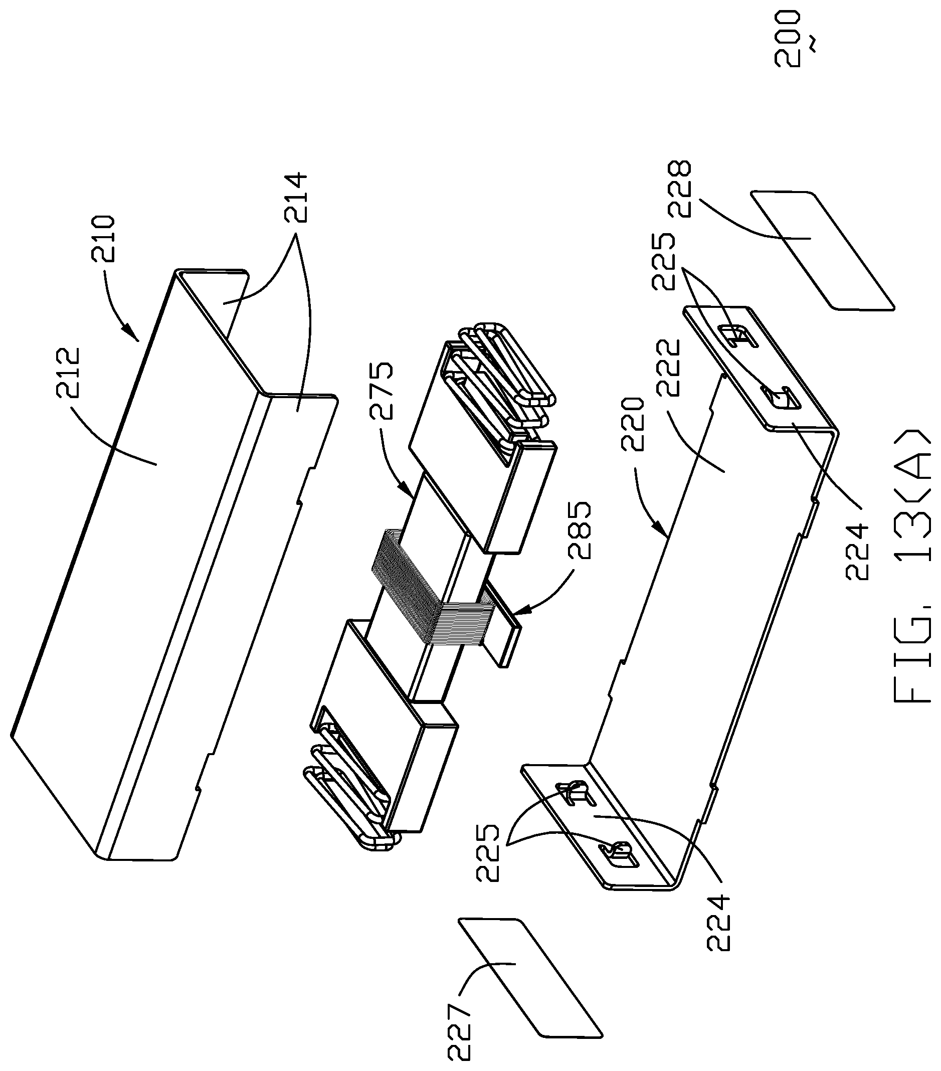
[0026] FIG. 13(A) is a further exploded perspective view of the LRA of FIG. 13;
[0027] FIG. 13(B) is another exploded view of the electrical assembly of FIG. 13(A);
[0028] FIG. 14(A) is a further exploded perspective view of the LRA of FIG. 13(A)
[0029] FIG. 14(B) is another exploded perspective view of the LRA of FIG. 14(A);
[0030] FIG. 15 is a cross-sectional view of the LRA of FIG. 12(A) along line 15-15 without showing the covers;
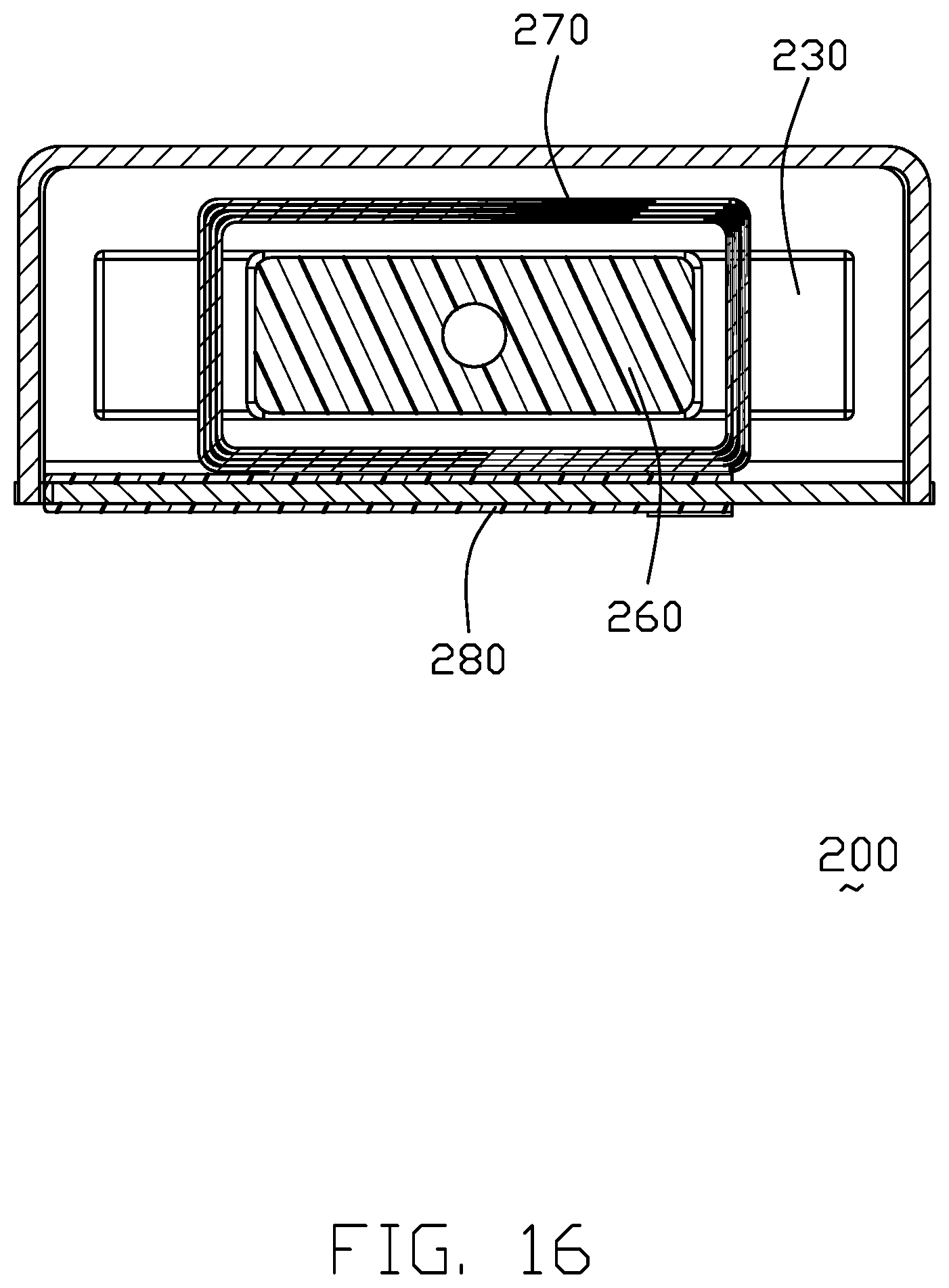
[0031] FIG. 16 is a cross-sectional view of the LRA of FIG. 12(A) along line 16-16;
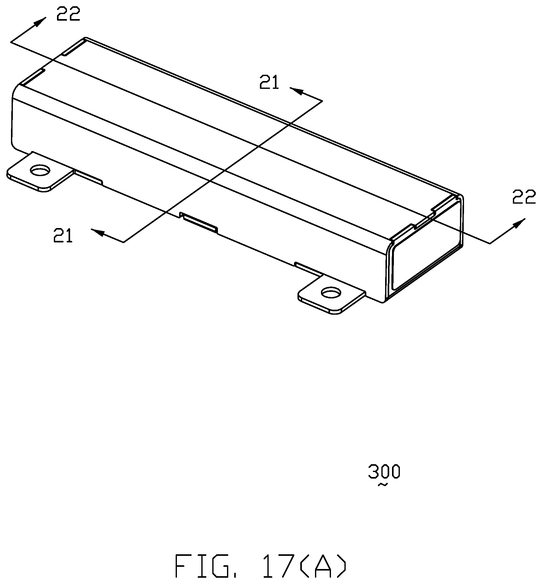
[0032] FIG. 17(A) is a perspective view of an LRA according to a fourth embodiment of the invention;
[0033] FIG. 17(B) is another perspective view of the LRA of FIG. 17(A);
[0034] FIG. 18 is an exploded perspective view of the LRA of FIG. 17(A);
[0035] FIG. 19(A) is a further exploded perspective view of the LRA of FIG. 18;
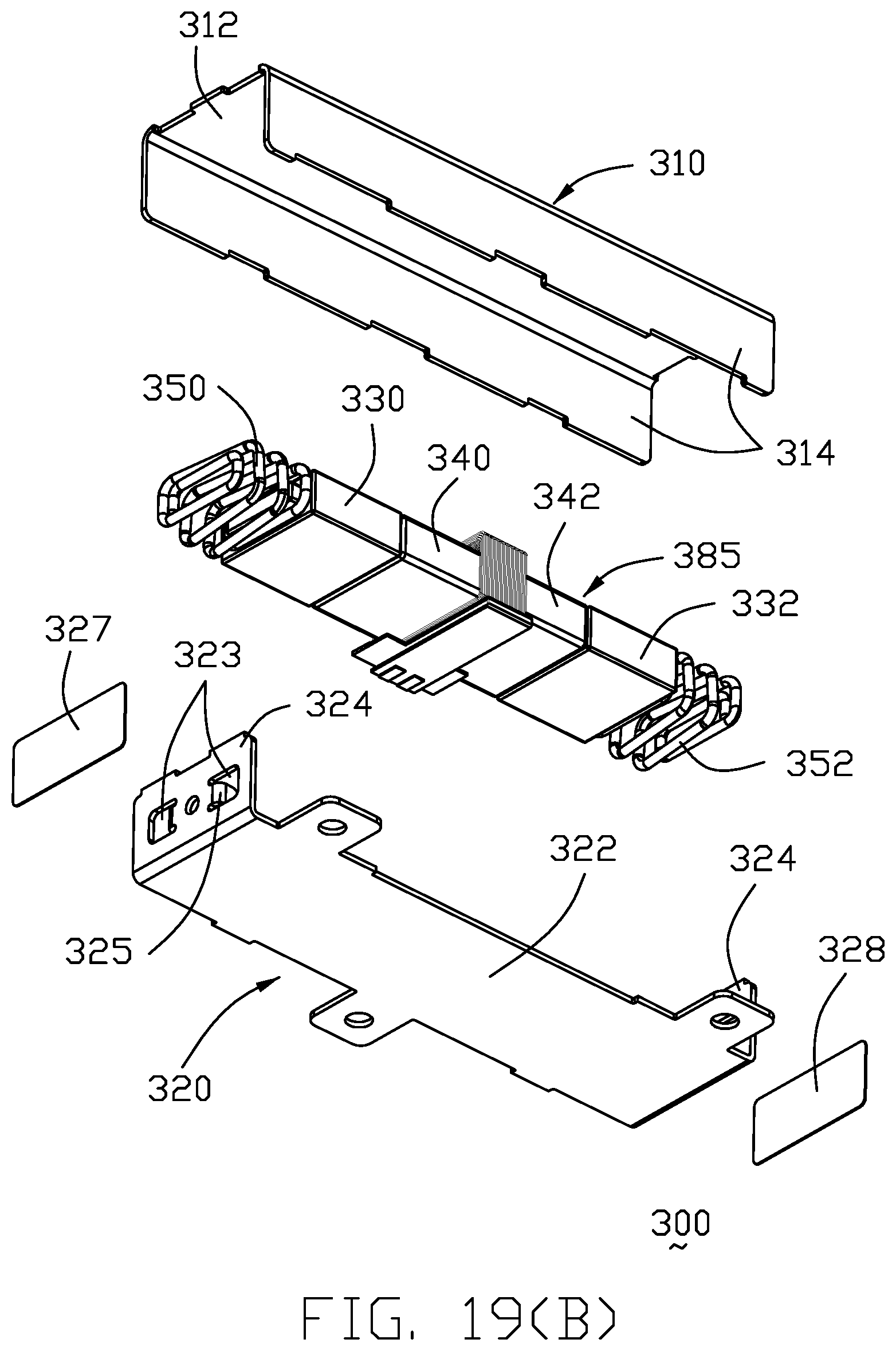
[0036] FIG. 19(B) is another exploded view of the LRA of FIG. 19(A);
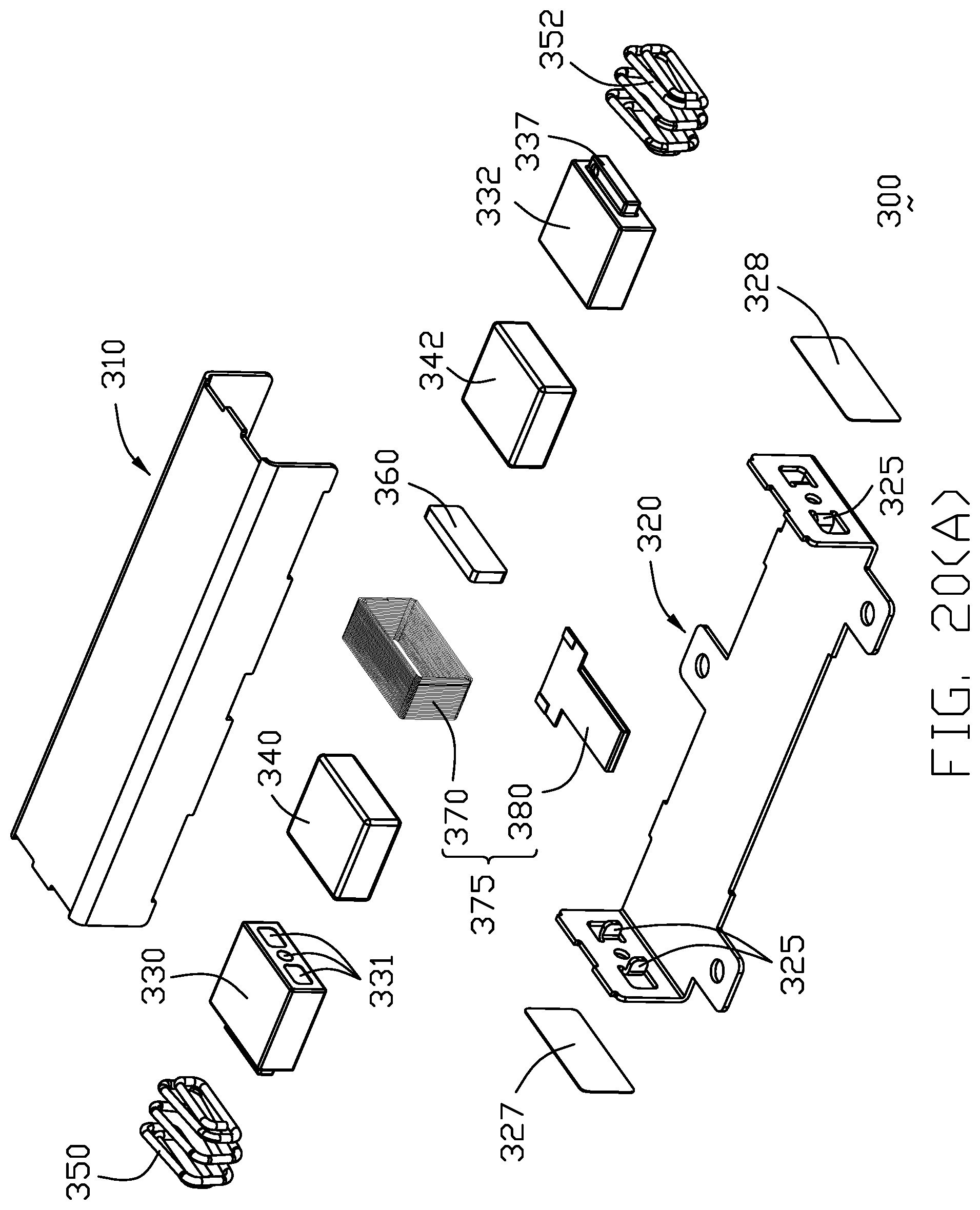
[0037] FIG. 20(A) is a further exploded perspective view of the LRA of FIG. 19(A)
[0038] FIG. 20(B) is another exploded perspective view of the LRA of FIG. 20(A);
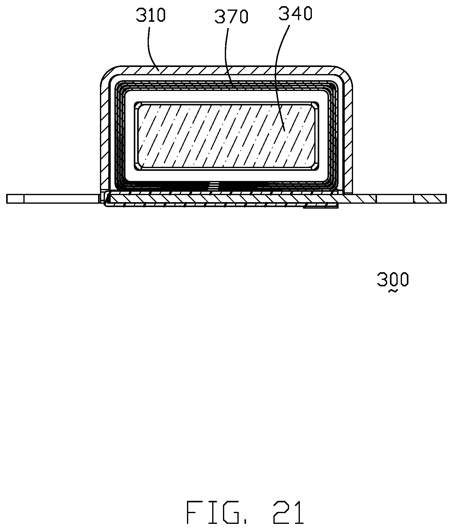
[0039] FIG. 21 is a transverse cross-sectional view of the LRA of FIG. 17(A); and
[0040] FIG. 22 is a longitudinal cross-sectional view of the LRA of FIG. 17(A).
DETAILED DESCRIPTION OF THE PREFERRED EMBODIMENT
[0041] Referring to FIG. 1(A)-6, an LRA 100 includes a metallic case composed of a first half 110 and a second half 120 essentially symmetrical with each other and welded together along the corresponding edges. The first half 110 has a horizontal plate 114, a long side wall 116 and a short side wall 112. The second half 120 has horizontal plate 124, a long side wall 126 and a short side wall 122. The short side wall 112 forms a linear inward embossment 118 with a round hole 119 extending therethrough along a longitudinal direction. The short side wall 122 forms a linear inward embossment 128 with a square hole 129 extending therethrough in the longitudinal direction. The horizontal plate 114 forms a notch 113 to receive a tab 121 extending from the long side wall 126, and the horizontal plate 124 forms another notch 123 to receive the corresponding tab 111 extending from the long side wall 116.
[0042] Inside the case, a magnet assembly 185 includes a first magnet 140 and a second magnet 142 cooperatively sandwiching therebetween along the longitudinal direction a middle magnetizer 160 which has high magnetic permeability and low coercive force compared with the first magnet 140 and the second magnet 142. The first magnet 140 has at the center a round through hole 141 along the longitudinal direction, and the second magnet 142 has at the center another around through hole 143 along the longitudinal direction. The middle magnetizer 160 has at the center a round through hole 161. A first moving mass or support block 130 and a second moving mass or support block 132 cooperatively sandwich the magnet assembly 185 therebetween along the longitudinal direction. The first moving mass 130 has at the center a round through hole 131, and the second moving mass 132 has at the center another round through hole 133. A first rectangular spring 150 is mounted upon the inward embossment 128 while a second rectangular spring 152 is mounted upon the inward embossment 118 whereby the pair of moving masses 130, 132 with the associated magnet assembly 185 therebetween are commonly sandwiched between the pair of rectangular springs 150, 153 tensionally along the longitudinal direction.
[0043] A movable center axle 190 having a square cross-section, extends through the corresponding through holes 141, 143, 161 of the magnet assembly 185 including the pair of magnet 140, 142 with the middle magnetizer 160 therebetween, the corresponding through holes 131, 133 of a pair of moving masses 130, 132, the pair of rectangular springs 150, 152 and terminates, by laser welding, at the corresponding through holes 129, 119 of the embossments 122, 112. Notably, to efficiently receive the corresponding end of the rectangular spring 150, the moving mass 130 forms a protrusion 135 between two spaced plates 136. Similarly, the moving mass 132 forms a protrusion 137 between two spaced plates 1 to receive the corresponding end of the rectangular spring 152. In this embodiment, four corners of the square cross-section of the center axle 190 is curved or rounded so as to facilitate smooth translation of the moving mass 130, 132 and the magnet assembly 185 relative thereto. The through hole of the moving mass may be the square with the rounded corners to comply with the center axel. A coil assembly 175 includes a conductive coil 170 and an FPC (Flexible Printed Circuit) 180 connected to each other wherein the coil 170 is located inside the case to surround the magnet assembly 185 with gaps therebetween while the FPC 180 extends outside of the case for power supply.
[0044] Understandably, when the coil assembly 175 is operated, the magnet assembly 175 along with the pair of moving masses 130, 132 will be oscillated between the pair of springs 150, 152, along the longitudinal or axial direction, thus resulting in haptic vibration.
[0045] FIGS. 7(A)-11 show a second embodiment which is similar to the first embodiment except the case further forms inward protrusions 117 on the horizontal plates 114 and the inward protrusions 127 on the horizontal plate 124 in a vertical direction to be received within the corresponding grooves 157 in the moving mass 130 and the corresponding grooves 150 in the moving mass 132 with gaps so as to guide linear movement of the moving masses 130, 132 to stabilize the whole oscillation of the magnet assembly 185 and the moving masses 130, 132 between the pair of springs 150, 152. Notably, both the first embodiment and the second embodiment show the stationary center shaft/axle 190 along which the magnet assembly 185 and the moving masses 130, 132 are moveable.
[0046] FIGS. 12(A)-16 show a third embodiment in which the center axle does not extend to reach the short side wall but terminate within the moving mass, compared with the first and second embodiments. The LRA 200 includes a metallic case composed of a first half 210 and a second half 220 secured together to commonly form an internal space. The first half 210 includes a horizontal plate 212 and a pair of long side walls 214 while the second half 220 includes another horizontal plate 222 and a pair of end or short side walls 224 wherein each short side wall 224 forms a pair/set of inwardly extending tabs 225 functioning as the spring holder to hold the springs 250, 252 illustrated later. A pair of covers 227, 228 are attached upon the corresponding short side walls 224 to cover the openings derived from the inwardly extending tabs 225.
[0047] Similar to the other two embodiments, a magnet assembly 285 includes a first magnet 240 and a second magnet 242 cooperatively sandwiching a middle magnetizer 260 therebetween along the longitudinal direction. The first magnet 240 has a through hole 241, the second magnet 242 has a through hole 243, and magnetizer 260 has a though hole 261. A first moving mass 230 and a second moving mass 232 cooperatively sandwich the magnet assembly 285 therebetween along the longitudinal direction. The first moving mass 230 has a round blind hole 231, and the second moving mass 232 has a blind round hole 233. A first rectangular spring 250 is mounted upon and a second rectangular spring 252 whereby the pair of moving masses 230, 232 associated with the magnet assembly 285 therebetween are commonly sandwiched between the pair of rectangular springs 250, 252 tensionally in the longitudinal direction.
[0048] A moveable center axle 290 having a square cross-section, extends through the corresponding through holes 241, 243, 261 of the magnet assembly 285 and terminates at the blind holes 231, 233 of the opposite first moving mass 230 and second moving mass 232. Similar to the other two embodiments, the moving mass 230 has the protrusion 235 to capture the rectangular spring 250, and the moving mass 232 has the protrusion 237 to capture the rectangular spring 252. A coil assembly 275 includes conductive coil 270 and an FPC 280 wherein the conductive coil 270 surrounds the magnet assembly 285 with gaps therebetween while the FPC extends outside of the case.
[0049] Understandably, when the coil assembly 275 is operated, the magnet assembly 285 along with the pair of moving masses 230, 232 will be oscillated between the pair of springs 250, 252, along the longitudinal direction, thus resulting in haptic vibration. Notably, in the other two embodiment such a haptic vibration is essentially performed only along the longitudinal direction. Differently, in the third embodiment, because two ends of the center axle 290 no longer secured to the stationary case but embedded within the moveable masses 230, 232 to have the combination of the magnet assembly 285 and the pair of moving masses 230, 232, the haptic vibration is performed further slightly in the vertical direction additionally in comparison with the two other embodiments.
[0050] Referring to FIGS. 17(A)-22, the LRA 300 includes a metallic case composed of a first half 310 and a second half 320 secured together to commonly form an internal space. The first half 310 includes a horizontal plate 312 and a pair of long side walls 314 while the second half 320 includes another horizontal plate 322 and a pair of end or short side walls 324 wherein each short side wall 324 forms a pair/set of inwardly extending tabs 325 functioning as the spring holder to hold the springs 350, 352 illustrated later. A pair of sheet covers 327, 328 are attached upon the corresponding short side walls 324 to cover the openings 323 derived from the inwardly extending tabs 325.
[0051] A magnet assembly 385 includes a first magnet 340 and a second magnet 342 cooperatively sandwiching a middle magnetizer 360 therebetween along the longitudinal direction. The first magnet 340 has a through hole 341, the second magnet 342 has a through hole 343, and magnetizer 360 has a though hole 361. A first moving (weight) mass 330 and a second moving (weight) mass 332 cooperatively sandwich the magnet assembly 385 therebetween along the longitudinal direction. The first moving mass 330 has a set of blind holes 331, and the second moving mass 332 has a set of blind holes 333. A first rectangular spring 350 is mounted upon and a second rectangular spring 352 whereby the pair of moving masses 330, 332 associated with the magnet assembly 385 therebetween are commonly sandwiched between the pair of rectangular springs 350, 352 tensionally in the longitudinal direction.
[0052] The moving mass 330 has the protrusion 335 to capture the rectangular spring 350, and the moving mass 332 has the protrusion 337 to capture the rectangular spring 352. The other end of the spring 350 is captured by the pair of tabs 325 as well as the other end of the spring 352. A coil assembly 375 includes conductive coil 370 and an FPC 380 wherein the conductive coil 370 surrounds the magnet assembly 385 with gaps therebetween while the FPC 380 extends outside of the case.
[0053] The interface between the first moving mass 330 and the first magnet 340 is filled with glue as well as that between the second moving mass 332 and the second magnet 342. The blind holes 331 of the first moving mass 330 are to receive the excessive glue as well as the blind hole 333 of the second moving mass 332. Alternately, an interengaging structure like the interface structure between the moving mass and the spring or the protrusion vs. recess structure, may be applied to the interface between the moving mass and the magnet as long as no radial relative movement therebetween. The interface between the magnetizer 360 and the corresponding magnet 340 or 342 is also applicable as well, if necessary.
[0054] Compared with the previous design, there is no shaft extending through the corresponding magnet assembly and the moving masses so as to ease the manufacturization of the magnet and the moving mass for no consideration of the precise dimension of the holes therein, which requires to comply with the diameter of the shaft. In contrast, in the instant invention the magnet requires no hole and the moving mass requires the holes without necessity of high precision.
* * * * *
D00000
D00001
D00002
D00003
D00004
D00005
D00006
D00007
D00008
D00009
D00010
D00011
D00012

D00013

D00014

D00015

D00016

D00017

D00018

D00019

D00020

D00021

D00022

D00023
D00024

D00025

D00026

D00027

D00028
D00029
D00030

D00031

D00032

D00033
D00034
D00035

D00036
D00037

XML
uspto.report is an independent third-party trademark research tool that is not affiliated, endorsed, or sponsored by the United States Patent and Trademark Office (USPTO) or any other governmental organization. The information provided by uspto.report is based on publicly available data at the time of writing and is intended for informational purposes only.
While we strive to provide accurate and up-to-date information, we do not guarantee the accuracy, completeness, reliability, or suitability of the information displayed on this site. The use of this site is at your own risk. Any reliance you place on such information is therefore strictly at your own risk.
All official trademark data, including owner information, should be verified by visiting the official USPTO website at www.uspto.gov. This site is not intended to replace professional legal advice and should not be used as a substitute for consulting with a legal professional who is knowledgeable about trademark law.