In-home Network Splitter With Reduced Isolation
Bailey; Paul
U.S. patent application number 17/101593 was filed with the patent office on 2021-03-11 for in-home network splitter with reduced isolation. The applicant listed for this patent is PPC BROADBAND, INC.. Invention is credited to Paul Bailey.
| Application Number | 20210075168 17/101593 |
| Document ID | / |
| Family ID | 1000005237456 |
| Filed Date | 2021-03-11 |


| United States Patent Application | 20210075168 |
| Kind Code | A1 |
| Bailey; Paul | March 11, 2021 |
IN-HOME NETWORK SPLITTER WITH REDUCED ISOLATION
Abstract
A splitter includes an input configured to be connected to a cable television (CATV) network. The splitter also includes a first output connected to the input. The first output is configured to be connected to a first subscriber device. The splitter also includes a second output connected to the input. The second output is configured to be connected to a second subscriber device. A path between the first output and the second output is configured to provide an isolation that is less than 30 dB.
| Inventors: | Bailey; Paul; (Camillus, NY) | ||||||||||
| Applicant: |
|
||||||||||
|---|---|---|---|---|---|---|---|---|---|---|---|
| Family ID: | 1000005237456 | ||||||||||
| Appl. No.: | 17/101593 | ||||||||||
| Filed: | November 23, 2020 |
Related U.S. Patent Documents
| Application Number | Filing Date | Patent Number | ||
|---|---|---|---|---|
| 16248152 | Jan 15, 2019 | 10879655 | ||
| 17101593 | ||||
| 62618204 | Jan 17, 2018 | |||
| 62675986 | May 24, 2018 | |||
| Current U.S. Class: | 1/1 |
| Current CPC Class: | H01R 2201/04 20130101; H01R 13/719 20130101; H01R 24/542 20130101; H01R 2201/18 20130101; H01R 24/547 20130101; H04N 7/104 20130101 |
| International Class: | H01R 24/54 20060101 H01R024/54; H04N 7/10 20060101 H04N007/10; H01R 13/719 20060101 H01R013/719 |
Claims
1. A splitter, comprising: an input configured to be connected to a cable television (CATV) network; a reflection-less in-home network adapter (RNA) connected to the input and configured to prevent CATV interference signals from being reflected into the CATV network; a first high-pass filter connected to the RNA; a second high-pass filter connected to the RNA; a third high-pass filter connected to the RNA; a first output connected to the first high-pass filter, wherein the first output is configured to be connected to a first subscriber device; a second output connected to the second high-pass filter, wherein the second output is configured to be connected to a second subscriber device; a third output connected to the third high-pass filter, wherein the third output is configured to be connected to a third subscriber device; wherein a first path is configured to extend between the input and the first output; wherein a second path is configured to extend between the input and the second output; wherein the first path and the second path are configured to have substantially equal resistances, substantially equal impedances, and substantially equal insertion losses; wherein a third path is configured to extend between the first output and the second output; wherein a fourth path is configured to extend between the second output and the third output; wherein the third path and the fourth path are configured to have substantially equal resistances, substantially equal impedances, and substantially equal isolations; and wherein the isolation in the third path, the fourth path, or both is less than 30 dB.
2. The splitter of claim 1, wherein the splitter comprises a resistive Wye-type splitter.
3. The splitter of claim 1, wherein the splitter does not comprise ferrite.
4. The splitter of claim 1, wherein the splitter is band-limited between about 1125 MHz and about 1675 MHz.
5. The splitter of claim 1, wherein the insertion loss in the first path, the second path, or both is greater than 25 dB.
6. A splitter, comprising: an input configured to be connected to a cable television (CATV) network; an electrical circuit component connected to the input; a first high-pass filter connected to the electrical circuit component; a second high-pass filter connected to the electrical circuit component; a first output connected to the first high-pass filter, wherein the first output is configured to be connected to a first subscriber device; and a second output connected to the second high-pass filter, wherein the second output is configured to be connected to a second subscriber device, wherein a path between the first output and the second output is configured to provide an isolation that is less than 30 dB.
7. The splitter of claim 6, wherein the electrical circuit component comprises a reflection-less in-home network adapter (RNA) that is configured to prevent CATV interference signals from being reflected into the CATV network.
8. The splitter of claim 6, wherein the electrical circuit component comprises a third high-pass filter that is configured to provide surge suppression, noise mitigation, or both.
9. The splitter of claim 6, further comprising a plurality of outputs including the first output and the second output, wherein a number of the plurality of outputs is from two to sixteen, and wherein the isolation in the path is less than 25 dB.
10. The splitter of claim 6, further comprising a plurality of outputs including the first output and the second output, wherein a number of the plurality of outputs is from two to four, and wherein the isolation in the path is less than 15 dB.
11. A splitter, comprising: an input configured to be connected to a cable television (CATV) network; a first output connected to the input, wherein the first output is configured to be connected to a first subscriber device; and a second output connected to the input, wherein the second output is configured to be connected to a second subscriber device, and wherein a path between the first output and the second output is configured to provide an isolation that is between 5 dB and 30 dB.
12. The splitter of claim 11, wherein the splitter comprises a resistive Wye-type splitter including the input, the first output, and the second output.
13. The splitter of claim 11, wherein the splitter does not comprise ferrite.
14. The splitter of claim 11, wherein the splitter comprises a reflection-less in-home network adapter (RNA) that is configured to allow signals in a frequency range to be transmitted between the input and the first and second outputs, and to prevent signals outside of the frequency range from being transmitted between the input and the first and second outputs, and wherein the frequency range is between about 1125 MHz and about 1675 MHz.
15. The splitter of claim 11, wherein a path between the input and the first output is configured to provide an insertion loss that is greater than 25 dB.
16. The splitter of claim 11, further comprising a plurality of outputs including the first output and the second output, wherein a number of the plurality of outputs is from two to sixteen, and wherein the isolation in the path is less than 25 dB.
17. The splitter of claim 11, further comprising a plurality of outputs including the first output and the second output, wherein a number of the plurality of outputs is from two to eight, and wherein the isolation in the path is less than 20 dB.
18. The splitter of claim 11, further comprising a plurality of outputs including the first output and the second output, wherein a number of the plurality of outputs is from two to four, and wherein the isolation in the path is less than 15 dB.
19. The splitter of claim 11, wherein the isolation in the path is less than 10 dB.
20. The splitter of claim 11, wherein a path between the input and the first output is configured to provide a different isolation value than a path between the input and the second output.
Description
CROSS-REFERENCE TO RELATED APPLICATIONS
[0001] This application is a continuation of U.S. patent application Ser. No. 16/248,152, filed on Jan. 15, 2019, which claims priority to U.S. Provisional Patent Application No. 62/618,204, filed on Jan. 17, 2018, and U.S. Provisional Patent Application No. 62/675,986, filed on May 24, 2018. The entirety of these applications is incorporated by reference herein.
BACKGROUND
[0002] Typical legacy splitters or power dividers that are used in cable television (CATV) and multimedia over coax alliance (MoCA) networks have predominantly used ferrite transformers to provide a broadband circuit with low input-to-output loss and high output-to-output isolation. These ferrite core splitter circuits are structured in many different ways to include core shape, size, material, winding scheme, external components and additional intermediate circuits to achieve acceptable in-home performance for the CATV bandwidth (e.g., 5-1002 MHz) and MoCA bandwidth (e.g., 1125-1675 MHz). In such ferrite core splitters, however, the extension of bandwidth and/or the addition of intermediate circuits both increase input-to-output losses and may result in high isolation or notches in the output-to-output MoCA band which may cause a loss of in-band signals. Therefore, it would be desirable to have a new splitter to overcome these drawbacks.
SUMMARY
[0003] A splitter is disclosed. The splitter includes an input configured to be connected to a cable television (CATV) network. The splitter also includes a reflection-less in-home network adapter (RNA) connected to the input and configured to prevent CATV interference signals from being reflected into the CATV network. The splitter also includes a first high-pass filter connected to the RNA. The splitter also includes a second high-pass filter connected to the RNA. The splitter also includes a third high-pass filter connected to the RNA. The splitter also includes a first output connected to the first high-pass filter. The first output is configured to be connected to a first subscriber device. The splitter also includes a second output connected to the second high-pass filter. The second output is configured to be connected to a second subscriber device. The splitter also includes a third output connected to the third high-pass filter. The third output is configured to be connected to a third subscriber device. A first path is configured to extend between the input and the first output. A second path is configured to extend between the input and the second output. The first path and the second path are configured to have substantially equal resistances, substantially equal impedances, and substantially equal insertion losses. A third path is configured to extend between the first output and the second output. A fourth path is configured to extend between the second output and the third output. The third path and the fourth path are configured to have substantially equal resistances, substantially equal impedances, and substantially equal isolations. The isolation in the third path, the fourth path, or both is less than 30 dB.
[0004] In another embodiment, the splitter includes an input configured to be connected to a cable television (CATV) network. The splitter also includes a reflection-less in-home network adapter (RNA) connected to the input and configured to prevent CATV interference signals from being reflected into the CATV network. The splitter also includes a first high-pass filter connected to the RNA. The splitter also includes a second high-pass filter connected to the RNA. The splitter also includes a first output connected to the first high-pass filter. The first output is configured to be connected to a first subscriber device. The splitter also includes a second output connected to the second high-pass filter. The second output is configured to be connected to a second subscriber device. A path between the first output and the second output is configured to provide an isolation that is less than 30 dB.
[0005] In another embodiment, the splitter includes an input configured to be connected to a cable television (CATV) network. The splitter also includes a first output connected to the input. The first output is configured to be connected to a first subscriber device. The splitter also includes a second output connected to the input. The second output is configured to be connected to a second subscriber device. A path between the first output and the second output is configured to provide an isolation that is less than 30 dB.
[0006] It will be appreciated that this summary is intended merely to introduce some aspects of the present methods, systems, and media, which are more fully described and/or claimed below. Accordingly, this summary is not intended to be limiting.
BRIEF DESCRIPTION OF THE DRAWINGS
[0007] The accompanying drawings, which are incorporated in and constitute a part of this specification, illustrate embodiments of the present teachings and together with the description, serve to explain the principles of the present teachings.
[0008] FIG. 1 illustrates a schematic view of an in-home network splitter, according to an embodiment.
[0009] FIG. 2A illustrates a graph showing isolation and insertion loss for an equal-output 4-way Wye resistive splitter, according to an embodiment.
[0010] FIG. 2B illustrates a graph showing return loss for the equal-output 4-way Wye resistive splitter, according to an embodiment.
[0011] FIG. 3A illustrates a 4-way in-home network splitter (e.g., ferrite or resistive) with a reflection-less network adapter at the input and high-pass filter (HPF) elements at the output ports, according to an embodiment.
[0012] FIG. 3B illustrates a 4-way in-home network splitter that is a resistive Wye-type, according to an embodiment.
[0013] FIG. 4A illustrates an 8-way in-home network splitter with a reflection-less network adapter at the input and HPF elements at the output ports, according to an embodiment.
[0014] FIG. 4B illustrates an 8-way in-home network splitter with a resistive Wye network and no filters, according to an embodiment.
[0015] FIG. 5 illustrates a graph showing a comparison of the input-to-output insertion loss in the MoCA band (e.g., 1125-1675 MHz) for a ferrite core splitter and a resistive splitter, according to an embodiment.
[0016] FIG. 6 illustrates a graph showing a comparison of the output-to-output isolation in the MoCA band (e.g., 1125-1675 MHz) for a ferrite core splitter and a resistive splitter, according to an embodiment.
DETAILED DESCRIPTION
[0017] Embodiments of the present disclosure may provide an in-home network resistive splitter that has an applied band-limitation (e.g., to 1125-1675 MHz), which allows for the alternative circuit design for improved in-home or MoCA band radio-frequency (RF) performance, thereby differing from conventional broadband CATV splitters. Resistive splitters are not typically used in CATV applications due to their high input-to-output insertion loss and low output isolation compared to conventional ferrite core splitters. Currently, the telecom industry and CATV operators are transitioning from a combined full access and MoCA network architecture to a semi-isolated in-home network architecture, which may benefit from the resistive splitters disclosed herein. As used herein, a full access and MoCA network allows all equipment to access the outside CATV distribution Network or CMTS (e.g., head end) while a semi-isolated in-home network architecture refers to a network including a combination of access and non-access equipment, where the access equipment (e.g., such as modems, gateways and DVRs) has access outside the home, and the non-access equipment such as set top boxes are 100% isolated within the home and coupled only to the access equipment via the in-home or MoCA band. The functionality of the resistive splitters may be further improved with the addition of supporting adaptor circuits that improve the coupling between different networks such as CATV and MoCA, or provide DC blocking, lightning (e.g., surge/ESD) protection, or low-frequency noise ingress mitigation. The resistive splitters may be cascaded in series as-is, or provided with modifications to the resistive splitters, where the input port resistor is decreased or removed, thereby decreasing through-loss by as much as 2 dB.
[0018] Non-ferrite splitter architectures within the MoCA-only network can improve the quality of the MoCA band performance. The resistive splitter has about the same input-to-output insertion loss as the ferrite splitter, but it has less output-to-output isolation that is substantially flatter, making it a good fit for use within the MoCA-only network. This structure can increase the output port count while sustaining improved in-band flatness. For example, a resistive splitter with 12 outputs has less than 22 dB of output isolation, which is roughly the same as a 2-output ferrite splitter. Thus, the resistive splitter disclosed herein may improve the split count and MoCA in-band quality.
[0019] The resistive splitter may be an in-home-network-only splitter with reduced isolation between the outputs. The resistive splitter may be a resistive Wye-type splitter where R=Zo(N-1)/(N+1), where R=resistance, Zo=impedance, and N=the number of matched outputs. The resistive Wye-type splitter may be selected over the delta-type splitter because it can more easily be adapted to an N-way splitter configuration. Each path of the Wye-type N-port circuit (e.g., from the input to any output or from any output to any other output) may have a series resistance of substantially equal value. Each path of the Wye-type N-port circuit may have a substantially equivalent insertion loss and/or isolation. The resistive splitter can be deployed anywhere within the in-home network to provide extended quantity of premises equipment outputs. The resistive splitter may have a substantially flat passband response. The resistive splitter may have better passive intermodulation (PIM) performance than the conventional non-linear ferrite splitter. The resistive splitter containing high-pass noise mitigating or surge and esd protection may use a reflection-less in-home network adapter (RNA) when coupled to a CATV access network device to prevent CATV interference signals from being reflected back into the CATV network. In the MoCA band input-to-output, insertion loss is substantially equal for both resistive splitters and ferrite splitters. However, in the MoCA band, input-to-output isolation is different between resistive splitters and ferrite splitters. More particularly, ferrite splitters have excessive isolation beyond 6 splits and may require secondary circuits such as diplex bridging to achieve a functional in-home (e.g., MoCA) network, whereas resistive splitters can provide 25 or more splits before nearing a functional 30 dB isolation limit in addition to providing a significantly flatter response.
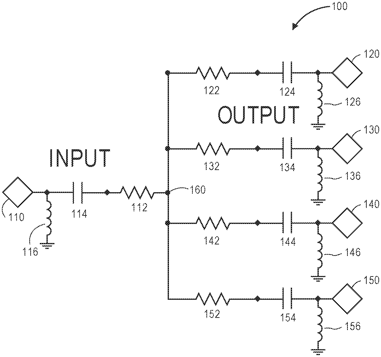
[0020] FIG. 1 illustrates an in-home network splitter 100, according to an embodiment. As shown, the splitter 100 includes an input 110 and one or more outputs (four are shown: 120, 130, 140, 150). A resistor 112 and a capacitor 114 may be in series between the input 110 and a split point 160. Similarly, a resistor 122, 132, 142, 152 and a capacitor 124, 134, 144, 154 may be in series between the split point 160 and each respective output 120, 130, 140, 150. In at least one embodiment, each resistor may have substantially the same value (e.g., 45 ohms), and each capacitor may have substantially the same value (e.g., 1000 pF). In at least one embodiment, one or more of the (e.g., blocking) capacitors may be omitted.
[0021] The splitter 100 may be or include a resistive 4-way Wye splitter with DC block caps at the ports. In an example, for Zo=75 ohm and N=4; R=Zo*(N+1)/(N-1)=45 ohm. The splitter 100 may be used in one or more of the applications described in U.S. patent application Ser. No. 15/638,933, which is incorporated herein by reference. In at least one embodiment, shunt chokes or coils 116, 126, 136, 146, 156 may be added to further improve the DC blocking, surge suppression, and/or noise mitigation.
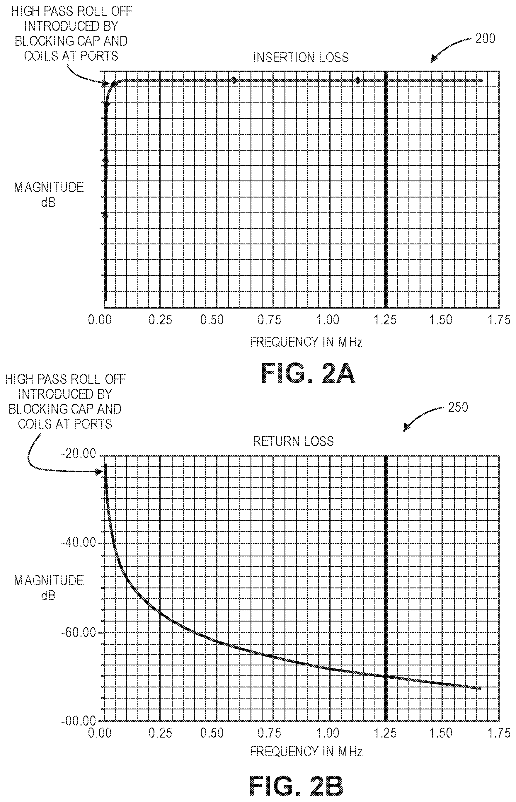
[0022] FIG. 2A illustrates a graph 200 showing insertion loss and isolation for the equal-output 4-way Wye resistive splitter 100, according to an embodiment. The X-axis is frequency in MHz, and the Y-axis is magnitude in dB. In a symmetric or balanced design, the insertion loss is substantially equivalent to the isolation at/in all paths. The input-to-output insertion loss (e.g., S12, S13, S14 . . . )=12 dB at 1125-1675 MHz. The output-to-output isolation (e.g., from output 120 to output 130, from output 130 to output 140, and/or from output 140 to output 150)=12 dB at 1125-1675 MHz. The insertion loss and isolation are substantially overlapping in the graph 200.
[0023] Balanced wye-type resistive splitters are symmetrical in design. Thus, their insertion loss and isolation are the same parameter and represent the magnitude of loss between any two ports. In some cases, the circuit may be unbalanced with differing resistance values, resulting in differing insertion loss or isolation values between various combinations of ports.
[0024] FIG. 2B illustrates a graph 250 showing return loss for the equal-output 4-way Wye resistive splitter 100, according to an embodiment. The return loss is nearly ideal, less the effect of the caps introducing a high pass roll off at low frequency. The ideal return loss for all ports (e.g., at the input 110 or any of the outputs 120, 130, 140, 150)=60 dB at 1125-1675 MHz. The reactive component or DC blocking cap is added for realism and adds curvature to the output response graphs. In at least one embodiment, the focus of the in-home network splitter response is in the MoCa band (e.g., 1125-1675 MHz). FIGS. 2A and 2B also show the high pass roll-off introduced by blocking caps and coils at the ports.
[0025] FIG. 3A illustrates a 4-way in-home network splitter 300 (e.g., ferrite or resistive) with a reflection-less network adapter 310, according to an embodiment. The adapter 310 may be deployed when the output ports are configured with high-pass elements for DC blocking, surge suppressing, and noise mitigation. High-pass filter (HPF) elements 321-324 may be connected to the output ports. The HPF elements 321-324 may be any combination of series DC blocking capacitance and shunt coils. When the HPF elements 321-324 are used, the RNA 310 may be connected to the input port to prevent reflections in the CATV bandwidth. FIG. 3B illustrates a 4-way in-home network splitter 350 that is a resistive Wye-type, according to an embodiment.
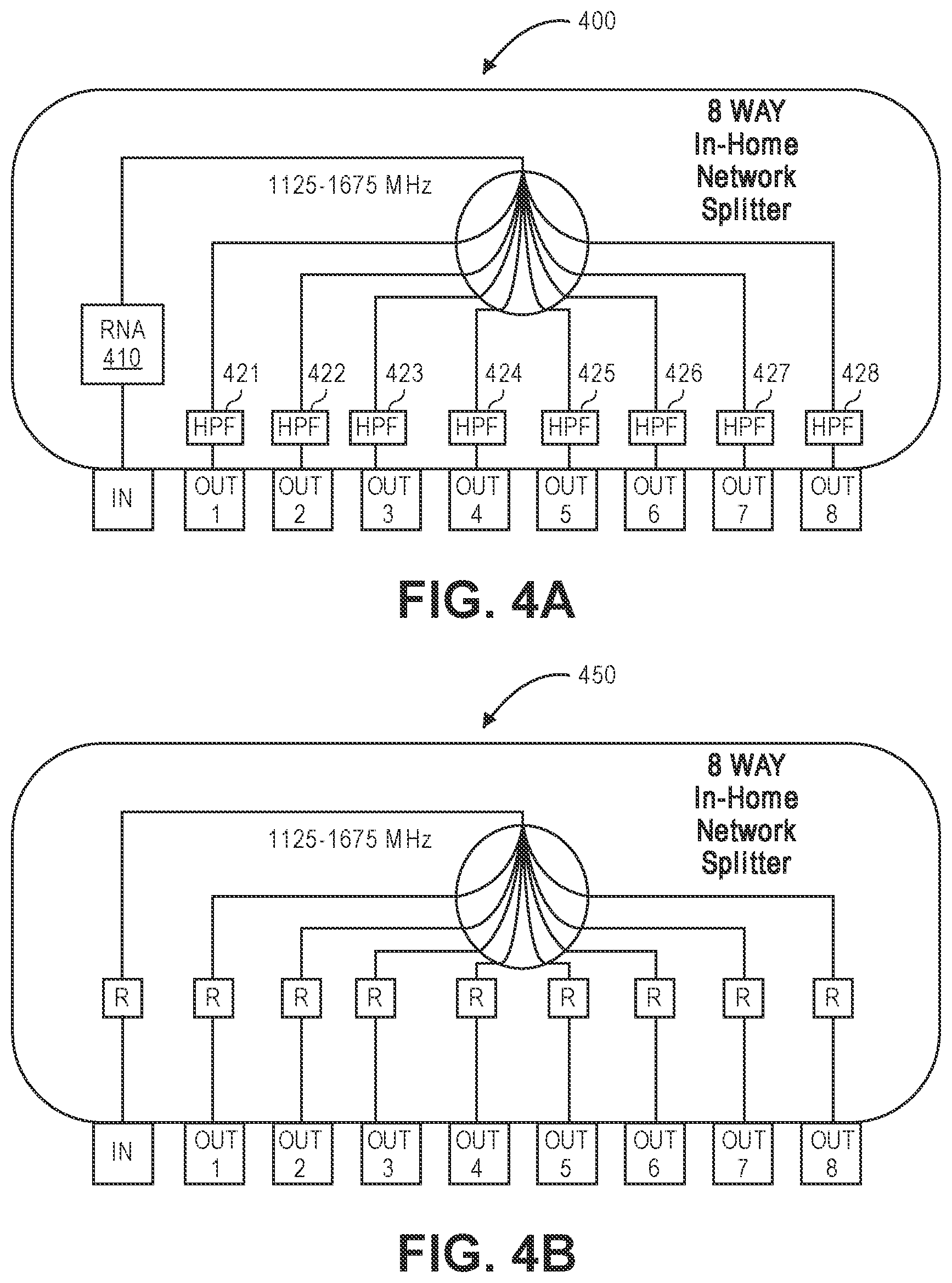
[0026] FIG. 4A illustrates an 8-way in-home network splitter 400 with a reflection-less network adapter (RNA) 410, according to an embodiment. The splitter 400 may be a high-pass filter for noise isolation. In at least one embodiment, low-order high-pass filters can be deployed at one or more (e.g., all) ports for surge protection and low-frequency noise ingress mitigation. High-pass filter (HPF) elements 421-428 may be connected to the output ports. The HPF elements 421-428 may be any combination of series DC blocking capacitance and shunt coils. When the HPF elements 421-428 are used, the RNA 410 should be connected to the input port to prevent reflections in the CATV bandwidth. FIG. 4B illustrates an 8-way in-home network splitter 450 with a resistive Wye network and no filters, according to an embodiment.
[0027] FIG. 5 illustrates a graph 500 showing input-to-output insertion loss in the MoCA band (e.g., 1125-1675 MHz) for a ferrite core splitter 510 and a resistive splitter 520, according to an embodiment. In the ferrite core splitter 510, MoCA insertion loss degrades significantly. As shown, in the ferrite core splitter 510, the insertion loss is less than about 10 dB up to about 3 splits or output ports. The insertion loss drops to about 22 dB at 16 splits or output ports. In the resistive Wye splitter 520, MoCA insertion loss is less than about 30 dB up to about 20 or about 25 splits or output ports.
[0028] FIG. 6 illustrates a graph 600 showing output-to-output isolation in the MoCA band (e.g., 1125-1675 MHz) for a ferrite core splitter 610 and a resistive splitter 620, according to an embodiment. In the ferrite core splitter 610, MoCA isolation degrades significantly. The conventional ferrite core splitter 610 increases in isolation as the number of outputs increases. In contrast, the resistive splitter 620 has a depreciating increase in isolation as the number of outputs increases. In other words, the isolation continues to increase as the number of outputs increases, but by smaller and smaller amounts with the addition of each output. Thus, the resistive splitter 620 may be an improved option for higher-split applications such as used within the in-home network. Although not depicted in the Figures, the in-home network splitters may utilize wire wound chokes or coils shunt to ground at the RF ports to further enhance the surge or noise ingress suppression.
[0029] As shown, in the ferrite core splitter 610, the isolation is less than about 30 dB beyond 4 splits and requires additional circuitry such as a MoCA bridging diplexers to make it functional. The isolation drops to about 90 dB at 16 splits or output ports. In the resistive splitter 620, MoCA isolation is less than about 15 dB across 4 splits or outputs, less than about 20 dB across 8 splits or outputs, less than about 25 dB across 16 splits or outputs, and less than about 30 dB across 25 splits or output ports.
[0030] Some in-home network splitters that employ shunt chokes or coils at the output ports, to enhance the low-frequency noise mitigations, surge and esd protection, may also employ a resistive network adapter at the input port to prevent reflections in the CATV band.
[0031] While various aspects and embodiments have been disclosed herein, other aspects and embodiments will be apparent to those skilled in the art. The various aspects and embodiments disclosed herein are for purposes of illustration and are not intended to be limiting, with the true scope and spirit being indicated by the following claims. The present disclosure is not to be limited in terms of the particular embodiments described in this application, which are intended as illustrations of various aspects. Many modifications and variations can be made without departing from its spirit and scope, as will be apparent to those skilled in the art. Functionally equivalent apparatuses within the scope of the disclosure, in addition to those enumerated herein will be apparent to those skilled in the art from the foregoing descriptions. Such modifications and variations are intended to fall within the scope of the appended claims. The present disclosure is to be limited only by the terms of the appended claims, along with the full scope of equivalents to which such claims are entitled. It is also to be understood that the terminology used herein is for the purpose of describing particular embodiments only, and is not intended to be limiting.
[0032] With respect to the use of substantially any plural and/or singular terms herein, those having skill in the art can translate from the plural to the singular and/or from the singular to the plural as is appropriate to the context and/or application. The various singular/plural permutations may be expressly set forth herein for sake of clarity.
[0033] It will be understood by those within the art that, in general, terms used herein, and especially in the appended claims (e.g., bodies of the appended claims) are generally intended as "open" terms (e.g., the term "including" should be interpreted as "including but not limited to," the term "having" should be interpreted as "having at least," the term "includes" should be interpreted as "includes but is not limited to," etc.). It will be further understood by those within the art that if a specific number of an introduced claim recitation is intended, such an intent will be explicitly recited in the claim, and in the absence of such recitation no such intent is present. For example, as an aid to understanding, the following appended claims may contain usage of the introductory phrases "at least one" and "one or more" to introduce claim recitations. However, the use of such phrases should not be construed to imply that the introduction of a claim recitation by the indefinite articles "a" or "an" limits any particular claim containing such introduced claim recitation to embodiments containing only one such recitation, even when the same claim includes the introductory phrases "one or more" or "at least one" and indefinite articles such as "a" or "an" (e.g., "a" and/or "an" should be interpreted to mean "at least one" or "one or more"); the same holds true for the use of definite articles used to introduce claim recitations. In addition, even if a specific number of an introduced claim recitation is explicitly recited, those skilled in the art will recognize that such recitation should be interpreted to mean at least the recited number (e.g., the bare recitation of "two recitations," without other modifiers, means at least two recitations, or two or more recitations). Furthermore, in those instances where a convention analogous to "at least one of A, B, and C, etc." is used, in general such a construction is intended in the sense one having skill in the art would understand the convention (e.g., " a system having at least one of A, B, and C" would include but not be limited to systems that have A alone, B alone, C alone, A and B together, A and C together, B and C together, and/or A, B, and C together, etc.). In those instances where a convention analogous to "at least one of A, B, or C, etc." is used, in general such a construction is intended in the sense one having skill in the art would understand the convention (e.g., " a system having at least one of A, B, or C" would include but not be limited to systems that have A alone, B alone, C alone, A and B together, A and C together, B and C together, and/or A, B, and C together, etc.). It will be further understood by those within the art that virtually any disjunctive word and/or phrase presenting two or more alternative terms, whether in the description, claims, or drawings, should be understood to contemplate the possibilities of including one of the terms, either of the terms, or both terms. For example, the phrase "A or B" will be understood to include the possibilities of "A" or "B" or "A and B." In addition, where features or aspects of the disclosure are described in terms of Markush groups, those skilled in the art will recognize that the disclosure is also thereby described in terms of any individual member or subgroup of members of the Markush group.
* * * * *
D00000
D00001
D00002
D00003
D00004
D00005
XML
uspto.report is an independent third-party trademark research tool that is not affiliated, endorsed, or sponsored by the United States Patent and Trademark Office (USPTO) or any other governmental organization. The information provided by uspto.report is based on publicly available data at the time of writing and is intended for informational purposes only.
While we strive to provide accurate and up-to-date information, we do not guarantee the accuracy, completeness, reliability, or suitability of the information displayed on this site. The use of this site is at your own risk. Any reliance you place on such information is therefore strictly at your own risk.
All official trademark data, including owner information, should be verified by visiting the official USPTO website at www.uspto.gov. This site is not intended to replace professional legal advice and should not be used as a substitute for consulting with a legal professional who is knowledgeable about trademark law.