Image Processing Method And Apparatus, Image Device, And Storage Medium
WANG; Min ; et al.
U.S. patent application number 17/102331 was filed with the patent office on 2021-03-11 for image processing method and apparatus, image device, and storage medium. The applicant listed for this patent is Beijing Sensetime Technology Development Co., Ltd.. Invention is credited to Wentao LIU, Lizhuang MA, Chen QIAN, Min WANG, Fubao XIE.
| Application Number | 20210074004 17/102331 |
| Document ID | / |
| Family ID | 1000005251245 |
| Filed Date | 2021-03-11 |


| United States Patent Application | 20210074004 |
| Kind Code | A1 |
| WANG; Min ; et al. | March 11, 2021 |
IMAGE PROCESSING METHOD AND APPARATUS, IMAGE DEVICE, AND STORAGE MEDIUM
Abstract
Embodiments of the present disclosure disclose an image processing method and apparatus, an image device, and a storage medium. The image processing method includes: obtaining an image; obtaining a feature of a part of a target based on the image; determining movement information of the part based on the feature; and controlling movement of a corresponding part in a controlled model according to the movement information.
| Inventors: | WANG; Min; (Beijing, CN) ; XIE; Fubao; (Beijing, CN) ; LIU; Wentao; (Beijing, CN) ; QIAN; Chen; (Beijing, CN) ; MA; Lizhuang; (Beijing, CN) | ||||||||||
| Applicant: |
|
||||||||||
|---|---|---|---|---|---|---|---|---|---|---|---|
| Family ID: | 1000005251245 | ||||||||||
| Appl. No.: | 17/102331 | ||||||||||
| Filed: | November 23, 2020 |
Related U.S. Patent Documents
| Application Number | Filing Date | Patent Number | ||
|---|---|---|---|---|
| PCT/CN2020/072526 | Jan 16, 2020 | |||
| 17102331 | ||||
| Current U.S. Class: | 1/1 |
| Current CPC Class: | G06K 9/00315 20130101; G06T 2207/30201 20130101; G06T 7/73 20170101; G06T 13/40 20130101; G06T 2200/04 20130101; G06T 7/246 20170101 |
| International Class: | G06T 7/246 20060101 G06T007/246; G06T 13/40 20060101 G06T013/40; G06K 9/00 20060101 G06K009/00; G06T 7/73 20060101 G06T007/73 |
Foreign Application Data
| Date | Code | Application Number |
|---|---|---|
| Jan 18, 2019 | CN | 201910049830.6 |
| Apr 30, 2019 | CN | 201910362107.3 |
Claims
1. An image processing method, comprising: obtaining an image; obtaining a feature of a part of a target based on the image; determining movement information of the part based on the feature; and controlling movement of a corresponding part in a controlled model according to the movement information.
2. The method according to claim 1, wherein obtaining the feature of the part of the target based on the image comprises: obtaining a first-type feature of a first-type part of the target based on the image; and/or obtaining a second-type feature of a second-type part of the target based on the image.
3. The method according to claim 2, wherein obtaining the first-type feature of the first-type part of the target based on the image comprises: obtaining an expression feature of a head and an intensity coefficient of the expression feature based on the image.
4. The method according to claim 3, wherein obtaining the intensity coefficient of the expression feature based on the image comprises: obtaining, based on the image, an intensity coefficient that represents each sub-part in the first-type part.
5. The method according to claim 3, wherein determining the movement information of the part based on the feature comprises: determining movement information of the head based on the expression feature and the intensity coefficient; and controlling the movement of the corresponding part in the controlled model according to the movement information comprises: controlling an expression change of a head in the controlled model according to the movement information of the head.
6. The method according to claim 2, wherein obtaining the second-type feature of the second-type part of the target based on the image comprises: obtaining position information of a key point of the second-type part of the target based on the image; and determining the movement information of the part based on the feature comprises: determining movement information of the second-type part based on the position information.
7. The method according to claim 6, wherein obtaining the position information of the key point of the second-type part of the target based on the image comprises: obtaining a first coordinate of a support key point of the second-type part of the target based on the image; and obtaining a second coordinate based on the first coordinate.
8. The method according to claim 7, wherein obtaining the first coordinate of the support key point of the second-type part of the target based on the image comprises: obtaining a first 2-Dimensional (2D) coordinate of the support key point of the second-type part based on a 2D image; and obtaining the second coordinate based on the first coordinate comprises: obtaining a first 3-Dimensional (3D) coordinate corresponding to the first 2D coordinate based on the first 2D coordinate and a conversion relationship between a 2D coordinate and a 3D coordinate.
9. The method according to claim 7, wherein obtaining the first coordinate of the support key point of the second-type part of the target based on the image comprises: obtaining a second 3D coordinate of the support key point of the second-type part of the target based on a 3D image; and obtaining the second coordinate based on the first coordinate comprises: obtaining a third 3D coordinate based on the second 3D coordinate.
10. The method according to claim 9, wherein obtaining the third 3D coordinate based on the second 3D coordinate comprises: correcting, based on the second 3D coordinate, a 3D coordinate of a support key point corresponding to an occluded portion of the second-type part in the 3D image, to obtain the third 3D coordinate.
11. The method according to claim 6, wherein determining the movement information of the second-type part based on the position information comprises: determining a quaternion of the second-type part based on the position information.
12. The method according to claim 6, wherein obtaining the position information of the key point of the second-type part of the target based on the image comprises: obtaining first position information of a support key point of a first part in the second-type part; and obtaining second position information of a support key point of a second part in the second-type part.
13. The method according to claim 12, wherein determining the movement information of the second-type part based on the position information comprises: determining movement information of the first part according to the first position information; and determining movement information of the second part according to the second position information.
14. The method according to claim 13, wherein controlling the movement of the corresponding part in the controlled model according to the movement information comprises: controlling movement of a part in the controlled model corresponding to the first part according to the movement information of the first part; and controlling movement of a part in the controlled model corresponding to the second part according to the movement information of the second part.
15. The method according to claim 12, wherein the first part is a torso; and/or the second part is an upper limb, a lower limb, or four limbs.
16. An image device, comprising: a memory storing computer-executable instructions; and a processor coupled to the memory, wherein the processor is configured to obtain an image; obtain a feature of a part of a target based on the image; determine movement information of the part based on the feature; and control movement of a corresponding part in a controlled model according to the movement information.
17. The device according to claim 16, wherein obtaining the feature of the part of the target based on the image comprises: obtaining a first-type feature of a first-type part of the target based on the image; and/or obtaining a second-type feature of a second-type part of the target based on the image.
18. The device according to claim 17, wherein obtaining the first-type feature of the first-type part of the target based on the image comprises: obtaining an expression feature of a head and an intensity coefficient of the expression feature based on the image.
19. The device according to claim 17, wherein obtaining the second-type feature of the second-type part of the target based on the image comprises: obtaining position information of a key point of the second-type part of the target based on the image; and determining the movement information of the part based on the feature comprises: determining movement information of the second-type part based on the position information.
20. A non-volatile computer storage medium storing computer-executable instructions that are executed by a processor to: obtain an image; obtain a feature of a part of a target based on the image; determine movement information of the part based on the feature; and control movement of a corresponding part in a controlled model according to the movement information.
Description
CROSS REFERENCE TO RELATED APPLICATION
[0001] The present application is a continuation of International Application No. PCT/CN2020/072526, filed on Jan. 16, 2020, which claims priority to Chinese Patent Application No. 201910049830.6, filed on Jan. 18, 2019 and entitled "IMAGE PROCESSING METHOD AND APPARATUS, IMAGE DEVICE, AND STORAGE MEDIUM", and Chinese Patent Application No. 201910362107.3, filed on Apr. 30, 2019 and entitled "IMAGE PROCESSING METHOD AND APPARATUS, IMAGE DEVICE, AND STORAGE MEDIUM", all of which are incorporated herein by reference in their entirety.
TECHNICAL FIELD
[0002] The present disclosure relates to the field of information technologies, and in particular, to an image processing method and apparatus, an image device, and a storage medium.
BACKGROUND
[0003] With the development of information technologies, users perform online teaching, webcasting, motion sensing games, etc. by means of video recording. However, in some cases, for example, motion sensing games require users to wear special motion sensing devices to detect the activities of their own body, etc. so as to control game characters. However, during online teaching or webcasting, the user's face or body are completely exposed to a network. This may involve a user's privacy issue, and may also involve an information security issue. In order to solve the privacy or security issue, a face image may be covered by mosaics and the like, but this may affect the video effect.
SUMMARY
[0004] In this regard, embodiments of the present disclosure provide an image processing method and apparatus, an image device, and a storage medium.
[0005] In a first aspect, the present disclosure provides an image processing method, including:
[0006] obtaining an image; obtaining a feature of a part of a target based on the image; determining movement information of the part based on the feature; and controlling the movement of a corresponding part in a controlled model according to the movement information.
[0007] Based on the foregoing solution, obtaining the feature of the part of the target based on the image includes: obtaining a first-type feature of a first-type part of the target based on the image; and/or obtaining a second-type feature of a second-type part of the target based on the image.
[0008] Based on the foregoing solution, obtaining the first-type feature of the first-type part of the target based on the image includes: obtaining an expression feature of a head and an intensity coefficient of the expression feature based on the image.
[0009] Based on the foregoing solution, obtaining the intensity coefficient of the expression feature based on the image includes: obtaining, based on the image, an intensity coefficient that represents each sub-part in the first-type part.
[0010] Based on the foregoing solution, determining the movement information of the part based on the feature includes: determining the movement information of the head based on the expression feature and the intensity coefficient; and controlling the movement of the corresponding part in the controlled model according to the movement information includes: controlling an expression change of a head in the controlled model according to the movement information of the head.
[0011] Based on the foregoing solution, obtaining the second-type feature of the second-type part of the target based on the image includes: obtaining position information of a key point of the second-type part of the target based on the image; and determining the movement information of the part based on the feature includes: determining movement information of the second-type part based on the position information.
[0012] Based on the foregoing solution, obtaining the position information of the key point of the second-type part of the target based on the image includes: obtaining a first coordinate of a support key point of the second-type part of the target based on the image; and obtaining a second coordinate based on the first coordinate.
[0013] Based on the foregoing solution, obtaining the first coordinate of the support key point of the second-type part of the target based on the image includes: obtaining a first 2-Dimensional (2D) coordinate of the support key point of the second-type part based on a 2D image; and obtaining the second coordinate based on the first coordinate includes: obtaining a first 3-Dimensional (3D) coordinate corresponding to the first 2D coordinate based on the first 2D coordinate and a conversion relationship between a 2D coordinate and a 3D coordinate.
[0014] Based on the foregoing solution, obtaining the first coordinate of the support key point of the second-type part of the target based on the image includes: obtaining a second 3D coordinate of the support key point of the second-type part of the target based on a 3D image; and obtaining the second coordinate based on the first coordinate includes: obtaining a third 3D coordinate based on the second 3D coordinate.
[0015] Based on the foregoing solution, obtaining the third 3D coordinate based on the second 3D coordinate includes: correcting, based on the second 3D coordinate, a 3D coordinate of a support key point corresponding to an occluded portion of the second-type part in the 3D image, so as to obtain the third 3D coordinate.
[0016] 1161Based on the foregoing solution, determining the movement information of the second-type part based on the position information includes: determining a quaternion of the second-type part based on the position information.
[0017] Based on the foregoing solution, obtaining the position information of the key point of the second-type part of the target based on the image includes: obtaining first position information of the support key point of a first part in the second-type part; and obtaining second position information of the support key point of a second part in the second-type part.
[0018] Based on the foregoing solution, determining the movement information of the second-type part based on the position information includes: determining movement information of the first part according to the first position information; and determining movement information of the second part according to the second position information.
[0019] Based on the foregoing solution, controlling the movement of the corresponding part in the controlled model according to the movement information includes: controlling movement of a part in the controlled model corresponding to the first part according to the movement information of the first part; and controlling movement of a part in the controlled model corresponding to the second part according to the movement information of the second part.
[0020] Based on the foregoing solution, the first part is a torso; and/or the second part is upper limbs, lower limbs, or four limbs.
[0021] In a second aspect, the present disclosure provides an image processing apparatus, including:
[0022] a first obtaining module, configured to obtain an image; a second obtaining module, configured to obtain a feature of a part of a target based on the image; a first determining module, configured to determine movement information of the part based on the feature; and a control module, configured to control the movement of a corresponding part in a controlled model according to the movement information.
[0023] In a third aspect, the present disclosure provides an image device, including: a memory; and a processor, connected to the memory and configured to execute computer-executable instructions stored on the memory so as to implement the image processing method according to any one of the foregoing items.
[0024] In a fourth aspect, the present disclosure provides a non-volatile computer storage medium, having computer-executable instructions stored thereon, where after the computer-executable instructions are executed by a processor, the image processing method according to any one of the foregoing items is implemented.
[0025] According to the technical solutions provided by the embodiments of the present disclosure, the feature of the part of the target is obtained according to the obtained image, then movement information of the part is obtained based on the feature of the part, and finally the movement of the corresponding part in the controlled model is controlled according to the movement information. In this way, when the controlled model is used to simulate the movement of the target for live video streaming, the movement of the controlled model may be precisely controlled, so that the controlled model precisely simulates the movement of the target. On the one hand, live video streaming is achieved, and on the other hand, user privacy is protected.
BRIEF DESCRIPTION OF THE DRAWINGS
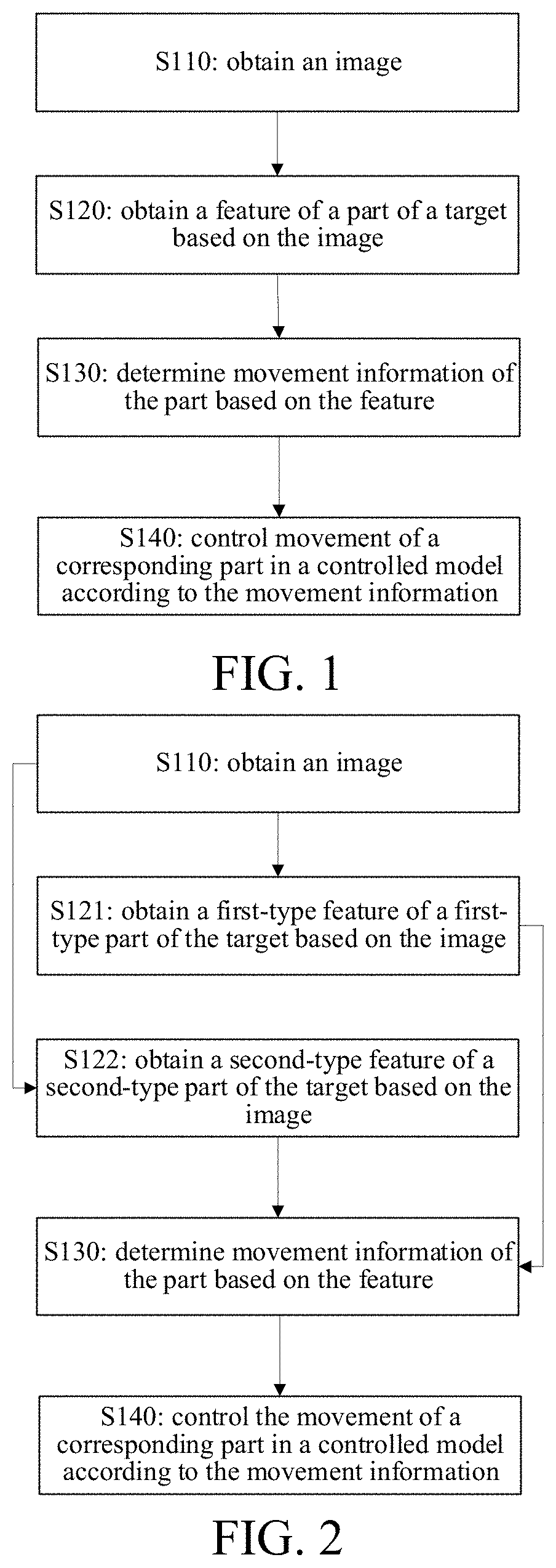
[0026] FIG. 1 is a schematic flowchart of an image processing method provided by embodiments of the present disclosure.
[0027] FIG. 2 is a schematic flowchart of an image processing method provided by other embodiments of the present disclosure.
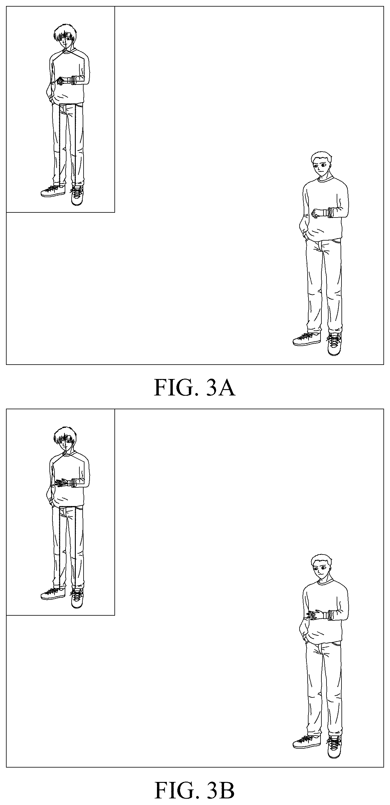
[0028] FIGS. 3A to 3C are schematic diagrams of simulating a change in a captured user's hand movement by a controlled model provided by the embodiments.
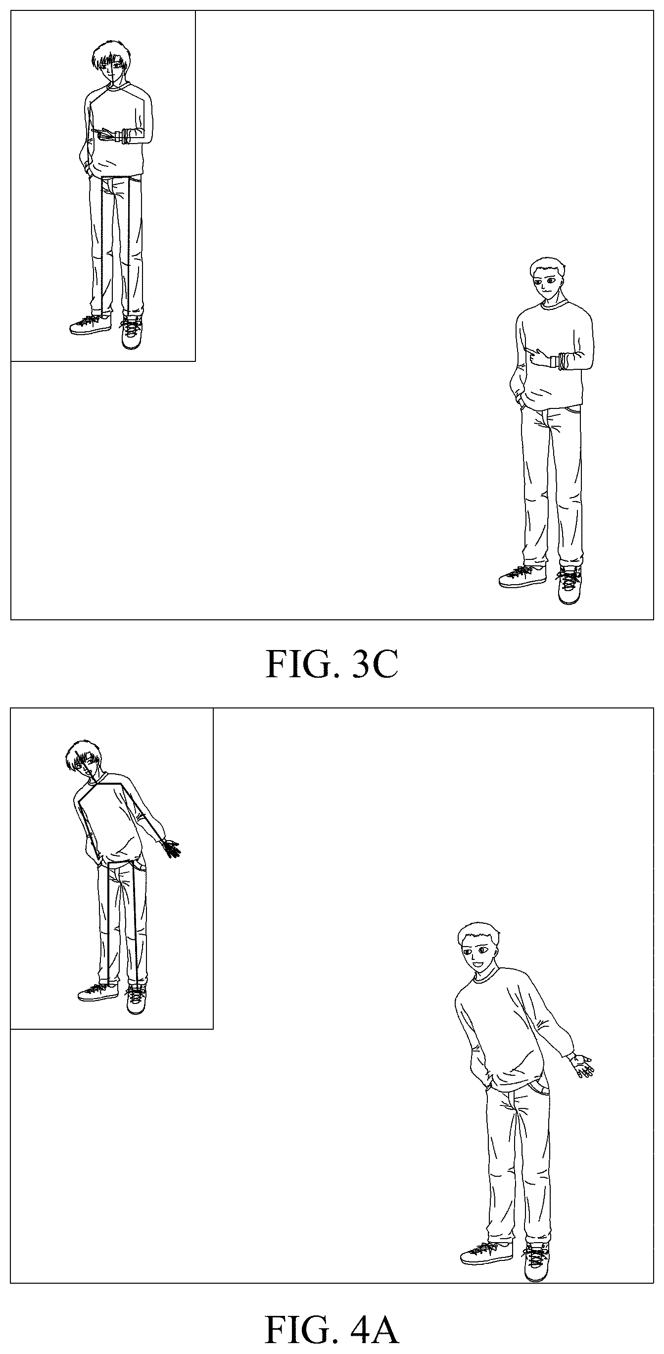
[0029] FIGS. 4A to 4C are schematic diagrams of simulating a change in a captured user's torso movement by a controlled model provided by the embodiments.
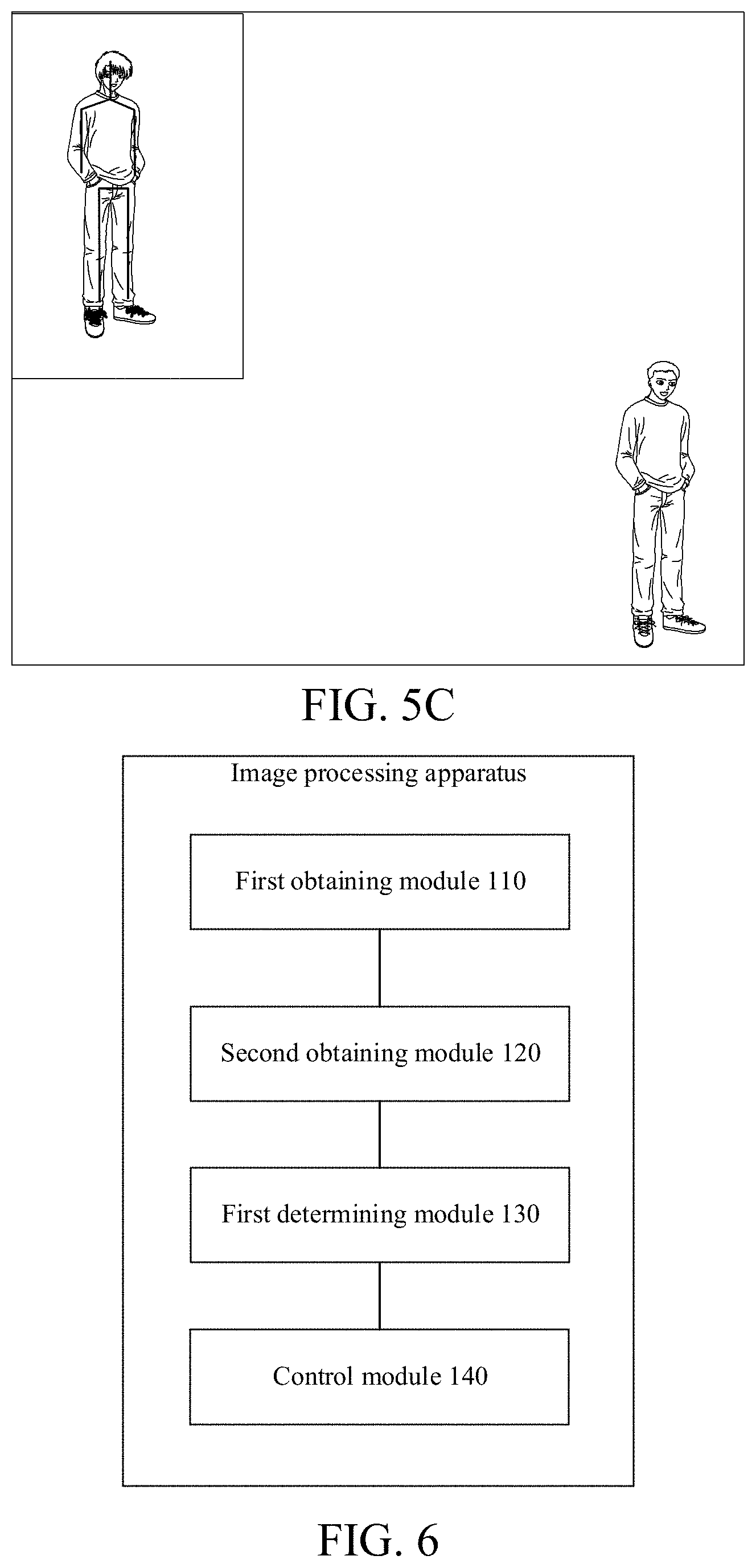
[0030] FIGS. 5A to 5C are schematic diagrams of simulating a captured user's foot movement by a controlled model provided by the embodiments.
[0031] FIG. 6 is a schematic structural diagram of an image processing apparatus provided by embodiments of the present disclosure.
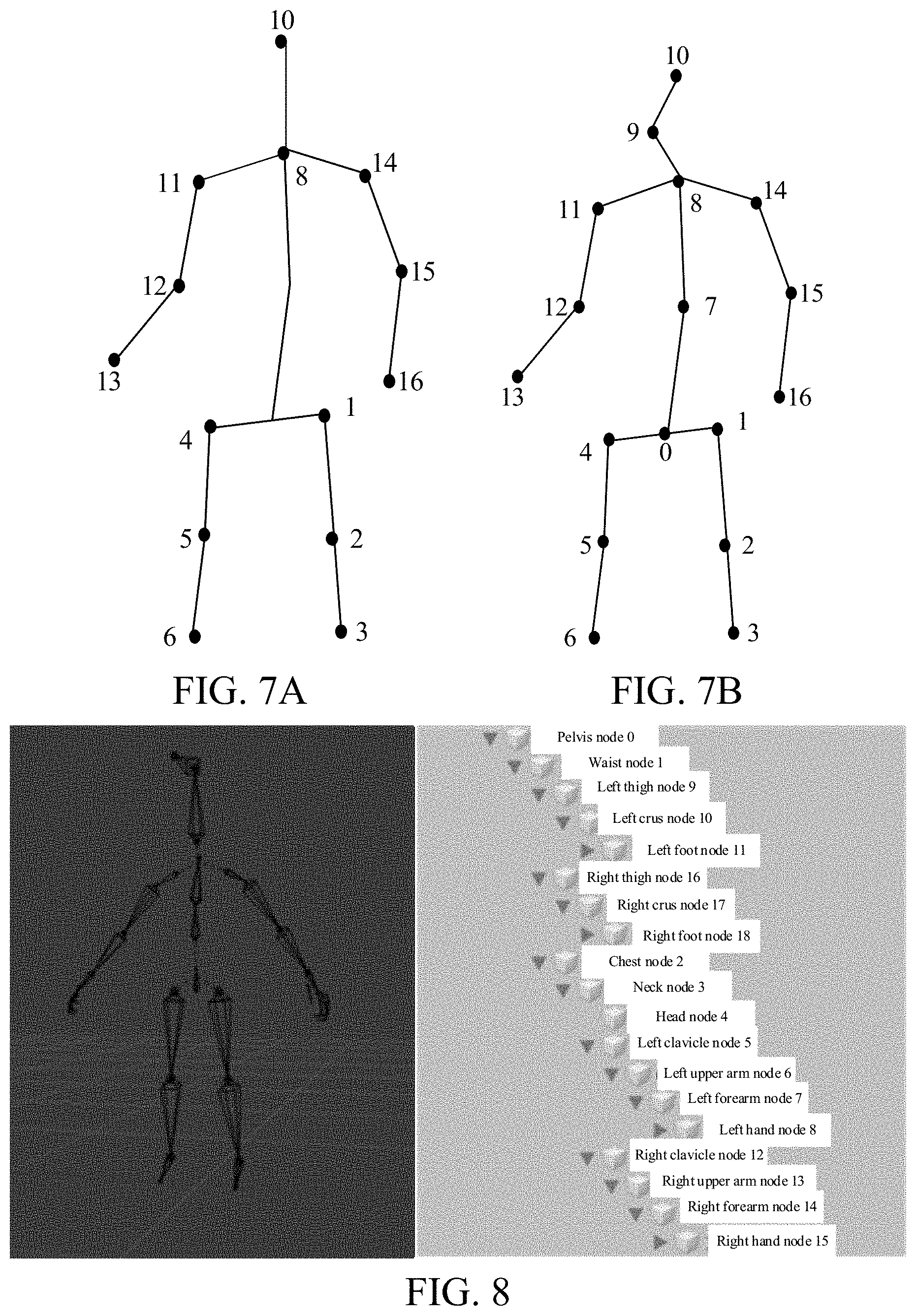
[0032] FIG. 7A is a schematic diagram of skeleton key points provided by embodiments of the present disclosure.
[0033] FIG. 7B is a schematic diagram of skeleton key points provided by other embodiments of the present disclosure.
[0034] FIG. 8 is a schematic diagram of a skeleton provided by embodiments of the present disclosure.
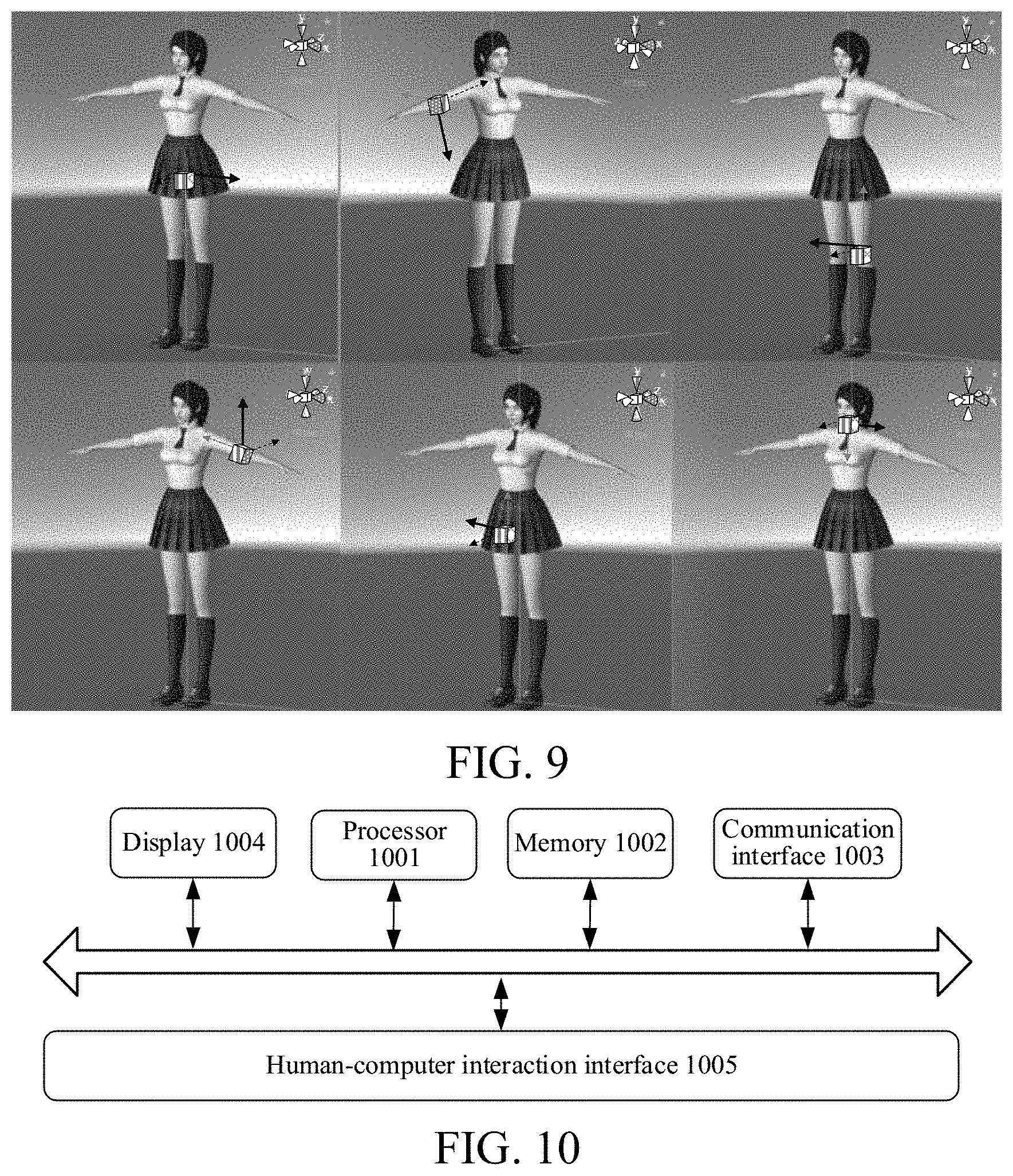
[0035] FIG. 9 is a schematic diagram of local coordinate systems of different bones of a human body provided by embodiments of the present disclosure.
[0036] FIG. 10 is a schematic structural diagram of an image device provided by embodiments of the present disclosure.
DETAILED DESCRIPTION
[0037] The technical solutions of the present disclosure are further described in detail below with reference to the accompanying drawings and specific embodiments.
[0038] As shown in FIG. 1, the embodiments provide an image processing method, including the following steps.
[0039] At step S110, an image is obtained.
[0040] At step S120, a feature of a part of a target is obtained based on the image
[0041] At step S130, movement information of the part is determined based on the feature.
[0042] At step S140, the movement of a corresponding part in a controlled model is controlled according to the movement information.
[0043] According to the image processing method provided by the embodiments, the movement of the controlled model may be driven by means of image processing.
[0044] The image processing method provided by the embodiments may be applied to an image device, where the image device may be various electronic devices that are capable of performing image device processing, such as an electronic device that performs image capture, image display, and image pixel recombination to generate an image. The image device includes, but is not limited to, various terminal devices, such as a mobile device and/or a fixed terminal, and further includes various image servers that are capable of providing an image service. The mobile terminal includes a portable device such as a mobile phone or a tablet computer a user may easily carry, and further includes a device worn by the user, such as a smart bracelet, a smart watch, or smart glasses. The fixed terminal includes a fixed desktop computer, etc.
[0045] In the embodiments, the image obtained in step S110 may be a two-dimensional (2D) or a three-dimensional (3D) image. The 2D image may include an image captured by a monocular or multi-ocular camera, such as a red-green-blue (RGB) image.
[0046] The 3D image may be a 3D image obtained based on 2D coordinates detected from a 2D image, and then using a conversion algorithm of the 2D coordinates to 3D coordinates. The 3D image may further be an image captured by a 3D camera.
[0047] An approach for obtaining the image may include: capturing the image using a camera of the image device; and/or, receiving the image from an external device; and/or, reading the image from a local database or a local memory.
[0048] In one example, step S120 includes: detecting the image to obtain a feature of one part of a target, where the part is any part on the target.
[0049] In another example, step S120 includes: detecting the image to obtain features of at least two parts of the target, where the two parts are different parts on the target. The two parts are continuously distributed on the target or are distributed on the target at an interval.
[0050] For example, if the target is a person, the any part includes any one of the following parts: head, torso, four limbs, upper limbs, lower limbs, hands, feet, etc. The at least two parts include at least two of the following parts: head, torso, four limbs, upper limbs, lower limbs, hands, feet, etc. In some other embodiments, the target is not limited to a human, but may also be various movable living bodies or non-living bodies such as animals
[0051] In the embodiments, a feature of one or more parts is obtained, where the feature may be a feature that represents spatial structure information, position information, or movement status of the part in various forms. In the embodiments, the image may be detected using a deep learning model such as a neural network so as to obtain the feature.
[0052] In one example, the feature represents a relative positional relationship between joint points in a human skeleton. In another example, the feature represents a positional change relationship of corresponding joint points in a human skeleton at adjacent time points, or the feature represents a positional change relationship of corresponding joint points in a human skeleton of a current picture and an initial coordinate system (also referred to as a camera coordinate system). More specifically, the feature includes 3D coordinates of joint points in a human skeleton detected by the deep learning model (such as a neural network used in an OpenPose project) in a world coordinate system. In still another example, the feature includes an optical flow feature that represents a change in a human posture, etc.
[0053] In step S110, the obtained image may be a frame of image or multiple frames of images. For example, when the obtained image is a frame of image, the subsequently obtained movement information reflects the movement of a joint point in a current image with respect to a corresponding joint point in the camera coordinate system. For another example, when multiple frames of images are obtained, the subsequently obtained movement information reflects the movement of a joint point in the current image with respect to a corresponding joint point in previous several frames of images, or the subsequently obtained movement information also reflects the movement of a joint point in the current image with respect to a corresponding joint point in the camera coordinate system. The number of obtained images is not limited in the present application.
[0054] After the feature is obtained, movement information of the part is obtained, where the movement information represents an action change of the corresponding part and/or an expression change caused by the action change, etc.
[0055] In one example, assuming that the two parts involved in S120 are the head and the torso, in step S140, a part in the controlled model corresponding to the head is controlled to move, and a part in the controlled model corresponding to the torso is controlled to move.
[0056] The movement information includes, but is not limited to, coordinates of a key point corresponding to the part, where the coordinates include, but are not limited to, 2D coordinates and 3D coordinates. The coordinates represent a change in the key point corresponding to the part with respect to a reference position, so as to represent the movement status of the corresponding part. The movement information may be expressed in various information forms such as a vector, an array, a one-dimensional value, and a matrix.
[0057] The controlled model may be a model corresponding to the target. For example, if the target is a person, the controlled model is a human model; if the target is an animal, the controlled model is a body model of the corresponding animal; and if the target is a transportation tool, the controlled model is a model of the transportation tool.
[0058] In the embodiments, the controlled model is a model for the category to which the target belongs. The model may be predetermined and may be further divided into multiple styles. The style of the controlled model may be determined based on a user instruction, and the controlled model may include multiple styles, such as a real-person style that simulates a real person, a comics and animation style, a network celebrity style, styles with different temperaments, and a game style. The styles with different temperaments may be literary style or a rock style. In the game style, the controlled model may be a character in the game.
[0059] For example, in the process of online teaching, some teachers are not willing to expose their face and body, thinking that this is privacy. If a video is directly recorded, the teacher's face and body are inevitably exposed. In the embodiments, an image of the movement of the teacher may be obtained by means of image capture, etc., and then a virtual controlled model movement is controlled by means of feature extraction and obtaining of movement information. In this way, on the one hand, the controlled model may simulate the movement of the teacher to complete body movement teaching through its own body movement, and on the other hand, the movement of the controlled model is used for teaching, the teacher's face and body are not directly exposed to the teaching video, and thus the privacy of the teacher is protected.
[0060] For another example, in a road surface surveillance video, if a video of a vehicle is directly captured, once the video is exposed to the network, all vehicle information of some specific users are exposed, but if surveillance is not performed, there may be a case where the responsibility cannot be determined when a traffic accident occurs. If the method according to the embodiments is used, a real vehicle movement is simulated with a vehicle model to obtain a surveillance video, license plate information of a vehicle and/or the overall outer contour of the vehicle is retained in the surveillance video, and the brand, model, color, ageing condition, etc. of the vehicle may be hidden, thereby protecting user privacy.
[0061] In some embodiments, as shown in FIG. 2, step S120 includes the following steps.
[0062] At step S121, a first-type feature of a first-type part of the target is obtained based on the image.
[0063] At step S122, a second-type feature of a second-type part of the target is obtained based on the image.
[0064] In the embodiments, the first-type feature and the second-type feature are features that represent spatial structure information, position information, and/or movement status of the corresponding part.
[0065] Different types of features have different characteristics, and applying to different types of parts may have higher precision. For example, in terms of a muscle movement of a human face with respect to the movement of four limbs, the precision of a spatial change caused by different features to the movement is different. In this case, in the embodiments, for the face and the four limbs, different types of features with the precision respectively adapted to the human face or the four limbs may be used for representation.
[0066] In some embodiments, for example, a first-type feature of a first-type part and a second-type feature of a second-type part are respectively obtained based on the image.
[0067] The first-type part and the second-type part are different types of parts; and different types of parts may be distinguished by the amplitudes of movement of different types of parts or distinguished using movement fineness of different types of parts.
[0068] In the embodiments, the first-type part and the second-type part may be two types of parts with a relatively large difference in the maximum amplitude of movement. The first-type part may be the head. The five sense organs of the head may move, but the amplitudes of movement of the five sense organs of the head are relatively small. The whole head may also move, for example, nodding or shaking, but the amplitude of movement is relatively small compared to the amplitude of movement of the limb or torso.
[0069] The second-type part may be upper limbs, lower limbs, or four limbs, and the amplitude of the limb movement is very large. If the movement statuses of the two types of parts are represented by the same feature, it may cause problems such as a decrease in precision or an increase in the complexity of an algorithm because of the amplitude of movement of a certain part.
[0070] Herein, according to the characteristics of different types of parts, the movement information is obtained with different types of features. Compared with the related approach of using the same type of features to represent the same type of parts, the precision of information of at least one type of part may be increased and the precision of the movement information may be improved.
[0071] In some embodiments, the obtaining subjects of the first-type feature and the second-type feature are different, for example, using different deep learning models or deep learning modules. The obtaining logic of the first-type feature is different from that of the second-type feature.
[0072] In some embodiments, step S121 includes: obtaining an expression feature of a head based on the image.
[0073] In the embodiments, the first-type part is a head, the head includes a face, and the expression feature includes, but is not limited to, at least one of the following: eyebrow movement, mouth movement, nose movement, eye movement, or cheek movement. The eyebrow movement may include: raising eyebrows and drooping eyebrows. The mouth movement may include: opening the mouth, closing the mouth, twitching the mouth, pouting, grinning, baring teeth, etc. The nose movement may include: the contraction of the nose caused by inhaling into the nose, and outward-blowing accompanying nose extension movement. The eye movement may include, but is not limited to: orbital movement and/or eyeball movement. The orbital movement may change the size and/or shape of the orbit, for example, the shape and size of the orbit may change during squinting, glaring, and smiling of eyes. The eyeball movement may include: the position of the eyeball in the orbit, for example, the change in the user's line of sight may cause the eyeball to be located at different positions of the orbit, the movement of the eyeballs of the left and right eyes together may reflect different emotional states of the user, etc. For the cheek movement, dimples or pear vortexes are produced when some users smile, and the shape of the cheek also changes accordingly.
[0074] In some embodiments, the head movement is not limited to the expression movement, and then the first-type feature is not limited to the expression feature and also includes: hair movement features of movement of hair of the head, etc.; and the first-type feature may further include: overall head movement features of shaking the head and/or nodding the head, etc.
[0075] In some embodiments, step S121 further includes: obtaining an intensity coefficient of the expression feature based on the image.
[0076] In the embodiments, the intensity coefficient may correspond to the expression amplitude of a facial expression. For example, multiple expression bases are set on the face, and one expression base corresponds to one expression action. The intensity coefficient herein may be used for representing the strength of the expression action, for example, the strength is the amplitude of the expression action.
[0077] In some embodiments, the greater the intensity coefficient is, the higher the strength represented is. For example, the higher the intensity coefficient is, the greater the amplitude of the mouth-opening expression base is, and the greater the amplitude of the pouting expression base is. For another example, the greater the intensity coefficient is, the higher the eyebrow-raising height for the eyebrow-raising expression base is.
[0078] By introducing the intensity coefficient, not only the controlled model may simulate the current action of the target, but also the strength of the current expression of the target may be precisely simulated, so as to achieve precise migration of expression. In this way, if the method is applied to a motion-sensing game scenario, the controlled object is a game character. By using this method, the game character not only may be controlled by the body movement of the user, but also may precisely simulate the expression features of the user. In this way, in the game scenario, the degree of simulation of the game scenario is increased, and the user's game experience is improved.
[0079] In the embodiments, when the target is a person, mesh information representing the expression change of the head is obtained by means of mesh detection, etc., and the change in the controlled model is controlled based on the mesh information. The mesh information includes, but is not limited to: quadrilateral mesh information and/or triangle patch information. The quadrilateral mesh information indicates information of longitude and latitude lines, and the triangle patch information is information of a triangle patch formed by connecting three key points.
[0080] For example, the mesh information is formed by a predetermined number of face key points including a face body surface, the intersection point of the longitude and latitude lines in the mesh represented by the quadrilateral mesh information may be the position of the face key points, and the change in the position of the intersection point of the mesh is the expression change. In this way, the expression feature and intensity coefficient obtained based on the quadrilateral mesh information may be used for precisely controlling the expression of the face of the controlled model. For another example, the vertices of a triangle patch corresponding to the triangle patch information include face key points, and the change in the position of the key points is the expression change. The expression feature and intensity coefficient obtained based on the triangle patch information may be used for precise control of the facial expression of the controlled model.
[0081] In some embodiments, obtaining the intensity coefficient of the expression feature includes: obtaining, based on the image, an intensity coefficient that represents each sub-part in the first-type part.
[0082] For example, the five sense organs of the face, i.e., eyes, eyebrows, nose, mouth, and ears, respectively correspond to at least one expression base, and some correspond to multiple expression bases, and one expression base corresponds to a type of expression action of a sense organ, while the intensity coefficient represents the amplitude of the expression action.
[0083] In some embodiments, step S130 includes: determining movement information of the head based on the expression feature and the intensity coefficient; and step S140 includes: controlling an expression change of a corresponding head in the controlled model according to the movement information of the head.
[0084] In some embodiments, step S122 includes: obtaining position information of a key point of the second-type part of the target based on the image.
[0085] The position information may be represented by position information of key points of the target, and the key points include: support key points and outer contour key points. If a person is taken as an example, the support key points include skeleton key points of a human body, and the contour key points may be key points of an outer contour of a human body surface. The number of key points is not limited in the present application, but the key points represent at least a portion of the skeleton.
[0086] The position information may be represented by coordinates, e.g., represented by 2D coordinates and/or 3D coordinates in the predetermined coordinate system. The predetermined coordinate system includes, but is not limited to, an image coordinate system where an image is located. The position information may be the coordinates of key points, and is obviously different from the foregoing mesh information. Because the second-type part is different from the first-type part, the change in the movement of the second-type part may be more precisely represented by using the position information.
[0087] In some embodiments, step S130 includes: determining movement information of the second-type part based on the position information.
[0088] If the target being a person is taken as an example, the second-type part includes, but is not limited to: a torso and/or four limbs; and a torso and/or upper limbs, and a torso and/or lower limbs.
[0089] Furthermore, step S122 specifically includes: obtaining a first coordinate of a support key point of the second-type part of the target based on the image; and obtaining a second coordinate based on the first coordinate.
[0090] The first coordinate and the second coordinate are both coordinates that represent the support key point. If the target being a person or an animal is taken as an example, the support key point herein is a skeleton key point.
[0091] The first coordinate and the second coordinate may be different types of coordinates. For example, the first coordinate is a 2D coordinate in the 2D coordinate system, and the second coordinate is a 3D coordinate in the 3D coordinate system. The first coordinate and the second coordinate may also be the same type of coordinates. For example, the second coordinate is a coordinate after the first coordinate is corrected, and in this case, the first coordinate and the second coordinate are the same type of coordinates. For example, the first coordinate and the second coordinate are 3D coordinates or 2D coordinates.
[0092] In some embodiments, obtaining the first coordinate of the support key point of the second-type part of the target based on the image includes: obtaining a first 2D coordinate of the support key point of the second-type part based on a 2D image; and obtaining the second coordinate based on the first coordinate includes: obtaining a first 3D coordinate corresponding to the first 2D coordinate based on the first 2D coordinate and a conversion relationship between a 2D coordinate and a 3D coordinate.
[0093] In some embodiments, obtaining the first coordinate of the support key point of the second-type part of the target based on the image includes: obtaining a second 3D coordinate of the support key point of the second-type part of the target based on a 3D image; and obtaining the second coordinate based on the first coordinate includes: obtaining a third 3D coordinate based on the second 3D coordinate.
[0094] For example, the 3D image directly obtained in step S110 includes: a 2D image and a depth image corresponding to the 2D image. The 2D image may provide coordinate values of the support key point in a xoy plane, and the depth value in the depth image may provide coordinates of the support key point on a z axis. The z axis is perpendicular to the xoy plane.
[0095] In some embodiments, obtaining the third 3D coordinate based on the second 3D coordinate includes: correcting, based on the second 3D coordinate, a 3D coordinate of a support key point corresponding to an occluded portion of the second-type part in the 3D image so as to obtain the third 3D coordinate.
[0096] In the embodiments, the second 3D coordinate is first extracted from the 3D image using a 3D model, and then the blocking of different parts in the target is considered. Through correction, correct third 3D coordinates of different parts of the target in a 3D space may be obtained, thereby ensuring subsequent control precision of the controlled model.
[0097] In some embodiments, step S130 includes: determining a quaternion of the second-type part based on the position information.
[0098] For a specific method for determining the quaternion based on the position information, please refer to the subsequent description in Example 3.
[0099] In some embodiments, the movement information is not only represented by the quaternion, but also represented by coordinate values in different coordinate systems; for example, coordinate values in an Eulerian coordinate system or a Lagrangian coordinate system, etc. By using the quaternion, the spatial position and/or rotation in different directions of the second-type part may be precisely described.
[0100] In some embodiments, the quaternion is taken as the movement information. In specific implementation, it is not limited to the quaternion, but may also be indicated by coordinate values in various coordinate systems with respect to a reference point, for example, the quaternion may be replaced with the Eulerian coordinates or Lagrangian coordinates.
[0101] In some embodiments, step S120 includes: obtaining first position information of the support key point of a first part in the second-type part; and obtaining second position information of the support key point of a second part in the second-type part.
[0102] The second-type part may include at least two different parts. Thus, the controlled model may simultaneously simulate the movement of at least two parts of the target.
[0103] In some embodiments, step S130 includes: determining movement information of the first part according to the first position information; and determining movement information of the second part according to the second position information.
[0104] In some embodiments, step S140 includes: controlling movement of a part in the controlled model corresponding to the first part according to the movement information of the first part; and controlling movement of a part in the controlled model corresponding to the second part according to the movement information of the second part.
[0105] In some other embodiments, the first part is a torso; and the second part is upper limbs, lower limbs, or four limbs.
[0106] In some embodiments, the method further includes: determining a second type of movement information of a connecting portion according to features of the at least two parts and a first movement constraint condition of the connecting portion, where the connecting portion is used for connecting the two parts; and controlling movement of the connecting portion of the controlled model according to the second type of movement information.
[0107] In some embodiments, movement information of some parts is obtained separately by means of the movement information obtaining model, and the movement information obtained in this way is referred to as a first type of movement information. Moreover, some parts are connecting portions for connecting other two or more parts, and the movement information of these connecting portions is referred to as the second type of movement information in the embodiments for convenience. The second type of movement information herein is also one of information that represents the movement status of the part in the target. In some embodiments, the second type of movement information is determined based on the first type of movement information of the two parts connected by the connecting portion.
[0108] Therefore, the second type of movement information differs from the first type of movement information in that: the second type of movement information is the movement information of the connecting portion, while the first type of movement information is movement information of parts other than the connecting portion; and the first type of movement information is generated separately based on the movement status of the corresponding part, and the second type of movement information may be related to the movement information of other parts connected to the corresponding connecting portion.
[0109] In some embodiments, step S140 includes: determining a control mode for controlling the connecting portion according to the type of the connecting portion; and controlling the movement of the connecting portion of the controlled model according to the control mode and the second type of movement information.
[0110] The connecting portion may be used for connecting the other two parts, for example, taking a person as an example, the neck, a wrist, an ankle, and a waist are all connecting portions for connecting the two parts.
[0111] The movement information of these connecting portions may be inconvenient to detect or depend on other adjacent parts to a certain extent. Therefore, in the embodiments, the movement information of the connecting portion may be determined according to the first type of movement information of the two or more other parts connected to the connecting portion, so as to obtain the second type of movement information of the corresponding connecting portion.
[0112] In the embodiments, considering special information such as an approach for obtaining the movement information of the connecting portion and the constraint condition, a corresponding control mode is determined according to the type of the connecting portion, so as to achieve precise control of the corresponding connecting portion in the controlled model.
[0113] For example, the lateral rotation of the wrist, for example, the rotation by taking the direction in which an upper arm extends to the hand as an axis, is caused by the rotation of the upper arm.
[0114] For another example, the lateral rotation of the ankle, for example, the rotation by taking the extension direction of the crus as an axis, is also directly driven by the crus. Certainly, it is also possible that the crus is driven by the thigh, and the ankle is further driven by the crus.
[0115] Moreover, for the connecting portion, the neck, its rotation determines the orientation of the face and the orientation of the torso.
[0116] In some other embodiments, determining the control mode for controlling the connecting portion according to the type of the connecting portion includes: if the connecting portion is a first type of connecting portion, determining to use a first type of control mode, where the first type of control mode is used for directly controlling the movement of the connecting portion corresponding to the first type of connecting portion in the controlled model.
[0117] In some embodiments, the first type of connecting portion is driven by its rotation but not driven by the other parts.
[0118] In some other embodiments, the connecting portion further includes a second type of connecting portion other than the first type of connecting portion. The movement of the second type of connecting portion herein may not be limited to itself, but driven by the other parts.
[0119] In some embodiments, determining the control mode for controlling the connecting portion according to the type of the connecting portion includes: if the connecting portion is a second type of connecting portion, determining to use a second type of control mode, where the second type of control mode is used for indirectly controlling the movement of the second type of connecting portion by controlling the parts other than the second type of connecting portion of the controlled model.
[0120] The parts other than the second type of connecting portion include, but are not limited to: a part directly connected to the second type of connecting portion, or a part indirectly connected to the second type of connecting portion.
[0121] For example, when the wrist is rotated laterally, it may be that the entire upper limb is moving, and then a shoulder and an elbow are rotating, so that the rotation of the wrist may be indirectly driven by controlling the lateral rotation of the shoulder and/or the elbow.
[0122] In some embodiments, controlling the movement of the connecting portion of the controlled model according to the control mode and the second type of movement information includes: if the control mode is the second type of control mode, splitting the second type of movement information to obtain a first type of rotation information of the connecting portion, the rotation of which is caused by a pull portion; adjusting movement information of the pull portion according to the first type of rotation information; and controlling the movement of the pull portion in the controlled model by using the adjusted movement information of the pull portion so as to indirectly control the movement of the connecting portion.
[0123] In the embodiments, the first type of rotation information is not rotation information generated by the movement of the second type of connecting portion, but movement information of the second type of connecting portion generated with respect to a specific reference point (e.g. the center of the human body) of the target when the second type of connecting portion is pulled by the movement of the other parts (i.e., the pull portion) connected to the second type of connecting portion.
[0124] In the embodiments, the pull portion is a part directly connected to the second type of connecting portion. Taking the wrist being the second type of connecting portion as an example, the pull portion is the elbow above the wrist or even the shoulder. Taking the ankle being the second type of connecting portion is taken as an example, the pull portion is the knee above the ankle or even the root of the thigh.
[0125] The lateral rotation of the wrist along the straight direction from the shoulder to the elbow and to the wrist may be a rotation caused by the shoulder or the elbow, and when the movement information is detected, it is caused by the movement of the wrist. Thus, the lateral rotation information of the wrist essentially should be assigned to the elbow or the shoulder. By means of such transfer assignment, the movement information of the elbow or the shoulder is adjusted, and the adjusted movement information is used to control the movement of the elbow or the shoulder of the controlled model. Thus, the lateral rotation corresponding to the elbow or the shoulder, as seen from the effect bar of the image, is reflected by the wrist of the controlled model, so that the movement of the target is precisely simulated by the controlled model.
[0126] In some embodiments, the method further includes: splitting the second type of movement information to obtain a second type of rotation information of the rotation of the second type of connecting portion with respect to the pull portion; and controlling the rotation of the connecting portion with respect to the pull portion in the controlled model by using the second type of rotation information.
[0127] The first type of rotation information is information obtained by an information model that extracts the rotation information directly according to the features of the image, and the second type of rotation information is rotation information obtained by adjusting the first type of rotation information. In the embodiments, first of all, the movement information of the second type of connecting portion with respect to a predetermined posture may be known through the features of the second type of connecting portion, for example, the 2D coordinates or the 3D coordinates, and the movement information is referred to as the second type of movement information. The second type of movement information includes, but is not limited to, rotation information.
[0128] In some embodiments, the second type of connecting portion includes: a wrist and an ankle.
[0129] In some other embodiments, if the second type of connecting portion is the wrist, the pull portion corresponding to the wrist includes: a forearm and/or an upper arm; and/or if the second type of connecting portion is the ankle, the pull portion corresponding to the ankle includes: a crus and/or a thigh.
[0130] In some embodiments, the first type of connecting portion includes a neck connecting the head and the torso.
[0131] In still some embodiments, determining the movement information of the connecting portion according to the features of the at least two parts and the first movement constraint condition of the connecting portion includes: determining orientation information of the at least two parts according to the features of the at least two parts; determining alternative orientation information of the connecting portion according to the orientation information of the at least two parts; and determining the movement information of the connecting portion according to the alternative orientation information and the first movement constraint condition.
[0132] In some embodiments, determining the alternative orientation information of the connecting portion according to the orientation information of the at least two parts includes: determining a first alternative orientation and a second alternative orientation of the connecting portion according to the orientation information of the at least two parts.
[0133] Two included angles may be formed between the orientation information of the two parts, and the two included angles correspond to the rotation information of different orientations of the connecting portion. Therefore, the orientations respectively corresponding to the two included angles are alternative orientations. Only one of the two alternative orientations satisfies the first movement constraint condition of the movement of the connecting portion, and therefore, the second type of movement information needs to be determined according to a target orientation of the first movement constraint condition. In the embodiments, the included angle of rotation satisfying the first movement constraint condition is taken as the second type of movement information.
[0134] For example, two included angles are formed between the orientation of the face and the orientation of the torso, and the sum of the two included angles is 180 degrees. It is assumed that the two included angles are a first included angle and a second included angle, respectively. Moreover, the first movement constraint condition for the neck connecting the face and the torso is between -90 degrees and 90 degrees, and then angles exceeding 90 degrees are excluded according to the first movement constraint condition. In this way, abnormalities that the rotation angle exceeds 90 degrees clockwise or counterclockwise, e.g., 120 degrees and 180 degrees, may be reduced in the process that the controlled model simulates the movement of the target. If the first movement constraint condition is between -90 degrees and 90 degrees, the first movement constraint condition corresponds to two extreme angles. One is -90 degrees and the other is 90 degrees.
[0135] However, if the rotation angle exceeds the range of -90 degrees to 90 degrees, the detected rotation angle is modified as the maximum angle defined by the first movement constraint condition. For example, if a rotation angle exceeding 90 degrees is detected, the detected rotation angle is modified as an extreme angle closer to the detected rotation angle, for example, 90 degrees.
[0136] In some embodiments, determining the movement information of the connecting portion according to the alternative orientation information and the first movement constraint condition includes: selecting target orientation information within an orientation change constraint range from the first alternative orientation information and the second alternative orientation information; and determining the movement information of the connecting portion according to the target orientation information.
[0137] For example, taking the neck as an example, the face faces right, and then the corresponding orientation of the neck may be 90 degrees rightward or 270 degrees leftward. However, according to the physiological structure of the human body, the orientation of the neck of the human body may not be changed by rotating 270 degrees leftward so that the neck faces right. In this case, the orientation of the neck, rightward 90 degrees and leftward 270 degrees, are both the alternative orientation information, the orientation information of the neck needs to be further determined, and needs to be determined according to the foregoing first movement constraint condition. In this example, the rightward 90 degrees of the neck is the target orientation information of the neck, and according to the rightward 90 degrees of the neck, the second type of movement information of the neck with respect to the camera coordinate system is rotating 90 degrees rightward.
[0138] The target orientation information herein is information that satisfies the first movement constraint condition.
[0139] In some embodiments, determining the orientation information of the at least two parts according to the features of the at least two parts includes: obtaining a first key point and a second key point of each of the at least two parts; obtaining a first reference point of each of the at least two parts, where the first reference point is a predetermined key point within the target; generating a first vector based on the first key point and the first reference point, and generating a second vector based on the second key point and the first reference point; and determining orientation information of each of the at least two parts based on the first vector and the second vector.
[0140] If the first part in the two parts is the shoulder of the human body, the first reference point of the first part is a waist key point of the target or a midpoint of key points of two hips. If the second part in the two parts is the face, the first reference point of the second part is a connecting point of the neck connected to the face and the shoulder.
[0141] The first reference point and the corresponding two key points are connected to form two vectors, and then the two vectors are cross-multiplied to obtain a normal vector of the two vectors. The direction of the normal vector may be regarded as the orientation of the corresponding part. Therefore, in some embodiments, determining the orientation information of each of the at least two parts based on the two vectors includes: cross-multiplying the first vector and the second vector of one part to obtain the normal vector of a plane where the corresponding part is located; and taking the normal vector as the orientation information of the part.
[0142] If the normal vector is determined, the orientation of the plane where the part is located is also determined.
[0143] In some embodiments, determining the movement information of the connecting portion based on the movement information of the at least two parts includes: obtaining a fourth 3D coordinate of the connecting portion with respect to a second reference point; and obtaining absolute rotation information of the connecting portion according to the fourth 3D coordinate; and controlling the movement of the corresponding part in the controlled model according to the movement information includes: controlling the movement of the corresponding connecting portion of the controlled model based on the absolute rotation information.
[0144] In some embodiments, the second reference point may be one of the support key points of the target, and taking the target being a person as an example, the second reference point may be a key point of the parts connected by the first type of connecting portion. For example, taking the neck as an example, the second reference point may be a key point of the shoulder connected to the neck.
[0145] In some other embodiments, the second reference point may be the same as the first reference point, for example, the first reference point and the second reference point both may be root nodes of the human body, and the root node of the human body may be a midpoint of a connecting line of two key points of the hips of the human body. The root node includes, but is not limited to, a key point 0 shown in FIG. 7B. FIG. 7B is a schematic diagram of the skeleton of the human body. In FIG. 7B, a total of 17 skeleton joint points with labels 0 to 16 are included.
[0146] In some other embodiments, controlling the movement of the corresponding connecting portion of the controlled model based on the absolute rotation information further includes: splitting the absolute rotation information according to a pull hierarchical relationship between the multiple connecting portions in the target to obtain relative rotation information; and controlling the movement of the corresponding connecting portion in the controlled model based on the relative rotation information.
[0147] For example, the following is an example of one hierarchical relationship: the first level: pelvis; the second level: waist; the third level: thighs (e.g., left thigh and right thigh); the fourth level: caves (e.g., left crus and right crus); and the fifth level: feet.
[0148] For another example, the following is another hierarchical relationship: the first level: chest; the second level: neck; and the third level: head.
[0149] Further, for example, the following is still another hierarchical relationship: the first level: clavicles, corresponding to the shoulder; the second level: upper arms; the third level: forearms (also referred to as lower arms); and the fourth level: hand.
[0150] From the first level to the fifth level, the hierarchical relationship decreases in sequence. The movement of the part at the upper level affects the movement of the part at the lower level. Therefore, the level of the pull portion is higher than that of the connecting portion.
[0151] During determination of the second type of movement information, first, the movement information of the key points corresponding to the part at each level is obtained, and then based on the hierarchical relationship, the movement information (i.e., the relative rotation information) of the key points of the part at the low level with respect to the key points of the part at the high level is determined.
[0152] For example, if a quaternion is used for representing movement information, the relative rotation information may be represented by the following calculation formula (1). A rotation quaternion of each key point with respect to a camera coordinate system is {Q.sub.0, Q.sub.1, . . . Q.sub.18}, and then a rotation quaternion q.sub.i of each key point with respect to a parent key point is calculated.
q.sub.i=Q.sub.parent(i).sup.-1.sub.rent(i)Q.sub.i (1)
[0153] where the parent key point parent(i) is a key point at the previous level of the current key point i. Q.sub.1 is a rotation quaternion of the current key point i with respect to the camera coordinate system, and Q.sub.parent(i).sup.-1 is an inverse rotation parameter of the key point at the previous level. For example, Q.sub.parent(i) is a rotation parameter of the key point at the previous level, and the rotation angle is 90 degrees; and then the rotation angle of Q.sub.parent(i).sup.-1 is -90 degrees.
[0154] In some embodiments, controlling the movement of the corresponding connecting portion of the controlled model based on the absolute rotation information further includes: correcting the relative rotation information according to a second constraint condition; and controlling the movement of the corresponding connecting portion in the controlled model based on the relative rotation information includes: controlling the movement of the corresponding connecting portion in the controlled model based on the corrected relative rotation information.
[0155] In some embodiments, the second constraint condition includes: a rotatable angle of the connecting portion.
[0156] In some embodiments, the method further includes: performing posture defect correction on the second type of movement information to obtain corrected second type of movement information; and controlling the movement of the connecting portion of the controlled model according to the second type of movement information includes: controlling the movement of the connecting portion of the controlled model by using the corrected second type of movement information.
[0157] For example, some users have a problem that the shape of the body is not very standard and a problem of uncoordinated walking, etc. In order to reduce the phenomena that the controlled model directly imitates relatively strange movements, etc. In the embodiments, posture defect correction may be performed on the second type of movement information to obtain the corrected second type of movement information.
[0158] In some embodiments, the method further includes: performing posture defect correction on the first type of movement information to obtain corrected first type of movement information. Step S140 includes: controlling the movement of the corresponding part in the controlled model by using the corrected first type of movement information.
[0159] In some embodiments, the posture defect correction includes at least one of the following: an ipsilateral defect of upper and lower limbs; a bowleg movement defect; a splayfoot movement defect; or a pigeon-toe movement defect.
[0160] In some embodiments, the method further includes: obtaining a posture defect correction parameter according to difference information between a body form of the target and a standard body form, where the posture defect correction parameter is used for correcting the first type of movement information or the second type of movement information.
[0161] For example, before controlling the controlled model using the image including the target, the body form of the target is detected first, and then the detected body form is compared with the standard body form to obtain difference information; and posture defect correction is performed by means of the difference information.
[0162] A prompt about maintaining a predetermined posture is output on a display interface, and a user maintains the predetermined posture after seeing the prompt, so that the image device may capture an image of the user maintaining the predetermined posture. Then, whether the predetermined posture maintained by the user is standard enough is determined by means of image detection to obtain the difference information. The predetermined posture may include, but is not limited to, an upright posture of the human body.
[0163] For example, some persons have splayfeet, while a normal standard standing posture should be that connecting lines between tiptoes and heels of the feet are parallel. After obtaining the first type of movement information and/or the second type of movement information corresponding to features of the target, such non-standard correction in the body form (i.e., the posture defect correction) is considered when the controlled model is controlled.
[0164] In some other embodiments, the method further includes: correcting a proportion of different parts of a standard model according to a proportional relationship between different parts of the target to obtain a corrected controlled model.
[0165] There may be differences in the proportional relationships between parts of different targets. For example, taking a person as an example, the proportion of the leg length to the head length of a professional model is greater than that of an ordinary person. Some persons have full buttocks, and then the distances between their hips may be greater than that of an ordinary person.
[0166] The standard model may be a mean value model obtained based on a large amount of human body data. In order to make the controlled model more precisely simulate the movement of the target, in the embodiments, the proportions of different parts of the standard model are corrected according to the proportional relationship between different parts of the target to obtain the corrected controlled model. For example, taking the target being a person as an example, the corrected parts include, but are not limited to, the hips and/or legs.
[0167] As shown in FIGS. 3A, 3B, and 3C, the small image in the upper left corner of the image is the captured image, and in the lower right corner is the controlled model of the human body. The user's hand moves. From FIG. 3A to FIG. 3B and then from FIG. 3B to FIG. 3C, the user's hand moves, and the hand of the controlled model also moves. The user's hand movement sequentially changes from first clenching to palm extension and then to index finger extension in FIGS. 3A to 3C, while the controlled model simulates the user's gesture to change from first clenching to palm extension and then to index finger extension.
[0168] As shown in FIGS. 4A, 4B, and 4C, the small image in the upper left corner of the image is a captured image, and in the lower right corner is the controlled model of the human body. The user's torso moves. From FIG. 4A to FIG. 4B and then from FIG. 4B to FIG. 4C, the user's torso moves, and the torso of the controlled model also moves. From FIGS. 4A to 4C, the user thrusts the hips toward the right of the image, thrusts the hips toward the left of the image, and finally stands upright. The controlled model also simulates the user's torso movement.
[0169] As shown in FIGS. 5A, 5B, and 5C, the small image in the upper left corner of the image is a captured image, and in the lower right corner is the controlled model of the human body. From FIGS. 5A to 5C, the user takes a step toward the right of the image, takes a step toward the left of the image, and finally stands up straight. The controlled model also simulates the user's foot movement.
[0170] In addition, in FIGS. 4A to 4C, the controlled model also simulates the user's expression change.
[0171] As shown in FIG. 6, the embodiments provide an image processing apparatus, including the following modules:
[0172] a first obtaining module 110, configured to obtain an image;
[0173] a second obtaining module 120, configured to obtain a feature of a part of a target based on the image;
[0174] a first determining module 130, configured to determine movement information of the part based on the feature; and
[0175] a control module 140, configured to control the movement of a corresponding part in a controlled model according to the movement information.
[0176] In some embodiments, the second obtaining module 120 is specifically configured to: obtain a first-type feature of a first-type part of the target based on the image; and/or obtain a second-type feature of a second-type part of the target based on the image.
[0177] In some embodiments, the second obtaining module 120 is specifically configured to obtain an expression feature of a head and an intensity coefficient of the expression feature based on the image.
[0178] In some embodiments, obtaining the intensity coefficient of the expression feature based on the image includes: obtaining, based on the image, an intensity coefficient that represents each sub-part in the first-type part.
[0179] In some embodiments, the first determining module 130 is specifically configured to determine the movement information of the head based on the expression feature and the intensity coefficient; and the control module 140 is specifically configured to control an expression change of a head in the controlled model according to the movement information of the head.
[0180] In some embodiments, the second obtaining module 120 is configured to obtain mesh information of the first-type part based on the image.
[0181] In some embodiments, the second obtaining module 120 is specifically configured to obtain, based on the image, an intensity coefficient that represents each sub-part in the first-type part.
[0182] In some embodiments, the second obtaining module 120 is specifically configured to obtain position information of a key point of the second-type part of the target based on the image; and the first determining module 130 is specifically configured to determine movement information of the second-type part based on the position information.
[0183] In some embodiments, the second obtaining module 120 is specifically configured to: obtain a first coordinate of a support key point of the second-type part of the target based on the image; and obtain a second coordinate based on the first coordinate.
[0184] In some embodiments, the second obtaining module 120 is specifically configured to obtain a first 2D coordinate of the support key point of the second-type part based on a 2D image; and obtain a first 3D coordinate corresponding to the first 2D coordinate based on the first 2D coordinate and a conversion relationship between a 2D coordinate and a 3D coordinate.
[0185] In some embodiments, the second obtaining module 120 is specifically configured to obtain a second 3D coordinate of the support key point of the second-type part of the target based on a 3D image; and obtain a third 3D coordinate based on the second 3D coordinate.
[0186] In some embodiments, the second obtaining module 120 is specifically configured to correct, based on the second 3D coordinate, a 3D coordinate of a support key point corresponding to an occluded portion of the second-type part in the 3D image so as to obtain the third 3D coordinate.
[0187] In some embodiments, the first determining module 130 is specifically configured to determine a quaternion of the second-type part based on the position information.
[0188] In some embodiments, the second obtaining module 120 is specifically configured to: obtain first position information of the support key point of a first part in the second-type part; and obtain second position information of the support key point of a second part in the second-type part.
[0189] In some embodiments, the first determining module 130 is specifically configured to: determine movement information of the first part according to the first position information; and determine movement information of the second part according to the second position information.
[0190] In some embodiments, the control module 140 is specifically configured to: control movement of a part in the controlled model corresponding to the first part according to the movement information of the first part; and control movement of a part in the controlled model corresponding to the second part according to the movement information of the second part.
[0191] In some embodiments, the first part is a torso; and the second part is upper limbs, lower limbs, or four limbs.
[0192] Several specific examples are provided below with reference to any one of the foregoing embodiments.
Example 1
[0193] This example provides an image processing method, including the following steps.
[0194] An image is captured, where the image includes a target, and the target includes, but is not limited to, a human body.
[0195] Face key points of the human body are detected, where the face key points may be contour key points of a face surface.
[0196] Torso key points and/or limb key points of the human body are detected, where the torso key points and/or the limb key points herein may all be 3D key points and are represented by 3D coordinates. The 3D coordinates may be 3D coordinates obtained by detecting 2D coordinates from a 2D image and then using a conversion algorithm from the 2D coordinates to the 3D coordinates. The 3D coordinates may also be 3D coordinates extracted from a 3D image captured by a 3D camera. The limb key points herein may include upper limb key points and/or lower limb key points. Taking the hand as an example, hand key points of the upper limb key points include, but are not limited to, wrist joint key points, metacarpophalangeal joint key points, knuckle joint key points, and fingertip key points. The positions of these key points may reflect movements of the hand and fingers.
[0197] Mesh information of the face is generated according to the face key points. An expression base corresponding to the current expression of the target is selected according to the mesh information, and the expression of the controlled model is controlled according to the expression base; and the expression strength of the controlled model corresponding to each expression base is controlled according to an intensity coefficient reflected by the mesh information.
[0198] Quaternions are converted according to the torso key points and/or the limb key points. The torso movement of the controlled model is controlled according to quaternions corresponding to the torso key points; and/or the limb movement of the controlled model is controlled according to quaternions corresponding to the limb key points.
[0199] For example, the face key points may include 106 key points. The torso key points and/or the limb key points may include 14 key points or 17 key points, specifically as shown in FIG. 7A and FIG. 7B. FIG. 7A is a schematic diagram including 14 skeleton key points. FIG. 7B is a schematic diagram including 17 skeleton key points.
[0200] FIG. 7B may be a schematic diagram including 17 key points generated based on the 14 key points shown in FIG. 7A. The 17 key points in FIG. 7B are equivalent to the key points shown in FIG. 7A with the addition of key point 0, key point 7, and key point 9. The 2D coordinates of key point 9 may be preliminarily determined based on the 2D coordinates of key point 8 and key point 10, and the 2D coordinates of key point 7 may be determined according to the 2D coordinates of key point 8 and the 2D coordinates of key point 0. Key point 0 may be a reference point provided by the embodiments of the present disclosure, and the reference point may serve as the foregoing first reference point and/or second reference point.
[0201] In this example, the controlled model may be a game character in a game scenario, a teacher model in an online education video in an online teaching scenario, or a virtual anchor in a virtual webcasting scenario. In short, the controlled model is determined according to the application scenario. If the application scenario is different, the model and/or appearance of the controlled model is different.
[0202] For example, in a conventional platform teaching scenario, such as mathematics, physics, or the like, the clothes of the teacher model may be relatively formal, such as a suit. For another example, for a sports teaching scenario such as yoga or gymnastics, the clothes of the controlled model may be sportswear.
Example 2
[0203] This example provides an image processing method, including the following steps.
[0204] An image is captured, where the image includes a target, and the target includes, but is not limited to, a human body.
[0205] Torso key points and/or limb key points of the human body are detected, where the torso key points and/or the limb key points here may all be 3D key points and are represented by 3D coordinates. The 3D coordinates may be 3D coordinates obtained by detecting 2D coordinates from a 2D image and then using a conversion algorithm from the 2D coordinates to the 3D coordinates. The 3D coordinates may also be 3D coordinates extracted from a 3D image captured by a 3D camera. The limb key points herein may include upper limb key points and/or lower limb key points. Taking the hand as an example, hand key points of the upper limb key points include, but are not limited to, wrist joint key points, metacarpophalangeal joint key points, knuckle joint key points, and fingertip key points. The positions of these key points may reflect movements of the hand and fingers.
[0206] The torso key points are converted into quaternions that represent a torso movement. The quaternions may be referred to as torso quaternions. The limb key points are converted into quaternions that represent a limb movement. The quaternions may be referred to as limb quaternions.
[0207] The torso movement of the controlled model is controlled by the torso quaternions. The limb movement of the controlled model is controlled by the limb quaternions.
[0208] The torso key points and/or the limb key points may include 14 key points or 17 key points, specifically as shown in FIG. 7A or FIG. 7B.
[0209] In this example, the controlled model may be a game character in a game scenario, a teacher model in an online education video in an online teaching scenario, or a virtual anchor in a virtual webcasting scenario. In short, the controlled model is determined according to the application scenario. If the application scenario is different, the model and/or appearance of the controlled model is different.
[0210] For example, in a conventional platform teaching scenario, such as mathematics, physics, or the like, the clothes of the teacher model may be relatively formal, such as a suit. For another example, for a sports teaching scenario such as yoga or gymnastics, the clothes of the controlled model may be sportswear.
Example 3
[0211] This example provides an image processing method, including the following steps.
[0212] An image is obtained, where the image includes a target, and the target may be a human body.
[0213] A 3D posture of the target in a 3D space is obtained according to the image, where the 3D posture may be represented by 3D coordinates of skeleton key points of the human body.
[0214] An absolute rotation parameter of a joint of the human body in a camera coordinate system is obtained, where the absolute rotation position may be determined by coordinates in the camera coordinate system.
[0215] A coordinate direction of the joint is obtained according to the coordinates. A relative rotation parameter of the joint is determined according to a hierarchical relationship. Determining the relative parameter may specifically include: determining the position of a key point of the joint with respect to a root node of the human body. The relative rotation parameter may be represented by a quaternion. The hierarchical relationship herein may be a pull relationship between joints. For example, the movement of an elbow joint may drive the movement of a wrist joint to some extent, the movement of a shoulder joint may also drive the movement of the elbow joint, or the like. The hierarchical relationship may also be predetermined according to joints of the human body.
[0216] The rotation of the controlled model is controlled by the quaternion.
[0217] For example, the following is an example of one hierarchical relationship. The first level: pelvis; the second level: waist; the third level: thighs (e.g., left thigh and right thigh); the fourth level: caves (e.g., left crus and right crus); and the fifth level: feet.
[0218] For another example, the following is another hierarchical relationship. The first level: chest; the second level: neck; and the third level: head.
[0219] Further, for example, the following is still another hierarchical relationship. The first level: clavicles, corresponding to the shoulder; the second level: upper arms; the third level: forearms (also referred to as lower arms); and the fourth level: hand.
[0220] From the first level to the fifth level, the hierarchical relationship decreases in sequence. The movement of the part at the upper level affects the movement of the part at the lower level. Therefore, the level of the pull portion is higher than that of the connecting portion.
[0221] During determination of the second type of movement information, first, the movement information of the key points of the part at each level is obtained, and then based on the hierarchical relationship, the movement information (i.e., the relative rotation information) of the key points of the part at the low level with respect to the key points of the part at the high level is determined.
[0222] For example, if a quaternion is used for representing movement information, the relative rotation information may be represented by the following calculation formula. A rotation quaternion of each key point with respect to the camera coordinate system is {Q.sub.0, Q.sub.1, . . . , Q.sub.18}, and then a rotation quaternion q.sub.i of each key point with respect to a parent key point is calculated according to formula (1).
[0223] Controlling the movement of each joint of the controlled model by using the quaternion may include: controlling the movement of each joint of the controlled model using q.sub.i.
[0224] A further image processing method further includes: converting the quaternion into a first Euler angle; transforming the first Euler angle to obtain a second Euler angle within a constraint condition, where the constraint condition may be used for performing angle limitation on the first Euler angle; and obtaining a quaternion corresponding to the second Euler angle, and then controlling the rotation of the controlled model by using the quaternion. Obtaining the quaternion corresponding to the second Euler angle may be: directly converting the second Euler angle into a quaternion.
[0225] Taking the human body as an example, 17 joint key points may be detected by means of human body detection. In addition, two key points are also set corresponding to left and right hands. Therefore, there are a total of 19 key points. FIG. 7B is a schematic diagram of the skeleton including 17 key points. FIG. 8 is a schematic diagram of the skeleton including 19 key points. The bones shown in FIG. 8 may correspond to 19 key points, which are pelvis, waist, left thigh, left crus, left foot, right thigh, right crus, right foot, chest, neck, head, left clavicle, right clavicle, right upper arm, right forearm, right hand, left upper arm, left forearm, left hand, respectively.
[0226] First, coordinates of the 17 key points in an image coordinate system can be obtained by detecting key points of joints of the human body in an image, specifically as follows: S={(x.sub.0, y.sub.0, z.sub.0), . . . , (x.sub.16, y.sub.16, z.sub.16)} (x.sub.i,y.sub.i,z.sub.i) may be coordinates of the 1.sup.-th key point, and the value of i is from 0 to 16.
[0227] Coordinates of the 19 joint key points in respective local coordinate systems may be defined as follows: A={(p.sub.0, q.sub.0), . . . , (p.sub.18, q.sub.18)}, where p.sub.i represents 3D coordinates of node i in a local coordinate system, is generally a fixed value carried by an original model, and does not need to be modified or migrated. q.sub.i is a quaternion, represents the rotation of a bone controlled by node i in a coordinate system of its parent node, and may also be regarded as the rotation of the local coordinate system of the current node and the local coordinate system of the parent node.
[0228] The process for calculating quaternions of key points corresponding to the joints is as follows: determining coordinate axis directions of a local coordinate system of each node. For each bone, a direction in which a child node points to a parent node is an x-axis; a rotation axis that maximizes the rotation angle of the bone is taken as a z-axis; and if the rotation axis cannot be determined, a direction facing the human body is taken as a y-axis. Specifically, reference is made to FIG. 9.
[0229] In this example, a left-hand coordinate system is used for explaining, and a right-hand coordinate system may also be used in specific implementation.
TABLE-US-00001 Serial numbers of nodes in a Calculation with key points 19-node skeleton in a 17-point skeleton 0 Take (1-7) .times. (1-4) as a y-axis and (7-0) as an x-axis 1 Take maximum default values of 3D coordinates 2 Take (14-11) .times. (14-7) as a y-axis and (8-7) as an x-axis 3 Take maximum default values of 3D coordinates 4 Take (10-8) as an x-axis and (9-10) .times. (9-8) as a z-axis 5 Take (11-8) as an x-axis and (12-11) .times. (11-8) as a y-axis 6 Take (12-11) as an x-axis and (11-12) .times. (12-13) as a z-axis 7 Take (13-12) as an x-axis and (11-12) .times. (12-13) as a z-axis. Note: the node changes after a quaternion of the hand is added subsequently. 9 Take (5-4) as an x-axis and (5-6) .times. (5-4) as a z-axis 10 Take (6-5) as an x-axis and (5-6) .times. (5-4) as a z-axis 12 Take (14-8) as an x-axis and (8-14) .times. (14-15) as a y-axis 13 Take (15-14) as an x-axis and (14-15) .times. (15-16) as a z-axis 14 Take (16-15) as an x-axis and (14-15) .times. (15-16) as a z-axis. Note: the node changes after a quaternion of the hand is added subsequently. 16 Take (2-1) as an x-axis and (2-3) .times. (2-1) as a z-axis 17 Take (3-2) as an x-axis and (2-3) .times. (2-1) as a z-axis
[0230] (i-j) in the table above represents a vector where i points to j, and x presents cross-multiplying. For example, (1-7) represents a vector where the first key point points to the seventh key point.
[0231] In the table above, nodes 8, 15, 11, and 18 are four nodes of the hands and feet. Calculation of quaternions of the four nodes may be determined only when specific postures are used, and therefore, the four nodes are not included in this table. In addition, in the table above, the serial numbers of the nodes of the 19-node skeleton may be seen in FIG. 8, and the serial numbers of the nodes of the 17-node skeleton may be seen in FIG. 7B.
[0232] The process for calculating the first Euler angle is as follows.
[0233] After a local rotation quaternion q.sub.i of joint points is calculated, and it is converted into an Euler angle first, where the order of x-y-z is used by default.
[0234] q.sub.i=(q0,q1,q2,q3) is set, where q0 is a real number; and q1, q2, and q3 are all imaginary numbers. Therefore, the calculation formulas (2)-(4) of the Euler angle are as follows:
X=a tan 2(2*(q0q1-q2*q3),1-2*(q1*q1+q2*q2)) (2)
Y=a sin(2*(q1*q3+q0*q2)) and the value of Y ranges from -1 to 1 (3)
Z=a tan 2(2*(q0*q3-q1*q2),1-2*(q2*q2+q3*q3)) (4)
[0235] X is an Euler angle in a first direction; Y is an Euler angle in a second direction; and Z is an Euler angle in a third direction. Any two of the first direction, the second direction, and the third direction are perpendicular to each other.
[0236] Then, the three angles (X,Y,Z) may be limited, if exceeding the range, the angles are limited to boundary values, and the second Euler angle (X',Y',Z') after correction is obtained. A new local coordinate system rotation quaternion q.sub.i' is formed by restoration.
[0237] Another further image processing method further includes: performing posture optimization adjustment on the second Euler angle. For example, some angles of the second Euler angle are adjusted, and the second Euler angle is adjusted into a posture-optimized Euler angle based on a preset rule so as to obtain a third Euler angle. Therefore, obtaining the quaternion corresponding to the second Euler angle includes: converting the third Euler angle into a quaternion controlling the controlled model.
[0238] Still another further image processing method further includes: after converting the second Euler angle into a quaternion, performing posture optimization processing on quaternion obtained after the conversion. For example, adjustment is performed based on a preset rule to obtain an adjusted quaternion and the controlled model is controlled according to the finally adjusted quaternion.
[0239] In some embodiments, the second Euler angle or the quaternion obtained by conversion of the second Euler angle may be adjusted based on a preset rule, or may be automatically optimized and adjusted by a deep learning model. There are a variety of specific implementations, and no limitation is made in the present application.
[0240] In addition, still another image processing method further includes pre-processing. For example, according to the size of the captured human body, the width of the hip and/or the shoulder of the controlled model are modified to correct the overall posture of the human body. Upright standing correction and lifting abdomen correction may be performed on the standing posture of the human body. Some persons may lift their stomachs when standing, and the stomach lifting correction enables the controlled model not to simulate the user's stomach lifting action. Some persons may stoop when standing, and stooping correction enables the controlled model not to simulate the user's stooping action or the like.
Example 4
[0241] This example provides an image processing method, including the following steps.
[0242] An image is obtained, where the image includes a target, and the target may include at least one of a human body, a human upper limb, or a human lower limb.
[0243] A coordinate system of a target joint is obtained according to position information of the target joint in an image coordinate system. A coordinate system of the limb part that may drive the target joint to move is obtained according to position information of a limb part in the image coordinate system.
[0244] Rotation of the target joint with respect to the limb part is determined based on the coordinate system of the target joint and the coordinate system of the limb part, to obtain a rotation parameter, where the rotation parameter includes a self-rotation parameter of the target joint and a parameter of rotation driven by the limb part.
[0245] The parameter of rotation driven by the limb part is limited by a first angle limit to obtain a final driven-rotation parameter. The rotation parameter of the limb part is corrected according to the final driven-rotation information. A relative rotation parameter is obtained according to the coordinate system of the limb part and the corrected rotation parameter of the limb part. Second angle limitation is performed on the relative rotation information to obtain a limited relative rotation parameter.
[0246] A quaternion is obtained from the limited rotation information. The movement of the target joint of the controlled model is controlled according to the quaternion.
[0247] For example, if the human upper limb is processed, a coordinate system of the hand in the image coordinate system is obtained, and a coordinate system of a lower arm and a coordinate system of an upper arm are obtained. In this case, the target joint is a wrist joint. Rotation of the hand with respect to the lower arm is split into self-rotation and driven rotation. The driven rotation is transferred to the lower arm, specifically, for example, the driven rotation is assigned to rotation of the lower arm in a corresponding direction; and the maximum rotation of the lower arm is limited by first angle limitation of the lower arm. Then, the rotation of the hand with respect to the corrected lower arm is determined to obtain a relative rotation parameter. Second angle limitation is performed on the relative rotation parameter to obtain the rotation of the hand with respect to the lower arm.
[0248] If a human lower limb is processed, a coordinate system of the foot in the image coordinate system is obtained, and a coordinate system of the crus and a coordinate system of the thigh are obtained. In this case, the target joint is the ankle joint. Rotation of the foot with respect to the crus is split into self-rotation and driven rotation. The driven rotation is transferred to the crus, specifically, for example, the driven rotation is assigned to rotation of the crus in a corresponding direction; and the maximum rotation of the crus is limited by first angle limitation of the crus. Then, the rotation of the foot with respect to the corrected crus is determined to obtain a relative rotation parameter. Second angle limitation is performed on the relative rotation parameter to obtain the rotation of the foot with respect to the crus.
Example 5
[0249] The neck controls the orientation of the head, and the face, body, and hands are separate components. Ultimately, the rotation of the neck is very important to form a whole.
[0250] An orientation of the human body may be calculated according to key points of the human body. According to key points of the face, an orientation of the face may be calculated. The relative position of these two orientations is a rotation angle of the neck. The problem of the angle of a connecting portion is to be solved. Such problem of the angle of the connecting portion is solved by means of relative calculation. For example, if the body is at 0 degree and the face is at 90 degrees, to control a controlled model, it only pays attention to a local angle. For the change in the angles of the head and the body, and the angle of the neck of the controlled model needs to be calculated to control the head of the controlled model.
[0251] In this example, first, the orientation of the user's current face is determined based on the image, and then the rotation angle of the neck is calculated. Because the rotation of the neck is within a range, for example, it is assumed that the neck may rotate 90 degrees at most. If the calculated rotation angle exceeds this range (-90 degrees to 90 degrees), the boundary of the range is taken as the rotation angle of the neck (e.g., -90 degrees or 90 degrees).
[0252] 3D key points may be used to calculate the orientation of the body or face. The calculation of the specific orientation may be: two vectors in a plane where the face or body is located that are not in a straight line are cross-multiplied to obtain a normal vector of the plane, and the normal vector is the orientation of the face or body. This orientation may be taken as the orientation of the connecting portion (neck) between the body and the face.
[0253] As shown in FIG. 10, the embodiments of the present application provide an image device, including: a memory 1002, configured to store information; and a processor 1001, connected to the memory 1002 and configured to execute computer-executable instructions stored on the memory 1002 so as to implement the image processing method provided by one or more of the foregoing technical solutions, for example, the image processing method shown in FIG. 1 and/or FIG. 2.
[0254] The memory 1002 may be various types of memories, such as a random access memory, a Read-Only Memory (ROM), and a flash memory. The memory 1002 may be used for information storage, for example, storing computer-executable instructions or the like. The computer-executable instructions may be various program instructions, such as target program instructions and/or source program instructions.
[0255] The processor 1001 may be various types of processors, such as a central processing unit, a microprocessor, a digital signal processor, a programmable array, a digital signal processor, an application-specific integrated circuit, or a graphic processing unit.
[0256] The processor 1001 may be connected to the memory 1002 by means of a bus. The bus may be an integrated circuit bus or the like.
[0257] In some embodiments, the terminal device may further include: a communication interface 1003. The communication interface 1003 may include: a network interface such as a local area network interface and a transceiver antenna. The communication interface is also connected to the processor 1001 and may be used for information transmission and reception.
[0258] In some embodiments, the terminal device further includes a human-computer interaction interface 1005. For example, the human-computer interaction interface 1005 may include various input/output devices such as a keyboard and a touch screen.
[0259] In some embodiments, the image device further includes: a display 1004 which may display various prompts, captured face images, and/or various interfaces.
[0260] The embodiments of the present application provide a non-volatile computer storage medium, having a computer-executable code stored thereon, where after the computer-executable code is executed, the image processing method provided by one or more of the foregoing technical solutions, for example, the image processing method as shown in FIG. 1 and/or FIG. 2, is implemented.
[0261] It should be understood that the device and method disclosed in several embodiments provided in the present application may be implemented in other manners. The device embodiments described above are merely exemplary. For example, the unit division is merely logical function division and may be actually implemented in other division manners. For example, a plurality of units or components may be combined or integrated into another system, or some features may be ignored or not performed. In addition, the displayed or discussed mutual couplings or direct couplings or communication connections among the components may be implemented by means of some interfaces. The indirect couplings or communication connections between the devices or units may be electrical, mechanical, or in other forms.
[0262] The units described as separate components may or may not be physically separate, and the components displayed as units may or may not be physical units, i.e., may be located at one position, or may be distributed on a plurality of network units. Some or all of the units may be selected according to actual needs to achieve the objectives of the solutions of the embodiments.
[0263] In addition, the functional units in the embodiments of the present disclosure may be all integrated into one processing module, or each of the units may respectively serve as an independent unit, or two or more units are integrated into one unit, and the integrated unit may be implemented in the form of hardware, or may also be implemented in the form of a hardware and software function unit.
[0264] A person of ordinary skill in the art may understand that all or some steps for implementing the foregoing method embodiments may be completed by a program by instructing related hardware; the foregoing program may be stored in a computer-readable storage medium; when the program is executed, steps including the foregoing method embodiments are performed. Moreover, the foregoing non-volatile storage medium includes various media capable of storing a program code, such as a mobile storage device, an ROM, a magnetic disk, or an optical disk.
[0265] The descriptions above are only specific implementations of the present disclosure. However, the scope of protection of the present disclosure is not limited thereto. Within the technical scope disclosed by the present disclosure, any variation or substitution that can be easily conceived of by those skilled in the art should all fall within the scope of protection of the present disclosure. Therefore, the scope of protection of the present disclosure should be determined by the scope of protection of the claims.
* * * * *
D00000
D00001
D00002
D00003
D00004
D00005
D00006
D00007
D00008
XML
uspto.report is an independent third-party trademark research tool that is not affiliated, endorsed, or sponsored by the United States Patent and Trademark Office (USPTO) or any other governmental organization. The information provided by uspto.report is based on publicly available data at the time of writing and is intended for informational purposes only.
While we strive to provide accurate and up-to-date information, we do not guarantee the accuracy, completeness, reliability, or suitability of the information displayed on this site. The use of this site is at your own risk. Any reliance you place on such information is therefore strictly at your own risk.
All official trademark data, including owner information, should be verified by visiting the official USPTO website at www.uspto.gov. This site is not intended to replace professional legal advice and should not be used as a substitute for consulting with a legal professional who is knowledgeable about trademark law.