Method For Operating A Vehicle Radar System
Fei; Tai ; et al.
U.S. patent application number 16/642261 was filed with the patent office on 2021-03-11 for method for operating a vehicle radar system. The applicant listed for this patent is Hella GmbH & Co. KGaA. Invention is credited to Tobias Breddermann, Ridha Farhoud, Tai Fei.
| Application Number | 20210072347 16/642261 |
| Document ID | / |
| Family ID | 1000005275385 |
| Filed Date | 2021-03-11 |


View All Diagrams
| United States Patent Application | 20210072347 |
| Kind Code | A1 |
| Fei; Tai ; et al. | March 11, 2021 |
METHOD FOR OPERATING A VEHICLE RADAR SYSTEM
Abstract
A method is provided of operating a vehicle radar system in which at least one radar sensor is arranged for detecting targets in the surroundings of the vehicle. At least one two-dimensional spectrum is provided which is specific for detecting the at least one radar sensor. A main processing step is then performed for target separation in which modeling on the basis of the at least one provided two-dimensional spectrum is performed by means of parameter estimation such that the targets are detected.
| Inventors: | Fei; Tai; (Hamm, DE) ; Farhoud; Ridha; (Laatzen, DE) ; Breddermann; Tobias; (Lippstadt, DE) | ||||||||||
| Applicant: |
|
||||||||||
|---|---|---|---|---|---|---|---|---|---|---|---|
| Family ID: | 1000005275385 | ||||||||||
| Appl. No.: | 16/642261 | ||||||||||
| Filed: | August 10, 2018 | ||||||||||
| PCT Filed: | August 10, 2018 | ||||||||||
| PCT NO: | PCT/EP2018/071747 | ||||||||||
| 371 Date: | February 26, 2020 |
| Current U.S. Class: | 1/1 |
| Current CPC Class: | G01S 13/931 20130101; G01S 7/354 20130101; G01S 13/536 20130101; G01S 2007/356 20130101 |
| International Class: | G01S 7/35 20060101 G01S007/35; G01S 13/536 20060101 G01S013/536; G01S 13/931 20060101 G01S013/931 |
Foreign Application Data
| Date | Code | Application Number |
|---|---|---|
| Aug 28, 2017 | DE | 10 2017 119 624.2 |
Claims
1. A method of operating a vehicle radar system in which at least one radar sensor is arranged for detecting targets in the surroundings of the vehicle, where the following steps are performed: providing at least one two-dimensional spectrum which is specific for detecting the at least one radar sensor, performing a main processing step for target separation, in which modeling on the basis of the at least one provided two-dimensional spectrum is performed by means of parameter estimation such that the targets are detected.
2. The method in accordance with claim 1, wherein the following step is performed prior to performance of the main processing step: performing a preprocessing step on the at least one provided spectrum for data compression, which determines a processing signal causing the modeling as part of the main processing step to be performed on the basis of the processing signal.
3. The method in accordance with claim 2, wherein performance of the preprocessing step additionally comprises the following step: separating useful information from noise in the provided or partially preprocessed spectrum.
4. The method in accordance with claim 2, wherein performance of the preprocessing step additionally comprises the following step: Shifting at least one relevant frequency band in the provided or partially preprocessed spectrum into a lower frequency range, where the relevant frequency band comprises overlapping targets.
5. The method in accordance with claim 2, wherein performance of the preprocessing step additionally comprises the following step: transforming the provided or partially preprocessed spectrum back into the time range in order to specify the processing signal as a time signal causing target separation to be performed on the basis of the modeling in the time range.
6. The method in accordance with claim 2, wherein performance of the preprocessing step additionally comprises the following step: performing compensation of a window function relating to the provided or partially preprocessed spectrum.
7. The method in accordance with claim 2, wherein performance of the preprocessing step additionally comprises the following step: performing subsampling for data compression relating to the provided or partially preprocessed spectrum.
8. The method in accordance with claim 1, wherein the following step is performed subsequent to performance of the main processing step: performing a postprocessing step during which a plausibility check of modeling output of the parameter estimation is carried out in order to perform target separation depending on the plausibility check.
9. The method in accordance with claim 1, wherein modeling according to the main processing step in two dimensions of the spectrum.
10. A radar system for a vehicle comprising: a radar sensor for detecting a detection signal in order to detect targets in the surroundings of the vehicle, a processing device for processing the detection signal by means of a method in accordance with claim 1.
11. A computer readable recording medium storing thereon a computer program product that can be executed by a processing device allowing the subsequent steps to be performed by the processing device: providing at least one two-dimensional spectrum, which is specific for detection of targets of at least one radar sensor, performing a main processing step for target separation, in which modeling on the basis of the at least one provided two-dimensional spectrum is performed by means of parameter estimation in order to detect the targets.
12. (canceled)
Description
CROSS REFERENCE
[0001] This application claims priority to PCT Application No. PCT/EP2018/071747, filed Aug. 10, 2018, which itself claims priority back to German Application No. 10 2017 119624.2, filed Aug. 28, 2017, the entirety of both of which are hereby incorporated by reference.
FIELD OF THE INVENTION
[0002] The present invention relates to a method of operating a radar system. Furthermore, the invention relates to a vehicle radar system and a computer program product for operating a radar system.
BACKGROUND
[0003] It is common knowledge to use in vehicles radar sensors that utilize frequencies such as 24 GHz or 77 GHz in order to determine the target parameters of detected targets, i.e. objects in the surroundings of the vehicle, by means of ramps following each other in quick succession ("fast chirps"). The target parameters are, for examples, the relative speed (between object and vehicle) and/or the distance (between object and vehicle) and/or the azimuth angle and/or the elevation angle of the object. The target list can subsequently be passed on to a target tracking method.
[0004] Radar sensors are of particular importance for current automotive applications, such as intersection assistants, autonomous emergency braking systems, rear traffic alert devices and the like. These require reliable target detection and subsequent precise target parameterization. The point targets, whose parameters are very similar with regard to system resolutions, often fall into one resolution cell during measurement and become overlapped. The measured values of individual target parameters are consequently falsified. It is therefore of great importance to separate such point targets prior to further processing.
[0005] Known solutions for target separation are, however, often technically complex or unreliable. Consequently, one challenge is posed by target separation while placing a limit on the computing power and resources required (such as memory).
SUMMARY OF THE INVENTION
[0006] Consequently one purpose of the present invention is to at least partially remedy the aforementioned disadvantages. In particular, the purpose of the present invention is to provide an improved possibility for target separation in a radar system.
[0007] The above task is solved by a method with the features of Claim 1 and by a radar system with the features of Claim 10 as well as by a computer program product with the features of Claim 11. Additional features and details of the invention can be found in the respective subclaims, description and drawings. Of course, the described features and details that refer to the inventive method also apply to the inventive radar system and the inventive computer program product, and vice versa in each case. This ensures that any disclosed information regarding individual aspects of the invention may be understood as reciprocally referring to each other.
[0008] The task is solved especially by means of a method of operating a vehicle radar system in which at least one radar sensor is provided for the purpose of detecting targets in the surroundings of the vehicle.
[0009] In doing so, it is intended in particular that the following steps are performed, where the steps can be preferentially performed consecutively or in any sequence and individual steps can also be performed repeatedly: [0010] Provision of at least one two-dimensional spectrum which is specific for detecting the at least one radar sensor, [0011] Performance of a main processing step for target separation, in which modeling on the basis of the at least one provided two-dimensional spectrum is performed (especially by means of parameter estimation) such that the targets are detected.
[0012] This has the advantage of making it possible to reliably detect difficult to resolve targets. In this context, target separation is understood to constitute the separation of overlapping targets that are located physically too close to each other in the surroundings of the radar sensor.
[0013] The useful signals of the radar system can potentially feature two base frequencies (for example f.sub.1 and f.sub.2) (for example, with f1=50 kHz and/or f2=800 Hz as the frequencies caused by the distance and speed of the object) and the two frequencies can preferably be taken into consideration independently. This means that the two dimensions in the two-dimensional spectrum, especially the 2D distance-speed spectrum, are separable. In one dimension, it may in some cases be possible to show the useful signals as the sum of one-dimensional harmonic oscillation and thus of signals that can be modeled by complex exponential functions,
y 1 D ( t ) = x 1 D ( t ) + n 1 D ( t ) = i = 1 M R i e s i t + n 1 D ( t ) , 0 .ltoreq. t .ltoreq. T , ( 1 ) ##EQU00001##
where [0014] y.sub.1D(t): observed time signal or alternatively measurement is [0015] n.sub.1D(t): the noise. [0016] x.sub.1D(t): the time signal without noise. [0017] R.sub.i: the complex amplitude,
[0017] s.sub.i:=-.alpha..sub.i+j.omega..sub.i, where (2) [0018] .alpha..sub.i: the damping and [0019] .omega..sub.i: the angle frequency.
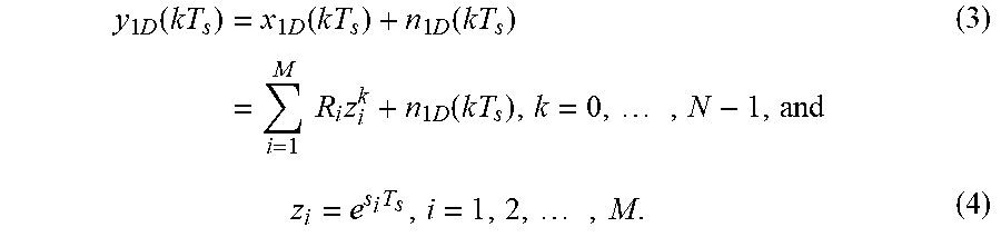
[0020] After scanning, the signals can be digitalized,
y 1 D ( k T s ) = x 1 D ( k T s ) + n 1 D ( k T s ) = i = 1 M R i z i k + n 1 D ( k T s ) , k = 0 , , N - 1 , and ( 3 ) z i = e s i T s , i = 1 , 2 , , M . ( 4 ) ##EQU00002##
[0021] It is also possible to model the useful signals directly with the 2D spectrum model. In digitalized form, the model is then, for example, like
y 2 D ( k 1 T s 1 , k 2 T s 2 ) = x 2 D ( k 1 T s 1 , k 2 T s 2 ) + n 2 D ( k 1 T s 1 , k 2 T s 2 ) = i = 1 M R i z 1 , i k 1 z 2 , i k 2 + n 2 D ( n T s 1 , l T s 2 ) , k 1 = 0 , , K 1 - 1 k 2 = 0 , , K 2 - 1 , ( 5 ) ##EQU00003##
where z.sub.1,i=e.sup.s.sup.1,i.sup.T.sup.s1, z.sub.2,i=e.sup.s.sup.2,i.sup.T.sup.s2, and s.sub.1,i=-.alpha..sub.1+j.omega..sub.1,i, s.sub.2,i=-.alpha..sub.2+j.omega..sub.2,i. s.sub.1,i or s.sub.2,i designate the complex frequencies in first or second dimension of 2D spectrum (two-dimensional spectrum of the radar sensor), and correspondingly T.sub.s1 and T.sub.s2 are the times in both dimensions. As the window function is normally known in an FFT (fast Fourier transform), the model of the spike of an individual point target is also known according to the Fourier transform. The unknowns in such models in particular only consist of the complex amplitudes and the frequency of the harmonic oscillation in the time range or the contribution, the phase and the position of the spike in the frequency range. Consequently, the problem can be solved either in the time range or the frequency range. If noise is present, the precision of the solution depends on the signal-noise ratio.
[0022] It is especially preferable for the problem to be solved in the time range without the influence of window functions, as the mathematical form of the window function is generally very complex. Furthermore, the 2D problem can be broken down into two one-dimensional problems. This means that the target separation can take place either in the first dimension or the second dimension, where modeling in Gl. 3 and Gl. 4 is preferentially used. Depending on the system setting, the separation abilities can be different in first and second dimensions. For example, in the 24 GHz system the bandwidth is frequently limited. For this reason, the resolution in the first dimension (distance) can be relatively more coarse in comparison to the resolution in the second dimension (speed). In this case, the separation can be performed in the second dimension, which constitutes an advantage. Furthermore, the separation in both dimension can, under certain circumstances, be comprehensively treated at the same time as modeling in Gl. 5.
[0023] It is possible that preprocessing, such as subsampling, will reduce the quantity of data before it is processed in the main processing step.
[0024] Preferably, target separation can be performed by the main processing step, which facilitates detection of the targets. Subject to certain assumptions, e.g. that there is a total of no more than.sup.M independent point targets in the overlap, the number of unknowns in the parameter estimation model are determined. If the number of (subsampled) values is the same or larger than the number of unknowns, this problem relating to parameter estimation is solvable. Known approaches include, for example, "matrix pencil methods" for solving mathematical problems of this kind. As examples, algorithms for using the matrix pencil method for solving the problem pursuant to the 1D model in Gl. 3 or the 2D model in Gl. 5 are disclosed in "Y. HUA, and T. K. SARKAR, Matrix Pencil Method for Estimating Parameters of Exponentially Damped/Undamped Sinusoids in Noise, IEEE Trans. on Acoustics, Speech, and Signal Processing, vol. 38, No. 5, pp. 814-824, May, 1990".
[0025] Furthermore, it is conceivable that the complex amplitudes R.sub.i and the frequencies .omega..sub.i (or .omega..sub.1,i and .omega..sub.2,i) are received as solutions. These frequencies that are contained here by means of parameter estimation are located in the baseband. In order to correctly obtain the distances and speeds (for target separation), frequency shifts .DELTA.f.sub.1 and .DELTA.f.sub.2 that may be performed in a preprocessing step must also be taken into account. The complex amplitudes contain the information on the performances and the phases of the targets, i.e. potentially of previously overlapping targets. Furthermore, differential phases between the (for example, three) receiving antennas can be used instead of the frequency tuple to determine the run time difference of the reflected signal and thus the azimuth angle. In other words, the targets can be separated and identified on the basis of the output of modeling in the main processing step.
[0026] According to a refinement of the invention, which constitutes an advantage, one option is for the following step to be performed prior to performance of the main processing step: [0027] Performance of a preprocessing step on the at least one provided spectrum, preferentially at a minimum for data compression, which determines a processing signal causing the modeling as part of the main processing step to be preprocessed performed on the basis of the processing signal.
[0028] In this context, data compression facilitates faster and more efficient processing of the spectrum in the subsequent main processing step. An advantage stems from treating the resulting output of the (entire) preprocessing step as the processing signal, where the preprocessing step can correspondingly feature several substeps. This facilitates comprehensive adaptation of the spectrum to determine the processing signal in order to be able to efficiently perform the main processing step.
[0029] Furthermore, one additional option is for the performance of the preprocessing step to further comprise the following (sub)step: [0030] Performance of separation between useful information and noise in the spectrum provided or partially preprocessed (by means of any preprocessing performed beforehand), preferentially by means of a threshold value method, preferably a CFAR threshold value method. This provides the advantage that noisy components of useful information can be separated by a simple method that can be executed quickly.
[0031] One possible option is for the input signal of the processing chain of the inventive method is a two-dimensional spectrum (2D spectrum), in which only a small part of the overall surface is filled with useful signals. The other surfaces then potentially only contain noise. A threshold method based on a CFAR (constant false alarm rate) can be used for this in order to distinguish the useful signal from the noise. The distribution density function of the noise can be estimated, for example, on the basis of the entire spectrum in one cycle or the scanning of the spectra over several cycles. Depending on the permissible error rate for the false alarm, the threshold for the useful signal is then determined by separating the inverse distribution function from the noise. In order to reduce the effort involved in signal processing, in certain cases only the local maximums or the spikes can be taken into consideration.
[0032] One additional option within the scope of the invention is for performance of the preprocessing step to further comprise the following (sub)step: [0033] Shift of at least one relevant frequency band in the provided or partially preprocessed spectrum into a lower frequency range, preferentially a baseband of the radar sensor, where the relevant frequency band comprises overlapping targets. This allows the processing speed to be significantly increased.
[0034] Furthermore, one option is for the performance of the preprocessing step to further comprise the following (sub)step: [0035] Transformation back of the provided or partially preprocessed spectrum into the time range in order to specify the processing signal as a time signal causing target separation to be performed on the basis of the modeling in the time range.
[0036] In this context, processing in the time range can be performed significantly more quickly than is possible in the alternative frequency range, which constitutes an advantage. According to Gl. 3 or Gl. 5, the overlapping of the point targets is modeled in the time range. 1D inverse finite Fourier transform (IFFT) or 2D IFFT allows the the provided or partially preprocessed spectrum to be transformed into the time range. The output in the time range can be formulated as presented in the following
{tilde over (x)}.sub.1D(kT.sub.s)=x.sub.1D(kT.sub.s).times.w.sub.1D(kT.sub.s), (6)
where w.sub.1D(kT.sub.s) is a 1D window function, or
{tilde over (x)}.sub.2D(k.sub.1T.sub.s.sub.1, k.sub.2T.sub.s.sub.2)=x.sub.2D(k.sub.1T.sub.s.sub.1, k.sub.2T.sub.s.sub.2).times.w.sub.2D(k.sub.1T.sub.s.sub.1, k.sub.2T.sub.s.sub.2), (7)
where w.sub.2D(kT.sub.s) is a 2D window function.
[0037] One additional advantage can be achieved within the scope of the invention if the preprocessing step further comprises the following (sub)step: [0038] performance of compensation of a window function relating to the provided or partially preprocessed spectrum.
[0039] In this way, target separation can be performed with improved accuracy by decoupling the window function from the signal {tilde over (x)}.sub.1D or {tilde over (x)}.sub.2D. This means that the processing time signals x.sub.1D or x.sub.2D can correspond to the model in Gl. 3 or Gl. 5. As the window function used (w.sub.1D or w.sub.2D) is usually known, the procedure for decoupling the window function can be preferably implemented by division. In particular, the output consists of estimates of the real time signals (x.sub.1D or x.sub.2D), and the estimates are designated as {tilde over (x)}.sub.1D or {tilde over (x)}.sub.2D.
[0040] In addition, it is conceivable within the scope of the invention is for performance of the preprocessing step to further comprise the following (sub)step: [0041] performance of subsampling for data compression relating to the provided or partially preprocessed spectrum.
[0042] The frequency bands relevant in the step consisting of the shift (of at least one relevant frequency band in accordance with the preprocessing step) can be narrow bands, and they can be moved into a lower frequency range by the preprocessing step. Consequently, a complete representation of the signals to be processed may not require the entire bandwidth of the original spectrum. For this reason, subsampling of the time signals {tilde over (x)}.sub.1D or {tilde over (x)}.sub.2D may be expedient. For example, the bandwidth amounts to 4 frequency bins in the spectrum. If the time signal is complex, only 4 frequency bins are theoretically required. This means that, in the example, the 64 scanning values can be reduced to 4 scanning values by means of subsampling. In order to be able to tolerate the noise in the modeling, 8 rather than 4 subsampling values are preferably taken in this case for practical reasons. As the boundary values in the window function are always very small, the values at the boundary of the estimates {tilde over (x)}.sub.1D or {tilde over (x)}.sub.2D are liable to being noisy. During the subsampling of {tilde over (x)}.sub.1D or {tilde over (x)}.sub.2D, it is consequently especially preferable not to record the boundary values. The subsampled values from {tilde over (x)}.sub.1D or {tilde over (x)}.sub.2D can be understood to be the measurement in the model pursuant to Gl. 3 or Gl. 5.
[0043] According to a further advantage, one option is for the following step to be performed subsequent to performance of the main processing step: [0044] Performance of a postprocessing step during which a plausibility check of modeling output of the parameter estimation is carried out in order to perform target separation depending on the plausibility check. This makes it possible to ensure the correctness of the output of the main processing step.
[0045] In a further option, it is possible for the modeling to be effected in accordance with the main processing step in two dimensions or alternatively only in one dimension. The use of two dimensions can potentially lead to improved modeling output, whereas modeling in only one dimension increases the speed.
[0046] Another object of the invention is a radar system for a vehicle that is operated in accordance with an advantage of the system at 24 GHz and/or 77 GHz, featuring: [0047] a radar sensor for detecting a detection signal (such as the emission of at least one signal and/or the reception of reflected signals, preferentially with a frequency in the range around 24 GHz and/or 77 GHz for the purpose of detecting targets in the surroundings of the vehicle, [0048] a processing device for processing the detection signal by means of an inventive method.
[0049] As a result, the inventive radar system brings about the same advantages as were described in detail in relation to an inventive method.
[0050] A further advantage may arise from the invention if the vehicle takes the form of a motor vehicle, specifically a passenger or goods vehicle and/or an electric vehicle or hybrid vehicle.
[0051] The processing device takes the form, for example, of a signal processor, where a two-dimensional spectrum of the radar sensor preferentially forms the input signal for the processing device for performing an inventive method. In particular, the use in this context of the inventive method during operation of the processing device offers significant speed and performance advantages, even if simple (embedded) hardware is used.
[0052] Another object of the invention is a computer program product that can be executed by a processing device such as a processor or microcontroller or the like, where execution of the inventive computer program product brings about performance of the following steps by the processing device: [0053] Provision of at least one two-dimensional spectrum, which is specific for detection of targets of at least one radar sensor, [0054] Performance of a main processing step for target separation, in which modeling on the basis of the at least one provided two-dimensional spectrum is performed by means of parameter estimation in order to preferentially perform detection of the targets.
[0055] As a result, the inventive computer program product brings about the same advantages as were described in detail in relation to an inventive method and/or radar system. It is additionally advantageous if the computer program product is designed in such a way as to perform an inventive method and/or operate an inventive radar system.
BRIEF DESCRIPTION OF THE DRAWINGS
[0056] Reference is now made more particularly to the drawings, which illustrate the best presently known mode of carrying out the invention and wherein similar reference characters indicate the same parts throughout the views.
[0057] FIG. 1 is a block circuit diagram of a radar sensor of an inventive radar system.
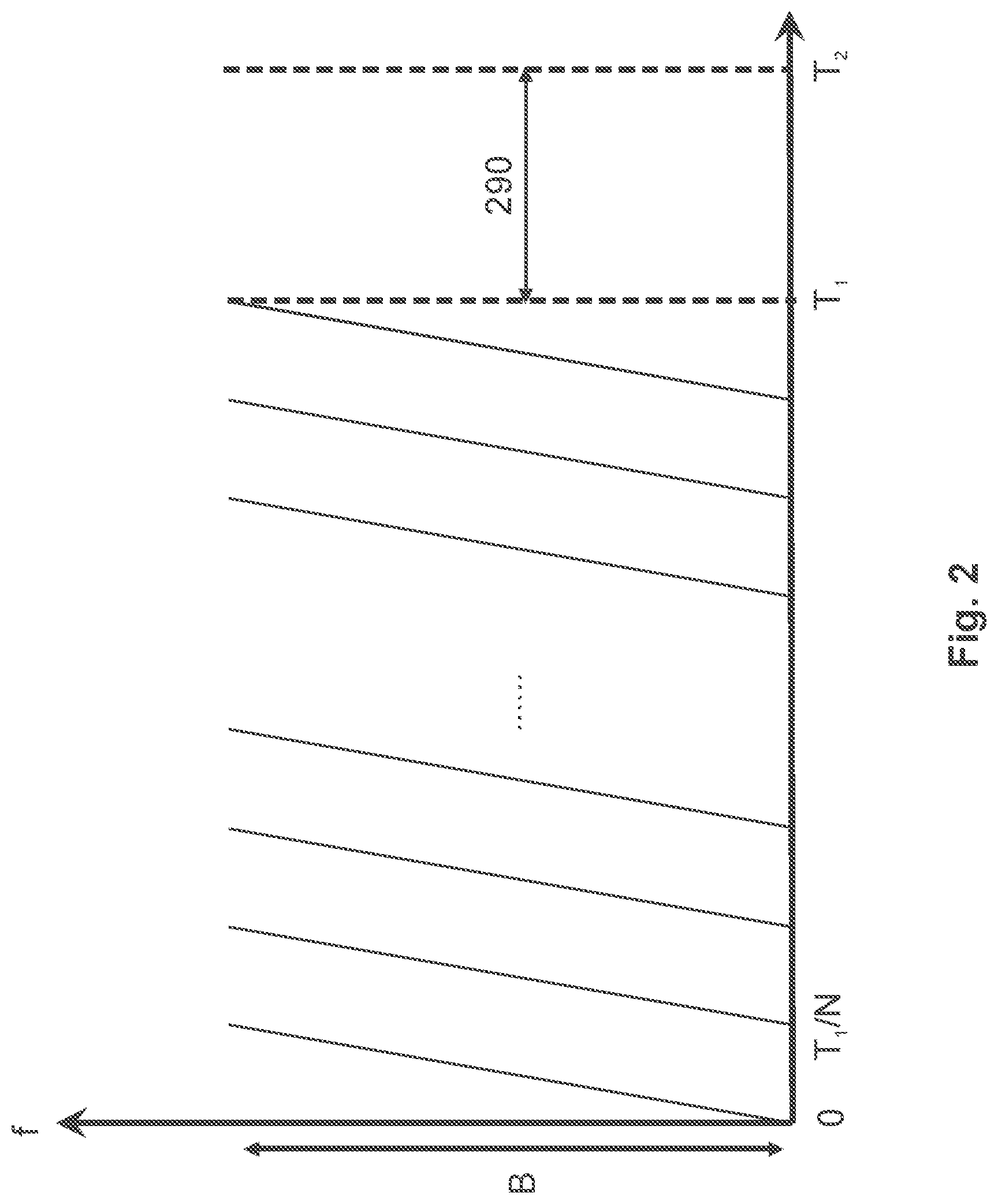
[0058] FIG. 2 is a transmission scheme with an inventive radar system.
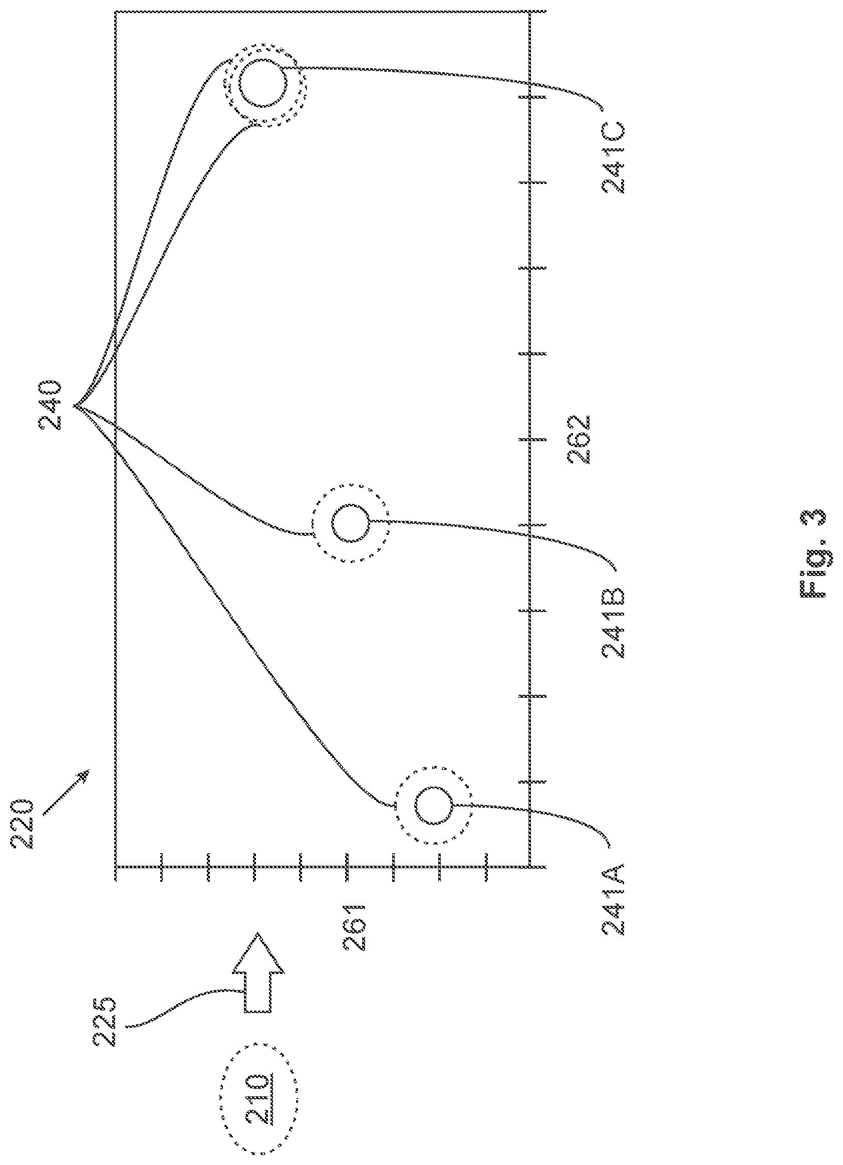
[0059] FIG. 3 is an example of a two-dimensional spectrum (2D distance-Doppler spectrum).
[0060] FIG. 4 is an exemplary sequence of an inventive method.
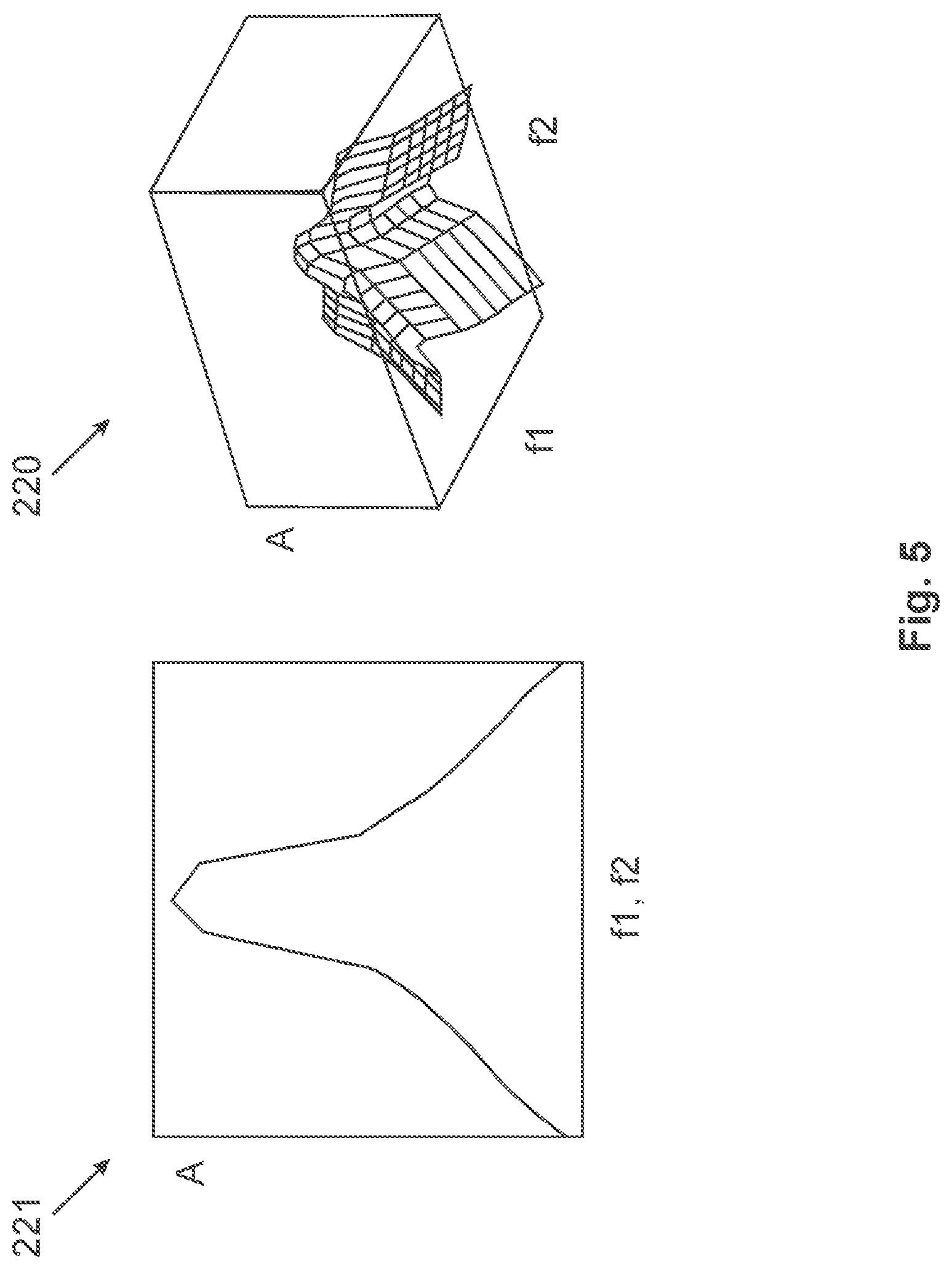
[0061] FIG. 5 is a visualization of a spike pattern spectrum.
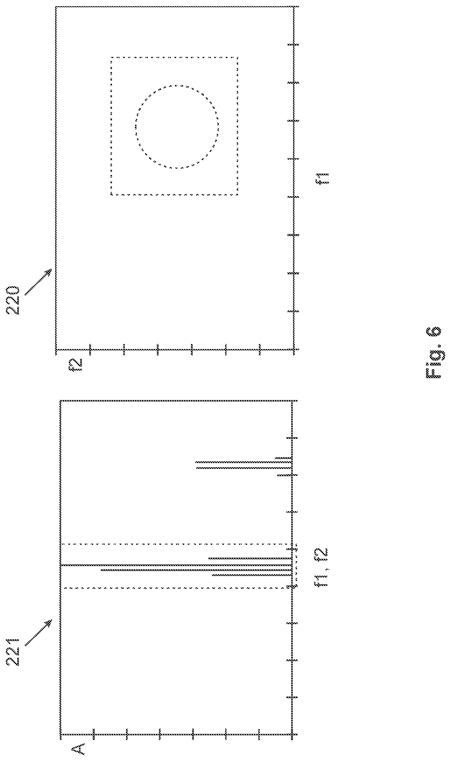
[0062] FIG. 6 is a visualization of a relevant frequency band.
[0063] FIG. 7 is a visualization of a shift in the frequency band.
[0064] FIG. 8 is a visualization of a window function compensation.
DETAILED DESCRIPTION OF THE DRAWINGS
[0065] An inventive radar system 1, as schematically depicted in FIG. 1, can comprise at least one radar sensor 10. In this context, the radar sensor 10 can be fastened to a vehicle 2, for example in the area of the radiator grill and/or in the side area in order to detect targets 240 in the surroundings of the vehicle 2, for example in the direction of travel and/or in a side area of the vehicle 2. The radar sensor 10 preferably comprises a transmission antenna 20 and at least three receiving antennas 30. In this context, the receiving antennas 30 may be arranged equidistantly in x orientation. Furthermore, the transmission antennas 20 can feature both a certain distance in the x orientation and a certain distance in the y orientation to each other and operate in time multiplex (alternating, time-delayed transmission of the same signal). The x and y orientations are each visualized schematically by arrows. Furthermore, a processing device 300 of the radar sensor 10, such as a processor or the like, is shown that can feature an analog to digital converter 310 and/or a computer program product 400. A further option for operation of the radar sensor 10, for example, the transmission antenna 20 is a digital-to-analog converter 40.
[0066] One option is for the radar sensor 10 to use a rapid succession of ramps as transmission scheme for determining target parameters with regard to the targets 240. In doing so, within one cycle of duration T.sub.1 N frequency ramps of duration T.sub.1/N can be transmitted consecutively (see FIG. 2). The current transmission frequency f of the frequency ramps may in this context be altered linearly within the transmission bandwidth B (linear frequency modulation). The processing 290 of the data received within time T.sub.1 can be subsequently carried out in time period T.sub.2-T.sub.1 so that the entire measuring cycle corresponds to a duration of T.sub.2. As an example, the processing 290 in this context comprises at least the steps of an inventive method 100, so that a processing device 300 is being operated for processing 290 at least in this time period T.sub.2-T.sub.1.
[0067] The reflected signal in the receivers is initially mixed with the transmission signal down the base band and scanned and is at time point T.sub.1 stored in a M.times.N matrix (M scan values per ramp, N ramps). This means that the data of this matrix can be regarded as detection signal 210 of the radar sensor 10. Subsequently, transformation 225 of the 2D base band signal (detection signal 210) stored in such a way can be performed in the 2D frequency range in order to make the two-dimensional spectrum 220 available. The relevant point targets (detected targets 240 in the surroundings) are displayed in the 2D spectrum 220 as spikes 241A, 241B, 241C (see FIG. 3). In this context, the spikes in the digram of the two-dimensional spectrum 220 are shown with a vertical orientation 261 of the spectrum 220 in accordance with a first dimension and with a horizontal orientation 262 of the spectrum 220 in accordance with a second dimension. It is an advantage for the spectrum 220 to be designed as a 2D distance-Doppler spectrum, so that the vertical orientation 261 (f1) is dependent on the distance to a target 240 and the horizontal orientation 262 (f2) is dependent on a relative speed to the target 240.
[0068] It is possible for the spectrum 220 to feature fewer spikes 241A, 241B, 241C than there are actual targets 240 (point targets). This makes it possible for only 3 spikes in the spectrum to be visible, for example the spikes 241A, 241B and 241C, despite the existence, for example, of 4 point targets 240. The spike 241C expands further than the two other peaks 241A, 241B, and two point targets 240 overlap each other at this position. In accordance with conventional detection methods (for example, a local maximum principle), this therefore results in a signal consisting of 2 base frequencies f.sub.1 (first dimension) and f.sub.2 (second dimension) for one spike. The frequency f.sub.1 may under certain circumstances be exclusively dependent on the distance R of the target and the frequency f.sub.2 in particular exclusively dependent on the relative speed v. The accuracy of the frequencies f.sub.1 and f.sub.2 can also be improved, for example, by interpolation with adjacent points. Furthermore, differential phases between the 3 receiving antennas 30 can be used instead of the frequency tuple to determine the run time difference of the reflected signal and thus the azimuth angle. The raw target parameters determined in this way form (potentially together with additional information such as the signal level and reliability of the values generated) what is referred to as a raw target from which objects can potentially be formed in a further processing step using tracking algorithms. The frequencies f.sub.1 and f.sub.2 resulting from spike 241C are, however, falsified on account of the overlapping of two point targets 240.
[0069] FIG. 4 schematically visualizes an inventive method 100. It shows that the method can be broken down into a preprocessing step 110, a main processing step 120 and a postprocessing step 130. In accordance with the preprocessing step 110, it is possible for a first step 111 to be performed, specifically the search for local maximums or spikes (e.g. by means for a threshold value method for separating useful information and noise. Furthermore, according to a second step 112, selection of potential overlaps can be performed. In a third step 113, it is possible to perform a shift of a relevant frequency band and/or an inverse (fast) Fourier transform in order to transfer the spectrum 220 into the time range. In a fourth step 114, it is subsequently possible to compensate a window function and in a fifth step 115 to perform downsampling in order to maintain the processing signal 230. In this context, it is possible to select a different sequence of steps or to dispense with individual steps or potentially introduce further steps. As part of the main processing step 120, the parameter estimation is performed on the basis of the processing signal 230 and, optionally the plausibility check as part of the postprocessing step 130.
[0070] It is possible for only the local maximums or spikes to be taken into account in the spectrum 220 according to the second step 112 in order to reduce the effort needed for signal processing. This is depicted in more detail below on the basis of FIG. 5. In this respect, a one-dimensional spike pattern spectrum 221 and a two-dimensional spike pattern spectrum 220 are schematically depicted (with amplitude A and frequencies f1 and f2; as an alternative, the one-dimensional spectrum 221 may optionally be frequency f1 or f2). It is possible for most of the spikes identified in the spectra to be treated as point targets. Selection of the potential overlaps in the 2D spectra can, for example, be implemented by means of a cross correlation. If the separation task is handled in 1D, the 1D spike in the spectrum to be examined can be folded with a 1D spike pattern (or alternatively the 1D FFT output of the window function) either in the first or the second dimension. Such folding is, for example, normed on the spike to be examined. It is subsequently possible to perform a comparison to a predefined threshold value. If the cross correlation is smaller than the threshold value, it is very likely that the spike examined constitutes an overlap of several point targets. If the problem is to be treated in accordance with with model in Gl. 5, the cross correlation should be folded here with a 2D spike pattern (or the 2D FFT output of the window function.
[0071] FIG. 6 contains a representation of a relevant frequency band in the 1D spectrum 221 and in the 2D spectrum 220 (with the amplitude A and the frequencies f1 and f2, or in the 1D range either f1 or f2). In order to reduce the computing power requirements in the time range, the relevant frequency band according to FIG. 7 and according to a third step 113 can be shifted into the base band. These frequency shifts are identified with df1 and df2 in the first or second dimension. The signal can subsequently be transformed into the time range (e.g by means of inverse Fourier transform).
[0072] In a fourth step 114, decoupling of the window function (compensation) can be carried out. FIG. 8 shows an example of how the window function 280 influences the time signal (see window function 280 with the broken line, and time signal with window function 281). This influence can be reversed by the compensation, e.g. by means of division of the known window function thus giving rise to the compensated time signal 282. Furthermore, the time signal can correspond to the processing signal 230.
[0073] According to a further advantage with the inventive method 100, the plausibility can be verified of the frequencies in the solutions in accordance with the postprocessing step 130 (as a consequence of the unavoidable noise in the system). One potential criteria is that the frequencies may not exceed the upper and lower limits of the selected frequency bands in FIG. 7.
[0074] The previous explanation of the designs only describes this invention using examples. Of course, individual features of these designs can be combined with one another in any way without going beyond the scope of this invention, provided that these features are technologically useful.
LIST OF REFERENCE NUMBERS
[0075] 1 Radar system [0076] 2 Vehicle [0077] 10 Radar sensor [0078] 20 Transmission antenna [0079] 30 Receive antennas [0080] 40 Digital-to-analog converter [0081] 100 Method [0082] 110 Preprocessing step [0083] 111 First step [0084] 112 Second step [0085] 113 Third step [0086] 114 Fourth step [0087] 115 Fifth step [0088] 120 Main processing step [0089] 130 Postprocessing step [0090] 210 Detection signal [0091] 220 Spectrum, 2D spectrum [0092] 221 1D spectrum [0093] 225 Transformation [0094] 230 Processing signal, time signal [0095] 240 Target [0096] 241A First spike [0097] 241B Second spike [0098] 241C Third spike [0099] 261 Vertical orientation, first dimension (f1) [0100] 262 Horizontal orientation, second dimension (f2) [0101] 280 Window function [0102] 281 Time signal with window function [0103] 282 Compensated time signal [0104] 290 Processing of receive signal [0105] 300 Processing device [0106] 310 Analog-digital converter [0107] 400 Computer program product [0108] f Frequency [0109] df1 First frequency shift [0110] df2 Second frequency shift [0111] A Amplitude [0112] B Transmission bandwidth
* * * * *
D00000
D00001
D00002
D00003
D00004
D00005
D00006
D00007
D00008
XML
uspto.report is an independent third-party trademark research tool that is not affiliated, endorsed, or sponsored by the United States Patent and Trademark Office (USPTO) or any other governmental organization. The information provided by uspto.report is based on publicly available data at the time of writing and is intended for informational purposes only.
While we strive to provide accurate and up-to-date information, we do not guarantee the accuracy, completeness, reliability, or suitability of the information displayed on this site. The use of this site is at your own risk. Any reliance you place on such information is therefore strictly at your own risk.
All official trademark data, including owner information, should be verified by visiting the official USPTO website at www.uspto.gov. This site is not intended to replace professional legal advice and should not be used as a substitute for consulting with a legal professional who is knowledgeable about trademark law.