Decking Support System
Bowie; Stuart
U.S. patent application number 16/960250 was filed with the patent office on 2021-03-11 for decking support system. The applicant listed for this patent is Kinley Systems Limited. Invention is credited to Stuart Bowie.
| Application Number | 20210071430 16/960250 |
| Document ID | / |
| Family ID | 1000005235949 |
| Filed Date | 2021-03-11 |
| United States Patent Application | 20210071430 |
| Kind Code | A1 |
| Bowie; Stuart | March 11, 2021 |
DECKING SUPPORT SYSTEM
Abstract
A decking support system including a plurality of decking support elements (30), engageable together to form a planar decking support surface suitable to receive decking, each decking support element (30) including sidewalls (50) extending in a longitudinal direction, a base, and an upper surface (90), the upper surface including a first surface for supporting decking and a second surface below the first surface including at least one fin (150) extending towards the first surface.
| Inventors: | Bowie; Stuart; (Sussex, GB) | ||||||||||
| Applicant: |
|
||||||||||
|---|---|---|---|---|---|---|---|---|---|---|---|
| Family ID: | 1000005235949 | ||||||||||
| Appl. No.: | 16/960250 | ||||||||||
| Filed: | November 5, 2018 | ||||||||||
| PCT Filed: | November 5, 2018 | ||||||||||
| PCT NO: | PCT/GB2018/053208 | ||||||||||
| 371 Date: | July 6, 2020 |
| Current U.S. Class: | 1/1 |
| Current CPC Class: | E04F 15/02183 20130101; E04F 2015/02066 20130101; E04F 15/02044 20130101; E04B 5/10 20130101 |
| International Class: | E04F 15/02 20060101 E04F015/02; E04B 5/10 20060101 E04B005/10 |
Foreign Application Data
| Date | Code | Application Number |
|---|---|---|
| Nov 6, 2017 | GB | 1718345.0 |
Claims
1. A decking support system including: a plurality of decking support elements, engageable together to form a planar decking support surface suitable to receive decking; each decking support element including: sidewalls extending in a longitudinal direction, a base, and an upper surface, the upper surface including a first surface for supporting decking and a second surface below the first surface including at least one fin extending towards the first surface.
2. The decking support system of claim 1, wherein said at least one fin is a plurality of fins.
3. The decking support system of claim 1, wherein said at least one fin includes a first end attached to said second surface, and a second end which extends towards but does not reach said first surface.
4. The decking support system of claim 3, wherein said second end includes sloped surfaces.
5. The decking support system of claim 3, wherein said second end is arrow-shaped.
6. The decking support system of claim 1, wherein each said at least one fin is separated from at least one neighboring fin by a gap.
7. The decking support system of claim 1, wherein said at least one fin extends in the direction of, and along the length of, said sidewalls.
8. The decking support system of claim 1, wherein said decking support elements are made from aluminum.
9. The decking support system of claim 6, wherein said adapted to receive a screw spike in said gap.
10. A decking support element for a decking support system of claim 1.
Description
[0001] The present invention is directed to a support structure for, for example, decking, or other surfaces.
[0002] Creating a surface around houses, office blocks or other structures which may be utilised to the benefit of the occupiers is well known, and requires the surface to be level for example to provide support, and to be aesthetically pleasing. Such surfaces include walkways, pathways, gardens, patios and other surfaces and can also include terraces and balconies.
[0003] One way to provide such surfaces is to install decking, generally made of elements such as planks of wood, a wood composite, rubber, plastics, plastics composite or other suitable material and laid side by side over the natural surface. Often the natural surface is not flat, and can be of poor quality in which case a decking surface may be laid in an elevated orientation over the natural surface, and this is accomplished by placing pedestals on the natural surface, the height of the pedestals variable such that decking support elements placed on the pedestals provide a planar surface upon which the decking elements may be laid. Such decking support elements are conventionally made from wood, wood composite, recycled plastics or other material. An example of such an arrangement may be seen in GB160866.1.
[0004] The decking elements may be laid onto the decking support and secured thereto either by invasive or non-invasive means. Invasive means include screws, nails or other means which may provide points of entry to water which, for decking support elements made from wood, wood composite or some other materials, may eventually result in a degraded product, and non-invasive means which may require cooperative rebating of the decking elements to provide for them to link together, which has the disadvantage that for decking elements which are moulded rather than extruded any significant costs are incurred. In addition, relying on non-invasive means to engage decking elements together to provide a decking surface which then rests on the decking support elements, rather than engaging the decking elements to the decking support structures directly, means that the decking elements do not engage with the decking support elements, and this may be considered insufficiently secure.
[0005] Latterly, the technology relating to decking planks has improved enormously such that decking board surface quality and longevity outstrips that of decking support structures to a significant degree, the technology relating to decking support structures lagging, and making such support structures increasingly the weakest link in relation to robust decking systems.
[0006] Where decking support elements are made from aluminium to avoid the disadvantages of other materials in terms of water and other time-dependent damage, it is not straightforward to provide a means for such aluminium elements to receive screws or to engage with other fixing means. While it is possible to drill into aluminium to provide for screw attachments, screws suitable for this purpose are likely to damage the decking board surface.
[0007] The present invention is directed to overcoming at least some of these disadvantages.
[0008] The present invention provides, according to a first aspect, a decking support system including a plurality of decking support elements, engageable together to form a planar decking support surface suitable to receive decking, each decking support element including sidewalls extending in a longitudinal direction, a base, and an upper surface, the upper surface including a first surface for supporting decking and a second surface below the first surface including at least one fin extending towards the first surface.
[0009] Preferably the at least one fin is a plurality of fins.
[0010] Preferably the fins include a first end attached to the second surface, and a second end which extends towards but does not reach the first surface.
[0011] Preferably the second end includes sloped surfaces.
[0012] Preferably the second end is arrow-shaped.
[0013] Preferably each fin is separated from at least one neighbouring fin by a gap.
[0014] Preferably the fins extend in the direction of, and along the length of, the sidewalls.
[0015] Preferably the decking support elements are made from aluminium.
[0016] Preferably the fins are adapted to receive a screw spike in the gap.
[0017] The present invention also provides a decking support element for the described decking support system.
[0018] Preferred embodiments of the present invention will now be described by way of example only and with reference to the accompanying drawings in which:
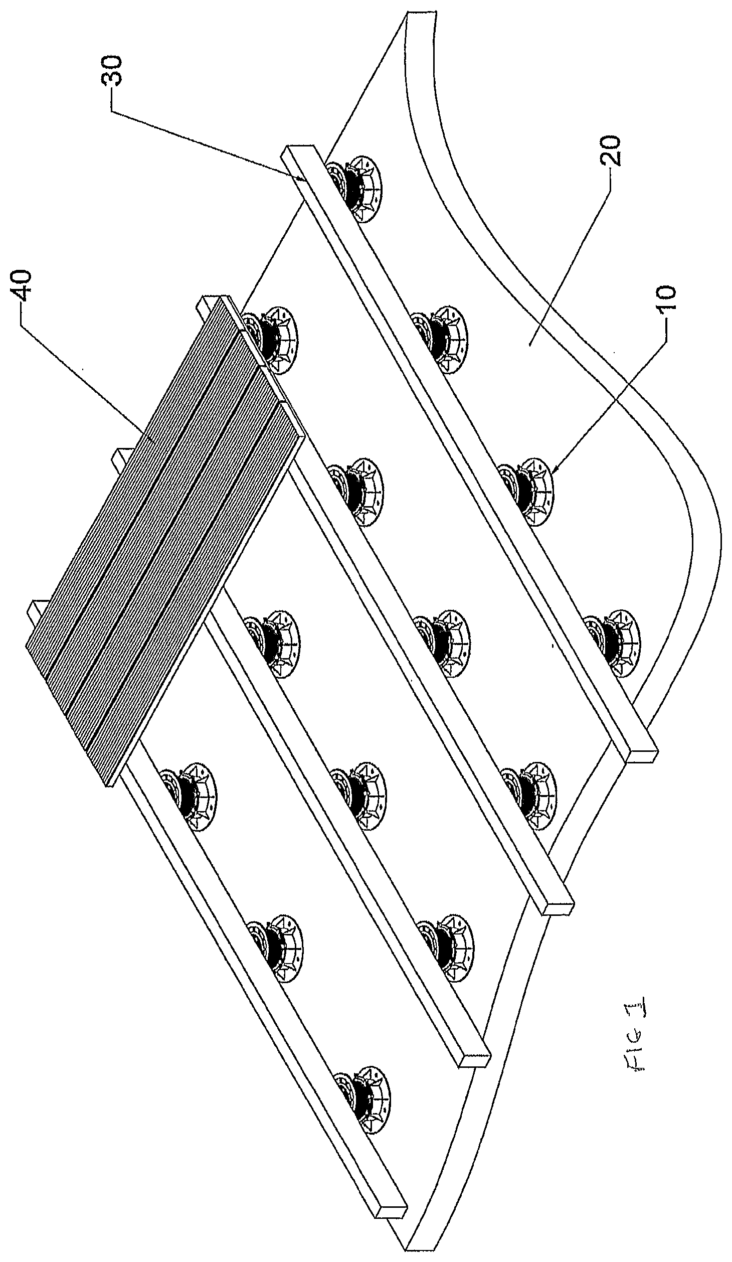
[0019] FIG. 1 shows a conventional decking support system partially constructed, including pedestals with decking support elements resting thereon, and with decking planking partially overlaying the decking support elements,
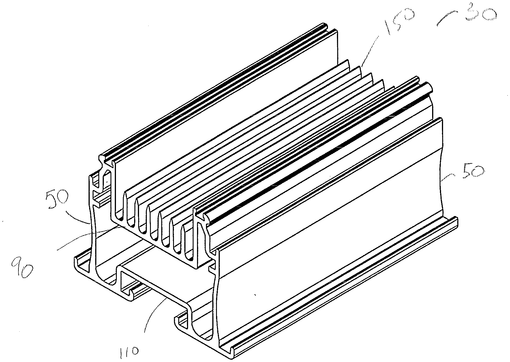
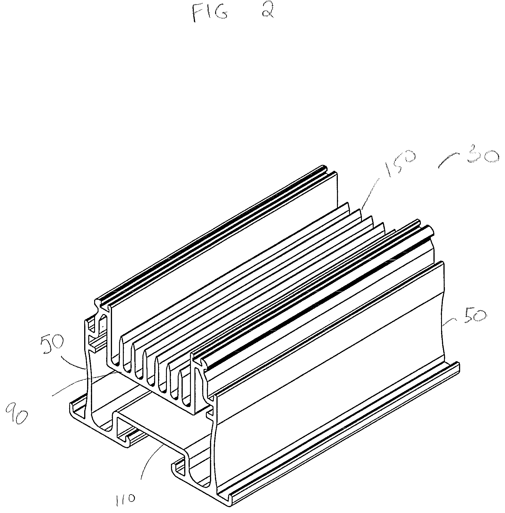
[0020] FIG. 2 shows a perspective view of a decking support element in accordance with the present invention,
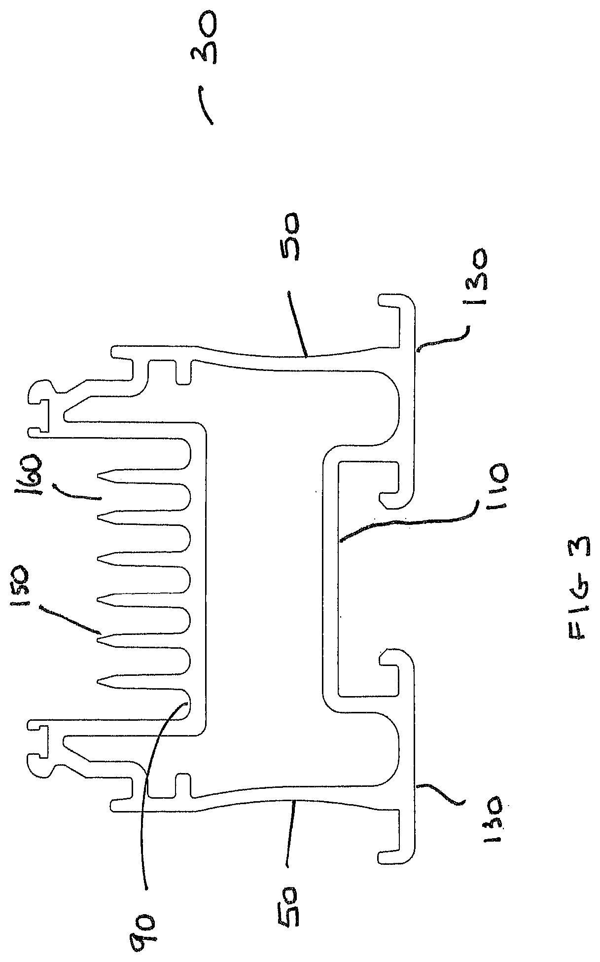
[0021] FIG. 3 shows a cross sectional view of the decking support element of FIG. 2, and
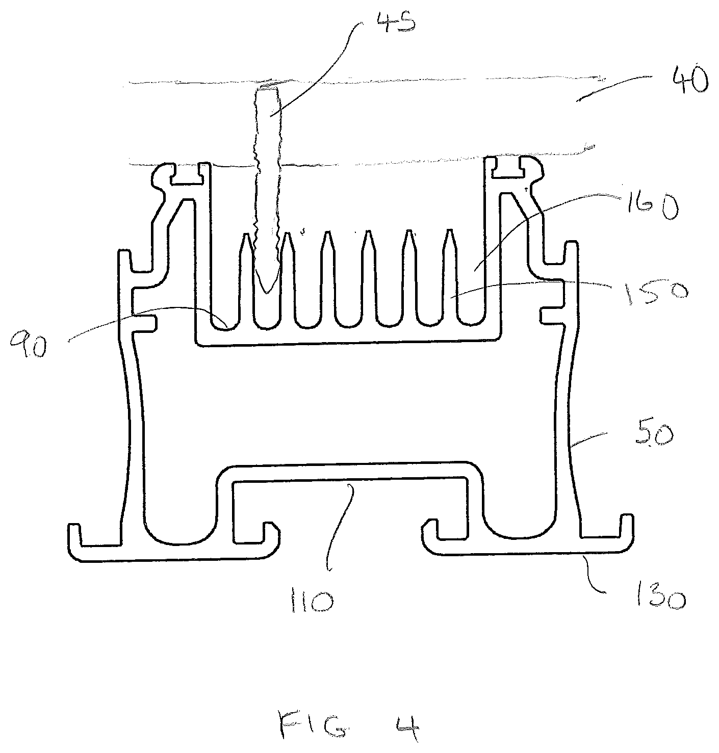
[0022] FIG. 4 shows a cross sectional view of the decking support element of FIG. 2 with a decking plank secured thereon via a screw engaged with fins.
[0023] FIG. 1 shows a conventional arrangement for supporting decking in which pedestals 10 are positioned on an original surface 20, and decking support elements 30 are provided to rest on the pedestals and provide a support structure for a decking surface. FIG. 1 shows decking planks 40 partially laid onto the support structure to provide a decking surface above the original surface 20. Each pedestal 10 may be adapted to be of a height which, when arranged with other pedestals on a surface, ensures that the decking is flat over the entire surface, and, where the original surface is uneven, this can be achieved by for example individual pedestals being `jacked` to different heights. FIG. 2 shows a perspective view of a decking support element 30 each end of which, as shown in FIG. 3, has a generally square cross section, the decking support element suitable for use as part of a support structure for decking in accordance with the present invention. A plurality of such decking support elements may be laid on a plurality of pedestals 10 in the manner shown in FIG. 1. Conventionally such support structure components are provided in fixed lengths which are placed end to end or cut to size to suit. The same is contemplated in the present invention.
[0024] FIG. 3 shows a cross sectional view of the decking support element 30 of FIG. 2.
[0025] As can be seen in FIGS. 2 and 3, the decking support element includes side walls 50 extending substantially parallel to each other in a longitudinal direction, with upper surface 90 and lower wall 110 also extending substantially parallel to each other in a longitudinal direction, the longitudinal length of respective walls 50, 90, 110 defining the length of the element 30. Feet 130 are positioned at the end of each side wall 50 at the base of the element, extending substantially parallel to the upper surface 90 and lower wall 110, and orthogonally to side walls 50.
[0026] Upper surface 90, while generally planar, includes fins 150 extending upwardly and away from surface 90, in a direction substantially parallel to sidewalls 50. The fins provide anchorage for screws, nails or other fixing means which may be utilised to secure respective decking planks or suchlike to the decking support elements when constructing a surface, for example as shown in FIG. 1.
[0027] FIG. 4 shows a decking plank 40 positioned on a decking support element 30 and secured thereto by a screw 45 which extends through the decking plank 40, and into gap 160 between fins 150.
[0028] As can be seen in FIGS. 2-4, fins 150 are positioned on upper surface 90 of the decking support elements in an arrangement such that screws and other fixing elements may be received in gaps 160 between fins, the fins being sufficiently numerous on the upper surface 90 to provide flexibility in positioning screws on the decking surface, and thereby assisting with fixing decking planks to the decking support elements.
[0029] It is contemplated that the fins do not have a flat top, but rather that the top surface of each fin is arrow shaped, with sloping sides towards the end of the fin remote the upper surface 90. Fins extend in a direction away from surface 90 sufficiently far that the gaps between fins are suitable to receive the screw spike in the gaps between the fins, and provide sufficient engagement between the screw spike and the fin walls for secure engagement thereof. The height of the fins is also influenced by the difficulties in manufacturing the device.
[0030] The fins are also sufficiently strong to provide for a secure fixing, but sufficiently flexible to accommodate a variety of orientations of screws which are utilised to secure decking on the decking support elements. In particular, with an `arrow-head` shape at the top of each fin a screw urged into a decking portion, to secure the decking portion onto the decking support, will approach the fins either straight-on or at an angle to the fin walls, aiming for the screw spike to enter the gap between fins so that the screw can engage with the fin walls and screw securely in place.
[0031] Generally, as the screw spike approaches the fins, an end remote the screw head will engage the top or a sloping side of a fin and will deflect slightly (and in addition the fin may deflect slightly) to enter into the gap between the fin wall and the wall of an adjacent fin. As the screw turns it engages strongly with both fin walls to secure the screw in place.
[0032] The number of fins is not generally fixed, the more fins provided the smaller the gap between fins and the smaller the screws that can be accommodated. It is contemplated that there will be between 1 and 10 fins, although 3, 4, 5 or 6 fins are more likely to be appropriate in most cases.
[0033] The arrangement is such that each decking support element 30 may be placed on a, or on a series of, pedestals 10, arranged on a surface for example the surface 20 of FIG. 1, to be covered with planks of decking 40, or other suitable surface. With the planks of decking 40 placed on the decking support structures, screws or other means may be inserted or otherwise engaged with the decking planks and screwed into the gaps 160 between the fins 150 of the decking support structures.
[0034] Decking planks may include openings for such screws, or they may be free of such openings so that the planks may be secured to the decking support structures at will. If the decking planks do not include openings, a screw may be urged through the decking plank into the area including fins 150. It is contemplated that the screws are of a type, and the decking planks are of type, that the opening created by the screw closes over the screw head so that it is not evident that a screw has been placed therein. This reduces the likelihood of water entering into the opening provided by the screw. In addition, the material from which many decking planks is made is a composite that is impervious to water, so that any water that does enter into such an opening does not degrade the decking plank.
[0035] As stated, the plurality of fins ensures that the screws or other engaging means will enter into an opening 160 so that the walls of adjacent fins secure the screw therein, or will enter sufficiently close to an opening 160 that the sloping upper walls of the closest fin may urge the screw spike to one side so that the screw can be secured between adjacent fins. This means that provided a screw engages with the decking plank in a predetermined general area, it will engage with a suitable gap and secure the decking plank in place, providing flexibility in positioning the screws and ensuring that the planks will securely engage with the decking support structure.
[0036] In use, where it is desired to provide decking on a surface area, for example around a building or on a balcony or other surface, a series of pedestals 10 may conventionally be provided to generate a broadly planar upper surface on which the decking may ultimately be placed. A series of first generally elongate decking support elements 30 in accordance with the present invention may then be placed on the pillars in a uniform, and generally conventional, manner.
[0037] The decking support elements may be placed on the pedestals, or other support, via feet 130. In accordance with the present invention a next step provides for the first decking support elements 30 to be linked with further decking support elements 30 to provide a secure and stable arrangement upon which decking may be placed. An example of such a process is disclosed in GB1608661.3.
[0038] Once the decking support elements are securely in position, planks of for example wood, wood composite, rubber, plastics, plastics composite or other suitable material may be positioned thereon and secured thereto by screws which extend through the decking planks and into gaps 160 between fins 150 of the decking support elements, thereby securing the planks to the decking support elements. Screws may be inserted into the decking elements in approximate positions and will still engage with openings 160 between fins 150 to secure the decking elements thereto. Alternative linking means may be relied upon to engage with fins 150, and gaps 160 to secure the planks to the decking support elements.
[0039] Decking in accordance with the present invention provides for a planar surface in which decking and decking support elements may rely on screws or other potentially invasive linking means to secure decking to decking supports on pedestals, without the disadvantages which generally accompany invasive linking means, including providing entry points for water leading to deterioration of the decking support elements. In addition, the present invention has the advantage that screws or other linking means may be inserted where convenient, rather than being constrained by receiving features at predetermined positions on the decking support element.
[0040] It is contemplated that the decking support structures will be formed from Aluminium or other suitable substance. Fins may be painted black or another suitable colour to ensure they are not unnecessarily visible.
[0041] The invention is not restricted to the details of the foregoing embodiments. For example, the present invention is contemplated to cover any suitable number fins 150 on upper surface 90, for example there may be one fin, or more than one fin. The present disclosure shows six fins, but three, four, five or any other suitable number of fins is contemplated. In addition, the fins 150 may include a variety of orientations and spacings and are not contemplated to be restricted to a direction parallel to sidewalls 50 of the decking support elements; for example, there may be a plurality of fins positioned in an orthogonal orientation to, and along, sidewalls 50. While the decking support element is contemplated to be placed on pillars it is contemplated that the arrangement of the present invention is adaptable to be used on different surfaces, for example a conventional surface or on alternative means to provide a planar surface.
* * * * *
D00000
D00001
D00002
D00003
D00004
XML
uspto.report is an independent third-party trademark research tool that is not affiliated, endorsed, or sponsored by the United States Patent and Trademark Office (USPTO) or any other governmental organization. The information provided by uspto.report is based on publicly available data at the time of writing and is intended for informational purposes only.
While we strive to provide accurate and up-to-date information, we do not guarantee the accuracy, completeness, reliability, or suitability of the information displayed on this site. The use of this site is at your own risk. Any reliance you place on such information is therefore strictly at your own risk.
All official trademark data, including owner information, should be verified by visiting the official USPTO website at www.uspto.gov. This site is not intended to replace professional legal advice and should not be used as a substitute for consulting with a legal professional who is knowledgeable about trademark law.