Lawn Refuse Bag
Chen; Shifeng ; et al.
U.S. patent application number 16/703272 was filed with the patent office on 2021-03-11 for lawn refuse bag. The applicant listed for this patent is Pratt Corrugated Holdings, Inc.. Invention is credited to Shifeng Chen, Greg Sollie, Jamie Waltermire.
| Application Number | 20210070541 16/703272 |
| Document ID | / |
| Family ID | 1000004526325 |
| Filed Date | 2021-03-11 |


| United States Patent Application | 20210070541 |
| Kind Code | A1 |
| Chen; Shifeng ; et al. | March 11, 2021 |
LAWN REFUSE BAG
Abstract
Example aspects of a lawn refuse bag and method for using a lawn refuse bag are disclosed. The lawn refuse bag can comprise a bag body defining a top end and an interior cavity configured to receive lawn refuse, the top end defining a top opening, the top end configurable in an open orientation and a closed orientation; a first handle assembly coupled to the bag body at the top end; and a second handle assembly coupled to the bag body at the top end, wherein, in the closed orientation, the first handle assembly is configured to engage the second handle assembly, and in the open orientation, the first handle assembly is configured to disengage the second handle assembly.
| Inventors: | Chen; Shifeng; (Newport News, VA) ; Sollie; Greg; (Sharpsburg, GA) ; Waltermire; Jamie; (Peachtree City, GA) | ||||||||||
| Applicant: |
|
||||||||||
|---|---|---|---|---|---|---|---|---|---|---|---|
| Family ID: | 1000004526325 | ||||||||||
| Appl. No.: | 16/703272 | ||||||||||
| Filed: | December 4, 2019 |
Related U.S. Patent Documents
| Application Number | Filing Date | Patent Number | ||
|---|---|---|---|---|
| 62896935 | Sep 6, 2019 | |||
| Current U.S. Class: | 1/1 |
| Current CPC Class: | B65F 2001/1653 20130101; B65F 2240/138 20130101; B65F 2220/1063 20130101; B65F 1/14 20130101 |
| International Class: | B65F 1/14 20060101 B65F001/14 |
Claims
1. A lawn refuse bag comprising: a bag body defining a top end and an interior cavity configured to receive lawn refuse, the top end defining a top opening, the top end configurable in an open orientation and a closed orientation; a first handle assembly coupled to the bag body at the top end; and a second handle assembly coupled to the bag body at the top end, wherein, in the closed orientation, the first handle assembly is configured to engage the second handle assembly, and in the open orientation, the first handle assembly is configured to disengage the second handle assembly.
2. The lawn refuse bag of claim 1, wherein the bag body comprises a first end panel, a second end panel, a first sidewall panel, a second sidewall panel, and a base panel.
3. The lawn refuse bag of claim 1, further comprising at least one top flap segment extending from the top end of the bag body.
4. The lawn refuse bag of claim 3, wherein the at least one top flap segment is folded inward towards the interior cavity and secured to an inner sidewall surface of the bag body.
5. The lawn refuse bag of claim 4, wherein a reinforcement strip is received between the bag body and the at least one top flap.
6. The lawn refuse bag of claim 3, wherein the at least one top flap segment comprise a slit configured to receive a corresponding portion of one of the first handle assembly and second handle assembly.
7. The lawn refuse bag of claim 1, wherein; the first handle assembly comprises a first connection portion coupled to the bag body and a first handle portion extending from the first connection portion away from the bag body; and the second handle assembly comprises a second connection portion coupled to the bag body and a second handle portion extending from the second connection portion away from the bag body.
8. The lawn refuse bag of claim 7, wherein the first handle portion is tied to the second handle portion in the closed orientation.
9. The lawn refuse bag of claim 1, wherein the first handle assembly and the second handle assembly comprise twisted paper cord.
10. The lawn refuse bag of claim 1, wherein the bag body defines a plurality of bend lines configured to facilitate folding the lawn refuse bag from an unfolded orientation to a folded orientation.
11. The lawn refuse bag of claim 1, wherein the bag body is formed from a single bag blank.
12. The lawn refuse bag of claim 11, wherein; the bag blank defines a first blank end and a second blank end; a first fastening flap is formed at the first blank end; a second fastening flap is formed at the second blank end; and the first fastening flap is secured to the second fastening flap in an assembled orientation.
13. The lawn refuse bag of claim 11, wherein; the bag blank defines a base panel attachment region; and the base panel attachment region is secured to the lawn refuse bag in an assembled orientation.
14. A method of using a lawn refuse bag comprising: providing a lawn refuse bag comprising a bag body, a first handle assembly, and a second handle assembly, the bag body defining an interior cavity and a top end, the top end defining a top opening; inserting lawn refuse into the interior cavity through the top opening; and tying a first handle portion of the first handle assembly with a second handle portion of the second handle assembly to orient the top end in a closed orientation.
15. The method of claim 14, further comprising unfolding the lawn refuse bag from a folded orientation to an unfolded orientation before inserting the lawn refuse into the interior cavity.
16. The method of claim 14, further comprising opening the top end of the lawn refuse bag to orient the top end in an open orientation before inserting the lawn refuse into the interior cavity.
17. The method of claim 14, further comprising assembling a bag blank to form the lawn refuse bag.
18. The method of claim 14, wherein inserting lawn refuse into the interior cavity through the top opening can comprise shifting the lawn refuse from a ground surface into the interior cavity.
19. The method of claim 14, further comprising orienting the lawn refuse bag in an upright orientation, and wherein inserting lawn refuse into the interior cavity through the top opening comprises scooping the lawn refuse up off of a ground surface and dumping the lawn refuse into the interior cavity.
20. The method of claim 14, further comprising orienting the lawn refuse bag in a sideways orientation, and wherein inserting lawn refuse into the interior cavity through the top opening comprises shoveling the lawn refuse directly from a ground surface into the interior cavity through the top opening.
Description
CROSS-REFERENCE TO RELATED APPLICATIONS
[0001] The present application claims priority to U.S. Provisional Application No. 62/896,935, filed Sep. 6, 2019, which is hereby specifically incorporated by reference herein in its entirety.
TECHNICAL FIELD
[0002] This disclosure relates to lawn refuse disposal. More specifically, this disclosure relates to a lawn refuse bag comprising a pair of handle assemblies.
BACKGROUND
[0003] Lawn refuse (e.g., leaves, grass clippings, dirt, sticks, etc.) is typically bagged for removal from a lawn. Lawn refuse bags define a cavity for receiving lawn refuse, and are often formed from a flexible material, such as paper or plastic, and are discarded along with the lawn refuse. However, flexible refuse bags can be prone to collapsing or tipping over, and can therefore be difficult to fill. Furthermore, a user's hands are typically occupied with carrying and dumping the lawn refuse in the cavity of the refuse bag, and cannot be used to provide needed support to the refuse bag.
[0004] Typically, closing the refuse bag after filling the refuse bag requires folding and rolling a top end of the refuse bag. As such, a sufficient amount of space must be left within the cavity at the top end of the refuse bag to facilitate closing the top end of the bag. A user must be aware of how much lawn refuse is in the refuse bag and take care not to fill the refuse bag too fully. In instances where the refuse bag is too full to close the top end, lawn refuse must be removed from the refuse bag to allow for proper closure.
SUMMARY
[0005] It is to be understood that this summary is not an extensive overview of the disclosure. This summary is exemplary and not restrictive, and it is intended neither to identify key or critical elements of the disclosure nor delineate the scope thereof. The sole purpose of this summary is to explain and exemplify certain concepts of the disclosure as an introduction to the following complete and extensive detailed description.
[0006] Disclosed is a lawn refuse bag comprising a bag body defining a top end and an interior cavity configured to receive lawn refuse, the top end defining a top opening, the top end configurable in an open orientation and a closed orientation; a first handle assembly coupled to the bag body at the top end; and a second handle assembly coupled to the bag body at the top end, wherein, in the closed orientation, the first handle assembly is configured to engage the second handle assembly, and in the open orientation, the first handle assembly is configured to disengage the second handle assembly.
[0007] Also disclosed is a method for using a lawn refuse bag, the method comprising providing a lawn refuse bag comprising a bag body, a first handle assembly, and a second handle assembly, the bag body defining an interior cavity and a top end, the top end defining a top opening; inserting lawn refuse into the interior cavity through the top opening; and tying a first handle portion of the first handle assembly with a second handle portion of the second handle assembly to orient the top end in a closed orientation.
[0008] Various implementations described in the present disclosure may include additional systems, methods, features, and advantages, which may not necessarily be expressly disclosed herein but will be apparent to one of ordinary skill in the art upon examination of the following detailed description and accompanying drawings. It is intended that all such systems, methods, features, and advantages be included within the present disclosure and protected by the accompanying claims.
BRIEF DESCRIPTION OF THE DRAWINGS
[0009] The features and components of the following figures are illustrated to emphasize the general principles of the present disclosure. Corresponding features and components throughout the figures may be designated by matching reference characters for the sake of consistency and clarity.
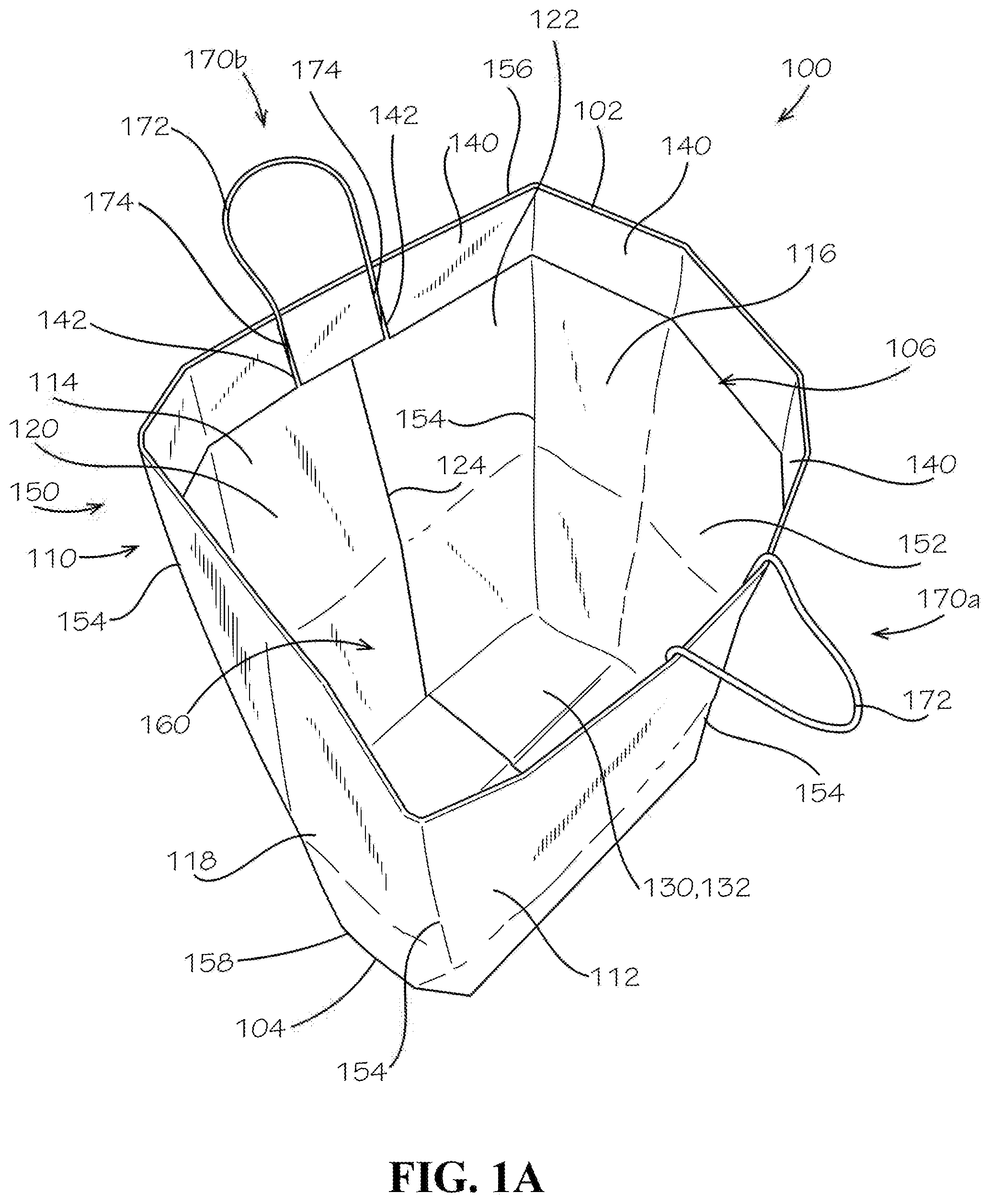
[0010] FIG. 1A is a top perspective view of a lawn refuse bag in an upright, open, and assembled orientation, in accordance with one aspect of the present disclosure.
[0011] FIG. 1B is a detail view of a handle assembly of the lawn refuse bag of FIG. 1.
[0012] FIG. 1C is a top view of the lawn refuse bag of FIG. 1A.
[0013] FIG. 1D is a bottom perspective view of the lawn refuse bag of FIG. 1A.
[0014] FIG. 2 is a bag blank in an unassembled orientation that can be assembled to form the lawn refuse bag of FIG. 1A.
[0015] FIG. 3A is a top perspective view of the lawn refuse bag of FIG. 1A in a partially folded orientation.
[0016] FIG. 3B is a front view of the lawn refuse bag of FIG. 1A in a folded orientation.
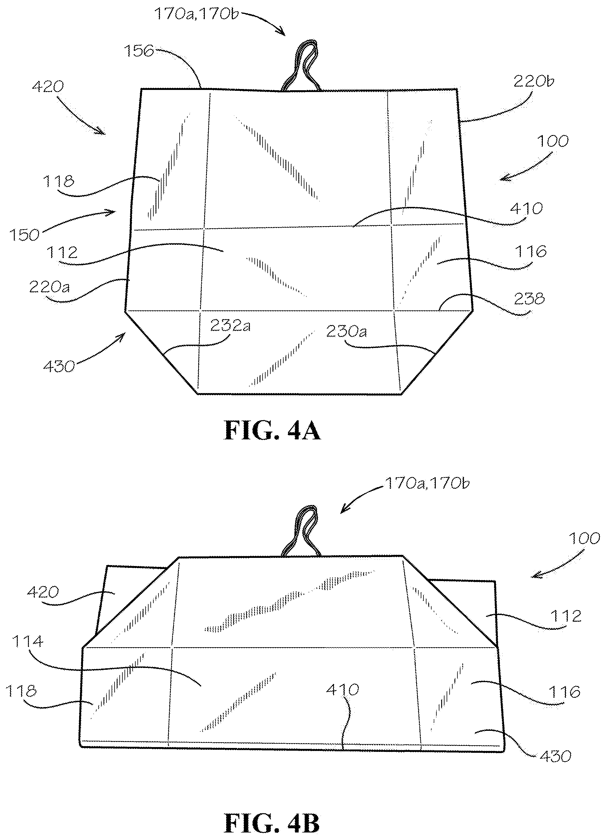
[0017] FIG. 4A is a front view of the lawn refuse in the partially folded orientation, according to another aspect of the present disclosure.
[0018] FIG. 4B is a front view of the lawn refuse bag of FIG. 4A in the folded orientation, according to another aspect of the present disclosure.
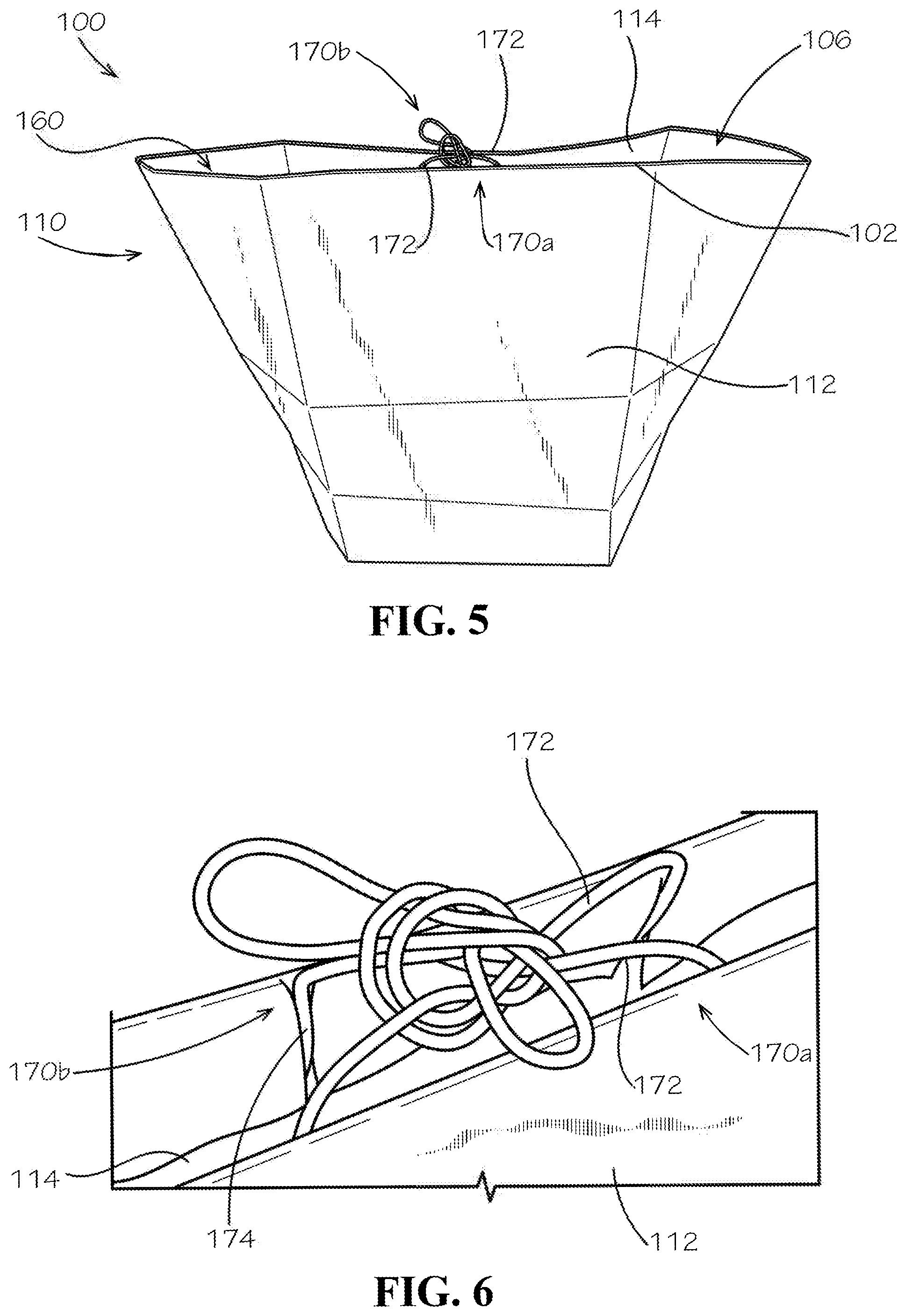
[0019] FIG. 5 is a top perspective view of the lawn refuse bag of FIG. 1A in a closed orientation.
[0020] FIG. 6 is a detail view of a pair of handle assemblies of the lawn refuse bag of FIG. 1A in a tied configuration.
[0021] FIG. 7 is a top perspective view of the lawn refuse bag of FIG. 1A in a sideways orientation.
DETAILED DESCRIPTION
[0022] The present disclosure can be understood more readily by reference to the following detailed description, examples, drawings, and claims, and the previous and following description. However, before the present devices, systems, and/or methods are disclosed and described, it is to be understood that this disclosure is not limited to the specific devices, systems, and/or methods disclosed unless otherwise specified, and, as such, can, of course, vary. It is also to be understood that the terminology used herein is for the purpose of describing particular aspects only and is not intended to be limiting.
[0023] The following description is provided as an enabling teaching of the present devices, systems, and/or methods in its best, currently known aspect. To this end, those skilled in the relevant art will recognize and appreciate that many changes can be made to the various aspects of the present devices, systems, and/or methods described herein, while still obtaining the beneficial results of the present disclosure. It will also be apparent that some of the desired benefits of the present disclosure can be obtained by selecting some of the features of the present disclosure without utilizing other features. Accordingly, those who work in the art will recognize that many modifications and adaptations to the present disclosure are possible and can even be desirable in certain circumstances and are a part of the present disclosure. Thus, the following description is provided as illustrative of the principles of the present disclosure and not in limitation thereof.
[0024] As used throughout, the singular forms "a," "an" and "the" include plural referents unless the context clearly dictates otherwise. Thus, for example, reference to "an element" can include two or more such elements unless the context indicates otherwise.
[0025] Ranges can be expressed herein as from "about" one particular value, and/or to "about" another particular value. When such a range is expressed, another aspect includes from the one particular value and/or to the other particular value. Similarly, when values are expressed as approximations, by use of the antecedent "about," it will be understood that the particular value forms another aspect. It will be further understood that the endpoints of each of the ranges are significant both in relation to the other endpoint, and independently of the other endpoint.
[0026] For purposes of the current disclosure, a material property or dimension measuring about X or substantially X on a particular measurement scale measures within a range between X plus an industry-standard upper tolerance for the specified measurement and X minus an industry-standard lower tolerance for the specified measurement. Because tolerances can vary between different materials, processes and between different models, the tolerance for a particular measurement of a particular component can fall within a range of tolerances.
[0027] As used herein, the terms "optional" or "optionally" mean that the subsequently described event or circumstance can or cannot occur, and that the description includes instances where said event or circumstance occurs and instances where it does not.
[0028] The word "or" as used herein means any one member of a particular list and also includes any combination of members of that list. Further, one should note that conditional language, such as, among others, "can," "could," "might," or "may," unless specifically stated otherwise, or otherwise understood within the context as used, is generally intended to convey that certain aspects include, while other aspects do not include, certain features, elements and/or steps. Thus, such conditional language is not generally intended to imply that features, elements and/or steps are in any way required for one or more particular aspects or that one or more particular aspects necessarily include logic for deciding, with or without user input or prompting, whether these features, elements and/or steps are included or are to be performed in any particular aspect.
[0029] Disclosed are components that can be used to perform the disclosed methods and systems. These and other components are disclosed herein, and it is understood that when combinations, subsets, interactions, groups, etc. of these components are disclosed that while specific reference of each various individual and collective combinations and permutations of these may not be explicitly disclosed, each is specifically contemplated and described herein, for all methods and systems. This applies to all aspects of this application including, but not limited to, steps in disclosed methods. Thus, if there are a variety of additional steps that can be performed it is understood that each of these additional steps can be performed with any specific aspect or combination of aspects of the disclosed methods.
[0030] Disclosed in the present application is a lawn refuse bag and associated methods, systems, devices, and various apparatus. Example aspects of the lawn refuse bag can comprise a bag body defining a top end and a pair of handle assemblies coupled to the bag body at the top end. It would be understood by one of skill in the art that the disclosed refuse bag is described in but a few exemplary aspects among many. No particular terminology or description should be considered limiting on the disclosure or the scope of any claims issuing therefrom.
[0031] FIG. 1A illustrates a first aspect of a lawn refuse bag 100 according to the present disclosure. The lawn refuse bag 100 is depicted in an upright, assembled, and unfolded orientation, such that it is ready for use. As shown, the lawn refuse bag 100 can comprise a bag body 110 and a pair of handle assemblies 170a,170b extending from the bag body 110. Example aspects of the bag body 110 can be formed from a single bag blank 200 (shown in FIG. 2); however, in other aspects, the bag body 110 can be formed from multiple bag blanks. As shown, the bag body 110 can comprise a first end panel, such as a front sidewall panel 112, a second end panel, such as a rear sidewall panel 114, a first sidewall panel, such as a right sidewall panel 116, and a second sidewall panel, such as a left sidewall panel 118. Example aspects of the rear sidewall panel 114 can define a first rear sidewall subpanel 120 and a second rear sidewall subpanel 122 which can be joined together to retain the lawn refuse bag 100 in the assembled orientation, as shown. In various aspects, a joining seam 124 can be formed where the first rear sidewall subpanel 120 can be joined with the second rear sidewall subpanel 122. In other aspects, the joining seam 124 can be formed elsewhere on the side or end panels. For example, in another aspect, the front sidewall panel 112 may define first and second front sidewall subpanels that can be joined together to retain the lawn refuse bag 110 in the assembled orientation and to define the joining seam 124. In another example aspect, the joining seam 124 may be formed between any pair of adjacent panels, such as, for example, between the left sidewall panel 118 and the rear sidewall panel 120.
[0032] According to example aspects, the front sidewall panel 112, rear sidewall panel 114, right sidewall panel 116, and left sidewall panel 118 can define a sidewall enclosure 150 of the bag body 110 in the assembled orientation. An inner sidewall surface 152 of the sidewall enclosure 150 can define an interior cavity 160, as shown, which can be configured to receive lawn refuse (e.g., grass clippings, dirt, sticks, leaves, etc.), as described in further detail below. Example aspects of the sidewall enclosure 150, such as the aspect depicted in FIG. 1A, can define a substantially rectangular cross-section. However, other aspects of the bag body 110 can define any other suitable cross-sectional shape, such as, for example, a square, circle, triangle, pentagon, and the like. As shown, the sidewall enclosure 150 can define four vertical corners 154, relative to the orientation shown, wherein each of the vertical corners 154 can be defined at an intersection of adjacent sidewall panels 112,114,116,118.
[0033] According to example aspects, the bag body 110 can define a top end 102, relative to the orientation shown, at a first end 156 of the sidewall enclosure 150, and a bottom end 104, relative to the orientation shown, at a second end 158 of the sidewall enclosure 150 opposite the first end 156. Example aspects of the bag body 110 can further comprise a base panel, such as a bottom panel 130, positioned at the bottom end 104 of the bag body 110 and oriented about perpendicular to the sidewall panels 112,114,116,118. The bottom panel 130 can extend fully between the sidewall panels 112,114,116,118, such that the bottom end 104 of the bag body 110 can be closed and access to the interior cavity 160 can be prohibited at the bottom end 104. As such, an inner bottom panel surface 132 of the bottom panel 130 can further define the interior cavity 160. However, as shown, the top end 102 of the bag body 110 can define a top opening 106 that can allow access to the interior cavity 160. In the present aspect, the top end 102 of the bag body 110 can be oriented in an open orientation, wherein lawn refuse can be inserted into the interior cavity 160 through the top opening 106 of the bag body 110. The top end 102 of the bag body 110 can also be oriented in a closed orientation, as further shown and described with respect to FIGS. 5 and 6. According to example aspects, in the upright and assembled orientation, as shown, the bottom panel 130 of the lawn refuse bag 100 can be configured to rest on a ground surface (e.g., a lawn or yard). Example aspects of the bottom panel 130 can be substantially flat and can provide suitable dimensions for providing a stable base for the lawn refuse bag 100, which can aid in preventing the lawn refuse bag 100 from tipping over from the desired upright orientation. The lawn refuse bag 100 can further be sized to allow a substantial amount of lawn refuse to be received within the interior cavity 160. Moreover, the top opening 106 of the bag body 110 can be dimensioned to allow a substantially sized cluster of lawn refuse to be inserted therethrough into the lawn refuse bag 100.
[0034] Various example aspects of the bag body 110 can comprise a substantially flexible material, such as paper, as shown. In some aspects, the bag body 110 can comprise a single layer of paper, while in other aspects, the bag body 110 can comprise a double layer of paper. In aspects comprising a double layer of paper, the stiffness and strength of the bag body 110 can be increased. Other aspects of the bag body 110 can comprise any other suitable number of layers. Furthermore, other aspects of the bag body 110 can define any other suitable flexible material, such as, for example, flexible plastic, fabric, or any other suitable flexible material or combination thereof. However, still other aspects of the bag body 110 can define a more rigid material, such as, for example, paperboard, polymer, metal, wood, composite, or any other suitable material or combination thereof. In some aspects, the inner sidewall surface 152 and/or inner bottom panel surface 132 can comprise a coating, such as, for example, a water resistant coating. Other aspects of the lawn refuse bag 100 may not comprise such a coating.
[0035] According to example aspects, each of the handle assemblies 170a,170b can comprise a handle portion 172 and a connection portion 174. The connection portion 174 can be coupled to the lawn refuse bag 100 and the handle portion 172 can extend away from the lawn refuse bag 100, as shown. In the present aspect, each handle assembly 170a,170b can generally define an inverted U-shape, relative to the orientation shown, wherein the connection portion 174 can define the ends of the U-shape and the handle portion 172 can define the middle of the U-shape. As shown, a first one of the handle assemblies 170a can be coupled with the front sidewall panel 112 and a second one of the handle assemblies 170b can be coupled with the rear sidewall panel 114. Referring to the second handle assembly 170b, the connection portion 174 can be secured to the rear sidewall panel 114 to attach the handle assembly 170b to the lawn refuse bag 100, and the handle portion 172 can extend away from the top end 102 of the bag body 110 proximate the top opening 106. The connection portion 174 can be secured to the rear sidewall panel 114 on the inner sidewall surface 152 by a fastener, such as, for example, an adhesive, such as tape or glue. In other aspects, any other suitable type of fastener known in the art can be used. The first handle assembly 170a can be similarly formed and secured to the front sidewall panel 112.
[0036] In example aspects, such as the aspect depicted in FIG. 1A, the handle assemblies 170a,170b can be formed from twisted paper cord. Twisted paper cord can be made from paper that can be tightly twisted, and in some cases can define a crinkle texture, such that the strength and thickness of the paper can be increased. The increased strength and thickness of the handle assemblies 170a,170b can allow the lawn refuse bag 100 to be carried by the handle assemblies 170a,170b even when weighted down by lawn refuse. In other aspects, the handle assemblies 170a,170b can be formed from any other suitable material known in that art having a sufficient strength to allow for carrying the bag in weighted conditions. Furthermore, according to some example aspects, a flexible wire (not shown) or other similar reinforcing structure can extend through each of the handle assemblies 170a,170b to supply additional strength and stiffness to the handle assemblies 170a,170b.
[0037] According to example aspects, one or more top flap segments 140 can extend from the top end 102 of the bag body 110. For example, in the present aspect, each of the sidewall panels 112,114,116,118 can comprise a corresponding top flap segment 140 extending from the first end 156 of the sidewall enclosure 150. Each of the top flap segments 140 can be folded inward about 180.degree. relative to the corresponding sidewall panel 112,114,116,118, such that the top flap segments 140 can lie against the inner sidewall surface 152 of the sidewall enclosure 150. The top flap segments 140 can be secured to the corresponding sidewall panels 112,114,116,118 by a fastener, such as, for example, an adhesive, such as tape or glue. In other aspects, any other suitable fastener known in the art can secure the top flap segments 140 to the inner sidewall surface 152. In some aspects, as shown, one or more slits 142 can be formed in the top flap segments 140 extending from the front and rear sidewall panels 112,114 to accommodate folding the top flap segments 140 around the corresponding handle assemblies 170a,170b. For example, in the present aspect, the corresponding top flap segments 140 can comprise a pair of the slits 142 which can be configured to receive corresponding portions of the corresponding handle assembly 170a,170b therein. In some aspects, the top flap segments 140 of the front and rear sidewall panels 112,114 can partially overlay the corresponding handle assembly 170a,b, and the connection portions 174 can be secured between the top flap segment 140 and the corresponding front or rear sidewall panel 112,114. The second handle assembly 170b is shown and described in further detail with reference to FIG. 1B.
[0038] Furthermore, in some aspects, a first reinforcement strip (not shown) can be received between the bag body 110 and a corresponding one of the top flap segments 140 for granting added structure to the bag body 110 at the top end 102 thereof. Example aspects of the first reinforcement strip can be more rigid that the bag body 110. For example, in a particular aspect, the first reinforcement strip can be a substantially rectangular piece of paperboard. In the present aspect, the first reinforcement strip can be received between the front sidewall panel 112 and the corresponding top flap where the connection portion 174 of the first handle assembly 170a can be attached. As such, the first reinforcement strip can also serve to reinforce the first handle assembly 170a. According to example aspects, a second reinforcement strip (not shown) may also be providing for granting added structure to the rear sidewall panel 114 where the second handle assembly 170b can be attached. Moreover, in other aspects, reinforcement strips may also be provided between each of the right and left sidewall panels 116,118 and the corresponding top flap segments 140.
[0039] In the present aspect, the lawn refuse bag 100 is in an open orientation wherein the top opening 106 can be fully open and access to the interior cavity 160 through the top opening 106 can be unrestricted. The handle assemblies 170a,170b can be disengaged from one another in the open orientation, as shown. According to example aspects, the lawn refuse bag 100 can also be oriented in a closed orientation (shown in FIG. 5), wherein the handle portions 172 of the handle assemblies 170a,170b can be engaged with one another (for example, tied together) to close or partially close the top opening 106 of the lawn refuse bag 100. In the closed orientation, the lawn refuse received within the interior cavity 160 can be prevented from escaping the interior cavity 160 and additional lawn refuse can be prevented from insertion into the interior cavity 160. The closed orientation and the method for tying the handle assemblies 170a,170b together are shown and described in further detail with reference to FIGS. 5 and 6.
[0040] FIG. 1B is a close-up view of the second handle assembly 170b attached to the rear sidewall panel 114 of the lawn refuse bag 100. As shown, the corresponding top flap segment 140 is folded inward to lie against the rear sidewall panel 114 and can partially overlay the connection portions 174. FIG. 1C is top view of the lawn refuse bag 100, illustrating the inner sidewall surface 152 of the sidewall enclosure 150 and the interior cavity 160 for receiving the lawn refuse. The inner bottom panel surface 132 of the bottom panel 130, according to one particular example aspect of the lawn refuse bag 100, is also illustrated. As shown, the bottom panel 130 can be folded to form various bottom panel seams 126 of the bottom panel 130 in the assembled orientation. According to example aspects, the bottom panel 130 can be folded at a plurality of bottom panel bend lines 250 (shown in FIG. 2) to form the bottom panel seams 126. FIG. 1D illustrates an outer bottom panel surface 134 of the bottom panel 130, opposite the inner bottom panel surface 132 (shown in FIG. 1A), according to one particular example aspect of the lawn refuse bag 100. The various bottom panel seams 126 of the bottom panel 130 in the assembled orientation are also shown.
[0041] FIG. 2 illustrates the bag blank 200 for forming the lawn refuse bag 100 (shown in FIG. 1A) in an unassembled orientation. Various dimensions for the bag blank 200 are shown in inches, according to an example aspect of the present disclosure. The dimensions disclosed herein are merely examples and should not be construed as limiting. As shown, the bag blank 200 can be a single, continuous blank defining a first blank end, such as a left blank end 202, relative to the orientation shown, and an opposite second blank end, such as a right blank end 204, relative to the orientation shown. Each of the sidewall panels 112,114,116,118 can be connected to adjacent sidewall panels 112,114,116,118 by a corner bend line 210, and the corner bend lines 210 can define the vertical corners 154 (shown in FIG. 1A) in the assembled orientation (shown in FIG. 1A). For example, the first rear sidewall subpanel 120 of the rear sidewall panel 114 can be connected to the left sidewall panel 118 by a first corner bend line 210a, the left sidewall panel 118 can be connected to the front sidewall panel 112 by a second corner bend line 210b, the front sidewall panel 112 can be connected to the right sidewall panel 116 by a third corner bend line 210c, and the right sidewall panel 116 can be connected to the second rear sidewall subpanel 122 of the rear sidewall panel 114 by a fourth corner bend line 210d.
[0042] Each of the left sidewall panel 118 and right sidewall panel 116 can also comprise a vertical center bend line 220a,b, respectively, relative to the orientation shown, extending along a centerline thereof. The center bend lines 220a,b can facilitate folding of the lawn refuse bag 100, as described in further detail with reference to FIG. 3A. Additionally, the bag blank 200 can define a horizontal bend line 238, relative to the orientation shown, that can extend across the sidewall panels 112,114,116,118 about perpendicular to the corner bend lines 210a,b,c,d and center bend lines 220a,b. As shown, the bend line 238 can be oriented between the first end 156 of the sidewall enclosure 150 and the second end 158 of the sidewall enclosure 150. Moreover, each of the left sidewall panel 118 and right sidewall panel 116 can define a pair of opposing angled bend lines 230a,b and 232a,b, respectively. For example, referring to the left sidewall panel 118, a first one of the angled bend lines 230a can extend at about a 45.degree. angle between the corresponding center bend line 220a the intersection of the left sidewall panel 118 with the bottom panel 130 and the first rear sidewall subpanel 120. A second one of the angled bend lines 230b can extend at about a 45.degree. angle between the center bend line 220a and the intersection of the left sidewall panel 118 with the bottom panel 130 and the front sidewall panel 112. As such, the pair of angled bend lines 230a,b can substantially define an inverted V-shape, wherein an apex of the inverted V-shape can intersect the horizontal bend line 238, as shown. The angled bend lines 232a,b of the right sidewall panel 116 can be similarly formed. The pairs of angled bend lines 230a,b and 232a,b and the bend line 238 can further aid in folding the lawn refuse bag 100, as described in further detail with reference to FIG. 3B. In the present aspect, the various bend lines of the bag blank 200 can be formed by a crease; however, in other aspects, some or all of the bend lines can be formed by a perforation, a series of perforations, or any other suitable arrangement configured to weaken the area of the bend line to facilitate bending along the bend line.
[0043] As shown, the top flap segments 140 can be formed as a single strip of material extending fully along the length of the sidewall enclosure 150 from the left blank end 202 to the right blank end 204. The top flap segments 140 can be divided from one another by the corresponding corner bend lines 210a,b,c,d. Furthermore, the top flap segments 140 can be connected to the first end 156 of the sidewall enclosure 150 by a top flap bend line 234. The bottom panel 130 can also extend along fully along the length of the sidewall enclosure 150 from the left blank end 202 to the right blank end 204, and can be connected to the second end 158 of the sidewall enclosure 150 by a bottom panel bend line 236. A first fastening flap, such as a left fastening flap 240, relative to the orientation shown, can be formed at the left blank end 202 and can extend along the first rear sidewall subpanel 120, the corresponding top flap segment 140, and the bottom panel 130. A second fastening flap, such as a right fastening flap 242, relative to the orientation shown, can be formed at the right blank end 204 and can extend along the second rear sidewall subpanel 122, the corresponding top flap segment 140, and the bottom panel 130. A first step in assembling the lawn refuse bag 100 from the blank can comprise overlapping and securing the left fastening flap 240 to the right fastening flap 242, which can define the joining seam 124 (shown in FIG. 1A) in the assembled orientation.
[0044] According to example aspects, a second step in assembling the lawn refuse bag 100 can comprising folding the bottom panel 130 and securing the bottom panel 130 in the folded configuration. As shown, multiple bottom panel bend lines 250 can be provided to facilitate folding the bottom panel 130 into the orientation substantially perpendicular to the sidewall enclosure 150 in the assembled orientation (shown in FIG. 1A). As shown, the bottom panel 130 can also comprise one or more base panel attachment regions, such as bottom panel attachment regions 252, that can be secured the lawn refuse bag 100 (e.g., to each other and/or other portions of the bottom panel 130) to retain the bottom panel 130 in the folded configuration of the assembled orientation, and to form the bottom panel seams 126 (shown in FIGS. 1C and 1D). The bottom panel attachment regions 252 can be secured in the folded configuration by a fastener, such as, for example, an adhesive, such as glue or tape. In other aspects, the first and second steps for assembling the lawn refuse bag 100 can be performed in reverse order.
[0045] FIG. 3A illustrates the lawn refuse bag 100 in a partially folded orientation. As shown, the lawn refuse bag 100 can be folded along the center bend lines 220a,b of the left sidewall panel 118 and right sidewall panel 116, respectively. In folding the lawn refuse bag 100 along the center bend lines 220a,b, the front sidewall panel 112 and rear sidewall panel 114 can be drawn towards one another, closing or partially closing the top opening 106 at the top end 102 of the bag body 110. FIG. 3B illustrates the lawn refuse bag 100 in a fully folded orientation. The lawn refuse bag 100 can be folded along the angled bend lines 230a,b of the left sidewall panel 118 and the angled bend lines 232a,b of the right sidewall panel 116. The lawn refuse bag 100 can then be further folded along the bend line 238, such that at least a portion of the bottom panel 130 of the lawn refuse bag 100 can be folded to lie substantially flat against the rear sidewall panel 114, as shown. In other aspects, the at least a portion of the bottom panel 130 can be folded to lie substantially flat against the front sidewall panel 112 (shown in FIG. 1).
[0046] FIGS. 4A and 4B illustrate another example method of folding another aspect of the lawn refuse bag 100. As shown in FIG. 4A, the lawn refuse bag 100 can be folded in a similar manner to the folded lawn refuse bag 100 shown in FIGS. 3A and 3B. Example aspects of the current lawn refuse bag 100 can also comprise an additional bend line 410 extending horizontally, relative to the orientation shown, across the sidewall panels 112,114,116,118 (rear sidewall panel 114 shown in FIG. 1). The bend line 410 can be oriented between the bend line 238 and the first end 156 of the sidewall enclosure 150, and can be substantially perpendicular to the same. The bend line 410 can also generally define an upper region 420 and an opposite lower region 430 of the lawn refuse bag 100. As shown in FIG. 4B, the lawn refuse bag 100 can further be folded at the bend line 410, such that the lower region 430 of the lawn refuse bag 100 can lie substantially flat against the upper region 420 of the lawn refuse bag 100 to further reduce the footprint of the folded lawn refuse bag 100.
[0047] FIG. 5 illustrates the top end 102 of the bag body 110 in a closed orientation. In the closed orientation, the top end 102 of the bag body 110 can be fully closed or can be partially closed, as shown. As shown, in the closed orientation, the handle portion 172 of the first handle assembly 170a can be tied together with the handle portion 172 of the second handle assembly 170b. For example, in the present aspect, the handle portions 172 can be tied together in the fashion of a double knot, such that the handle portions 172 can be retained in a tied configuration. However, in other aspects, the handle portions 172 can be tied together in a single knot or in any other suitable fashion that can retain the handle portions 172 in the tied configuration. When the handle portions 172 are tied together, the front sidewall panel 112 and rear sidewall panel 114 can be drawn together at the top end 102 of the bag body 110, and the top opening 106 of the bag body 110 can be closed or partially closed, as shown. As such, in the closed orientation, the lawn refuse received within the interior cavity 160 can be restricted from escaping the interior cavity 160 and additional lawn refuse can be prevented from insertion into the interior cavity 160. FIG. 6 is a detail view of the handle assemblies 170a,170b in the tied configuration.
[0048] As such, an example method for using the lawn refuse bag 100 can comprising providing the lawn refuse bag 100 comprising the bag body 110, the first handle assembly 170a, and the second handle assembly 170b, wherein the bag body 110 defines the interior cavity 160 and the top end 102, and the top end 102 defines the top opening 106. The method can further comprise inserting lawn refuse into the interior cavity 160 through the top opening 106 and then tying the handle portion 172 of the first handle assembly 170a with the handle portion 172 of the second handle assembly 170b to orient the top end 102 of the lawn refuse bag 100 in the closed orientation. To insert the lawn refuse into the lawn refuse bag 100, a cluster of the lawn refuse can be shifted (e.g., scooped, shoveled, etc.) from the lawn or yard into the interior cavity 160 manually or using a tool, such as, for example a rake. In one aspect, the lawn refuse bag 100 can be oriented in the upright orientation, as shown in FIG. 1A, wherein the bottom panel 130 of the bag body 110 is configured to lie on a ground surface (e.g., the yard, lawn, etc.). The lawn refuse can be scooped up off of the ground surface and dumped into the interior cavity 160. This process can be repeated until the lawn refuse bag 100 is full or until all of the lawn refuse is received within the lawn refuse bag 100, whichever comes first. In some aspects, the method can further comprise unfolding the lawn refuse bag 100 from a folded orientation to an unfolded orientation. The method may also comprise opening the top end 102 of the lawn refuse bag to orient the top end 102 in an open orientation prior to inserting the lawn refuse therein. Additional aspects can further comprise assembling the bag blank 200 to form the lawn refuse bag 100.
[0049] Referring to FIG. 7, in other aspect, the lawn refuse bag 100 can be oriented in a sideways orientation, as shown. According to example aspects, in the sideways orientation, the rear sidewall panel 114 of the bag body 110 can be configured to lie on the ground surface. In other aspects, any of the front sidewall panel 112, right sidewall panel 116, and left sidewall panel 118 can be configured to lie on the ground surface in the sideways orientation. According to example aspects, with the lawn refuse bag 100 in the sideways orientation, the lawn refuse can be shoveled directly from the ground surface into the interior cavity 160 through the top opening 106, which can be oriented adjacent to the ground surface. In some aspects, the one or more reinforcement strips can provide added structure to the lawn refuse bag 100 to prevent the front sidewall panel 112 from collapsing towards the rear sidewall panel 114 and to maintain the top opening 106 in the open orientation. In still other aspects, as depicted, a refuse bag insert 700 may be provide for providing additional structure to the lawn refuse bag 100.
[0050] One should note that conditional language, such as, among others, "can," "could," "might," or "may," unless specifically stated otherwise, or otherwise understood within the context as used, is generally intended to convey that certain embodiments include, while other embodiments do not include, certain features, elements and/or steps. Thus, such conditional language is not generally intended to imply that features, elements and/or steps are in any way required for one or more particular embodiments or that one or more particular embodiments necessarily include logic for deciding, with or without user input or prompting, whether these features, elements and/or steps are included or are to be performed in any particular embodiment.
[0051] It should be emphasized that the above-described embodiments are merely possible examples of implementations, merely set forth for a clear understanding of the principles of the present disclosure. Any process descriptions or blocks in flow diagrams should be understood as representing modules, segments, or portions of code which include one or more executable instructions for implementing specific logical functions or steps in the process, and alternate implementations are included in which functions may not be included or executed at all, may be executed out of order from that shown or discussed, including substantially concurrently or in reverse order, depending on the functionality involved, as would be understood by those reasonably skilled in the art of the present disclosure. Many variations and modifications may be made to the above-described embodiment(s) without departing substantially from the spirit and principles of the present disclosure. Further, the scope of the present disclosure is intended to cover any and all combinations and sub-combinations of all elements, features, and aspects discussed above. All such modifications and variations are intended to be included herein within the scope of the present disclosure, and all possible claims to individual aspects or combinations of elements or steps are intended to be supported by the present disclosure.
* * * * *
D00000
D00001
D00002
D00003
D00004
D00005
D00006
D00007
D00008
XML
uspto.report is an independent third-party trademark research tool that is not affiliated, endorsed, or sponsored by the United States Patent and Trademark Office (USPTO) or any other governmental organization. The information provided by uspto.report is based on publicly available data at the time of writing and is intended for informational purposes only.
While we strive to provide accurate and up-to-date information, we do not guarantee the accuracy, completeness, reliability, or suitability of the information displayed on this site. The use of this site is at your own risk. Any reliance you place on such information is therefore strictly at your own risk.
All official trademark data, including owner information, should be verified by visiting the official USPTO website at www.uspto.gov. This site is not intended to replace professional legal advice and should not be used as a substitute for consulting with a legal professional who is knowledgeable about trademark law.