Patient's Skin-puncturing Devices
GRZELAK; Robert ; et al.
U.S. patent application number 16/643404 was filed with the patent office on 2021-03-11 for patient's skin-puncturing devices. The applicant listed for this patent is HTL-STREFA S.A.. Invention is credited to Robert GRZELAK, Jacek KARBOWNICZEK, Marcin KOMUDA, Marcin NIEMIEC, Marcin ROZWADOWSKI.
| Application Number | 20210068728 16/643404 |
| Document ID | / |
| Family ID | 1000005253005 |
| Filed Date | 2021-03-11 |


View All Diagrams
| United States Patent Application | 20210068728 |
| Kind Code | A1 |
| GRZELAK; Robert ; et al. | March 11, 2021 |
PATIENT'S SKIN-PUNCTURING DEVICES
Abstract
The device is comprised of oblong main body and the cup, which locks the front end of the main body. A casing of the main body is shaped as a tube. A puncture mechanism with a lancet leading unit, a puncture depth regulation mechanism and used lancet removal mechanism are installed in the casing. They compose a mechanism unit, which components are installed in a mechanism body, fastened inside the casing. The lancet leading mechanism is comprised of a lancet socket with guide, that goes through the opening in the transversal partition of the mechanism body, and lancet chamber. The guide is linked with the front end of a driving sleeve, sliding and rotary fitted in the mechanism body. Between the transversal partition and the driving sleeve there is the return spring. Between the driving sleeve and a button there is the drive spring. At the end of the casing there is the button, sliding and rotary fitted. The tension in the drive spring is released by a springy latch of the driving sleeve, that cooperates with a stop surface of the mechanism body and an activating surface of the button. The puncture depth regulation mechanism is comprised of the button rotary coupled with the driving sleeve and limiting steps limiting the movement of a bumper of the driving sleeve.
| Inventors: | GRZELAK; Robert; (Ozorkow, PL) ; ROZWADOWSKI; Marcin; (Ozorkow, PL) ; KARBOWNICZEK; Jacek; (Ozorkow, PL) ; KOMUDA; Marcin; (Ozorkow, PL) ; NIEMIEC; Marcin; (Ozorkow, PL) | ||||||||||
| Applicant: |
|
||||||||||
|---|---|---|---|---|---|---|---|---|---|---|---|
| Family ID: | 1000005253005 | ||||||||||
| Appl. No.: | 16/643404 | ||||||||||
| Filed: | September 1, 2018 | ||||||||||
| PCT Filed: | September 1, 2018 | ||||||||||
| PCT NO: | PCT/PL2018/050046 | ||||||||||
| 371 Date: | February 28, 2020 |
| Current U.S. Class: | 1/1 |
| Current CPC Class: | A61B 5/150022 20130101; A61B 5/150503 20130101; A61B 5/15194 20130101; A61B 5/15117 20130101; A61B 5/15113 20130101; A61B 5/150412 20130101; A61B 5/1513 20130101; A61B 5/15019 20130101 |
| International Class: | A61B 5/151 20060101 A61B005/151; A61B 5/15 20060101 A61B005/15 |
Foreign Application Data
| Date | Code | Application Number |
|---|---|---|
| Sep 2, 2017 | PL | P.422730 |
Claims
1. A skin puncturing device, which is comprised of oblong main body, a cup closing the front end of the main body, placed against patient's skin and which has an opening for the puncturing a lancet blade, a puncturing mechanism with a lancet guiding mechanism, a drive spring of the lancet guiding mechanism, return spring of the lancet guiding mechanism, a button for tensioning the drive spring in the back part of the main body with a member releasing the drive spring tension as well as having a puncture depth regulation mechanism and a used lancet removal mechanism, characterized in that the main body have a casing in form of a tube with longitudinal axis as well as front and back ends opened, while the puncturing mechanism, the puncture depth regulation mechanism and the used lancet removal mechanism form the mechanism unit installed inside the main body, elements of the mechanism unit are placed inside the mechanism body, permanently fixed inside the casing, the front end of the mechanism body is generally flush with the front end of the casing its back end is located inside the casing, the lancet guiding mechanism is comprised of the lancet socket with oblong guide that passes through the opening in the transverse partition of the mechanism body and finished in the front end with the lancet chamber, which in the back end is linked with the front end of the driving sleeve, the driving sleeve is rotary and sliding fitted in the back part of the mechanism body, the return spring is placed between the transverse partition and the end of the driving sleeve, linked with guide of the lancet socket, the drive spring is placed between the driving sleeve and the button, the button is rotary and sliding fitted in the back end of the casing, the member releasing the drive spring tension is a springy latch of the driving sleeve, cooperating with a stop surface of the mechanism body and an activating surface of the button, whereas the puncture depth regulation mechanism is comprised of the button rotary coupled with the driving sleeve and of limiting steps limiting the movement of bumper of the driving sleeve.
2. The puncturing device according to claim 1, characterized in that the button is equipped with at least one latch, defining a sequence of angular positions of the button upon its rotation in relation to the casing and a sequence of anti-rotary channels, placed opposite the oblong fin of the mechanism body in any angular position of the button defined by the latch, whereas the button is linked with two side sliders, sliding fitted inside channels of the mechanism body, front latches of the side sliders reach inside the mechanism body, inside the mechanism body a driver setting is rotary fitted, in which the driver with notches for the front latches of the side sliders is sliding fitted in the axial direction, whereas the cup has a longitudinal channel for the lancet chamber, elements of the bayonet connector that cooperate with other components of the bayonet connector placed in the front part of the main body and at least one fin coupling the cup with the driver setting.
3. The puncturing device according to claim 1, characterized in that the used lancet removal mechanism is comprised of an ejector fitted sliding on the guide of the lancet socket between the lancet chamber and the driver, the throughfeed window for the ejector in the bottom of the lancet chamber, the button, the driving sleeve, the return spring and of the driver.
4. The puncturing device according to claim 1, characterized in that the cup is comprised of a cup sheath and a cup base permanently fixed inside of the sheath, whereas the axial channel, components of the bayonet fitting and at least one fin are integral elements of the cup base.
5. The puncturing device according to claim 2, characterized in that it is equipped with angular position indicator of the button in relation to the casing.
6. The puncturing device according to claim 5, characterized in that the angular position indicator of the button is a sequence of symbols of a consecutive angular positions of the button, located circumferentially on its side surface and a window in the casing, located above the said symbols on the released button.
7. The puncturing device according to claim 1, characterized in that the end of the button that protrudes from the casing and the cup have surfaces for the user's fingers, indicated with curvature change of the outer surface of the button and of the cup, whereas the outer surface of the casing has an elevated shape for improved gripping.
Description
[0001] The subject of the invention is the patient's skin puncturing device, which is designed especially for blood sampling.
[0002] Puncturing devices, equipped with disposable lancets, designed to puncture human skin in order to sample a drop of capillary blood for medical tests, for instance level of glucose, are known and widely used. Most of these devices are comprised of casing and lancet cover, lancet carrier, loading mechanism that loads one of the springs, activating mechanism that releases the loaded spring and lever or slide that pushes the lancet out. Lancet is launched from retracted position, from within the device ahead, to the position where only a fragment of the lancet needle pokes out of the front surface, which is put against the skin. Some devices of this sort have a puncture depth regulation mechanism. The key feature of the puncturing device is simplicity of use and handling comfort, because older diabetic patients, who might have problems with sight and firm grip, are the biggest group of users of such devices. Therefore, the construction of such devices aims to create shape and manner of operating similar to a typical pen, thus a device of proven, simple and intuitive shape, well known to everyone.
[0003] In the descriptions of European patents no. EP2375985 and EP2375986 two types of patient's skin puncturing devices were disclosed, equipped with oblong body, shut from the front with a cup, from which the lancet blade protrudes, drive spring and return spring, puncture depth regulating mechanism with regulation wheel at the back of the body, side slider that loads the drive spring and side button that releases the spring.
[0004] In publication WO 2013/155052 a puncturing device similar to a pen was disclosed, equipped with drive spring, return spring, spring loading button at the back of the device body, front cup, from which the lancet blade protrudes, side button releasing the spring and side slider ejects the used lancet.
[0005] The goal of the invention was to develop a construction of the patient's skin puncturing device with a minimized number of elements controlling the device.
[0006] This goal is met by a device according to the invention, equipped with oblong main body and a cup closing the front end of the main body, with an opening for puncturing lancet blade, put to the patient's skin. This device further comprises a puncturing mechanism with a lancet leading unit, drive spring of the lancet guiding unit, return spring of the lancet guiding unit, button for loading the drive spring at the back of the main body and triggering member releasing the drive spring, as well as a mechanism adjusting the puncture depth and mechanism for ejecting the used lancet. The invention consists of that the main body of the device has a casing in form of a tube with longitudinal axis as well as with open front and back end. The puncturing mechanism, the puncture depth regulation mechanism and used lancet removal mechanism constitute the mechanism unit, located inside the main body. The elements of the mechanism unit are placed in mechanism body, fitted immovably inside the casing. The mechanism body has the front end, generally flush with the front end of the body and the back end, located inside of the body. The lancet guiding unit is comprised of a lancet socket with oblong guide that passes through an opening in the cross partition of the mechanism body and a lancet chamber in the front. At the back end, the guide is connected with the front end of a driving sleeve. The driving sleeve is mounted rotary and sliding in the back end of the mechanism body. The return spring is located between the transverse partition of the mechanism body and the end of the driving sleeve, which is connected with the lancet socket guide. The drive spring is located between the driving sleeve and the button. The button is sliding and rotary fitted in the back of the casing. The triggering member the mainspring is a springy latch of the drive sleeve that cooperates with stop surface of the mechanism body and activating surface of the button. The puncture depth regulation mechanism is comprised of a button rotary coupled with the driving sleeve and limiting steps limiting the movement of the bumper of the driving sleeve.
[0007] In one of variants of the invention, the button is equipped with at least one catch, defining the sequence of angular positions of the button during its rotation against the body and a sequence of anti-rotary notches opposite of the longitudinal fin of the mechanism body in every angular position of the button, defined by the catch. The button is linked to two sliders, fitted sliding inside channels of the mechanism body, whereby the front latches of the side sliders reach into the mechanism body. In the inner part of the mechanism body there is a rotary fitted setting of inner driver, in which the driver is fitted sliding longitudinally, with notches for front latches of the side sliders. The cup has a longitudinal channel for the lancet chamber, bayonet connector elements of the cup cooperating with elements of the bayonet connector in the front part of the main body and at least one coupling fin with the setting of driver. The next variant of the invention, the used lancet removal mechanism is comprised of ejector fitted sliding on the lancet socket guide between the lancet chamber and the driver, and throughfeed window for ejector, located at the bottom of the lancet chamber, button, driving sleeve, return spring and driver.
[0008] In another variant of the invention, the cup is comprised of the cup sheath and immovable cup base fitted in the cup sheath, while the longitudinal channel, elements of the bayonet connector and at least one fin are the integral parts of the cup base.
[0009] In next variant of the invention, the device is equipped with indicator of selected angular position of the button in relation to the casing.
[0010] In another variant of the invention, the selected angular position indicator of the button is a sequence of symbols of the angular positions of the button, located circumferentially on the side surface and a window in the body, located above the said symbols on the button in its released state.
[0011] In another variant of the invention the end of the button protruding from the body and the cup, have a surface for the operator's finger, indicated by the change of the outer curvature of the button and the cup surface, whereas the outer surface of the body has an elevated shape improving operator's grip.
[0012] The device, according to the invention, might be used with single hand and it has only two elements that the user shall interact with, namely the button at the end of the body and the cup at the front side of the body. In order to perform the puncture, the operator only has to use one finger, to push the button. After releasing the button, the device is ready to perform another puncture. The possibility of an accidental puncture occurring is minimized when the cup is not fitted, which definitely increases the safety of the user while changing the lancet. Only one outer element is movable, i.e. the button, which radically minimizes the possibility of damage by breaking, tearing off or falling out of any element. Tight casing with minimized number of slits helps keeping the device clean. One distinct actuator, that is the button, simplifies the personalization with application of button in various colors.
[0013] The invention, shown in the figures of drawing as the exemplary embodiment, but scale between the figures is not kept.
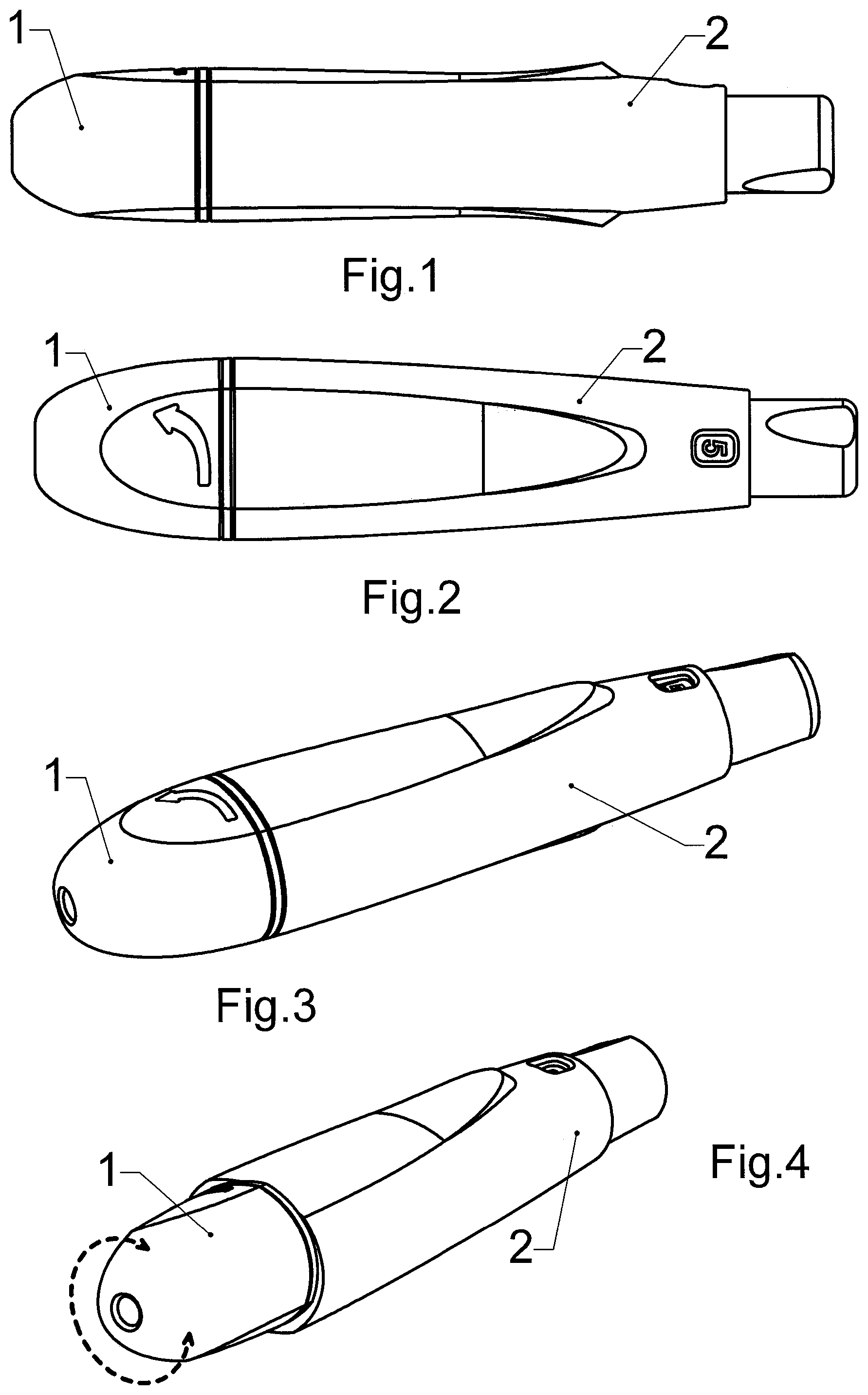
[0014] FIG. 1 and FIG. 2 present the device from the side and from the top respectively.
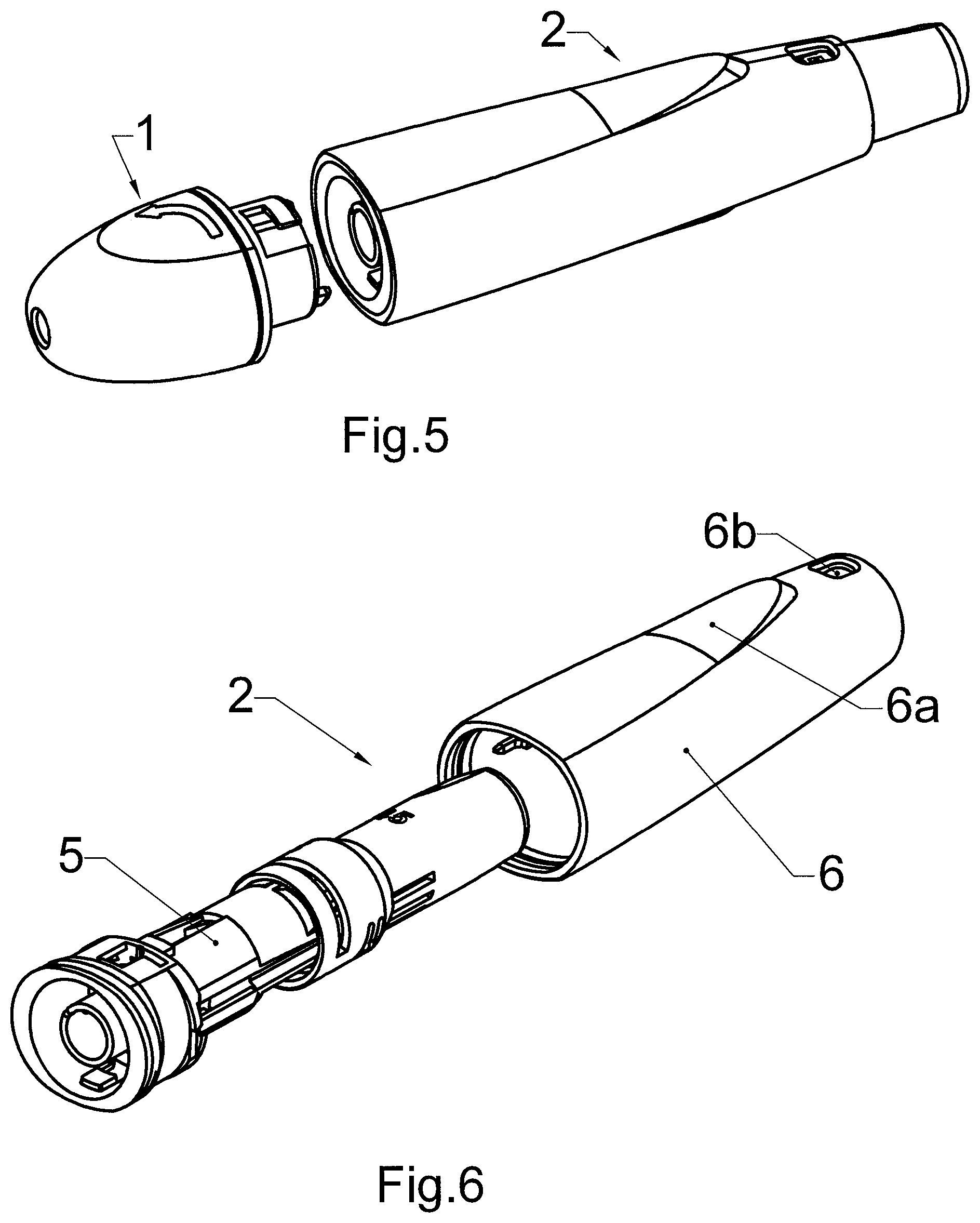
[0015] FIG. 3, FIG. 4 and FIG. 5 present axonometric views of the device with the cup assembled, rotated and removed respectively.
[0016] FIG. 6 presents axonometric view of the casing of the main body and the mechanism unit installed in the casing.
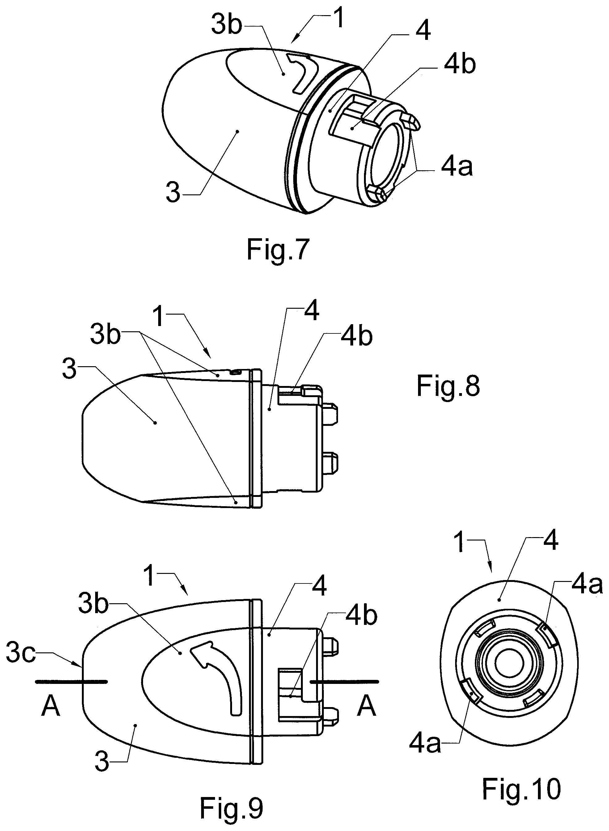
[0017] FIG. 7 presents the axonometric view of the cup of the device;
[0018] FIG. 8, FIG. 9 and FIG. 10 present the cup from the side, from the top and from the back respectively.
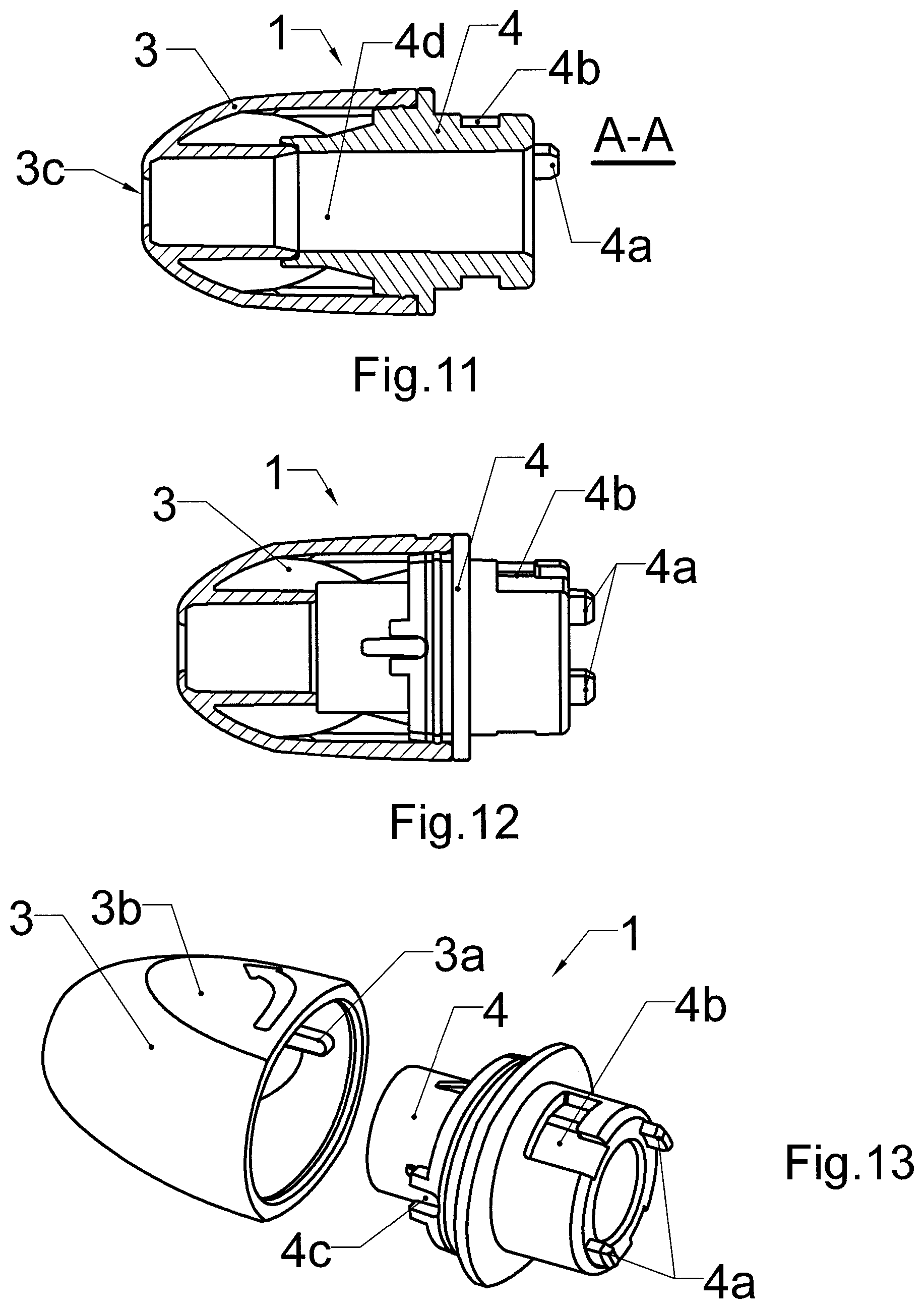
[0019] FIG. 11 presents longitudinal section of the cup presented in FIG. 8 while FIG. 12 presents longitudinal section of the same cup sheath.
[0020] FIG. 13 presents the components of the cup from FIG. 7 that is its sheath and base.
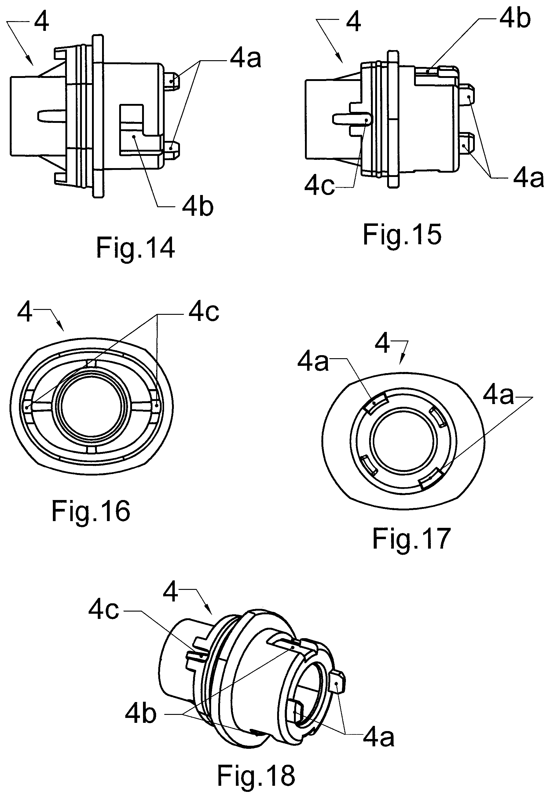
[0021] FIG. 14 and FIG. 15 present the base of the cap from the top and from the back respectively.
[0022] FIG. 16, FIG. 17 and FIG. 18 present the cap from the top, from the back and in axonometric view respectively.
[0023] FIG. 19 presents so-called exploded-view drawing of the mechanism unit,
[0024] FIG. 20 presents the longitudinal section of the main body, and
[0025] FIG. 21 presents axonometric view of the assembled mechanism unit from FIG. 19, with removed button and in partial cross-section.
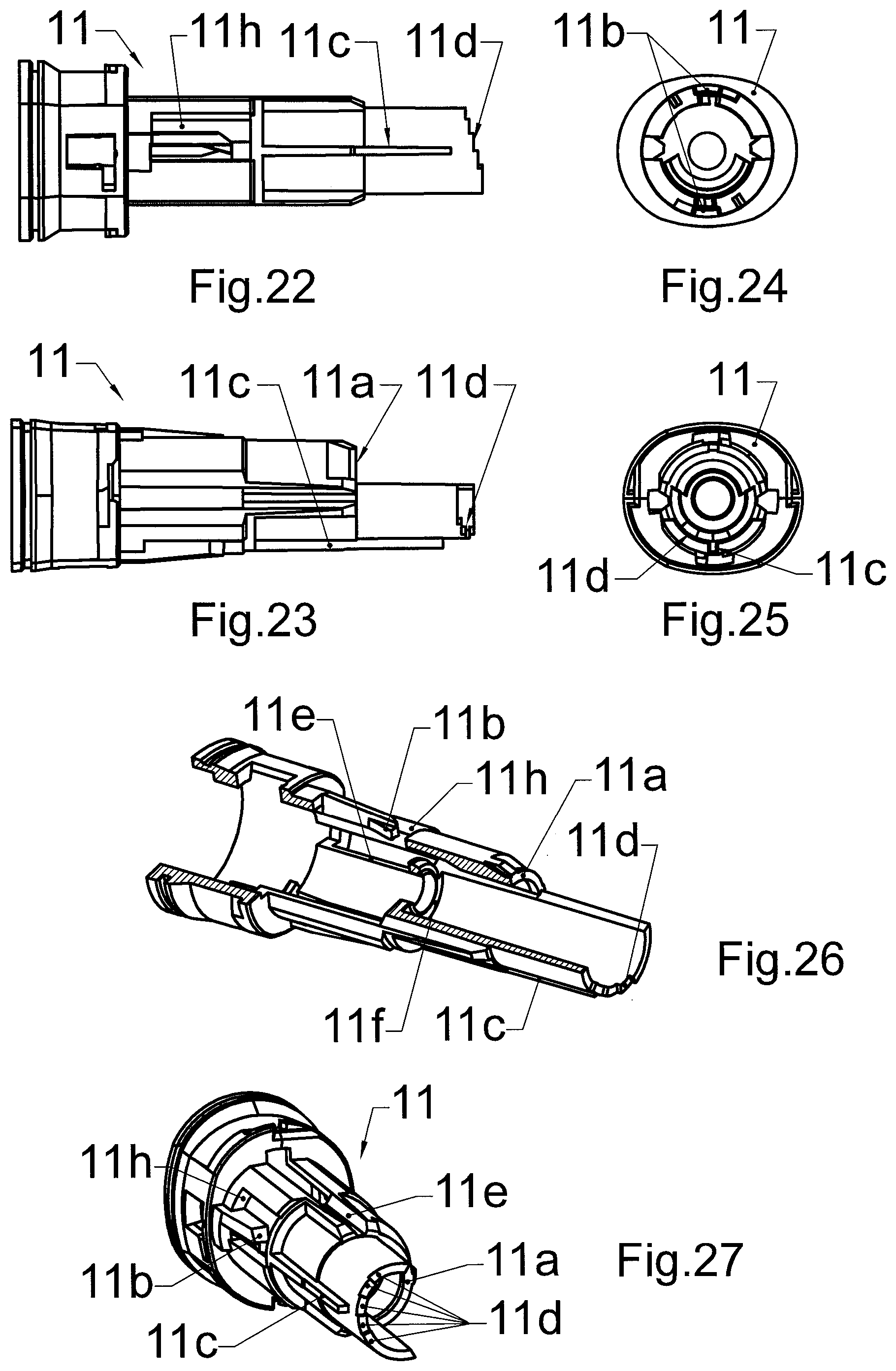
[0026] FIG. 22, FIG. 23, FIG. 24 and FIG. 25 present the mechanism body from below, from the side, from the front and from the back respectively.
[0027] FIG. 26 presents the axonometric view of the mechanism body with partial cross-section while FIG. 27 presents another axonometric view of the mechanism body.
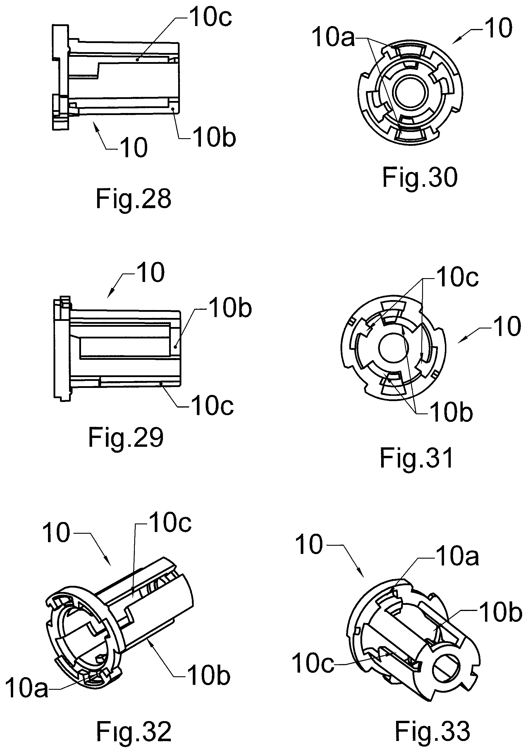
[0028] FIG. 28 and FIG. 29 present the setting of driver in two separate views from the sides,
[0029] FIG. 30 and FIG. 31 present the same setting from the front and from the back respectively,
[0030] FIG. 32 and FIG. 33 present the setting in axonometric views from the front and from the back respectively.
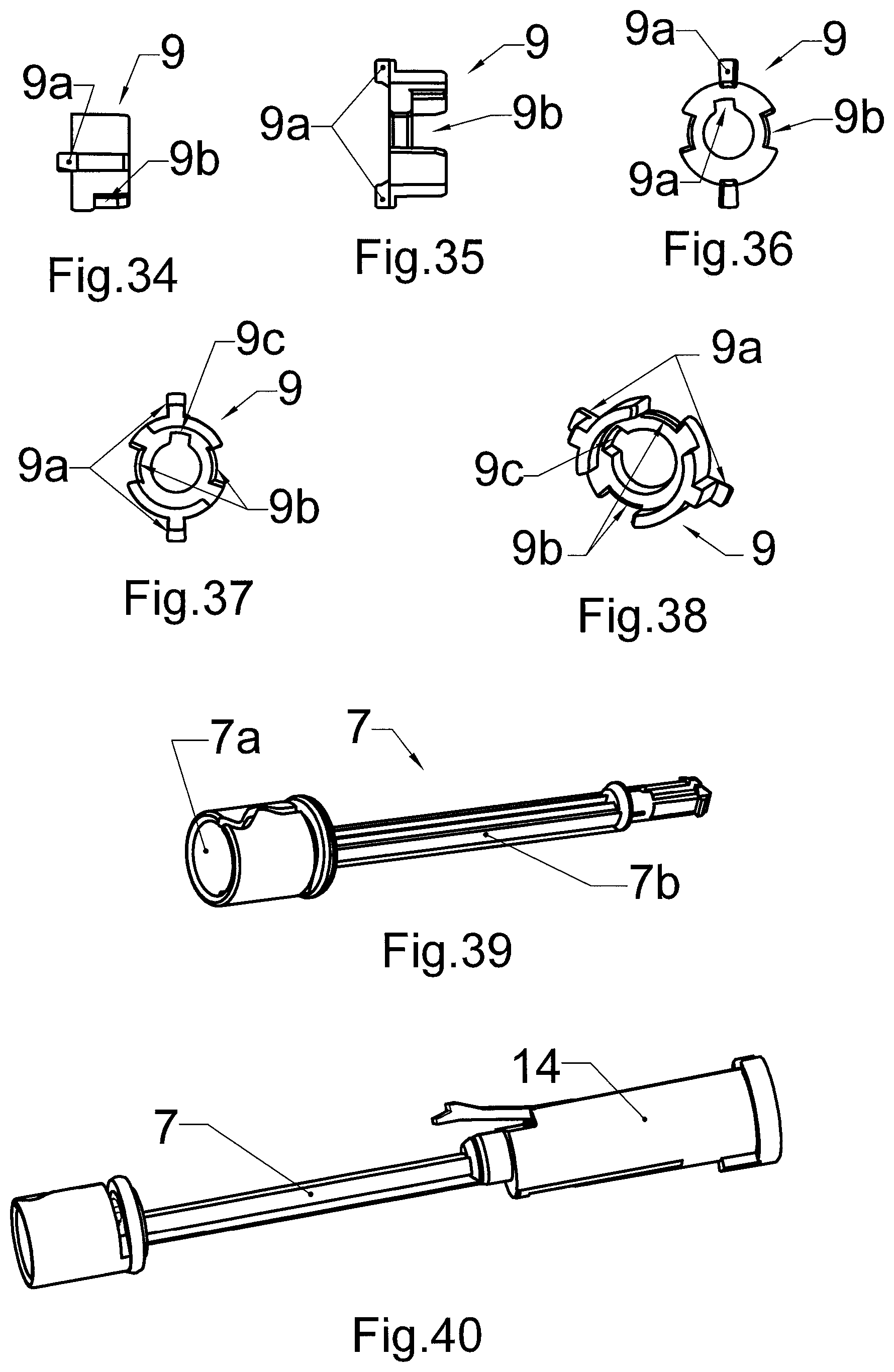
[0031] FIG. 34 and FIG. 35 present the driver in two different views from the sides,
[0032] FIG. 36 and FIG. 37 present the driver from the back and from the front respectively,
[0033] FIG. 38 presents the driver in axonometric view.
[0034] FIG. 39 presents the axonometric view of the lancet socket,
[0035] FIG. 40 presents the axonometric view of the lancet socket linked with the driving sleeve.
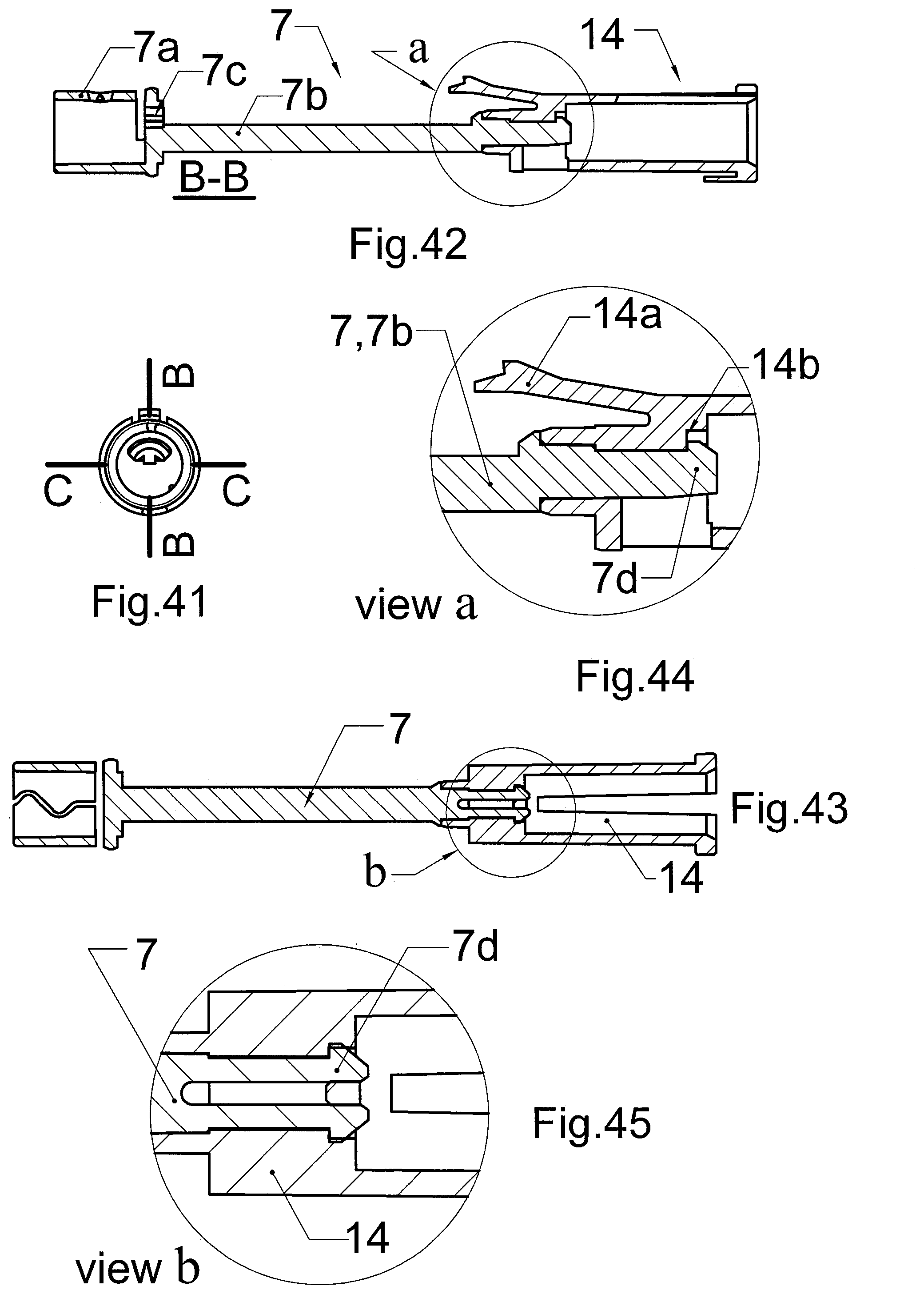
[0036] FIG. 41 presents the lancet socket from the front, with two cut surfaces,
[0037] FIG. 42 presents the cross-section of the unit of FIG. 40 in cross-section, using one of the planes of FIG. 41, and
[0038] FIG. 43 presents the cross-section of the same unit, using the second plane of FIG. 41.
[0039] FIG. 44 presents an enlarged fragment of the cross-section shown in the FIG. 42 and
[0040] FIG. 45 presents an enlarged fragment of the cross-section shown in the FIG. 43.
[0041] FIG. 46, FIG. 47 and FIG. 48 present the driver sleeve shown in FIG. 40 from the side, from below and from the front respectively.
[0042] FIG. 49 presents lancet ejector from the side and FIG. 50 presents the same lancet ejector from the top.
[0043] FIG. 51 and FIG. 52 present the ejector in axonometric views from the top and from below respectively.
[0044] FIG. 53 presents lancet socket with ejector fitted.
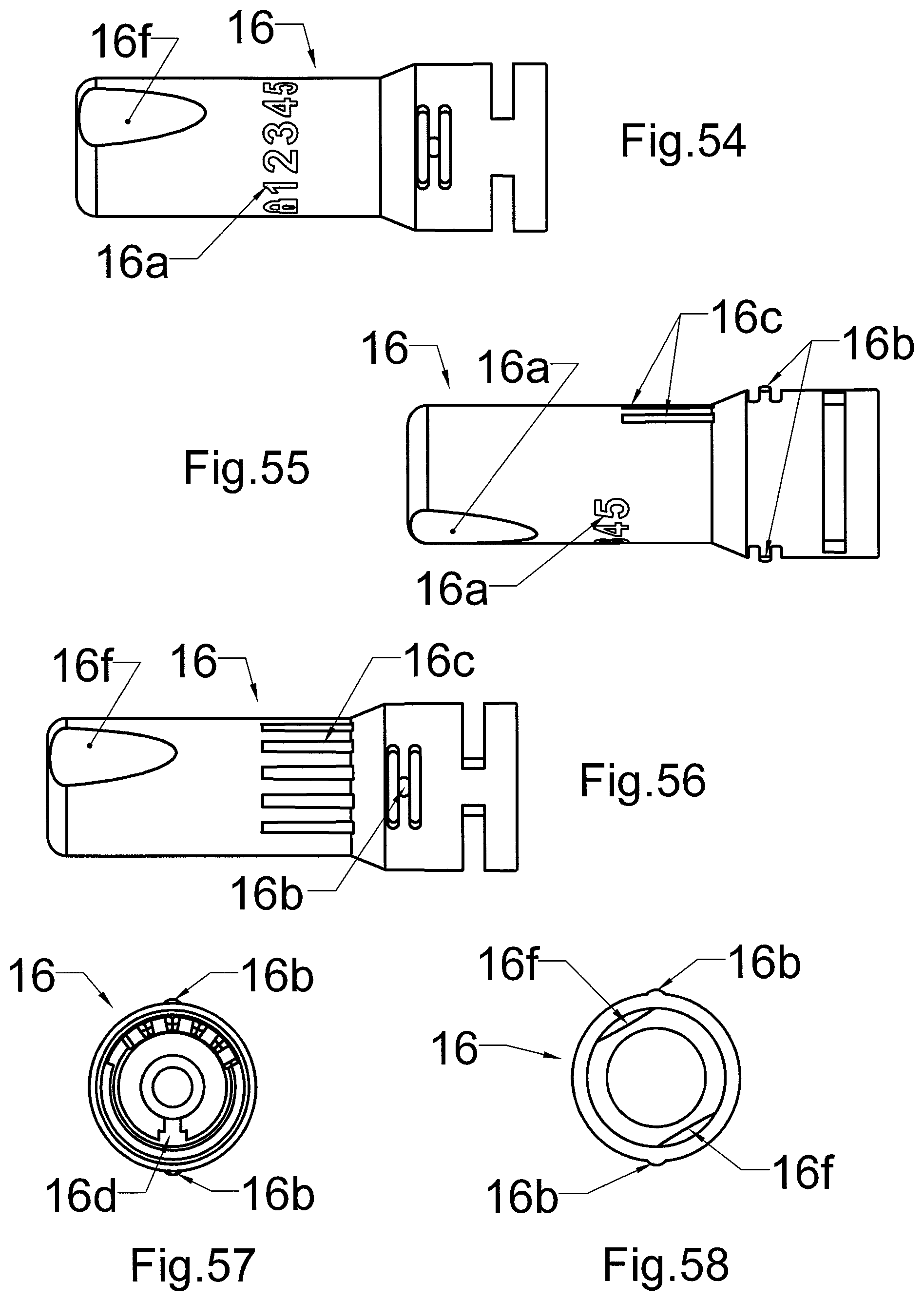
[0045] FIG. 54, FIG. 55 and FIG. 56 present the button from the three separate side views,
[0046] FIG. 57 presents the same button from the front and FIG. 58 presents the button from the back.
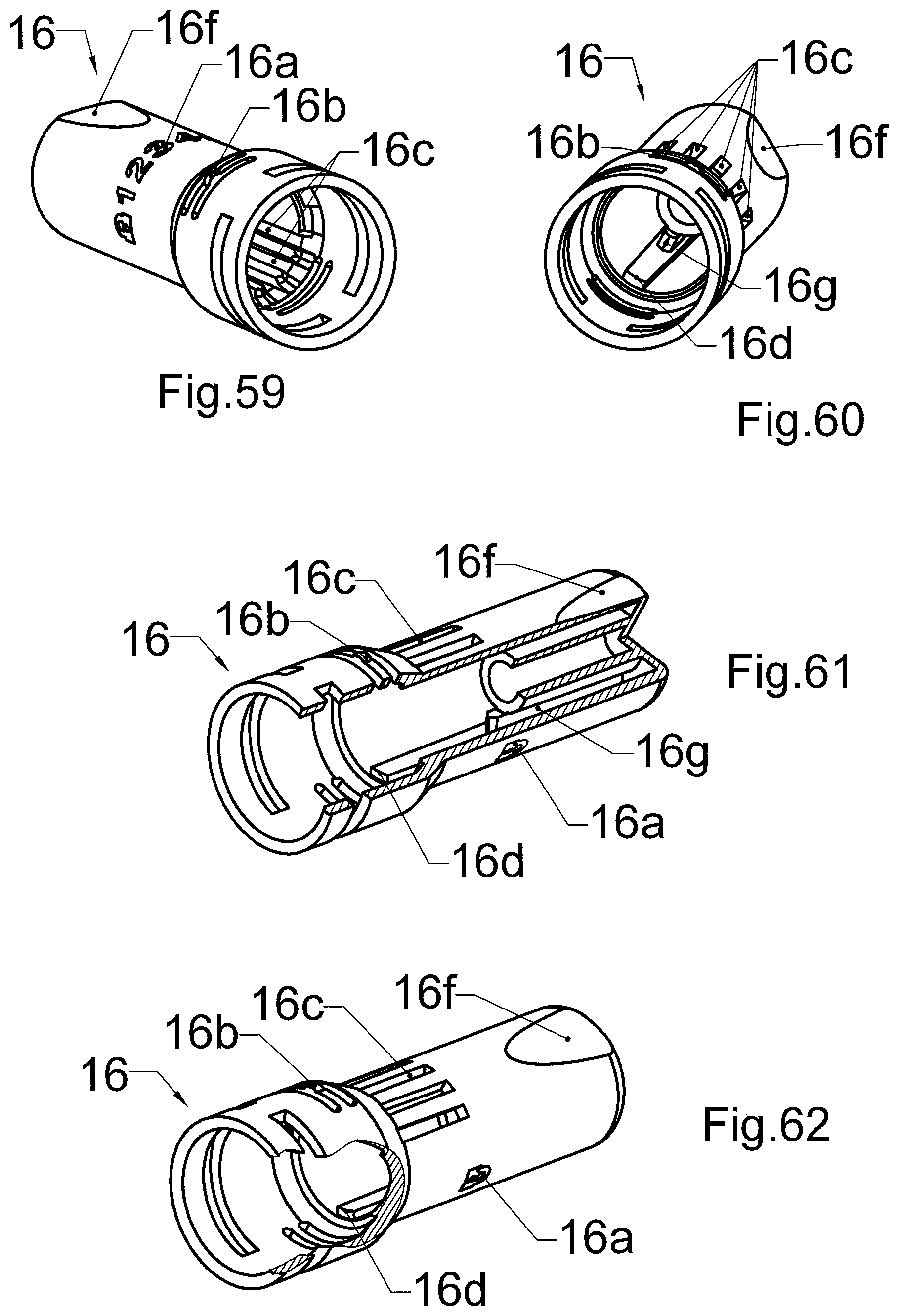
[0047] FIG. 59 and FIG. 60 present two different axonometric views of the button, while FIG. 61 and FIG. 62 present another axonometric view of the button with two different partial cross-sections.
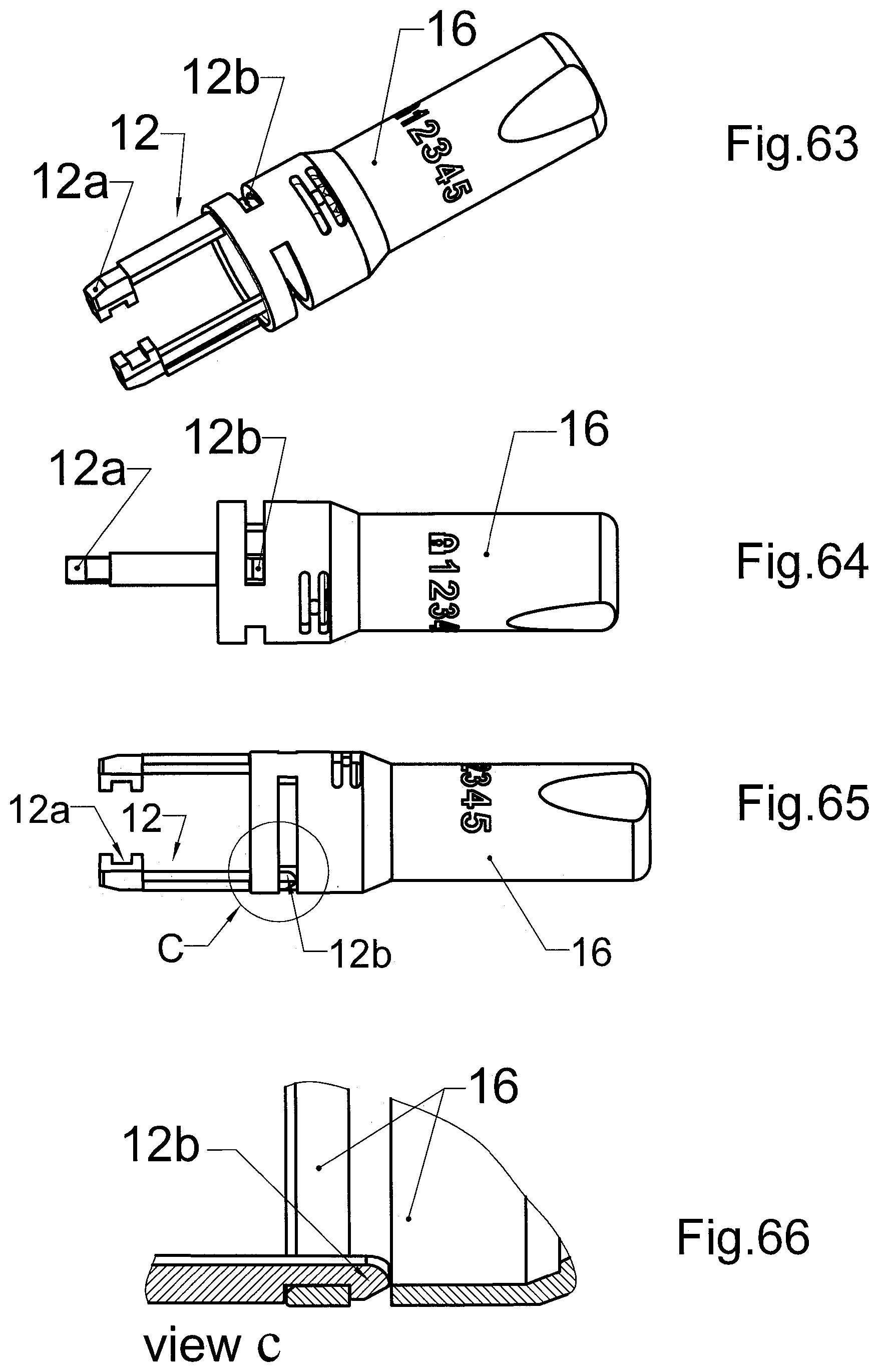
[0048] FIG. 63 presents the button with two mounted side sliders in axonometric view while FIG. 64 and FIG. 65 present the same button with side sliders in two different views from the sides.
[0049] FIG. 66 presents the cross-section of a magnified detail of mounting the side slider to the button from FIG. 65.
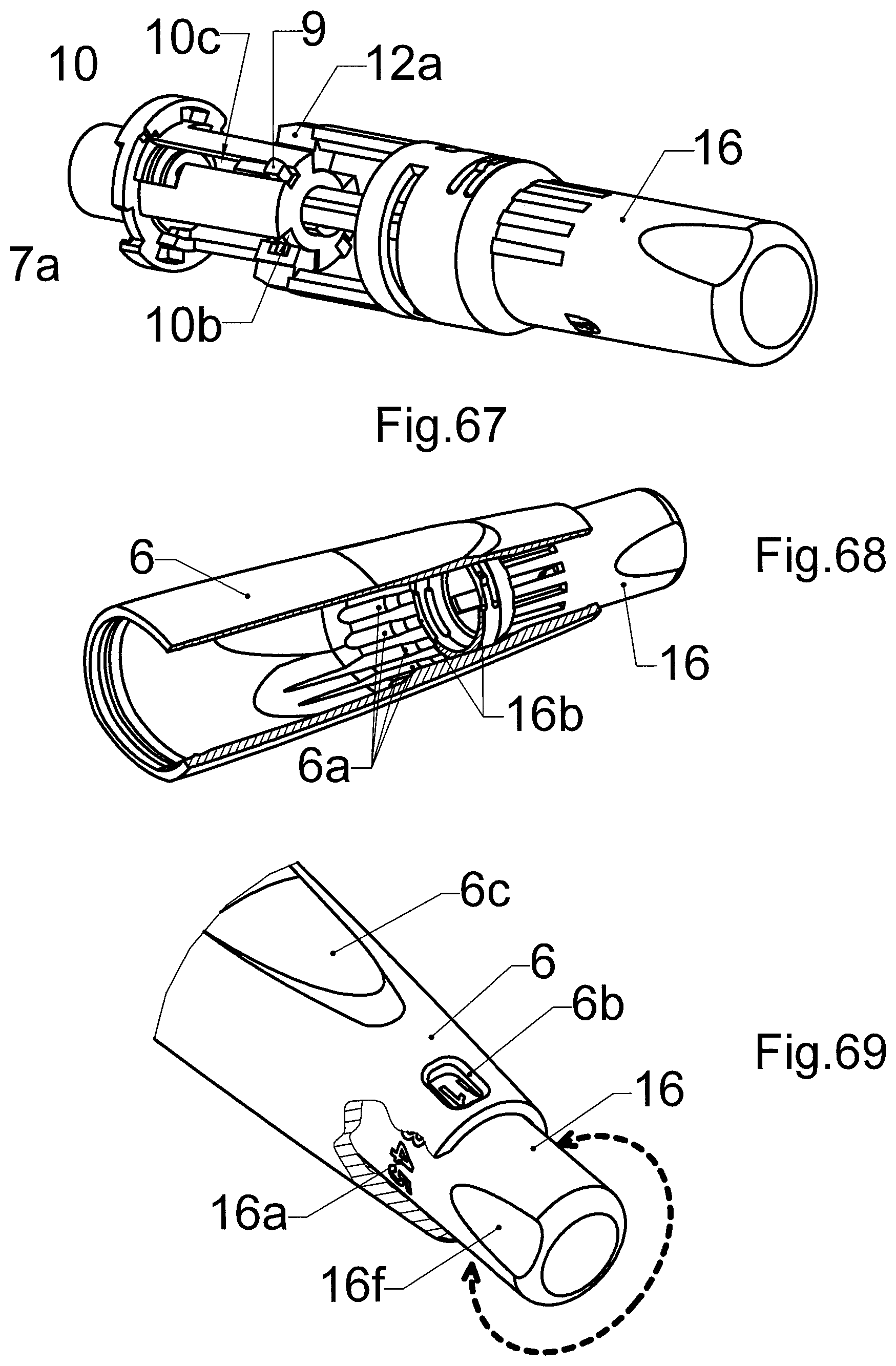
[0050] FIG. 67 presents the mechanism unit in axonometric view, without the casing.
[0051] FIG. 68 and FIG. 69 present in two axonometric views partial cross-sections of the main body with assembled button.
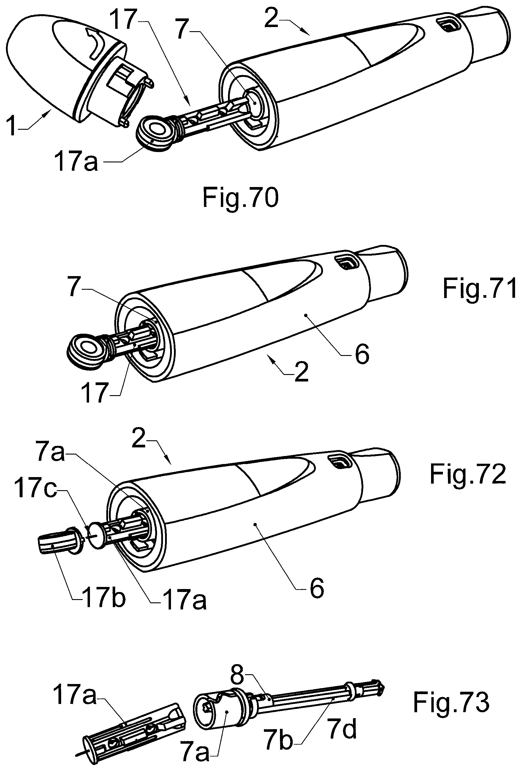
[0052] FIG. 70, FIG. 71 and FIG. 72 present three subsequent phases of installing the lancet in the puncturing device while FIG. 73 presents the same lancet socket with used lancet, removed by the ejector.
[0053] Figures from FIG. 74 to FIG. 97 present six described below, subsequent phases of the functioning of the device during performing the puncture.
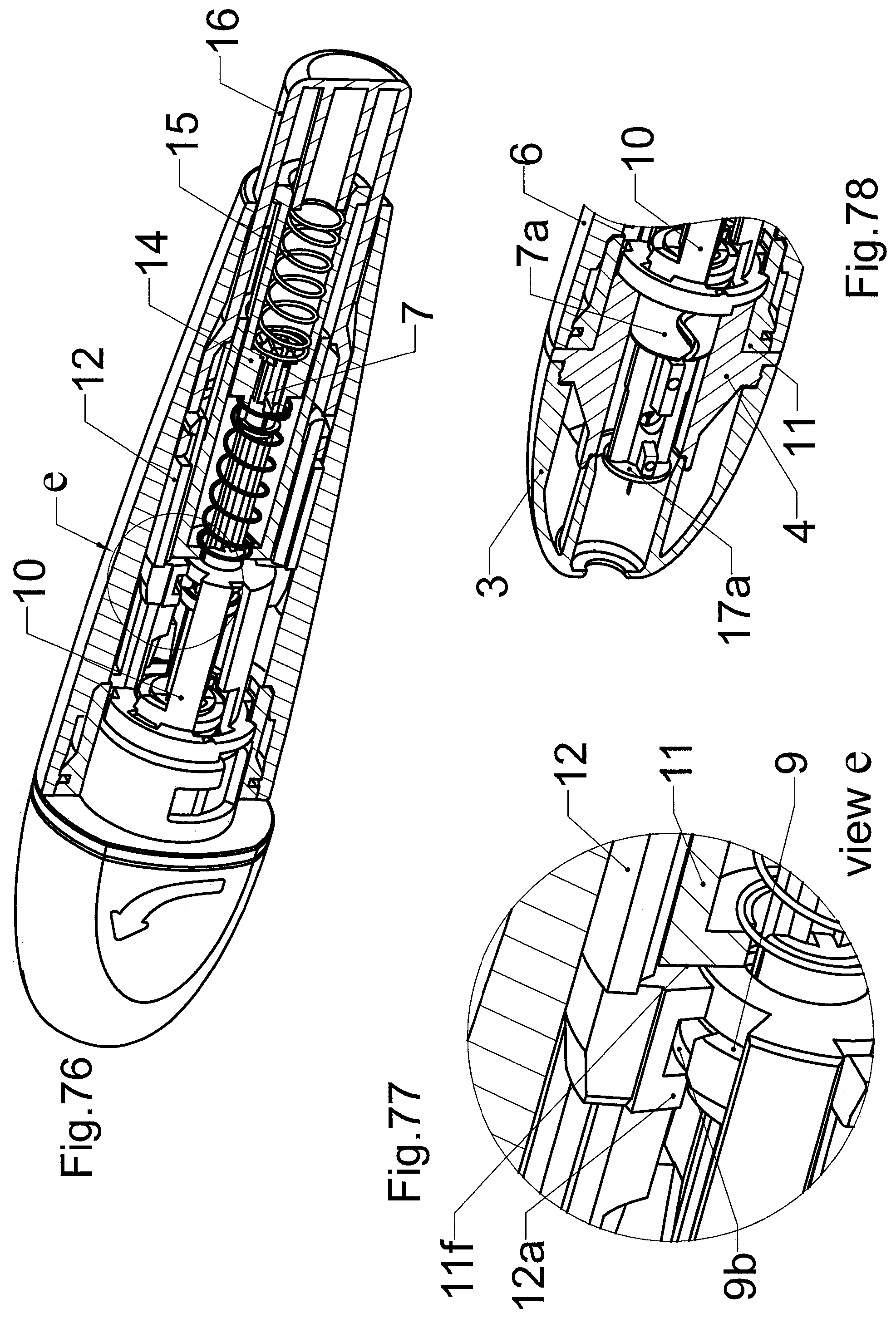
[0054] FIG. 74, FIG. 75, FIG. 76, FIG. 77 and FIG. 78 present the cross-sections of the device during the first phase.
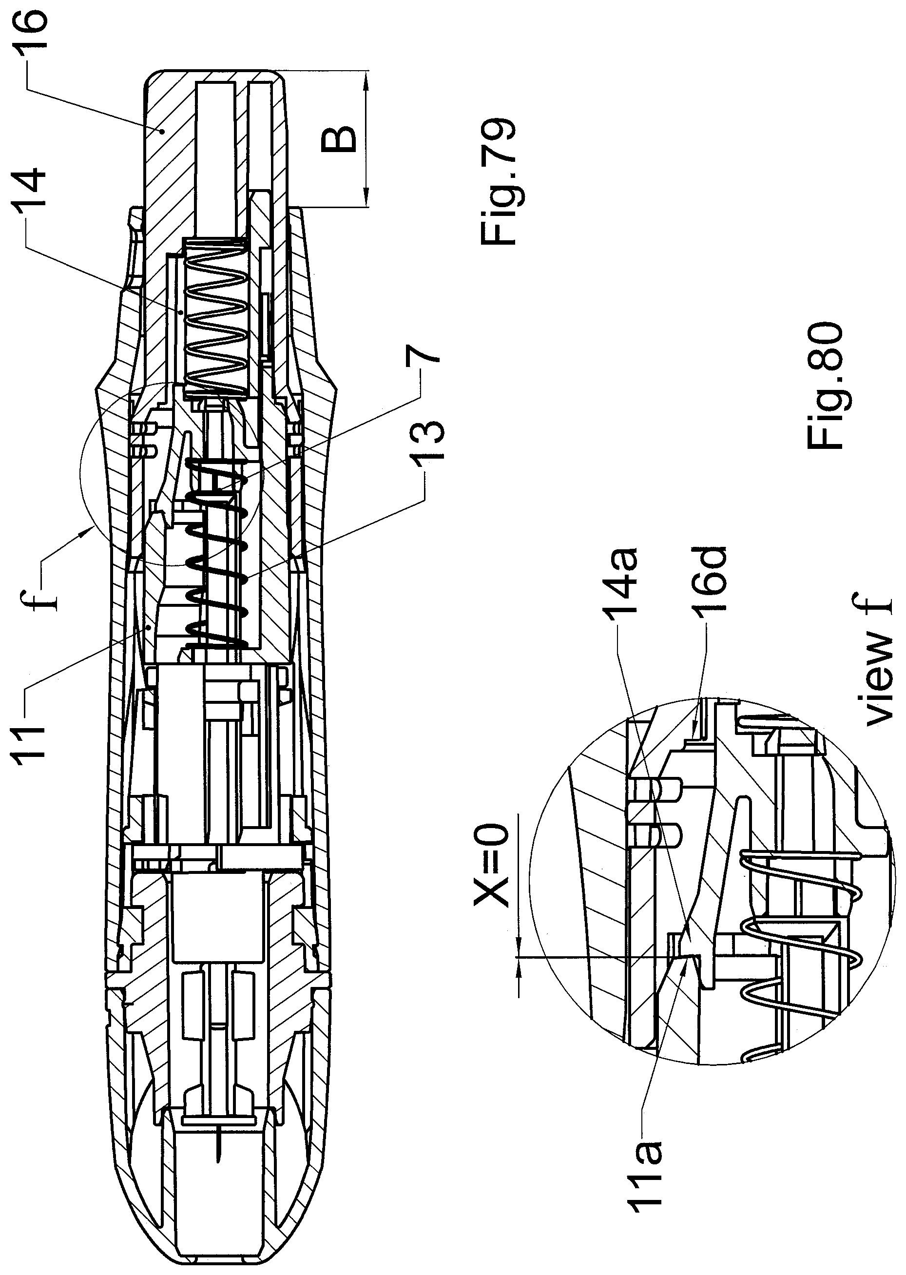
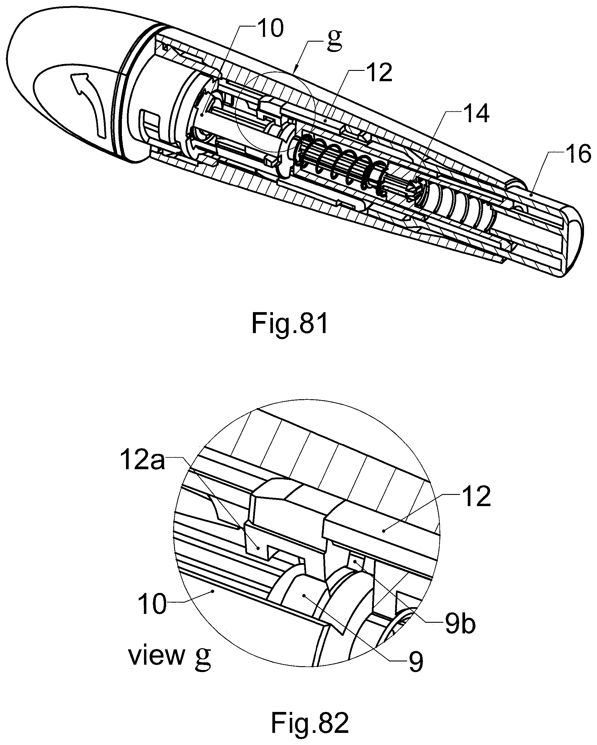
[0055] FIG. 79, FIG. 80, FIG. 81 and FIG. 82 present the cross-sections of the device during the second phase.
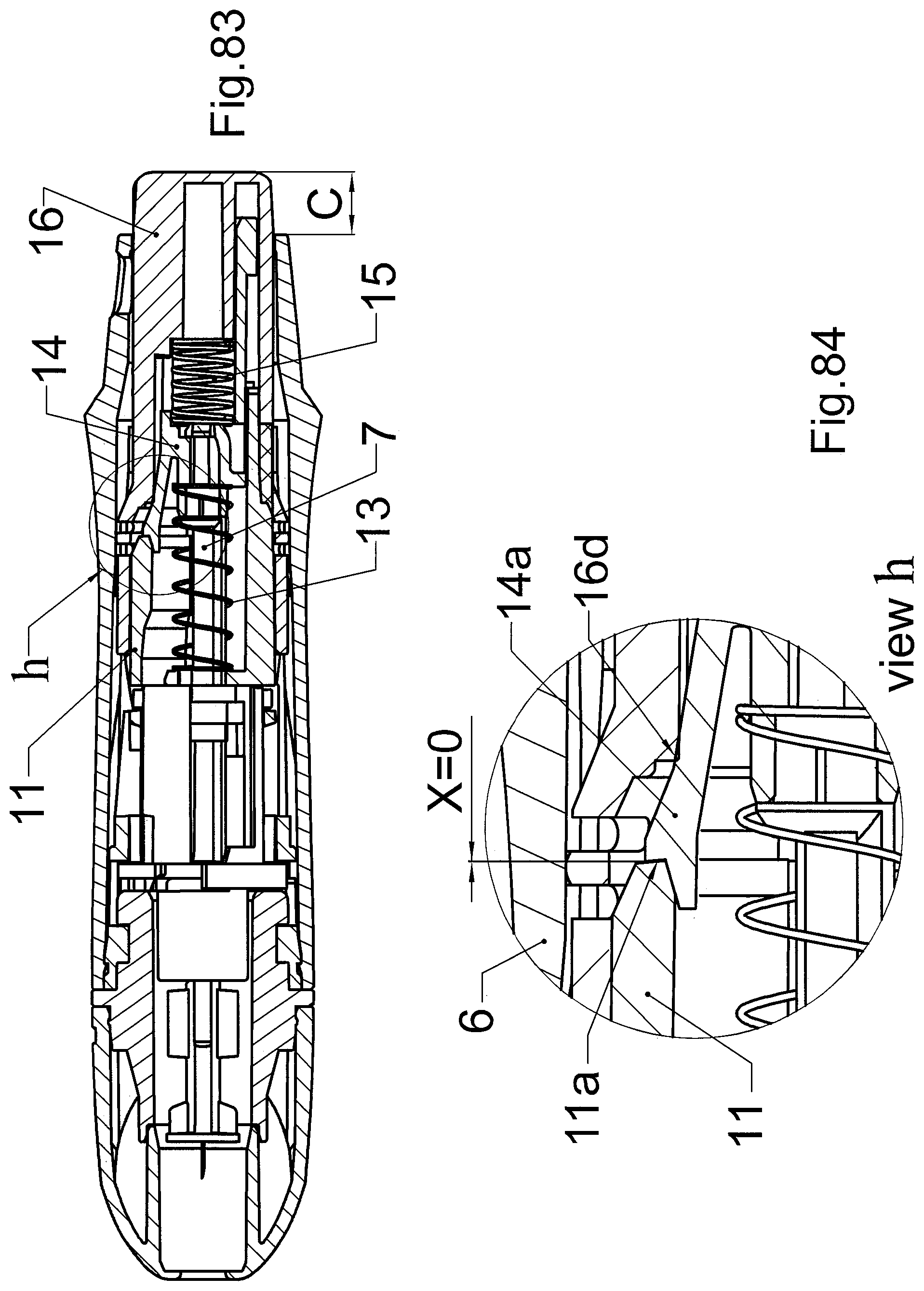
[0056] FIG. 83, FIG. 84, FIG. 85 and FIG. 86 present the cross-sections of the device during the third phase.
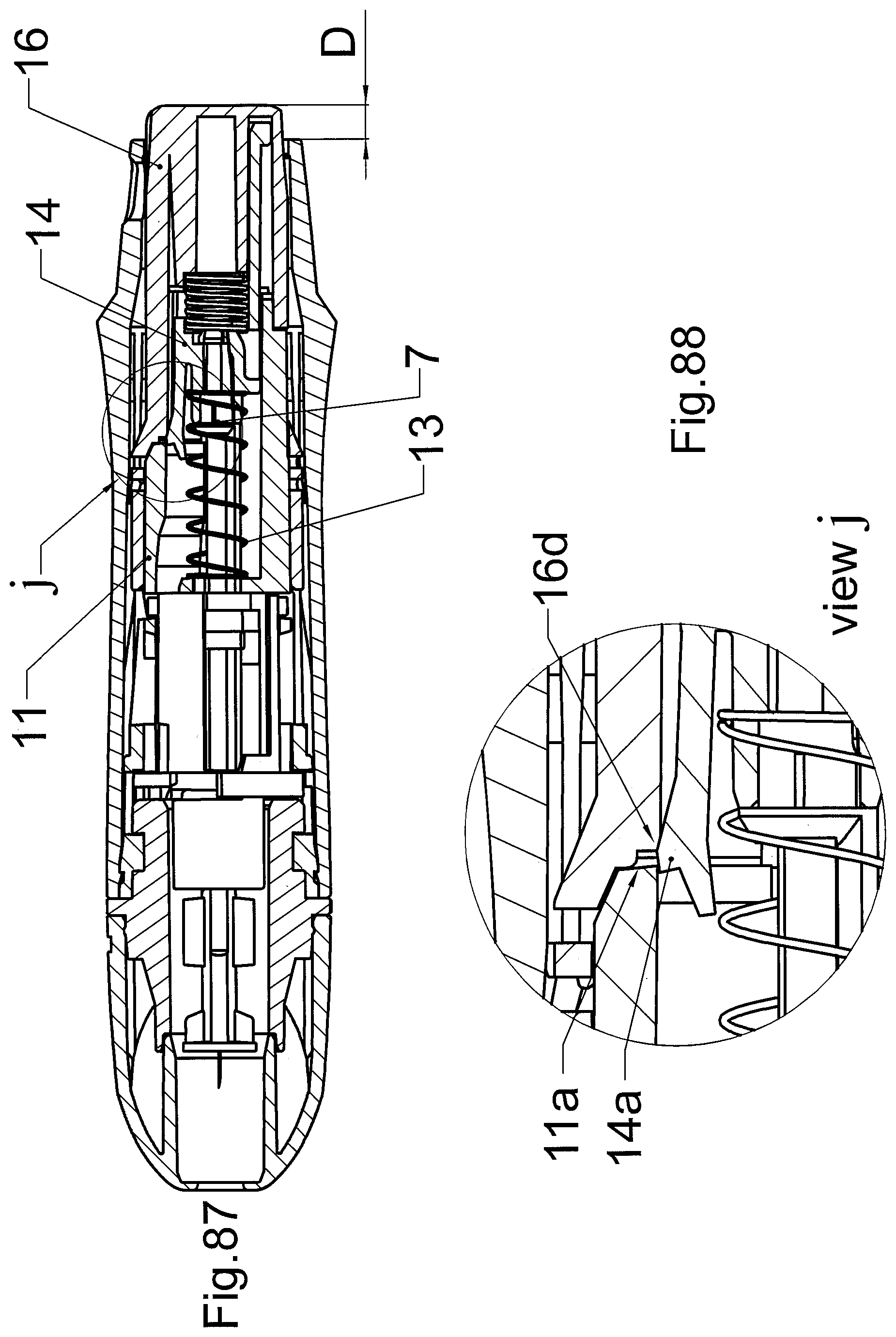
[0057] FIG. 87, FIG. 88, FIG. 89 and FIG. 90 present the cross-sections of the device during the fourth phase.
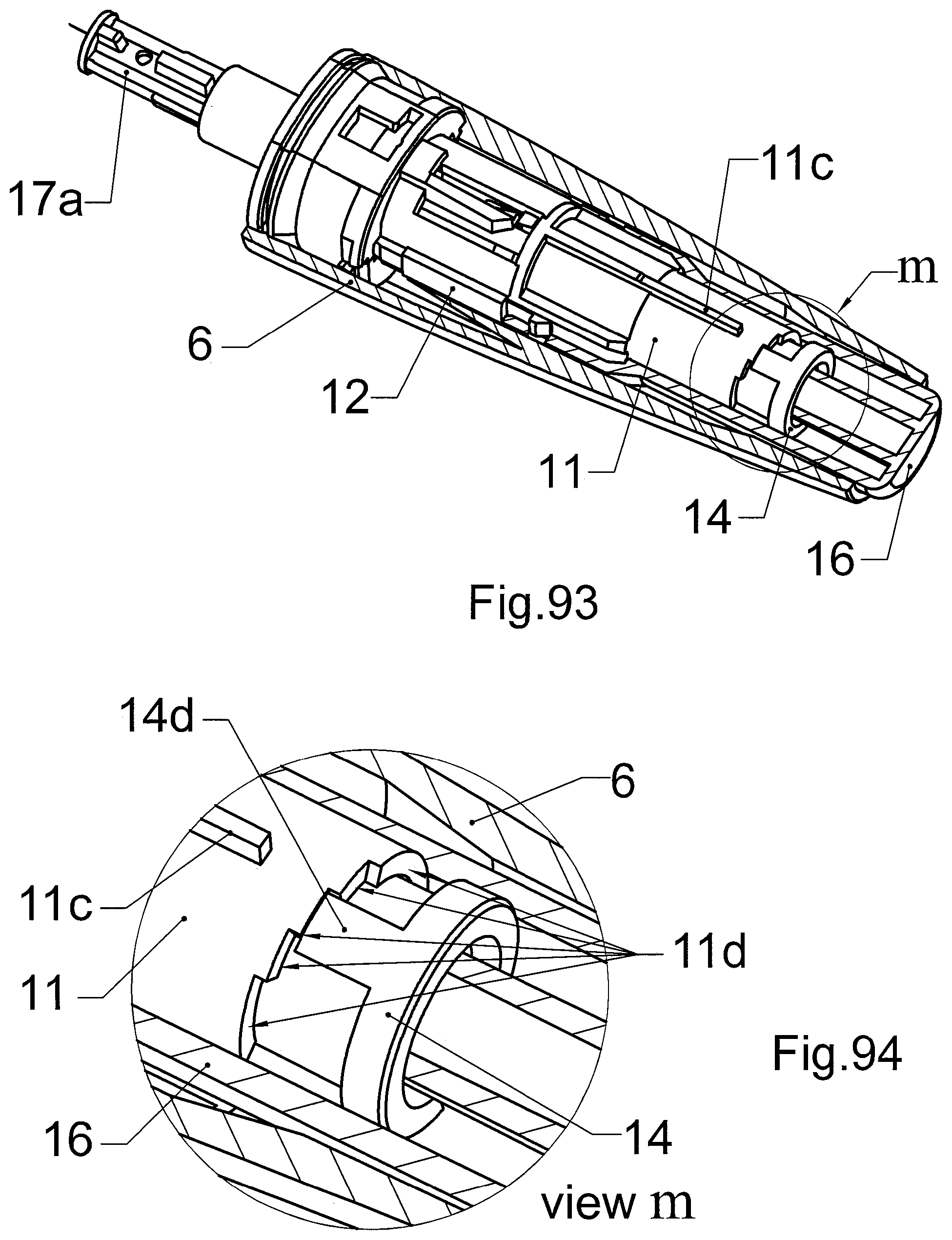
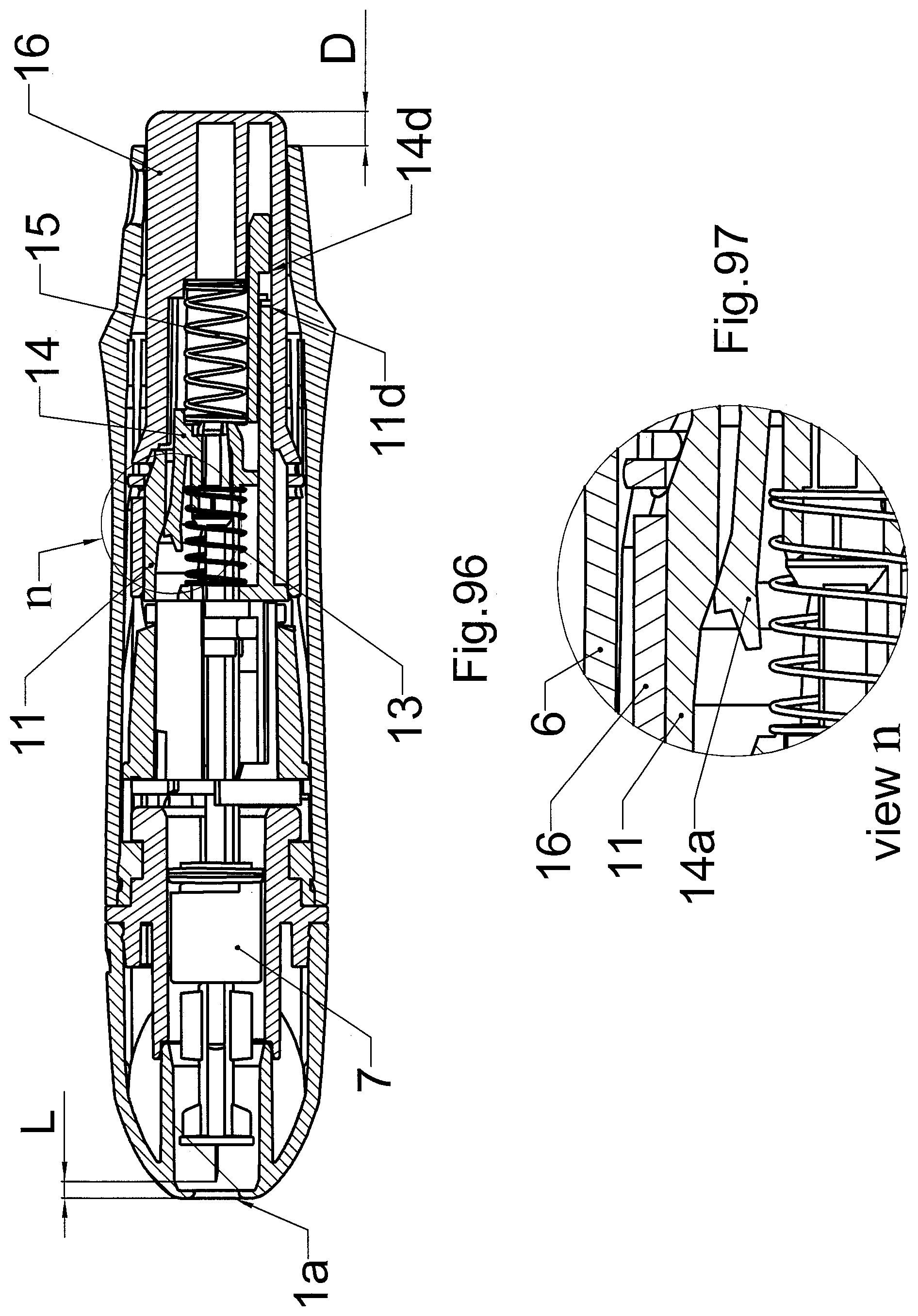
[0058] FIG. 91, FIG. 92, FIG. 93 and FIG. 94 present the cross-sections of the device during the fifth phase and FIG. 96 and FIG. 97 present the cross-sections of the device during the sixth phase of its activity.
[0059] Below you will find a detailed description of the exemplary embodiment of the invention. The puncturing device is composed of the main body 2 and the cup 1, mounted separatable on the main body 2. The end of the device with the cup 1 is its front part; therefore, the opposite end is the back end of the device. The top of the device is where the window in the body for the symbols for the puncture depth is located, described in the further part. The cup 1 is composed of the outer sheath 3 and the permanently attached inside it cup base 4. The main body 2 is composed of the mechanism unit 5, located in the casing 6. The mechanism unit 5 consists of mechanism body 11, fixed in place by its shape in casing 6. In the mechanism body 11 there is the lancet socket 7, ejector 8, driver 9, driver setting 10, return spring 13 and driving sleeve 14. The driving sleeve 14 is covered by button 16, inked with two side sliders 12, which slide in the side channel 11e of the mechanism body 11. The front latches 12a of the sliders 12 reach inside the body 11 and cooperate with the driver 9. Between the driving sleeve 14 and button 16 there is the drive spring 15. Lancet socket 7 has chamber 7a for lancet 17 and oblong guide 7b. The chamber 7a is run in channel 4d of the base 4 of the cup 1. On the free end of the guide 7b the driving sleeve 14 is fixed on with latches (7d). The ejector 8 is fitted sliding on the guide 7b. The setting of driver 10 is fitted rotating inside the mechanism body 11. The driver 9 is fitted sliding inside the driver setting 10. The said guide 7b of the lancet socket 7 protrudes through the driver 9, driver setting 10, through transverse partition 11f of the mechanism body 11 and return spring 13. Cup 1 is assembled to the main body with bayonet connector, which consists of notches 4b in the cup base 4 and corresponding projections 11b in the front part of the mechanism body 11. After removing the cup 1, a disposable lancet 17 is installed by pushing it into the chamber 7a of the lancet socket 7, deep inside the chamber, until noticeable resistance is felt. In such state the puncturing device is blocked, so is impossible for the lancet socket 7 to neither retract inside of the casing 6 nor puncture with the lancet 17 assembled in the socket. After installing the lancet 17 in the lancet socket 7 the blade cover 17b is twisted off and removed, thus uncovering the metal puncturing blade 17c, so in other words the lancet 17 safety is removed. In the described embodiment the widely known and commonly used lancet 17 is applied, in which the metallic needle is embedded in plastic fitting with cover 17b of the sharp end of the needle, divided from the main part of the fitting with a necking. In order to remove the cover 17b it must be twisted off around the lancet axis, which leads to breaking of the plastic in said necking and then removing it from the blade 17c it covered. In order to install the mechanism unit from the front into the body 11, the driver setting 10 is inserted and then the driver 9 is slid inside it. Then the ejector 8 is mounted on the guide 7b of the lancet socket 7 and then the guide 7b of the lancet socket 7 with the ejector 8 is put through in the central opening of the driver 9. The return spring 13 is placed on the end of the guide 7b protruding from the end part of the body 11, then rested on the traverse partition 11f of the body 11 and then the driving sleeve 14 is inserted into the body 11 from the back. By overcoming the resistance of the return spring 13 and the latches 7d of the guide 7b, the driving sleeve 14 is locked on the back part of the guide 7b of the lancet socket 7. Then the side sliders 12 are inserted in the side channels 11e of the mechanism body 11 and moved towards the back of the mechanism body 11 to its maximum position. The drive spring 15 is inserted into the driving sleeve 14 and then the driving sleeve 14 with the drive spring 15 is covered by the notched button 16. The front part of the button 16 catches on the back latches 12b of the side sliders 12. Such assembled mechanism unit 5 is inserted from the front into the casing 6 until a circumferential projection of the casing 6 clicks in a circumferential groove on the front end of the mechanism body 11. When assembled, part of the button 16 with finger notches 16f, which make it easier to rotate the button 16 against the casing 6, protrudes from the main body 2. Fitting the cup 1 to the main body 2 is done by inserting the cup 1 deep inside the main body 2, taking care to aim the two notches 4b of the cup 1 onto the two projections 11b inside the mechanism body 11. After pushing the cup 1 into the front surface of the main body 2, the cup 1 is twisted clockwise until recognizable click and definite resistance. In order to facilitate twisting the cup 1 against the main body 2, the sheath 3 of the cup 1 has two notches 3b, which make gripping the cup 1 with fingers easier, while the casing 6 has elevated shape 6c, easy to grip. Unintended twisting of the sheath 3 against cup base 4 is prevented by the interlock of the components that is the projections 3a inside the cup sheath 3, which go into the notches 4c in the base 4.
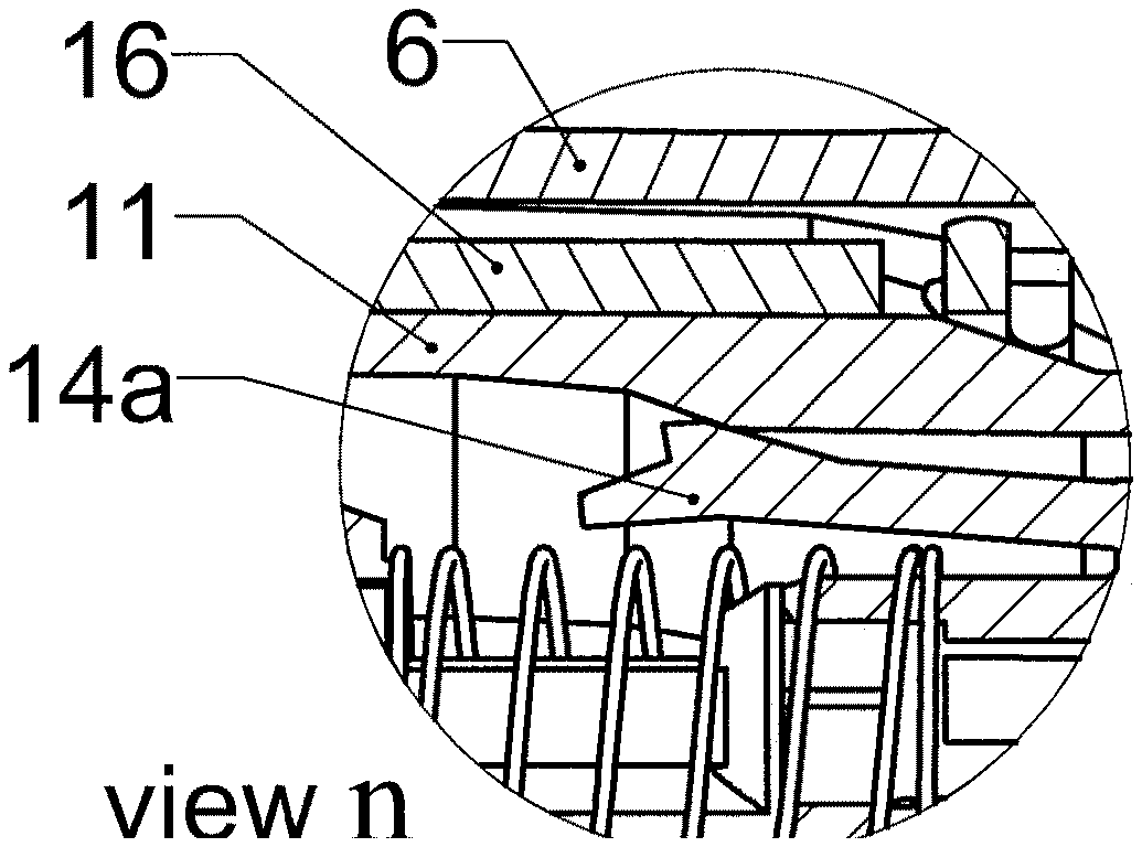
[0060] The puncturing device has puncture depth step regulation function--i.e., possibility to change the distance the lancet blade 17c, is shot out of the front surface 3c of the cup sheath 3. Choosing the depth is done by rotating button 16 in angles ranging from Oto 120.degree., in which the button 16 locks clearly and audibly with a click in one of the six positions. The first of these positions, in the described exemplary embodiment is indicated on the button 16 with a padlock symbol. This position is so-called locked position, in which pressing the button 16 is not possible and this position secures the device from unintended activation. The set depth is indicated by the symbols 16a on the button 16, visible through a window 6b in the casing 6 (FIG. 69). In the described exemplary embodiment these symbols are numbers from 1 to 5. The stepped rotation of the button 16 is the result of two projections 16b, located on the opposite sides of the button 16 and being its integral parts, locking in twelve relevant locking channels 6a on the inner surface of the casing 6 (FIG. 68).
[0061] The FIG. 74 presents the cross-section of the puncturing device in the first phase that is the preparation for puncturing. In this phase, the button 16 protrudes maximally towards the back of the device by distance A, which in this exemplary embodiment amounts to ca. 14 mm. This protrusion is limited by two side sliders 12. In this phase the front latches 12a of the side sliders 12 rest on the front surface of the transversal partition 11f of the body 11 (FIG. 77). The button 16 protrudes maximally towards the back because of the drive spring 15 and the return spring 13. The return spring 13 is loaded initially and based on the transverse partition 11f of the mechanism body 11 with one end and the second end exerting pressure on the driving sleeve 14, causing it to be pushed out of the mechanism body 11 that is towards the back. The retracting driving sleeve 14 exerts pressure on the drive spring 15, which in turn exerts pressure on the inner surface of the button 16, pushing it out of the mechanism body 11. The driving sleeve 14 has a front latch 14a, which is situated at a distance X, amounting to ca. 0.5 mm behind the stop surface 11a of the mechanism body 11. The driver 9 is positioned at an angle in such a way that its movement along the axis of the device is impossible, because two projections 9a of the driver 9 are positioned directly ahead of the two latches 11g of the mechanism body 11, while the front latches 12a of the side sliders 12 are positioned inside the notches 9b in the driver 9 (FIG. 76 and FIG. 77), thus the sliders 12 are not coupled with the driver 9. Lancet 17a is placed in the lancet socket 7, which is in the back part of the cup 1 (FIG. 74 and FIG. 78). On the outer surface of the body 11, underneath there is a fin 11c, which can engage one of the anti-rotating channels 16c, which are situated on the inner surface of the button 16. The number of these channels corresponds with the number of angular positions, in which the button 16 can be set in order to choose the depth of the puncture. When the button 16 is in the locked position, the fin 11c is on the opposite uniform surface inside button 16 that is out of the anti-rotation channels 16c system, which blocks the button 16 from being pressed and therefore also prevents puncturing or pushing the lancet out. The button 16 is rotary coupled with the driving sleeve 14, because its inner axial projection 16g fits in the axial notch 14d in the sleeve 14. Therefore rotating the button 16 automatically rotates the sleeve 14.
[0062] In phase two (Figures from 79 to 82) the symbol 16a is visible in the window 6b of the casing 6, which indicates the chosen depth of the puncture set with the button 16 and the fin 11c is positioned next to one of the channels 16c of the button 16. In this phase the pressed button 16 protrudes from the casing 6 at the distance B (FIG. 79), smaller than distance A and in this exemplary embodiment amounting to ca. 12 mm. As a result, the drive spring 15 becomes slightly compressed. The pressure of the drive spring 15 exerted on the driving sleeve 14 makes the driving sleeve 14 move, together with the lancet socket 7 along the axis of the device, deeper into the mechanism body 11, until the latch 14a of the driving sleeve 14 rests on the stop surface 11a of the mechanism body 11 (FIG. 80), resulting in reduction of the distance X to zero. Moving the driving sleeve 14 also causes slight compression of the return spring 13. The side sliders 12, coupled with the button 16, move forward, partially protruding from the notches 9b of the driver 9 (FIG. 81 and FIG. 82), but the driver 9 stays in the same position as in phase one.
[0063] In third phase (Figures from 83 to 86) the button 16 is pushed even deeper, therefore it protrudes from the casing 6 by distance C (FIG. 83), which in this exemplary embodiment amounts to ca. 5.5 mm. Pushing the button deeper causes increasing the tension of the drive spring 15. The latch 14a of the driving sleeve 14 is still rested on the stop surface 11a of the mechanism body 11 (X=0, FIG. 84) and the tension of the return spring 13 does not change. The result of the movement of the button 16 is that the activating surface 16d touches the latch 14a of the driving sleeve 14 (FIG. 84). The side sliders 12, connected with the button 16, move towards the front of the device, coming out of the notches 9b of the driver 9 completely (FIG. 85 and FIG. 86). The driver 9 and driver setting 10 remain in the same position as in the first two phases.
[0064] In the fourth phase (Figures from 87 to 90) the button 16 is pressed till the end and rests on the body 11, but it protrudes from the casing 6 only by distance D (FIG. 87), which amounts in the exemplary embodiment to ca. 3 mm. The drive spring 15 is squeezed maximally and the activating surface 16d, pushing the latch 14a causes it to bend, to the position below the edge of the stop surface 11a (FIG. 88) and thus activating of the device.
[0065] In the fifth phase (Figures from 91 to 94) the drive spring 15 is released, rapidly pushing out the driving sleeve 14 with lancet socket 7 and the lancet 17, installed in the socket 7. The ejector 8, which is sliding fitted in the guide 7b of the lancet socket 7, remains in the same position, held by the driver 9, the position of which also remains the same. The movement of the driving sleeve 14 also causes compression of the return spring 13 and ends in the moment when the bumper 14c of the driving sleeve 14 hits one of the limiting steps 11d in the back part of the mechanism body 11. These steps define the depth of the puncture in the skin with the lancet 17 that is the distance K, in which the tip of the lancet blade 17c slides out of the front part 1a of the cup 1. The bumper 14c of the driving sleeve 14 hits the limiting step 11d, directly where the bumper 14c is, as a result of the rotating motion of the driving sleeve 14, caused by rotating the button 16 when selecting the depth of the puncture (FIG. 93 and FIG. 94). In the described exemplary embodiment the differences between the heights of the adjacent limiting steps 11d equal 0.5 mm, which in result allows the user to regulate the depth of the puncture, ranging from 0.5 mm to 2.5 mm, with steps of 0.5 mm. By changing the number of the steps 11d and their pitch it is easy to adjust the range of the puncture depths, depending on the needs of various user groups. The change of the step 11d height it is possible also to compensate for the difference in lengths of various types of lancets from different manufacturers.
[0066] In the sixth phase (FIG. 96 and FIG. 97) the button 16 remains pushed in all the way, however the driving sleeve 14 with the lancet socket 7 and the lancet 17 is retracted by the return spring 13 until the moment when the tension in the return spring 13 and the drive spring 15 equalize each other. In this phase the tip of the blade 17c retracts and is covered inside the cup 1. Releasing the button 16 causes the button 16, the return spring 13, the drive spring 15 and the driving sleeve 14 with the lancet socket 7 and the lancet 17 to return to their initial positions, described above as first phase.
[0067] In order to remove the used lancet 17 the cup 1 is removed from the main body 2 by rotating it counter-clockwise and then removing it from the casing 6. Because the base 4 of the cup 1 is coupled with the driver setting 10 with two fins 4a of the cup base 4 that enter the two windows 10a of the driver setting 10. The described above rotation of the cup 1 to remove it from the main body also results in the rotation of the driver setting 10, at this point coupled with the fins 4a. The rotation of the driver setting 10 also changes the angular position of the driver 9, because it is coupled with the driver setting 10 with the drive projections 9a. Rotating the driver 9 causes it to couple with the front latches 12a of the side sliders 12. In this system the driver projections 9a can move along the guide channels 11h of the mechanism body 11, but the length of these channels is smaller than the movement range of the button 16. Pressing the button 16, and therefore also moving the side sliders 12 along with the driver 9 linked with them at the ends, is possible only until the driver projections 9a hit the front walls of the channels 11h. Thus limiting the degree to which the button 16 can be pressed, prevents activation of the puncturing device, because the activating surface 16d of the pushed button 16 is not able to release the latch 14a of the driving sleeve 14, rested on the stop surface 11a of the body 11. However, the movement range of the driver 9 is enough to move the ejector 8 on the guide 7b so far ahead that the ejector 8 goes through the window 7c in the chamber 7a and pushes the lancet 17 out of this chamber. Releasing button 16 activates the return spring 13 and the drive spring 15, what makes the ejector 8, driver 9, side sliders 12 and driving sleeve 14 with empty lancet socket 7 returns to their initial position that is to first phase described above. The reinstallation of the cup 1 in the main body 2 results in fins 4a of the cup base 4 enter first in the windows 10a of the driver setting 10 and then rotate it along with the driver 9. In the new position of the driver 9 its projections 9a are in position beyond the front latches 12a of the side sliders 12, therefore it is possible to fully press the button 16 and, if a new lancet 17 is placed in the lancet socket 7, it is possible to perform another puncture.
LIST OF DESIGNATIONS
[0068] 1 cup [0069] 2 main body [0070] 3 cup sheath [0071] 3a projections inside the cup sheath 3b notch for fingers [0072] 4 cup base [0073] 4a fin [0074] 4b notch for bayonet connector with the body 11 [0075] 4c notch for the inner projection 3a of the cup sheath [0076] 4d notch for lancet chamber 7a [0077] 5 mechanism unit [0078] 6 casing [0079] 6a latch channel [0080] 6b window [0081] 6c elevated shape [0082] 7 lancet socket [0083] 7a lancet chamber [0084] 7b guide [0085] 7c throughfeed window [0086] 7d latch of lancet socket [0087] 8 ejector [0088] 9 driver [0089] 9a driver projections 9b notches [0090] 9c notch for ejector 8 [0091] 10 driver setting [0092] 10a window for the fin 4a [0093] 10b notch for the slider [0094] 10c notch for the driver [0095] 11 mechanism body [0096] 11a stop surface of the body [0097] 11b bayonet connector projection locking with the base 4 [0098] 11c fin of the body [0099] 11d step limiting puncture depth [0100] 11e channels for side sliders [0101] 11f transversal partition [0102] 11g latch of the body [0103] 11h channel leading the driver 9 projection [0104] 12 side slider [0105] 12a front latch of the side slider [0106] 12b back latch of the side slider [0107] 13 return spring [0108] 14 driving sleeve [0109] 14a latch of the driving sleeve [0110] 14c bumper of the driving sleeve [0111] 14d axial notch for the projection 16g [0112] 15 drive spring [0113] 16 button [0114] 16a symbol indicating puncture depth [0115] 16b springy projection [0116] 16c anti-rotary channel [0117] 16d activating surface [0118] 16f notch for finger [0119] 16g projection coupling the button with the notch 14d [0120] 17 complete lancet [0121] 17a armed lancet [0122] 17b lancet blade cover [0123] 17c lancet blade
* * * * *
D00000
D00001
D00002
D00003
D00004
D00005
D00006
D00007
D00008
D00009
D00010
D00011
D00012

D00013
D00014
D00015
D00016
D00017
D00018

D00019
D00020
D00021
D00022
D00023

D00024
D00025

D00026

D00027
D00028
XML
uspto.report is an independent third-party trademark research tool that is not affiliated, endorsed, or sponsored by the United States Patent and Trademark Office (USPTO) or any other governmental organization. The information provided by uspto.report is based on publicly available data at the time of writing and is intended for informational purposes only.
While we strive to provide accurate and up-to-date information, we do not guarantee the accuracy, completeness, reliability, or suitability of the information displayed on this site. The use of this site is at your own risk. Any reliance you place on such information is therefore strictly at your own risk.
All official trademark data, including owner information, should be verified by visiting the official USPTO website at www.uspto.gov. This site is not intended to replace professional legal advice and should not be used as a substitute for consulting with a legal professional who is knowledgeable about trademark law.