Double Action Nose Mount Quattro Stanchion
Paradis; James ; et al.
U.S. patent application number 17/004519 was filed with the patent office on 2021-03-11 for double action nose mount quattro stanchion. The applicant listed for this patent is Hussey Seating Company. Invention is credited to John Fisher, James Paradis, Paul-Jacob Michael Richmond.
| Application Number | 20210068546 17/004519 |
| Document ID | / |
| Family ID | 1000005074927 |
| Filed Date | 2021-03-11 |


View All Diagrams
| United States Patent Application | 20210068546 |
| Kind Code | A1 |
| Paradis; James ; et al. | March 11, 2021 |
DOUBLE ACTION NOSE MOUNT QUATTRO STANCHION
Abstract
A double action seating unit to be mounted to a nose of a platform is described. The double action seating unit includes a seat assembly, a back assembly and at least two stanchion. Each stanchion has a front bracket, a rear bracket, a stanchion tube and two pivot straps. The front bracket attaches the seat portion to the stanchion, the rear bracket attaches the stanchion to the nose of the platform and the stanchion tube attaches the back assembly to the stanchion. Each pivot strap connects an associated stanchion tube, the rear bracket and the front bracket. The double action seating unit can move between a use configuration and a storage configuration. The two pivot straps cause the seat assembly and the back assembly to simultaneously rotate when the double action seating unit moves between the use configuration and the storage configuration.
| Inventors: | Paradis; James; (West Newfield, ME) ; Fisher; John; (Yarmouth, ME) ; Richmond; Paul-Jacob Michael; (Biddeford, ME) | ||||||||||
| Applicant: |
|
||||||||||
|---|---|---|---|---|---|---|---|---|---|---|---|
| Family ID: | 1000005074927 | ||||||||||
| Appl. No.: | 17/004519 | ||||||||||
| Filed: | August 27, 2020 |
Related U.S. Patent Documents
| Application Number | Filing Date | Patent Number | ||
|---|---|---|---|---|
| 62896667 | Sep 6, 2019 | |||
| Current U.S. Class: | 1/1 |
| Current CPC Class: | A63J 25/00 20130101; A47C 1/121 20130101 |
| International Class: | A47C 1/121 20060101 A47C001/121; A63J 25/00 20060101 A63J025/00 |
Claims
1. A double action seating unit to be mounted to a nose of a platform, the double action seating unit comprising: a seat assembly; a back assembly; and at least two stanchions, each stanchion including a front bracket, a rear bracket, a stanchion tube and two pivot straps, wherein the front bracket is configured to attach the seat assembly to the stanchion, wherein the rear bracket is configured to attach the stanchion to the nose of the platform, wherein the stanchion tube is configured to attach the back assembly to the stanchion, wherein each pivot strap is configured to connect an associated stanchion tube, the rear bracket and the front bracket, wherein the double action seating unit is configured to move between a use configuration and a storage configuration, and wherein the two pivot straps are further configured to simultaneously move the seat assembly and the back assembly when the double action seating unit moves between the use configuration and the storage configuration.
2. A seating system comprising a plurality of the double action seating units of claim 1.
3. The seating system of claim 2, wherein the seating system includes a top row and at least one lower row.
4. The seating system of claim 3, wherein the plurality of the double action seating units are disposed on the top row.
5. The seating system of claim 4, wherein the at least one lower row comprises a plurality of single action seating units.
6. The double action seating unit of claim 1, further comprising at least one armrest.
7. The double action seating unit of claim 7, wherein the stanchion tube is further configured to attach the back assembly and the at least one armrest to the stanchion.
8. The double action seating unit of claim 1, wherein the seat assembly is configured to rotate forward when moving from the use configuration to the storage configuration.
9. The double action seating unit of claim 1, wherein the back assembly is configured to rotate backwards when moving from the use configuration to the storage configuration.
10. The double action seating unit of claim 1, wherein the seat assembly is configured to rotate forward and the back assembly is configured to simultaneously rotate backwards when moving from the use configuration to the storage configuration.
11. The double action seating unit of claim 1, wherein the rear bracket includes side plates defining curved slots.
12. The double action seating unit of claim 11, further comprising a pivot location for the stanchion tube, wherein the curved slots arc around the pivot location.
13. The double action seating unit of claim 12, further comprising a pin that goes through a hole in the at least one pivot strap, the curved slots and a hole in the stanchion tube.
Description
STATEMENT REGARDING FEDERALLY SPONSORED RESEARCH OR DEVELOPMENT
[0001] N/A
BACKGROUND OF THE INVENTION
[0002] Various embodiments relate generally to seating systems and devices and, more specifically, relate to folding and telescopic bleachers.
[0003] This section is intended to provide a background or context. The description may include concepts that may be pursued, but have not necessarily been previously conceived or pursued. Unless indicated otherwise, what is described in this section is not deemed prior art to the description and claims and is not admitted to be prior art by inclusion in this section.
[0004] Folding and telescopic seating structures 102 are bleachers that can be retracted closed into a compact vertical stack of tiered seating to save floor space. FIGS. 1A and 1B, collectively referred to as FIG. 1, show a telescopic seating structure 102 with a standard nose mounted chair 103 in the last row in both extended (FIG. 1A) and closed (FIG. 1B) configurations. As shown, each tier of seating, when open or closed, needs to slide past the adjacent tiers and in certain cases, store completely underneath the balcony 101 or other seated platforms.
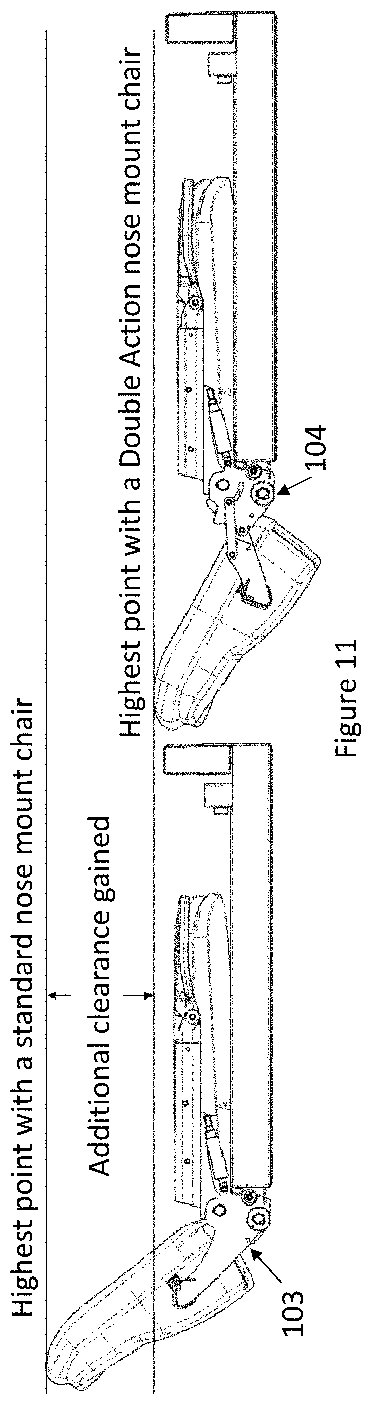
[0005] Certain venues can have a large, comfortable chair 103, which given its magnitude cannot fit within the structures envelope and therefore must be attached to the front beam (hereafter referred to as nose 105) of the tiered seating structure 102. See FIG. 1 as an example of a standard seating section. These larger parts prevent the telescopic structure 102 from storing under a balcony 101 with small clearances to the top of the structure 102. This requires that the entire unit 102 to sit in front of the balcony 101 causing the closed dimension to be large. FIG. 11 shows a side by side comparison showing the clearance gained by using a standard chair 103 (Left) and a double action chair 104 (Right).
[0006] A common application in spectator seating systems is a recessed telescopic seating structure 102 that, when in use, will transition to a secondary level 101 within a venue. For this application it is imperative that the platform 101 can fit fully below the balcony 102 with operational clearance. This clearance then dictates what the overall height of the platform 102 can be and therefore will limit the number of rows that can be used on that platform 102. If a given platform 102 also has a nose mounted chairs 103, then this component will commonly become the highest point on the platform 102. With the chair 103 being the highest point on the unit 102, the limitations of the platform 102 will revolve around them.
[0007] One typical solution would be to have the top row of the telescopic seating structure 102 sit low enough that the highest point on the chairs 103 do not contact the balcony 101. In some cases, this will cause the dimension between the last row of the platform 102 and the tread on the balcony 101 to be large enough that it will require a three-tread transition. This kind of transition requires a larger row space on the top row of the platform 102 to account for the extra step. This approach could have a negative impact on the sightlines for patrons in that row due to the height limitation. Another, common application for these telescopic platforms 102 is to be adjacent to concrete risers. When used in these applications, the telescopic platforms 102 must have the same cross sectional geometry as the concrete to ensure there is no tripping hazards going from the platform 102 to the concrete and that the row of chairs is as consistent as possible. Therefore, increasing the dimension between the last row on the platform to the balcony 101 may not be possible when the platforms are used in this kind of application.
[0008] A second solution that some venues consider is to have the unit 102 hold close to the balcony 101 in the vertical direction. Then they increase the closed envelope of the platform 102 to prevent the nose mounted chairs 103 from hitting the balcony 101. This solution will decrease the amount of useable space left on the floor when the platform 102 is stored and therefore is not a desirable or a practical solution.
[0009] A third solution is to have a larger row space on the last tier of the platform 102 to allow for the use of portable chairs. This solution will provide a tighter fit to the balcony and may allow for another row to be added to the platform. However, it will require installation and removal of all the portable chairs for every event. For many venues, the aesthetics of having a different chair at this location is not an option.
[0010] Some venues may have the capability to work around these limitations, however, not all can. If a venue cannot utilize any of these solutions, they would have been required to compromise some aspect of their desired seating layouts.
[0011] What is needed are folding and telescopic seating structures which allow the entire telescopic platform to slide underneath a balcony or other tight spaces when installed on the top tier of seating.
BRIEF SUMMARY OF THE INVENTION
[0012] The below summary is merely representative and non-limiting.
[0013] The above problems are overcome, and other advantages may be realized, by the use of the embodiments.
[0014] In a first aspect, an embodiment provides a double action seating unit to be mounted to a nose of a platform. The double action seating unit includes a seat assembly, a back assembly and at least two stanchions. Each stanchion has a front bracket, a rear bracket, a stanchion tube and two pivot straps. The front bracket attaches the seat assembly to the stanchion, the rear bracket attaches the stanchion to the nose of the platform and the stanchion tube attaches the back assembly to the stanchion. Each pivot strap connects an associated stanchion tube, the rear bracket and the front bracket. The double action seating unit can move between a use configuration and a storage configuration. The two pivot straps cause the seat assembly and the back assembly to simultaneously rotate when the double action seating unit moves between the use configuration and the storage configuration.
BRIEF DESCRIPTION OF THE SEVERAL VIEWS OF THE DRAWINGS
[0015] Aspects of the described embodiments are more evident in the following description, when read in conjunction with the attached Figures.
[0016] FIGS. 1A and 1B, collectively referred to as FIG. 1, show a telescopic seating structure with a standard nose mounted chair in the last row in both extended (FIG. 1A) and closed (FIG. 1B) configurations.
[0017] FIGS. 2A and 2B, collectively referred to as FIG. 2, show a telescopic seating structure with a double action chair installed on the top row in both extended (FIG. 2A) and closed (FIG. 2B) configurations.
[0018] FIG. 3 is an isometric view of a standard nose mounted chair.
[0019] FIG. 4 is a side view of a standard nose mounted chair in the stored position.
[0020] FIGS. 5A and 5B, collectively referred to as FIG. 5, illustrate cut views showing how a standard nose mounted stanchion unlocks in both a locked (FIG. 5A) and unlocked (FIG. 5B) configurations.
[0021] FIGS. 6A and 6B, collectively referred to as FIG. 6, illustrate a standard nose mount stanchions positioned for use (FIG. 6A) and storage (FIG. 6B).
[0022] FIGS. 7A and 7B, collectively referred to as FIG. 7, illustrate an embodiment of a Double Action stanchion positioned for use (FIG. 7A) and storage (FIG. 7B).
[0023] FIG. 8 shows a detailed cut view showing internal components of a double action stanchion.
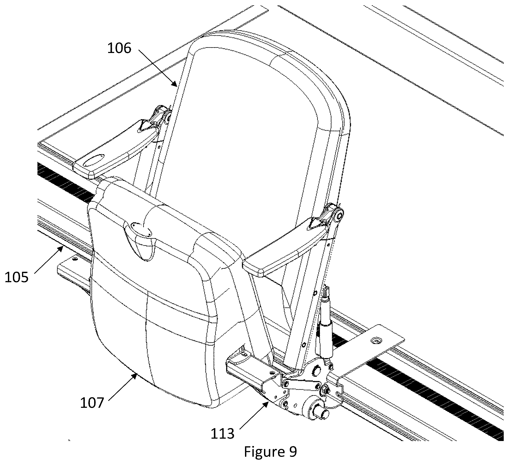
[0024] FIG. 9 is an iso view of a double action nose mounted chair.
[0025] FIG. 10 shows a side view of a double action nose mounted chair in the stored position.
[0026] FIG. 11 shows a side by side comparison showing the clearance gained by using the double action chair.
[0027] FIG. 12 shows multiple rise ranges of the double action nose mount stanchion.
DETAILED DESCRIPTION OF THE INVENTION
[0028] This patent application claims priority from U.S. Provisional Patent Application No. 62/896,667, filed Sep. 6, 2019, the disclosure of which is incorporated by reference herein in its entirety.
[0029] Various embodiments provide a "double action nose mounted stanchion" which serves to allow the seat 107 and mounting brackets 112 to fold down simultaneously with the standard operation of the chair back 106. This allows the entire telescopic platform 102 to slide underneath a balcony 101 or other tight spaces when installed on the top tier of seating. This ensures that the closed dimension of the unit is as small as possible. The design could be used on other tiers, however, the embodiments are discussed with respect to the top tier scenario.
[0030] These embodiments can be used in all folding and telescopic seating structures 102 that recess under a balcony 101 or fit within a tight space that utilize a nose mounted chair 103. These systems are typically installed in school gymnasiums, theaters, arenas or stadiums, but not limited to these venues. An example includes Hussey Seating Company's MXP product line. There are numerous other manufacturers of telescopic seating structures.
[0031] FIGS. 2A and 2B, collectively referred to as FIG. 2, show a telescopic seating structure 102 with a double action chair 104 installed on the top row in both extended (FIG. 2A) and closed (FIG. 2B) configurations.
[0032] FIG. 3 is an isometric view of a typical nose mounted chair 103. These chairs are constructed of three main parts: the back assembly (or back portion) 106, the seat assembly (or seat portion) 107 and the stanchions 108 (commonly referred to as standards). For a nose mounted chair 103, the stanchions 108 are the components that will attach the chair 103 to the platform 102 and dictate the seat height and back pitch of the chair. A stanchion 108 is comprised of two main components: the bracket 112 and the stanchion tube 110. The bracket 112 is used to attach the stanchion 108 to the nose 105 of the platform 102 and to attach the seat 107 to the stanchion 108. The stanchion tube 110 attaches to the bracket 112 with a shaft and provides an attachment location for the back assembly 106 and the armrest. The nose mount stanchion 108 allows for a latch 111 to rotate about the locking shaft 109 and release the back assembly 106 and stanchion tube 110 to rotate backwards so as to lay flat on the deck of the platform 102. The standard operation of a nose mount stanchion 108 can be seen in FIG. 5 and FIG. 6. FIGS. 5A and 5B, collectively referred to as FIG. 5, illustrate cut views showing how a standard nose mounted stanchion 108 unlocks in both a locked (FIG. 5A) and unlocked (FIG. 5B) configurations. FIGS. 6A and 6B, collectively referred to as FIG. 6, illustrate a standard nose mount stanchions 108 positioned for use (FIG. 6A) and storage (FIG. 6B).
[0033] With a standard nose mounted stanchion 108 only the stanchion tube 110 will rotate. This means that the seat 107 will stay fixed and this will cause it to be the highest component on the platform 102 when installed on the last tier of the unit as shown in FIG. 4 a side view of a standard nose mounted chair 103 in the stored position.
[0034] With the double action nose mount stanchion 113, the operation of the stanchion, the back pitch, seat height, and installation method are all held constant. However, with this design the seat assembly 107 rotates forward while the back assembly 106 is being rotated to the stored position. To achieve this the nose mount stanchion 108 is separated into four components: the front bracket 114, the rear bracket 115, pivot straps 116 and the stanchion tube (which may also be referred to as a backrest tube or armrest tube) 110.
[0035] FIGS. 7A and 7B, collectively referred to as FIG. 7, illustrate an embodiment of a "Double Action" stanchion 113 positioned for use (FIG. 7A) and storage (FIG. 7B). The front bracket 114 is where the seat attaches to when the stanchion 113 is assembled. This component has a thick steel plate that is used to fit between the side plates 120 of the rear bracket 115, this is what the front bracket 114 pivots on when operating. The rear bracket 115 is used to attach the stanchion 113 to the nose 105 of the platform 102. These side plates 120 also have two very precisely located curved slots that arc around the pivot location for the stanchion tube 110. One change to stanchion tube 110 from the standard one is a precisely located hole in the stanchion tube center plate 119 to align with the slots found in the rear bracket 115. The pivot straps 116 connect the stanchion tube 110, the rear bracket 115 and the front bracket 114 together.
[0036] With these three components (front bracket 114, rear bracket 115 and stanchion tube 110) of the double action stanchion 113 linked together by the fourth component (the pivot strap 116), the double action stanchion 113 can have both the stanchion tube 110 and front bracket 114 rotate together simultaneously see FIG. 8 which shows a detailed cut view showing internal components of a double action stanchion 113. This is achieved by having a pin 118 that goes through a hole in the pivot strap 116, the slots on both side plates 120 of the rear bracket 115, and the hole in the stanchion tube 110. When the stanchion tube 110 is unlocked and the back assembly 106 is being rotated to the stored position, the pin 118 travels in the slots and pushes the pivot straps 116 and the front bracket 114 forward. This causes the front bracket 114 and seat assembly 107 to rotate around the pivot pin 117 that attaches the front bracket 114 to the rear bracket 115.
[0037] To bring the chairs back to the used position, the back assemblies 106 must be rotated forward as is standard with a nose mounted chair. As the pin 118 travels back through the slot in the rear bracket 115 it pulls on the pivot straps 116 thus pulling the front bracket 114 and seat assembly 107 back into the used position. FIG. 9 is an isometric view of a double action nose mounted chair 104 and FIG. 10 shows a side view of a double action nose mounted chair 104 in the stored position. Together FIG. 9 and FIG. 10 provide views of the double action chair 104 in its stored and used positions respectively.
[0038] The exact geometry of the pivot straps 116, rear bracket 115 and front bracket 114 may depend on the given rise that the chair is being installed on. Splitting the bracket 112 into two (a front 114 and rear bracket 115) keeps the same overall dimensions and can be applied to any rise stanchion to make it into a double action stanchion 113. FIG. 12 shows multiple rise ranges of the double action nose mount stanchion 113.
[0039] The foregoing description has been directed to particular embodiments. However, other variations and modifications may be made to the described embodiments, with the attainment of some or all of their advantages. Modifications to the above-described systems and methods may be made without departing from the concepts disclosed herein. Accordingly, the invention should not be viewed as limited by the disclosed embodiments. Furthermore, various features of the described embodiments may be used without the corresponding use of other features. Thus, this description should be read as merely illustrative of various principles, and not in limitation of the invention.
* * * * *
D00000
D00001
D00002
D00003
D00004
D00005
D00006
D00007
D00008
D00009
D00010
D00011
XML
uspto.report is an independent third-party trademark research tool that is not affiliated, endorsed, or sponsored by the United States Patent and Trademark Office (USPTO) or any other governmental organization. The information provided by uspto.report is based on publicly available data at the time of writing and is intended for informational purposes only.
While we strive to provide accurate and up-to-date information, we do not guarantee the accuracy, completeness, reliability, or suitability of the information displayed on this site. The use of this site is at your own risk. Any reliance you place on such information is therefore strictly at your own risk.
All official trademark data, including owner information, should be verified by visiting the official USPTO website at www.uspto.gov. This site is not intended to replace professional legal advice and should not be used as a substitute for consulting with a legal professional who is knowledgeable about trademark law.