Optical System Including Light-guide Optical Element With Partially-reflective Internal Surfaces
RONEN; Eitan
U.S. patent application number 16/980527 was filed with the patent office on 2021-03-04 for optical system including light-guide optical element with partially-reflective internal surfaces. The applicant listed for this patent is Lumus Ltd.. Invention is credited to Eitan RONEN.
| Application Number | 20210063733 16/980527 |
| Document ID | / |
| Family ID | 1000005238141 |
| Filed Date | 2021-03-04 |
| United States Patent Application | 20210063733 |
| Kind Code | A1 |
| RONEN; Eitan | March 4, 2021 |
OPTICAL SYSTEM INCLUDING LIGHT-GUIDE OPTICAL ELEMENT WITH PARTIALLY-REFLECTIVE INTERNAL SURFACES
Abstract
An optical system includes a light-guide optical element (LOE) (100) having a pair of parallel major external surfaces (102, 104) and a set of mutually-parallel reflector surfaces (106a, 106b, 106c) obliquely angled within the LOE. At least one of the reflector surfaces has high reflectivity for angles of incidence above 60 degrees to the normal and partial reflectivity for angles of incidence less than 35 degrees to the normal.
| Inventors: | RONEN; Eitan; (Rechovot, IL) | ||||||||||
| Applicant: |
|
||||||||||
|---|---|---|---|---|---|---|---|---|---|---|---|
| Family ID: | 1000005238141 | ||||||||||
| Appl. No.: | 16/980527 | ||||||||||
| Filed: | May 23, 2019 | ||||||||||
| PCT Filed: | May 23, 2019 | ||||||||||
| PCT NO: | PCT/IB2019/054272 | ||||||||||
| 371 Date: | September 14, 2020 |
Related U.S. Patent Documents
| Application Number | Filing Date | Patent Number | ||
|---|---|---|---|---|
| 62675205 | May 23, 2018 | |||
| Current U.S. Class: | 1/1 |
| Current CPC Class: | G02B 27/0081 20130101; G02B 27/0101 20130101; G02B 2027/0123 20130101; G02B 6/0055 20130101; G02B 6/327 20130101; G02B 6/0065 20130101 |
| International Class: | G02B 27/00 20060101 G02B027/00; F21V 8/00 20060101 F21V008/00; G02B 27/01 20060101 G02B027/01; G02B 6/32 20060101 G02B006/32 |
Claims
1. An optical system comprising: (a) a light-guide optical element (LOE) having a pair of parallel major external surfaces; and (b) a plurality of mutuahy-parahel reflector surfaces within said LOE, said reflector surfaces being obliquely angled relative to said major external surfaces, wherein at least one of said reflector surfaces is configured to have high reflectivity for angles of incidence above 60 degrees to the normal and partial reflectivity for angles of incidence less than 35 degrees to the normal.
2. The optical system of claim 1, wherein said high reflectivity is in excess of 95% for angles of incidence above 60 degrees.
3. The optical system of claim 1, wherein said partial reflectivity is no more than 50%.
4. The optical system of claim 1, wherein said LOE has a coupling-in region from which coupled-in image illumination propagates along the LOE, and wherein said partial reflectivity varies between successive reflector surfaces so as to at least partially compensate for a decreasing intensity of said image illumination reaching successive reflector surfaces.
5. The optical system of claim 1, wherein said plurality of mutually-parallel reflector surfaces within said LOE further comprises a coupling-in reflector surface that forms at least part of a coupling-in arrangement, said coupling-in reflector surface having high reflectivity for angles of incidence above 60 degrees to the normal and reflectivity of at least about 66% for angles of incidence less than 35 degrees to the normal.
6. The optical system of claim 5, wherein said plurality of reflector surfaces including said coupling-in reflector surface are part of a symmetrical arrangement of two sets of mutually-parallel reflector surfaces including two coupling-in reflector surfaces, said two coupling-in reflector surfaces meeting to form a chevron coupling-in arrangement.
7. The optical system of claim 1, further comprising an image projector projecting a collimated image, and wherein a coupling-in arrangement optically couples said collimated image into said LOE as first-order image illumination so as to propagate within said LOE by internal reflection at said major faces, said first-order image illumination spanning a first angular field of view, said first angular field of view being at steeper angles to said major surfaces than said reflector surfaces.
8. The optical system of claim 7, wherein at least part of said first-order image illumination propagating along said LOE is transmitted and then reflected by one of said reflector surfaces to generate second-order image illumination spanning a second angular field of view at shallower angles to said major surfaces than said reflector surfaces.
9. The optical system of claim 8, wherein said second-order image illumination is deflected back to first-order image illumination by reflection in a subsequent one of said reflector surfaces.
10. The optical system claim 1, wherein said reflector surfaces are inclined at an angle of 20.degree.-26.degree. to said major external surfaces of said LOE.
11. The optical system claim 1, wherein said reflector surfaces are inclined at an angle of 23.degree.-25.degree. to said major external surfaces of said LOE.
12. The optical system of claim 2, wherein said partial reflectivity is no more than 50%.
Description
FIELD AND BACKGROUND OF THE INVENTION
[0001] The present invention relates to optical systems for use in head-up displays and, in particular, it concerns an optical system employing a light-guide optical element (LOE) with partially-reflective internal surfaces.
[0002] Various displays, particularly head-up displays (HUD) and near-eye displays for augmented reality or virtual reality, employ light-guide optical elements (LOEs) having a pair of parallel major external surfaces to convey a collimated image which propagates within the LOE by internal reflection. The image is gradually coupled-out from the LOE, typically either directly towards the eye or into another LOE which conveys the image to the eye. In one class of such devices, coupling-out of the image from the LOE is achieved by a set of mutually-parallel partially-reflecting surfaces within the LOE, deployed obliquely relative to the major external surfaces of the LOE. The gradual coupling-out over a series of partially-reflecting surfaces achieves multiplication of the optical aperture that was coupled into the LOE.
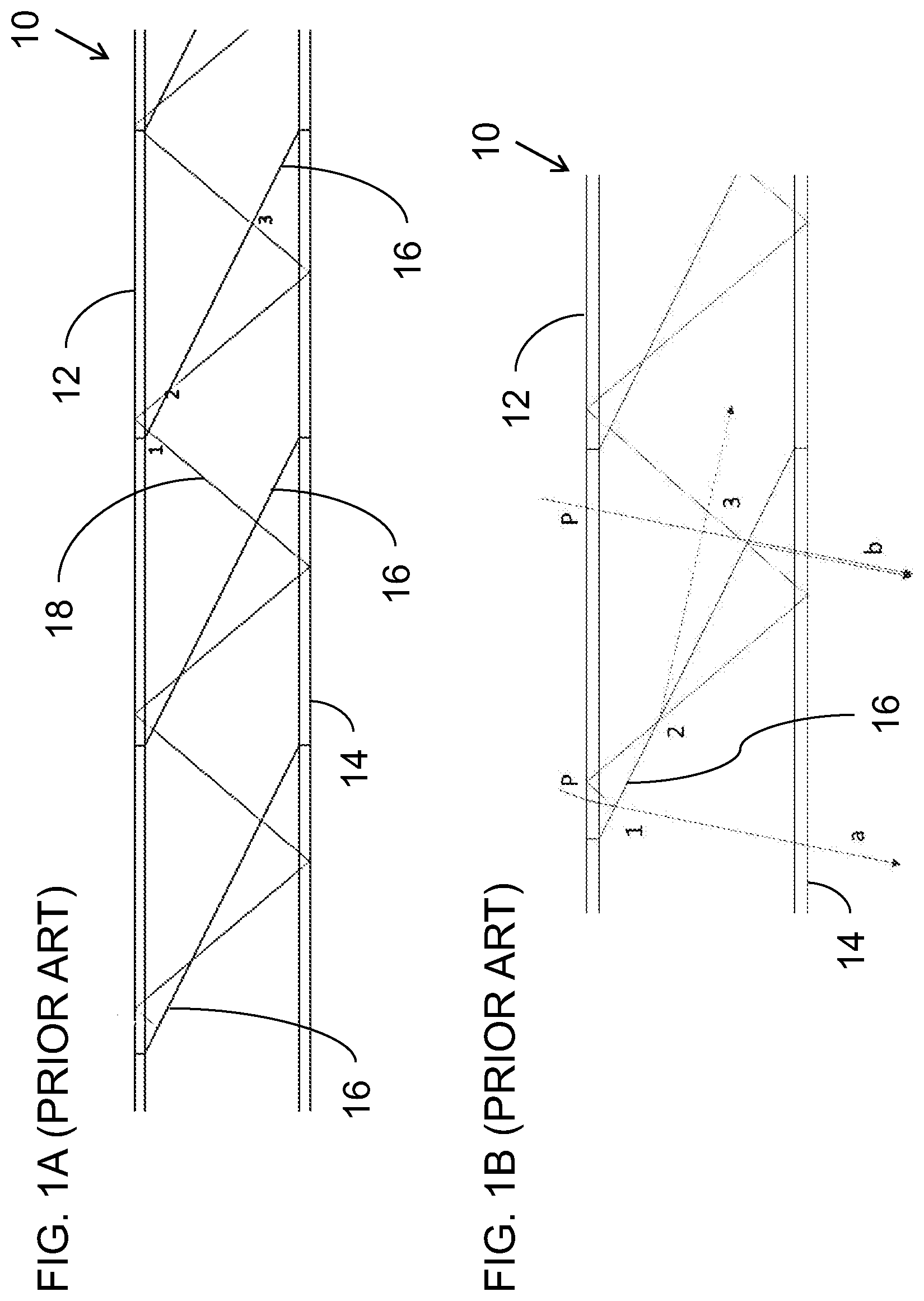
[0003] Conventional LOEs impose stringent requirements on reflectivity of the partially-reflecting surfaces as a function of incident angle, typically requiring high transmission (near complete transmission) of image illumination at certain ranges of angles, and partial reflection at other angles relative to the plane of the facets. In practice, it is difficult to achieve near-complete transmission. One typical example is illustrated schematically in FIGS. 1A and 1B in which an LOE 10 with parallel major surfaces 12, 14 includes a set of partially-reflecting surfaces 16 (also referred to interchangeably herein as "facets"). An exemplary ray of light 18, at an angle corresponding to a given pixel of the image generated from a given location in the input optical aperture (not shown), propagates along the LOE by internal reflection at surfaces 12 and 14.
[0004] In a typical application, the image illumination exemplified by ray 18 propagates at a steeper angle to the major surfaces 12, 14 than the angle of the partially-reflecting surfaces 16. As a result, each illumination ray 18 may cross a given facet 16 several times. For instance, in FIGS. 1A and 1B, as ray 18 propagates from left to right, it crosses the third facet three times, at locations denoted 1, 2 and 3, respectively. As a result, the light reflected and coupled-out from point 1 (denoted a in FIG. 1B) will be stronger than that reflected and coupled-out from point 3 (denoted b), resulting in a non-uniformity in the output image.
[0005] Additionally, it is typically required that the facet be transparent (no reflection) for ray 18 at the angle of incidence shown at location 2, since any reflection there (dotted arrow) will further decrease the brightness of propagating light reaching point 3, and will generate a "ghost" due to illumination propagating in the wrong direction, which may result in part of the image appearing misplaced in the final image. This requirement for full transparency (zero reflection) is difficult to achieve, and becomes increasingly difficult to fulfill as the angles of incidence (AO') get larger.
SUMMARY OF THE INVENTION
[0006] The present invention is an optical system including a light-guide optical element (LOE) with internal reflector surfaces.
[0007] According to the teachings of an embodiment of the present invention there is provided, an optical system comprising: (a) a light-guide optical element (LOE) having a pair of parallel major external surfaces; and (b) a plurality of mutually-parallel reflector surfaces within the LOE, the reflector surfaces being obliquely angled relative to the major external surfaces, wherein at least one of the reflector surfaces is configured to have high reflectivity for angles of incidence above 60 degrees to the normal and partial reflectivity for angles of incidence less than 35 degrees to the normal.
[0008] According to a further feature of an embodiment of the present invention, the high reflectivity is in excess of 95% for angles of incidence above 60 degrees.
[0009] According to a further feature of an embodiment of the present invention, the partial reflectivity is no more than 50%.
[0010] According to a further feature of an embodiment of the present invention, the LOE has a coupling-in region from which coupled-in image illumination propagates along the LOE, and wherein the partial reflectivity varies between successive reflector surfaces so as to at least partially compensate for a decreasing intensity of the image illumination reaching successive reflector surfaces.
[0011] According to a further feature of an embodiment of the present invention, the plurality of mutually-parallel reflector surfaces within the LOE further comprises a coupling-in reflector surface that forms at least part of a coupling-in arrangement, the coupling-in reflector surface having high reflectivity for angles of incidence above 60 degrees to the normal and reflectivity of at least about 66% for angles of incidence less than 35 degrees to the normal.
[0012] According to a further feature of an embodiment of the present invention, the plurality of reflector surfaces including the coupling-in reflector surface are part of a symmetrical arrangement of two sets of mutually-parallel reflector surfaces including two coupling-in reflector surfaces, the two coupling-in reflector surfaces meeting to form a chevron coupling-in arrangement.
[0013] According to a further feature of an embodiment of the present invention, there is also provided an image projector projecting a collimated image, and wherein a coupling-in arrangement optically couples the collimated image into the LOE as first-order image illumination so as to propagate within the LOE by internal reflection at the major faces, the first-order image illumination spanning a first angular field of view, the first angular field of view being at steeper angles to the major surfaces than the reflector surfaces.
[0014] According to a further feature of an embodiment of the present invention, at least part of the first-order image illumination propagating along the LOE is transmitted and then reflected by one of the reflector surfaces to generate second-order image illumination spanning a second angular field of view at shallower angles to the major surfaces than the reflector surfaces.
[0015] According to a further feature of an embodiment of the present invention, the second-order image illumination is deflected back to first-order image illumination by reflection in a subsequent one of the reflector surfaces.
[0016] According to a further feature of an embodiment of the present invention, the reflector surfaces are inclined at an angle of 20.degree.-26.degree., and preferably at an angle of 23.degree.-25.degree., to the major external surfaces of the LOE.
[0017] For the purpose of defining angles of incidence of a ray incident on a plane, the angle of incidence is defined as the angle between the ray direction and a normal to the plane, such that a ray perpendicular to a surface has an angle of incidence referred to as 0.degree. while an angle approaching 90.degree. is grazing incidence. Unless otherwise specified, the phrase "small angles of incidence" refers to angles of 0.degree.-35.degree. while "large angles of incidence" refers to angles of 60.degree.-90.degree..
[0018] The terms "steep" or "steeper" are used to refer to rays with relatively small angles of incidence to a plane, or to a plane which is inclined at a relatively large angle to the reference plane. Conversely, "shallow" or "shallower" are used to refer to relatively large-angle rays that are nearer to grazing incidence, or to a plane which is inclined at a relatively small angle to the reference plane.
BRIEF DESCRIPTION OF THE DRAWINGS
[0019] The invention is herein described, by way of example only, with reference to the accompanying drawings, wherein:
[0020] FIGS. 1A and 1B, discussed above, are schematic side views showing the geometry of a ray of light propagating along an LOE and a set of obliquely oriented partially-reflective surfaces within the LOE according to certain conventional LOE designs;
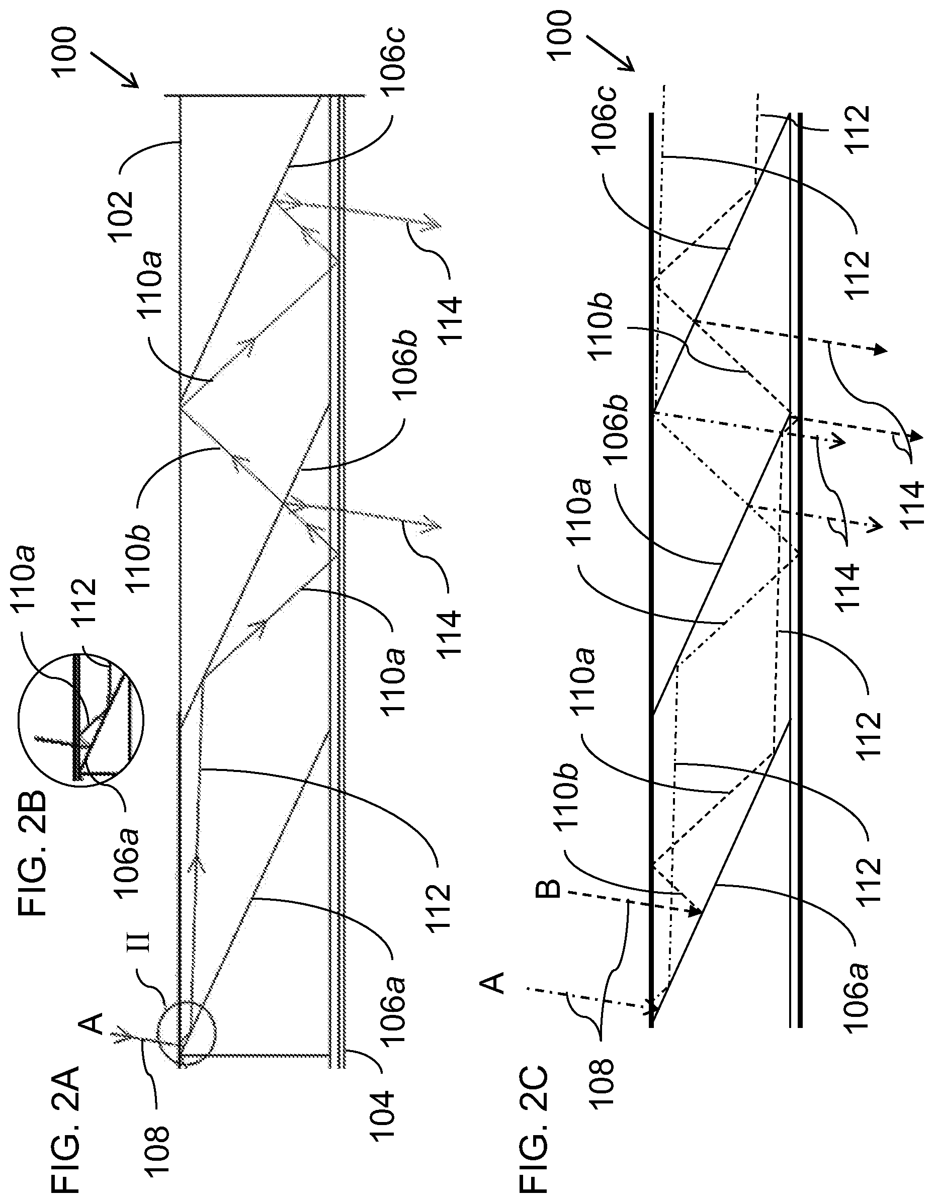
[0021] FIGS. 2A, 2C, 2D and 2E are schematic side views of an LOE constructed and operative according to the teachings of an embodiment of the present invention, illustrating various ray paths for rays of an image propagating along the LOE;
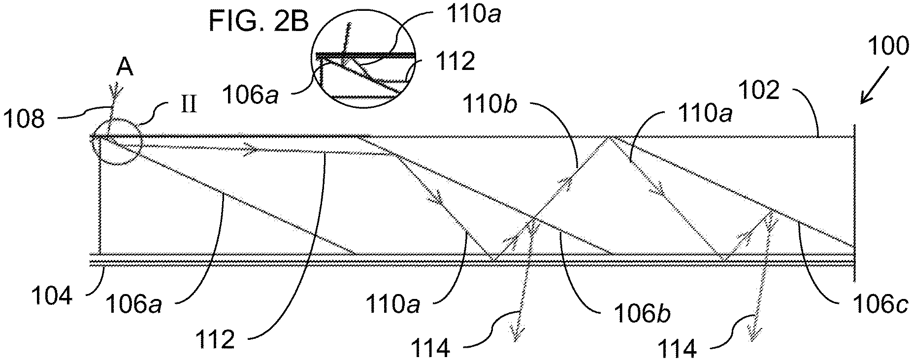
[0022] FIG. 2B is an enlarged view of the region of FIG. 2A indicated by a circle designated II; and
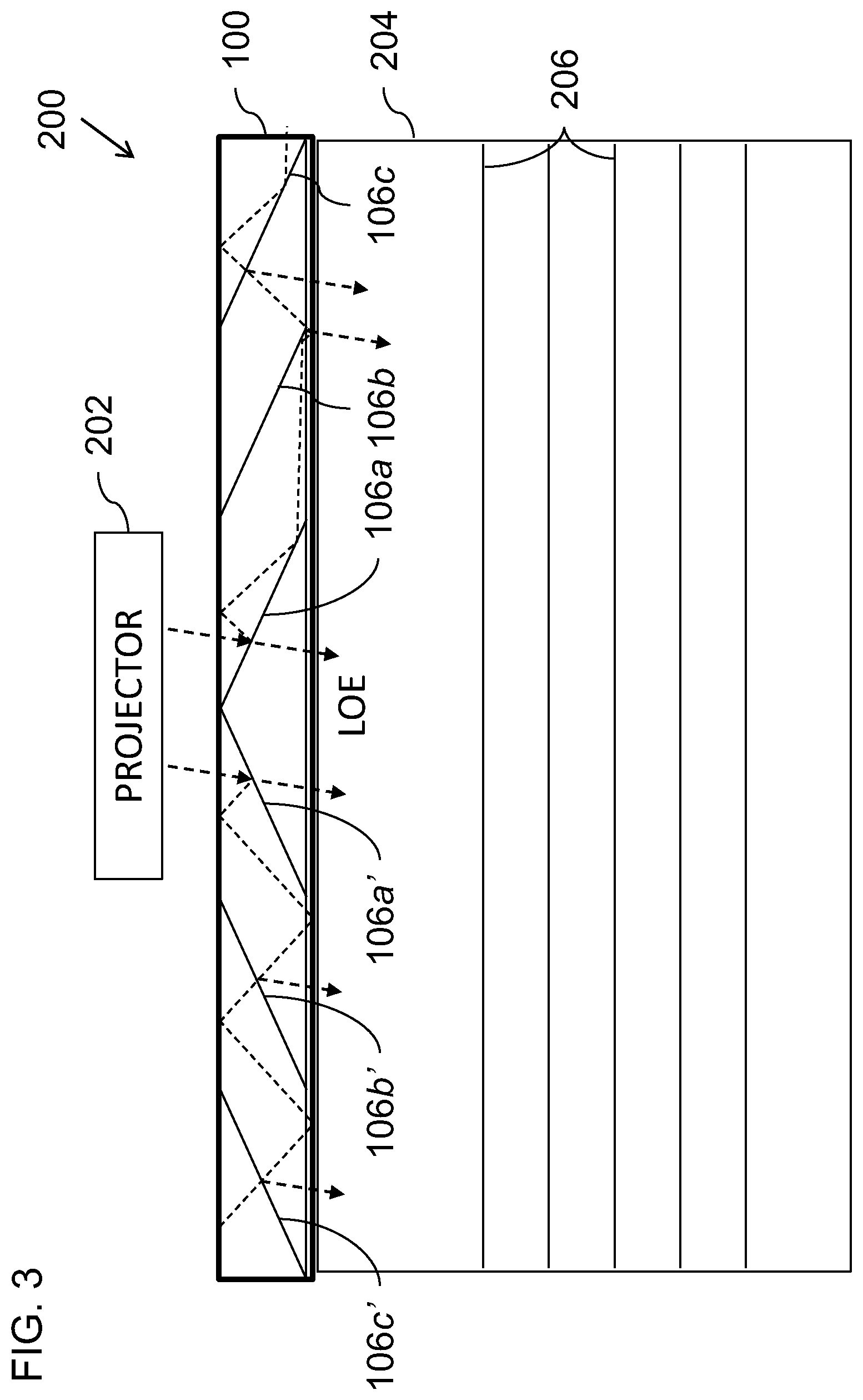
[0023] FIG. 3 is a schematic view of an optical system employing the LOE of FIGS. 2A-2E to provide a near-eye display.
DESCRIPTION OF THE PREFERRED EMBODIMENTS
[0024] The present invention is an optical system including a light-guide optical element.
[0025] The principles and operation of optical systems according to the present invention may be better understood with reference to the drawings and the accompanying description.
[0026] Referring now to the drawings, FIGS. 2A-2E are schematic illustrations of a basic implementation of part of an optical system including a light-guide optical element (LOE) 100 having a pair of parallel major external surfaces 102 and 104. A plurality of mutually-parallel reflector surfaces 106a, 106b and 106c are deployed within LOE 100, obliquely angled relative to major external surfaces 102 and 104.
[0027] It is a particular feature of certain particularly preferred implementations of the present invention that at least one of the reflector surfaces 106b, 106c is configured to have high reflectivity for angles of incidence above 60 degrees to the normal and partial reflectivity for angles of incidence less than 35 degrees to the normal. "High reflectivity" in this context is generally taken to mean reflectivity above 90%, and more preferably in excess of 95%. In some particularly preferred implementations, the high reflectivity achieved for incident angles above 60 degrees is above 98%, and most preferably close to 100%. Unlike the prior art approaches described above, this aspect of the present invention does not require the reflector surfaces to have near-zero reflectivity at any range of incident angles. This greatly simplifies implementation of the multi-layer dielectric coatings or other reflective coatings applied to the reflector surfaces.
[0028] The use of reflector surfaces that are highly reflective at large angles generates distinctive ray paths that differ from those of the prior art. Specifically, referring to the ray paths illustrated in FIGS. 2A and 2C-2E, as well as in the enlargement of FIG. 2B, a collimated image delivered to the LOE (exemplified by injected rays 108 in various different positions across the aperture, labeled A, B, C, D and E) is coupled into the LOE as first-order image illumination, exemplified by image rays 110a and their conjugate image rays 110b so as to propagate within LOE 100 by internal reflection at the major faces 102, 104. The illustrated rays A-E are all parallel which, in a collimated image, indicates that they all correspond to illumination from a single pixel of the injected image, where the total field of view (FOV) of the coupled-in image, referred to here as "first-order image illumination," spans a first angular field of view. This first angular field of view is directed at steeper angles to the major surfaces than the reflector surfaces 106a, 106b, 106c. As a result of this steeper angle of the first angular field of view, at least part of the first-order image illumination propagating along the LOE undergoes reflection at large incident angle by one of the reflector surfaces, deflecting rays 110a to generate second-order image illumination, exemplified by ray 112, spanning a second angular field of view at shallower angles to the major surfaces 102, 104 than the reflector surfaces 106a, 106b, 106c. When ray 112 impinges on the next reflector surface, the second-order image illumination 112 is deflected back to first-order image illumination 110a by reflection in a subsequent one of the reflector surfaces. When rays 110b impinge on the reflector surfaces, this occurs at small angles (less than 35 degrees), resulting in partial reflection for coupling out image illumination as rays 114, as well as partial transmission of rays 110b which carries forward part of the illumination intensity for coupling-out further along the LOE.
[0029] In the non-limiting example illustrated here, coupling-in of image rays 108 is achieved using reflector surface 106a which is implemented as a coupling-in reflector surface with high reflectivity for angles of incidence above 60 degrees to the normal and more than 50% reflectivity, typically at least about 66%, for angles of incidence less than 35 degrees to the normal. A first reflection in facet 106a thus couples-in the image illumination to first-order image illumination 110b. Rays A and B illustrated in FIGS. 2A-2C enter in a region of the input aperture and at an angle that leads to them being reflected a second time from facet 106a, resulting in second-order image illumination 112, which is converted back to first-order image illumination 110a at facet 106b. That first-order image illumination then reflects from major surface 104 to become 106a which traverses facet 106b while generating coupled-out rays 114 by partial reflection. Rays A and B continue to propagate along the LOE, also traversing facet 106c where further partial reflection occurs, and then undergo an additional large-angle reflection at facet 106c to repeat the above process. Since the reflectivity of the reflector surfaces at large angles is high, the conversion to and from second-order image illumination occurs without significant losses of energy or generation of ghost images. Additionally, the use of relatively shallow-angle reflector surfaces facilitates implementation of a relatively thin and light-weight LOE. Preferred inclination of the reflector surfaces relative to the major surfaces of the LOE is between 20.degree.-26.degree., and most preferably 23.degree.-25.degree..
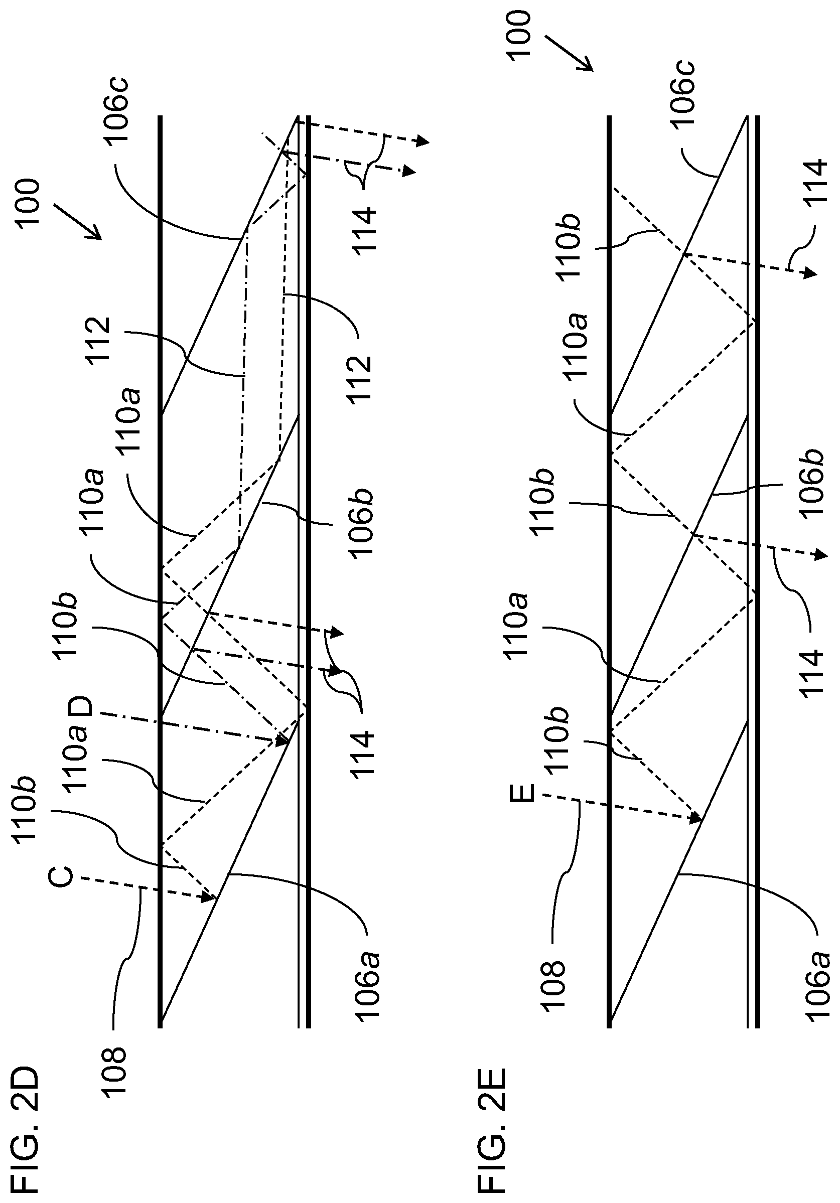
[0030] It will be noted that different rays undergo the above conversion between first- and second-order image illumination at different locations, and in some cases, not at all. Thus, FIG. 2D illustrates rays C and D which undergo regular first-order image illumination propagation between facets 106a and 106b, and then undergo conversion to second-order illumination by reflection on the rear face of second reflector surface 106b. FIG. 2E illustrates a ray E for which the position and angle of the coupled-in ray is such that the ray remains as first-order image illumination over the span of the three facets illustrated here.
[0031] These various different types of optical paths provide coupling out of the image illumination from the LOE in a range of locations along the LOE, and typically cooperate to generate a generally continuous overall image output over a desired output area. The partial reflectivity of the reflector surfaces at small angles are preferably varied between the surfaces in order to enhance uniformity of the output image, according to the following principles. Firstly, where a first facet 106a is used as a coupling-in surface, the reflectivity for the coupling-in reflector surface is preferably at least 50%, and is most preferably roughly (1-1/n) where n is the number of facets, unless the coupling-in reflector surface is outside the region in which coupling-out is required, in which case a 100% reflector can be used.
[0032] The small-angle partial reflectivity of the remaining facets is preferably roughly 1/n where n for each facet is the number of remaining facets at which coupling-out is required, including the current facet. Thus, for example, in the case of a 3 facet implementation as shown, optimal reflectivity values for the facets at small and large angles would be as follows:
TABLE-US-00001 Facet Number Reflectivity at small angles Reflectivity at large angles 1 66% >98% 2 50% >98% 3 100% >98%
and for a 4 facet implementation would be as follows:
TABLE-US-00002 Facet Number Reflectivity at small angles Reflectivity at large angles 1 75% >98% 2 33% >98% 3 50% >98% 4 100% >98%
[0033] The above properties can readily be achieved using standard software tools for designing multi-layer coatings and, in fact, can be achieved more uniformly and require fewer coating layers than the aforementioned conventional designs having requirements of non-reflective properties for certain angular ranges.
[0034] The above exemplary reflectance values are suitable for implementations in which the LOE is used for a first dimension of optical aperture expansion that serves as the input to another LOE which is opposite the eye, or for virtual reality applications. For applications in which the LOE is deployed opposite the eye for augmented reality applications, the coupling-in facet is deployed outside the field of view (or an alternative coupling-in configuration is used), and a larger number of facets with relatively low reflectivity at small angles is preferred.
[0035] FIG. 3 illustrates schematically an overall optical system 200 which includes an image projector 202 configured to project a collimated image. The image projector 202 is shown here only schematically, and can be any type of projector that projects a collimated image. In some embodiments, the image projector includes a light source, a spatial light modulator (such as a liquid crystal on silicon, or "LCOS") and collimating optics. These components may advantageously be arranged on surfaces of a number of beam splitter prisms, for example, polarized beam splitter (PBS) cubes, with reflective collimating optics, all as is known in the art.
[0036] A coupling-in arrangement, such as first facets 106a, optically couples the collimated image into the LOE as first-order image illumination so as to propagate within the LOE, with interchange between the first- and second-order image illumination and progressive coupling-out of the image, all as described above. In one particularly preferred but non-limiting implementation as illustrated here, the set of reflector surfaces 106a, 106b and 106c are part of a symmetrical arrangement of two sets of mutually-parallel reflector surfaces 106a, 106b, 106c, 106a', 106b' and 106c' including two coupling-in reflector surfaces 106a and 106a' which meet to form a chevron coupling-in arrangement.
[0037] The coupled-out image illumination from LOE 100 is shown here schematically coupled-in to a further LOE 204 which conveys the image opposite the eye of the observer and couples it out towards the observer's eye. LOE 204 may be implemented with facets 206 that are implemented according to the teachings of the present invention, with high reflectivity at large angles, or may be implemented using otherwise conventional LOE technology based on partially-reflective facets and/or diffractive optical elements for coupling-in and coupling-out, as is known in the art.
[0038] Although coupling of the projected image into the LOE has been exemplified herein with reference to a coupling-in reflector surface, it will be appreciated that other coupling in arrangements can also be used to advantage. Additional options include, but are not limited to, various forms of coupling-in prism, attached to or integrated with one of the major surfaces and/or with a side surface of the LOE, which provides a correctly angled surface for direct injection of a projected image into a guided first-order image illumination mode, and various coupling-in arrangements based on diffractive optical elements.
[0039] Additional features may optionally be implemented in combination with the features described thus far in order to further enhance uniformity of the coupled-out image intensity across the exit aperture. According to one non-limiting example, one or both of the major surfaces of the LOE is modified by addition of a parallel-faced plate optically bonded to the LOE, and with a partially-reflecting interface between the LOE and the plate, generated either by introduction of an interface layer of suitable material or by applying suitable coatings to one or both surfaces at the interface. This partially-reflecting interface serves as a "mixer", generating overlap of multiple optical paths, thereby enhancing uniformity of the coupled-out image intensity across the exit aperture of the LOE.
[0040] It will be appreciated that the above descriptions are intended only to serve as examples, and that many other embodiments are possible within the scope of the present invention as defined in the appended claims.
* * * * *
D00000
D00001
D00002
D00003
D00004
XML
uspto.report is an independent third-party trademark research tool that is not affiliated, endorsed, or sponsored by the United States Patent and Trademark Office (USPTO) or any other governmental organization. The information provided by uspto.report is based on publicly available data at the time of writing and is intended for informational purposes only.
While we strive to provide accurate and up-to-date information, we do not guarantee the accuracy, completeness, reliability, or suitability of the information displayed on this site. The use of this site is at your own risk. Any reliance you place on such information is therefore strictly at your own risk.
All official trademark data, including owner information, should be verified by visiting the official USPTO website at www.uspto.gov. This site is not intended to replace professional legal advice and should not be used as a substitute for consulting with a legal professional who is knowledgeable about trademark law.