Powered Hinge Assembly For Vehicle Doors
Bakos; Tracy Christopher ; et al.
U.S. patent application number 16/555055 was filed with the patent office on 2021-03-04 for powered hinge assembly for vehicle doors. This patent application is currently assigned to Ford Global Technologies, LLC. The applicant listed for this patent is Ford Global Technologies, LLC. Invention is credited to Tracy Christopher Bakos, Kristopher Karl Brown, Larry Dean Elie, Suresh Narayan, Paul Repp.
| Application Number | 20210062566 16/555055 |
| Document ID | / |
| Family ID | 1000004301464 |
| Filed Date | 2021-03-04 |


| United States Patent Application | 20210062566 |
| Kind Code | A1 |
| Bakos; Tracy Christopher ; et al. | March 4, 2021 |
POWERED HINGE ASSEMBLY FOR VEHICLE DOORS
Abstract
An automated door system includes a hinge assembly having a movable hinge portion coupled to a door and a fixed hinge portion coupled to a vehicle body at a hinge pillar. The movable hinge portion includes first and second mounting portions. The first mounting portion is rotatably connected to the fixed hinge portion for rotation about a hinge axis of the hinge assembly. A power assist device is coupled to the fixed hinge portion and further coupled to the second mounting portion of the mounting hinge portion by a drive shaft. The power assist device includes a motor that is configured to drive the drive shaft for providing at least one of opening and closing movement of the door about the hinge axis of the hinge assembly.
| Inventors: | Bakos; Tracy Christopher; (Commerce, MI) ; Narayan; Suresh; (Pinckney, MI) ; Brown; Kristopher Karl; (Dearborn, MI) ; Repp; Paul; (Plymouth, MI) ; Elie; Larry Dean; (Ypsilanti, MI) | ||||||||||
| Applicant: |
|
||||||||||
|---|---|---|---|---|---|---|---|---|---|---|---|
| Assignee: | Ford Global Technologies,
LLC Dearborn MI |
||||||||||
| Family ID: | 1000004301464 | ||||||||||
| Appl. No.: | 16/555055 | ||||||||||
| Filed: | August 29, 2019 |
| Current U.S. Class: | 1/1 |
| Current CPC Class: | E05Y 2201/434 20130101; E05F 15/614 20150115; B60J 5/047 20130101; E05F 15/70 20150115; E05Y 2900/531 20130101 |
| International Class: | E05F 15/614 20060101 E05F015/614; E05F 15/70 20060101 E05F015/70; B60J 5/04 20060101 B60J005/04 |
Claims
1. An automated door system, comprising: a door pivotally coupled to a vehicle body by at least one hinge assembly, the hinge assembly including a movable hinge portion having a base coupled to the door and a fixed hinge portion coupled to the vehicle body at a hinge pillar, wherein the movable hinge portion includes vertically spaced-apart upper and lower mounting portions, and wherein the upper mounting portion is rotatably connected to the fixed hinge portion for a rotation about a hinge axis of the hinge assembly; a power assist device coupled to the fixed hinge portion and further coupled to the lower mounting portion of the movable hinge portion by a drive shaft extending outwardly from the power assist device, wherein the drive shaft rotates about a motor axis that is coaxial with the hinge axis; and a motor disposed within the power assist device and configured to drive the drive shaft for providing at least one of opening and closing movement of the door about the hinge axis of the hinge assembly.
2. The automated door system of claim 1, wherein: the upper mounting portion of the movable hinge portion is rotatably connected to the fixed hinge portion via a hinge pin.
3. The automated door system of claim 1, wherein: the motor includes one of an electric motor, a power winch, an actuator, a servo motor, an electric solenoid, a pneumatic cylinder, and a hydraulic cylinder.
4. The automated door system of claim 1, wherein: the door includes an inner panel having a first sidewall with the base of the movable hinge portion coupled thereto.
5. The automated door system of claim 1, wherein: the motor is configured to provide both opening and closing movement of the door.
6. The automated door system of claim 1, wherein: the base of the mounting hinge portion comprises an upright web, and the upper and lower mounting portions extend transversely from the upright web.
7. The automated door system of claim 1, wherein: the power assist device is configured to move the door between a closed position and a plurality of open positions disposed along a door swing path.
8. The automated door system of claim 1, wherein: the power assist device is configured to move the door to a predetermined detent position and retain the door at the detent position.
9. The automated door system of claim 1, wherein: the power assist device is configured provide a soft close feature for the door when an initial velocity of the door exceeds a threshold velocity in a door closing movement along a door swing path.
10. The automated door system of claim 1, wherein: the drive shaft extends outwardly from a first end of the power assist device; the power assist device is coupled to the fixed hinge portion by a transverse plate.
11. The automated door system of claim 10, wherein: the fixed hinge portion includes a fixed base portion fixed to the vehicle body and vertically spaced-apart upper and lower connecting portions extending transversely from the fixed base portion, wherein the upper connecting portion is rotatably connected to the upper mounting portion of the mounting hinge portion, and the lower connecting portion is connected to the transverse plate.
12. The automated door system of claim 1, wherein: the hinge pillar includes spaced-apart inner and outer sidewalls, each having bolt-receiving openings therethrough, and a compression tube having opposite ends abutting the inner and outer sidewalls around the bolt-receiving openings; and including: an elongated bolt extending through an opening in a fixed base portion of the fixed hinge portion and through the bolt-receiving openings and through the compression tube, the elongated bolt having an outer end engaging the fixed base portion of the fixed hinge portion and an inner end connected to an instrument panel compensator joint whereby the elongated bolt secures the fixed hinge portion to the hinge pillar and simultaneously secures an instrument panel structure to the hinge pillar.
13. The automated door system of claim 12, wherein: the hinge pillar has upper and lower ends, and the fixed hinge portion is secured to the upper end of the hinge pillar.
14. A motor vehicle comprising: a body with at least one opening; and an automated door system, comprising: a door pivotally coupled to the vehicle body by upper and lower hinge assemblies to selectively close off the opening of the body, the upper hinge assembly including a movable hinge portion having a base coupled to the door and a fixed hinge portion coupled to the vehicle body at a hinge pillar, wherein the movable hinge portion includes vertically spaced-apart upper and lower mounting portions, and wherein the upper mounting portion is rotatably connected to the fixed hinge portion for a rotation about a hinge axis of the upper hinge assembly; a power assist device coupled to the fixed hinge portion and further coupled to the lower mounting portion of the movable hinge portion by a drive shaft extending upwardly from the power assist device; and a motor disposed within the power assist device and configured to drive the drive shaft for providing opening and closing movement of the door about the hinge axis of the hinge assembly.
15. The motor vehicle of claim 14, wherein: the drive shaft rotates about a motor axis that is coaxial with the hinge axis.
16. The motor vehicle of claim 14, wherein: the upper mounting portion of the movable hinge portion is rotatably connected to the fixed hinge portion via a hinge pin.
17. The motor vehicle of claim 14, wherein: the base of the mounting hinge portion comprises an upright web, and the upper and lower mounting portions extend transversely from the upright web.
18. The motor vehicle of claim 14, wherein: the drive shaft extends outwardly and upwardly from an upper end of the power assist device; the power assist device is coupled to the fixed hinge portion by a plate that extends transverse relative to the motor axis.
19. The motor vehicle of claim 14, wherein: the fixed hinge portion includes a fixed base portion fixed to the vehicle body and vertically spaced-apart upper and lower connecting portions extending transversely from the fixed base portion, wherein the upper connecting portion is rotatably connected to the upper mounting portion of the mounting hinge portion, and the lower connecting portion is connected to a transverse plate.
20. A motor vehicle comprising: a body with at least one opening; and an automated door system, comprising: a door pivotally coupled to the vehicle body by at least one hinge assembly, the hinge assembly including a movable hinge portion having a base coupled to the door and a fixed hinge portion having a fixed base portion coupled to the vehicle body at a hinge pillar, wherein the movable hinge portion includes vertically spaced-apart upper and lower mounting portions, and wherein the upper mounting portion is rotatably connected to the fixed hinge portion for a rotation about a hinge axis of the hinge assembly; a power assist device coupled to the fixed hinge portion and further coupled to the lower mounting portion of the movable hinge portion by a drive shaft extending outwardly from the power assist device; a motor disposed within the power assist device and configured to drive the drive shaft for providing at least one of opening and closing movement of the door about the hinge axis of the hinge assembly; wherein the hinge pillar includes spaced-apart inner and outer sidewalls, each having bolt-receiving openings therethrough, and a compression tube having opposite ends abutting inner sides of the inner and outer sidewalls around the bolt-receiving openings; and including: an elongated bolt extending through an opening in a fixed base portion of the fixed hinge portion and through the bolt-receiving openings and through the compression tube, the elongated bolt having an outer end engaging the fixed base portion of the fixed hinge portion and an inner end connected to an instrument panel compensator joint whereby the elongated bolt secures the fixed hinge portion to the hinge pillar and simultaneously secures an instrument panel structure to the hinge pillar.
Description
FIELD OF THE INVENTION
[0001] The present invention generally relates to a device for use on an automotive vehicle door, and more particularly to a power assist device for the vehicle door providing opening and/or closing assistance for the door.
BACKGROUND OF THE INVENTION
[0002] Various powered vehicle doors have been developed. Known vehicle doors may provide for powered opening and/or closing of the vehicle door.
SUMMARY OF THE INVENTION
[0003] One aspect of the present invention is an automated door system including a door pivotally coupled to a vehicle body by at least one hinge assembly. The hinge assembly includes a movable hinge portion having a base coupled to the door and a fixed hinge portion coupled to the vehicle body at a hinge pillar. The movable hinge portion includes vertically spaced-apart upper and lower mounting portions extending from the base. The upper mounting portion is rotatably connected to the fixed hinge portion for rotation about a hinge axis of the hinge assembly. A power assist device is coupled to the fixed hinge portion and further coupled to the lower mounting portion of the mounting hinge portion by a drive shaft extending outwardly from the power assist device. The drive shaft rotates about a motor axis that is coaxial with the hinge axis. A motor is disposed within a power assist device and configured to drive the drive shaft for providing at least one of opening and closing movement of the door about the hinge axis of the hinge assembly.
[0004] Embodiments of the first aspect of the disclosure can include any one or a combination of the following features: [0005] The upper mounting portion of the mounting hinge assembly may be rotatably connected to the fixed hinge portion. [0006] The motor may include one of an electric motor, a power winch, an actuator, a servo motor, an electric solenoid, a pneumatic cylinder, and a hydraulic cylinder. [0007] The door may include an inner panel having a first sidewall with the base of the movable hinge portion coupled thereto. [0008] The motor may be configured to provide both opening and closing movement of the door. [0009] The base of the mounting hinge portion may comprise an upright web, and the upper and lower mounting portions may extend transversely from the upright web. [0010] The power assist device may be configured to move the door between a closed position and a plurality of open positions disposed along a door swing path. [0011] The power assist device may be configured to move the door to a predetermined detent position and retain the door at the detent position. [0012] The power assist device may be configured to provide a soft close feature for the door when an initial velocity of the door exceeds a threshold velocity in a door closing movement along a door swing path. [0013] The drive shaft may extend outwardly from a first end of the power assist device, and the power assist device may be coupled to the fixed hinge portion by a transverse plate. [0014] The fixed hinge portion may include a fixed based portion fixed to the vehicle body and a vertically spaced-apart upper and lower connecting portions extending transversely from the fixed base portion. [0015] The upper connecting portion may be rotatably connected to the upper mounting portion of the mounting hinge portion, and the lower connecting portion may be connected to the transverse plate. [0016] The hinge pillar may include spaced-apart inner and outer sidewalls, each having bolt-receiving openings therethrough. A compression tube may be disposed inside the hinge pillar with opposite ends abutting the inner and outer sidewalls around the bolt-receiving openings. [0017] An elongated bolt may extend through an opening in a fixed base portion of the fixed hinge portion, and through the bolt-receiving openings and through the compression tube. The elongated bolt may have an outer end engaging the fixed based portion of the fixed hinge portion and an inner end connected to an instrument panel compensator joint, where the elongated bolt secures the fixed hinge portion to the hinge pillar and simultaneously secures an instrument panel structure to the hinge pillar. [0018] The hinge pillar may have upper and lower ends, and the fixed hinge portion may be secured to the upper end of the hinge pillar.
[0019] Another aspect of the present disclosure is a motor vehicle including a body with at least one opening and an automated door system. The automated door system includes a door pivotally coupled to the vehicle body by upper and lower hinge assemblies to selectively close off the opening of the body. The upper hinge assembly includes a movable hinge portion having a base coupled to the door and a fixed hinge portion coupled to the vehicle at a hinge pillar. The movable hinge portion includes vertically spaced-apart upper and lower mounting portions. The upper mounting portion is rotatably connected to the fixed hinge portion for rotation about a hinge axis of the upper hinge assembly. A power assist device is coupled to the fixed hinge portion and further coupled to the lower mounting portion of the movable hinge portion by a drive shaft extending upwardly from the power assist device. A motor is disposed within a power assist device, and the motor is configured to drive the drive shaft for providing opening and closing movement of the door about the hinge axis of the hinge assembly.
[0020] Embodiments of the second aspect of the disclosure can include any one or a combination of the following features: [0021] The drive shaft may optionally rotate about a motor axis that is coaxial with the hinge axis. [0022] The upper mounting portion of the movable hinge portion may be rotatably connected to the fixed hinge portion via a hinge pin. [0023] The base of the mounting hinge portion may include an upright web, and the upper and lower mounting portions may extend transversely from the upright web. [0024] The drive shaft may optionally extend outwardly and upwardly from an upper end of the power assist device. [0025] The power assist device is optionally coupled to the fixed hinge portion by a plate that extends transverse relative to the motor axis. [0026] The fixed hinge portion may optionally include a fixed base portion that is fixed to the vehicle body. [0027] The fixed hinge portion may optionally include vertically spaced-apart upper and lower connecting portions extending transversely from the fixed base portion. [0028] The upper connecting portion may be rotatably connected to the upper mounting portion of the mounting hinge portion, and the lower connecting portion may be connected to the transverse plate.
[0029] Another aspect of the present disclosure is a motor vehicle comprising at least one opening and an automated door system. The automated door system includes a door pivotally coupled to the vehicle body by at least one hinge assembly. The hinge assembly includes a movable hinge portion having a base coupled to the door and a fixed hinge portion having a fixed base portion that is coupled to the vehicle body at the hinge pillar. The movable hinge portion includes vertically spaced-apart upper and lower mounting portions. The upper mounting portion is rotatably connected to the fixed hinge portion for rotation about a hinge axis of the hinge assembly. A power assist device is coupled to the fixed hinge portion and further coupled to the lower mounting portion of the movable hinge portion by a drive shaft extending outwardly from the power assist device. A motor is disposed within the power assist device. The motor is configured to drive the drive shaft for providing at least one of opening and closing movement of the door about the hinge axis of the hinge assembly. The hinge pillar may include spaced-apart inner and outer sidewalls, the inner sidewalls each having bolt-receiving openings therethrough. A compression tube has opposite ends abutting inner sides of the inner and outer sidewalls around the bolt-receiving openings. An elongated bolt extends through an opening in a fixed base portion of the fixed hinge portion and through the bolt-receiving openings and through the compression tube. The elongated bolt has an outer end of the elongated bolt that engages the fixed base portion of the fixed hinge portion. An inner end of the elongated bolt is connected to an instrument panel compensator joint. The elongated bolt secures the fixed hinge portion to the hinge pillar, and simultaneously secures an instrument panel structure to the hinge pillar.
[0030] These and other aspects, objects, and features of the present disclosure will be understood and appreciated by those skilled in the art upon studying the following specification, claims, and appended drawings.
BRIEF DESCRIPTION OF THE DRAWINGS
[0031] In the drawings:
[0032] FIG. 1 is an isometric view of a vehicle having a powered door assembly according to one aspect of the present disclosure;
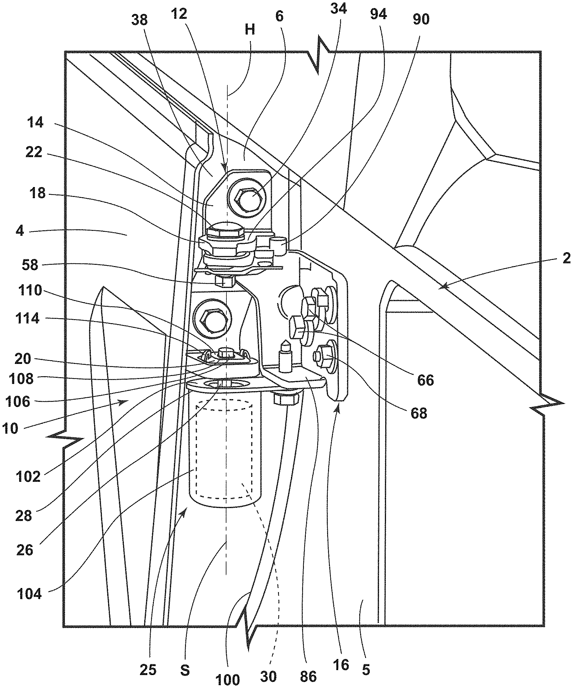
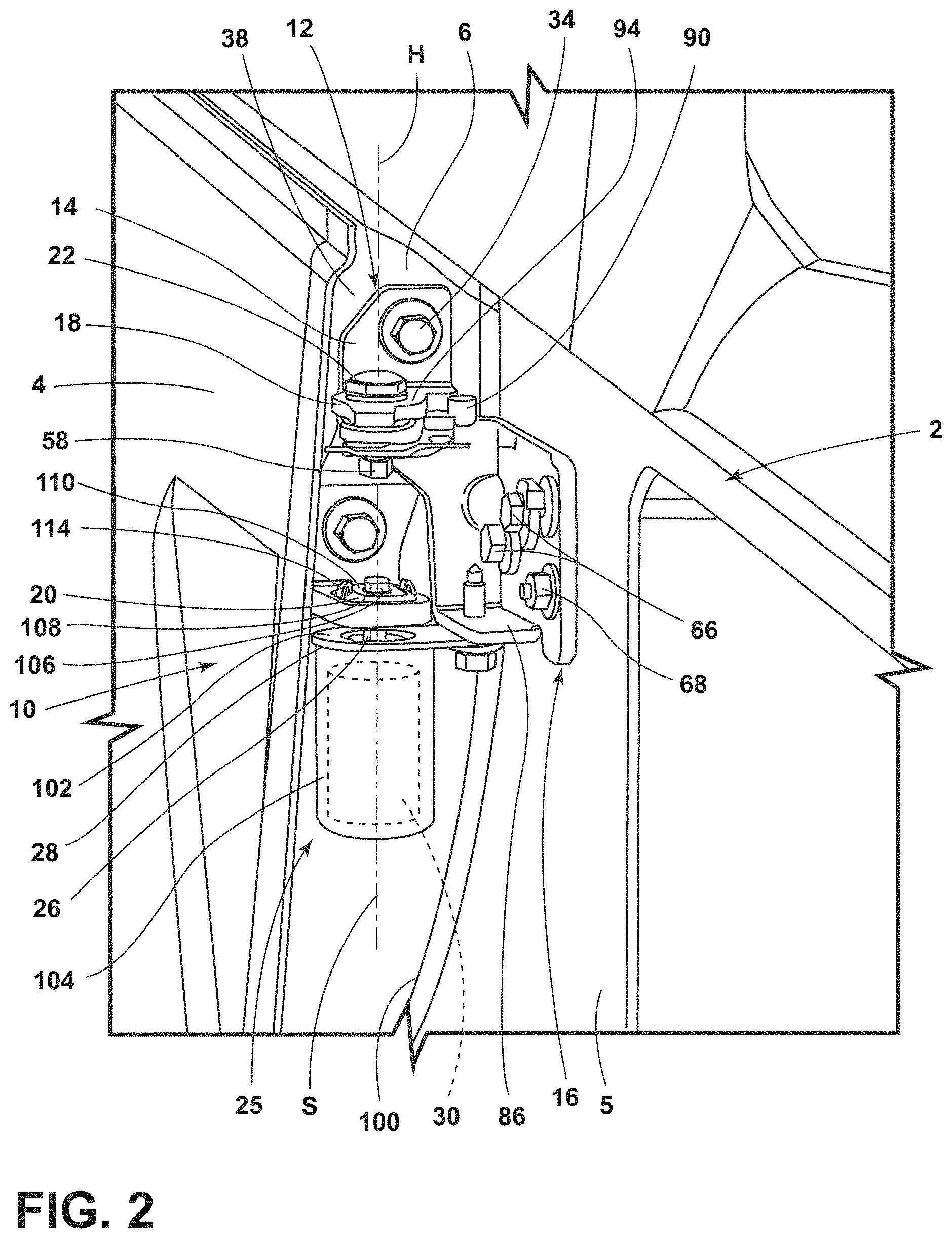
[0033] FIG. 2 is a partially fragmentary isometric view of an automated door system according to one aspect of the present disclosure;
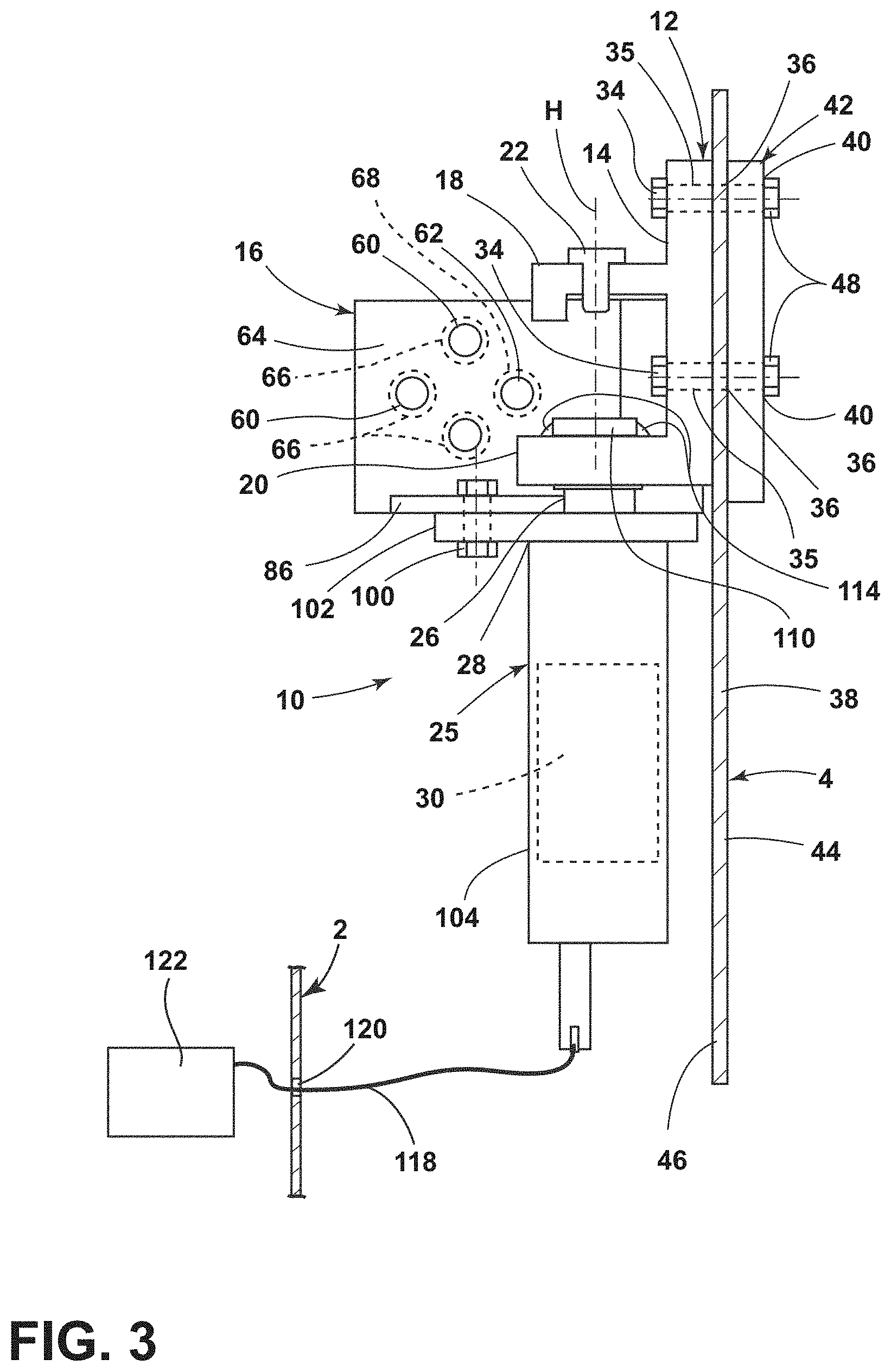
[0034] FIG. 3 is a partially schematic view of the door system of FIG. 2;
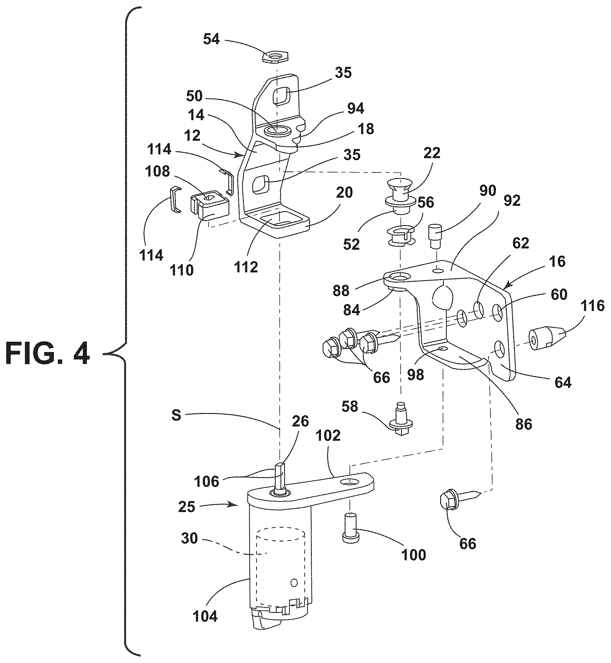
[0035] FIG. 4 is an exploded isometric view of the door assembly of FIG. 2; and
[0036] FIG. 5 is a partially fragmentary isometric view showing an optional through-bolt connector that integrates hinge attachment with an instrument panel compensator joint assembly.
DETAILED DESCRIPTION OF THE PREFERRED EMBODIMENTS
[0037] For purposes of description herein, the terms "upper," "lower," "right," "left," "rear," "front," "vertical," "horizontal," and derivatives thereof shall relate to the disclosure as oriented in FIG. 1. However, it is to be understood that the disclosure may assume various alternative orientations and step sequences, except where expressly specified to the contrary. It is also to be understood that the specific devices and processes illustrated in the attached drawings, and described in the following specification are simply exemplary embodiments of the inventive concepts defined in the appended claims. Hence, specific dimensions and other physical characteristics relating to the embodiments disclosed herein are not to be considered as limiting, unless the claims expressly state otherwise.
[0038] This patent application is related to U.S. Pat. No. 9,834,974, issued on Dec. 5, 2017, entitled "AUTOMOTIVE DOOR POWER ASSIST," and U.S. Pat. No. 10,301,863, issued on May 28, 2019, entitled "MOUNTING AND ALIGNING A VEHICLE SIDE DOOR MOTOR WITHIN THE CURRENT BILL OF PROCESS." The entire contents of each of these patents are incorporated herein by reference.
[0039] With reference to FIG. 1, a motor vehicle 1 includes a body 2 having one or more door openings 3 that can be selectively closed off by one or more doors 4. Body structure 2 may include an upright hinge pillar 5, and door 4 may be pivotally connected to the hinge pillar 5 of body structure 2 by one or more hinges such as lower hinge 8 and upper hinge 10 to provide for opening and closing movement of door 4 as shown by the arrow "A." In a preferred embodiment, the lower hinge 8 comprises a conventional (non-powered) hinge assembly, and upper hinge assembly 10 comprises a powered hinge assembly as described in more detail below. However, it will be understood that the lower hinge assembly 8 may comprise a powered hinge, and upper hinge assembly 10 may comprise a conventional (non-powered) hinge assembly. Alternatively, both hinge assemblies 8 and 10 may comprise powered hinge assemblies.
[0040] With further reference to FIGS. 2-4, hinge assembly 10 includes a movable hinge portion 12 having a base 14 as coupled to a forward panel or plate 6 of the door 4. The hinge assembly 10 further includes a fixed hinge portion 16 that is coupled to the vehicle body 2 at hinge pillar 5. The movable hinge portion 12 includes vertically spaced-apart upper and lower mounting portions 18 and 20, respectively. The upper mounting portion 14 is rotatably connected to the fixed hinge portion 16 via a hinge pin 22 or other suitable arrangement for rotation about a hinge axis H of the hinge assembly 10. Hinge axis H is preferably upright (e.g. vertical). However, it will be understood that the present disclosure is not limited to this configuration.
[0041] The hinge assembly 10 further includes a power assist device 25 coupled to the fixed hinge portion 16 and further coupled to the lower mounting portion 20 of the movable hinge portion 12 by a drive shaft 26 extending outwardly from an end 28 of the power assist device 25. The drive shaft 26 rotates about a shaft "S" that is preferably coaxial with the hinge axis H. A motor 30 is disposed within the power assist device 25 and configured to drive (rotate) the drive shaft 26 for providing at least one of opening and closing movement of the door 4 about the hinge axis H of the hinge assembly 10. Motor 30 is preferably an electric motor that can rotate drive shaft 26 in opposite rotational directions, and selectively fix drive shaft 26 at a selected rotational position to thereby retain door 4 at a selected open or partially open position. However, motor 30 may optionally comprise one or more of a power winch, an actuator, a servo motor, an electric solenoid, a pneumatic cylinder, and a hydraulic cylinder.
[0042] The hinge assembly 10 and door 4 of the present disclosure may be configured to operate in substantially the same manner as the power assist of U.S. Pat. No. 9,834,974. For example, the hinge assembly 10 may be configured to slow movement of the door 4 along a door swing path from an initial velocity to a slow close velocity when the initial velocity exceeds a predetermined threshold velocity, thereby providing a slow and controlled close when a user attempts to slam the door 4. The hinge assembly 10 may further be configured to provide for powered opening and/or closing movement of the door as initiated by a user. In particular, the hinge assembly 10 may be configured to operate as discussed in connection with FIGS. 8-11 of U.S. Pat. No. 9,834,974. However, it will be understood that the operation of the hinge assembly 10 of the present disclosure is not necessarily limited to the operation of the automotive door power assist of U.S. Pat. No. 9,834,974.
[0043] Referring again to FIGS. 2-4, the base 14 of movable hinge portion 12 may include a plurality of openings 35 that receive threaded fasteners 34. Threaded fasteners 34 may comprise bolts that extend through openings 36 in door panel 38 (FIG. 3), and through openings 40 in a mounting plate 42 that is disposed on an inner side 44 of door panel 38 opposite an outer side 46 of door panel 38. Threaded nuts 48 or the like engage threaded fasteners 34 to thereby secure the movable hinge portion 12 to the door panel 38. Movable hinge portion 12 includes upper and lower mounting portions 18 and 20, respectively, that extend transversely from the base 14 of the movable hinge portion 12 (FIG. 4). Movable hinge portion 12 may comprise virtually any suitable material. In a preferred embodiment, movable hinge portion 12 comprises an integral one-piece forged steel structure.
[0044] The fixed hinge portion 16 includes a fixed base portion 64 that may be in the form of a generally upright web having a plurality of openings 60 therethrough that receive bolts 66 to secure the fixed hinge portion 16 to the hinge pillar 5. An optional alignment pin 116 may be received in an opening (not shown) in body structure 2 to align and position fixed image portion 16 relative to body structure 2. As discussed in more detail below, the fixed base portion 64 may optionally include an opening 62 that is configured to receive an elongated instrument panel ("IP") bolt 68 (FIG. 5).
[0045] Referring again to FIGS. 2-4, the fixed hinge portion 16 may include upper and lower connecting portions 84 and 86, respectively, that extend transversely from the fixed base portion 64. When the hinge assembly 10 is assembled, pivot 22, pivot washer 54, bushing 56, and pivot bolt 58 engage opening 50 in movable hinge portion 12 and opening 88 in fixed hinge portion 16 to thereby pivotally interconnect the movable hinge portion 12 and fixed hinge portion 16. The upper mounting portion 18 of movable hinge portion 12 is positioned above upper connecting portion 84 of fixed hinge portion 16 such that the weight of door 4 tends to cause the movable hinge portion 12 to push downwardly on upper connecting portion 84 of the fixed hinge portion 16. A stop pin 90 may be received in an opening 92 of fixed hinge portion 16. The stop pin 90 is configured to engage edge 94 of upper mounting portion 18 (see also FIG. 2) to thereby provide detents and/or limit travel of door 4 in an opening direction in a known manner.
[0046] The lower connecting portion 86 (FIG. 4) of fixed hinge portion 16 includes an opening 98 that receives a bolt 100 (see also FIG. 2). Bolt 100 secures a plate 102 of power assist device 25 to the fixed hinge portion 16. In particular, the plate 102 is rigidly fixed to upper end 28 of housing 104 of power assist device 25, and the bolt 100 therefore rigidly secures the housing 104 to the fixed hinge portion 16. It will be understood that some rotation of plate 102 about bolt 100 may be possible prior to tightening of bolt 100 (e.g., to provide adjustment during assembly). However, because bolt 100 is offset from axis S of drive shaft 26, bolt 100 prevents rotation of housing 104 of power assist device 25. End portion 106 (FIG. 4) of drive shaft 26 may have a non-circular cross sectional shape (e.g. cylindrical with flat surface 106 on opposite sides) that engages a corresponding non-circular opening 108 in a connector 110 such that the connector 110 is rotationally fixed relative to shaft 106 and rotates with shaft 106 and thereby transfers torque from shaft 26 to connector 110. The connector 110 may be received in a square or rectangular cavity or opening 112 (FIG. 4) of lower mounting portion 20 of movable hinge portion 12 such that connector 110 is rotationally fixed to hinge portion 12. Thus, drive shaft 26 of motor 30 is rotationally fixed to movable hinge portion 12. Clips 114 secure the connector 110 to the lower mounting portion 20 and drive shaft 26. Because housing 104 of power assist device 25 is secured to fixed hinge portion 16 and body 2, actuation of motor 30 causes shaft 26 to rotate relative to housing 104, and rotation of shaft 26 causes movable hinge portion 12 and door 4 to rotate about hinge axis H relative to body 2.
[0047] With reference to FIG. 5, IP bolt 68 extends through a compression tube 70 and through openings 74A and 74B in opposite sidewalls 72A and 72B, respectively, of hinge pillar 5. The elongated IP bolt 68 has an inner end 76 that engages an instrument panel compensator joint 78. The elongated IP bolt 68 and instrument panel compensator joint 78 may be substantially similar to existing instrument panel components. These components interconnect the instrument panel components and cross beam structure 80 in a known manner. Although the elongated IP bolt 68 and instrument panel compensator joint 78 may be substantially similar to known components, the outer end 82 of IP bolt 68 bears against the fixed base portion 64 of fixed hinge portion 16 to thereby simultaneously clamp/support the instrument panel components and secure the fixed hinge portion 16 to the hinge pillar 5.
[0048] Referring again to FIG. 3, a plurality of electrical lines 118 may operably interconnect the power assist device 25 to a vehicle power and control system 122. The electrical lines 118 may extend through an opening 120 of vehicle body 2. The opening 120 may be sealed by grommets or other suitable pass-through feature (not shown). Because the power assist device 25 is secured to the fixed hinge portion 16 which is secured to the vehicle body 2, the power assist device 25 does not move relative to the vehicle body 2, and the electrical lines 118 do not move as door 4 opens and closes. However, electrical lines 118 may alternatively be routed through an opening in door panel 38. It will be understood that the vehicle power and control system 122 may include one or more control units or modules that are operably interconnected by one or more onboard networks in virtually any configuration as required for a particular application.
[0049] It is to be understood that variations and modifications can be made on the aforementioned structure without departing from the concepts of the present disclosure, and further it is to be understood that such concepts are intended to be covered by the following claims unless these claims by their language expressly state otherwise.
* * * * *
D00000
D00001
D00002
D00003
D00004
D00005
XML
uspto.report is an independent third-party trademark research tool that is not affiliated, endorsed, or sponsored by the United States Patent and Trademark Office (USPTO) or any other governmental organization. The information provided by uspto.report is based on publicly available data at the time of writing and is intended for informational purposes only.
While we strive to provide accurate and up-to-date information, we do not guarantee the accuracy, completeness, reliability, or suitability of the information displayed on this site. The use of this site is at your own risk. Any reliance you place on such information is therefore strictly at your own risk.
All official trademark data, including owner information, should be verified by visiting the official USPTO website at www.uspto.gov. This site is not intended to replace professional legal advice and should not be used as a substitute for consulting with a legal professional who is knowledgeable about trademark law.