Tire Disabling Device
Novak; Louis ; et al.
U.S. patent application number 17/008604 was filed with the patent office on 2021-03-04 for tire disabling device. The applicant listed for this patent is Novak IP Holdings LLC. Invention is credited to Frank Novak, Louis Novak.
| Application Number | 20210062443 17/008604 |
| Document ID | / |
| Family ID | 1000005086421 |
| Filed Date | 2021-03-04 |


| United States Patent Application | 20210062443 |
| Kind Code | A1 |
| Novak; Louis ; et al. | March 4, 2021 |
TIRE DISABLING DEVICE
Abstract
Disclosed herein is a tire disabling device. A tire disabling device may comprise a spike-bearing plate that may be contained, in its undeployed state, in a handled enclosure. Upon deployment, the spike bearing plate may be disposed under the tire of a stopped vehicle, which may puncture the tire if the vehicle is moved. Such a device may be beneficial in preventing car chases that begin with traffic stops, by deflating tires upon an attempted evasion from the stop, and by signaling a deterrent to attempt such evasion.
| Inventors: | Novak; Louis; (Twinsburg, KY) ; Novak; Frank; (Twinsburg, OH) | ||||||||||
| Applicant: |
|
||||||||||
|---|---|---|---|---|---|---|---|---|---|---|---|
| Family ID: | 1000005086421 | ||||||||||
| Appl. No.: | 17/008604 | ||||||||||
| Filed: | August 31, 2020 |
Related U.S. Patent Documents
| Application Number | Filing Date | Patent Number | ||
|---|---|---|---|---|
| 62893230 | Aug 29, 2019 | |||
| Current U.S. Class: | 1/1 |
| Current CPC Class: | E01F 13/12 20130101 |
| International Class: | E01F 13/12 20060101 E01F013/12 |
Claims
1. A tire disabling device comprising: an enclosure having an opening to an interior cavity; a handle attached to the enclosure; a spike plate comprising at least one of: at least one integrated spike, and at least one spike configuration feature; at least one spike, wherein the at least one spike comprises at least one of: the at least one integrated spike, and a spike interfaced with the at least one spike configuration feature; a coupling mechanism, disposed near the top of the enclosure, configured to interface with a distal end of the spike plate so as to detachably secure the spike plate in place; and a pivot mechanism, disposed near the bottom of the enclosure, configured to pivotably couple with a proximal end of the spike plate so as to permit the spike plate to pivot from a secure configuration, wherein the distal end of the spike plate is proximate to the coupling mechanism and the at least one spike is enclosed within the enclosure, and a deployed configuration, wherein the distal end of the spike plate is substantially in contact with a ground surface.
2. The tire disabling device of claim 1, wherein the handle is retractable.
3. The tire disabling device of claim 1, further comprising a safety mechanism configured to prevent the handle from completely detaching from the tire disabling device in the event of an interaction between the tire disabling device and a vehicle tire.
4. The tire disabling device of claim 3, wherein the safety mechanism comprises a spring-loaded retractor, a handle connector, and a cord, wherein the cord is connected at one end to the spring-loaded retractor and at the other end to the handle connector, further wherein the handle connector is fixed to the handle.
5. The tire disabling device of claim 1, wherein the spike plate further comprises a tab.
6. The tire disabling device of claim 1, wherein the coupling mechanism comprises a magnet.
7. The tire disabling device of claim 1, wherein the coupling mechanism comprises at least one of: a clasp, a notch, a tab, a spring, a hinge, and a pin.
8. The tire disabling device of claim 1, further comprising a base plate disposed on a bottom surface of the enclosure.
9. The tire disabling device of claim 8, wherein the base plate further comprises at least one of: a wheel, a ball, a glider, and a friction-reducing element.
10. The tire disabling device of claim 1, further comprising an alerting feature comprising at least one of a reflector, a light, a sound-emitting device, and a wireless communication element.
11. The tire disabling device of claim 1, further comprising a countermeasure comprising at least one of: netting, expanding elements, releasable substances, and a car electronics disruptor.
12. A storage apparatus for storing a tire disabling device, the storage apparatus comprising: an enclosure comprising an interior cavity and plurality of retention plates, the plurality of retention plates disposed in an orientation substantially perpendicular to a surface of the enclosure so as to form the interior cavity, configured to permit the ingress of the tire disabling device into the interior cavity; at least one strap disposed on the enclosure, configured to releasably secure the tire disabling device, wherein the plurality of retention plates together with the at least one strap are configured to secure the tire disabling device within the interior cavity and substantially prevent the egress of the tire disabling device from the storage apparatus.
13. The storage apparatus of claim 12, wherein the plurality of retention plates comprises a top plate, a bottom plate, and four side plates, further wherein the at least one strap comprises lengths of webbing material terminated with side-release buckles, further wherein the at least one strap is configured to releasably secure the tire disabling device by encircling the tire disabling device and engaging the side-release buckles.
14. A method of utilizing a tire disabling device, the method comprising: placing the tire disabling device in the proximity of a stopped vehicle; deploying a spike plate, the spike plate comprising one or more spikes, each of the one or more spikes comprising a puncturing element, wherein deploying the spike plate exposes the puncturing element of at least one of the one or more spikes; and disposing the spike plate in front of and below at least part of a tire of the stopped vehicle, such that the puncturing element of at least one of the one or more spikes is positioned to puncture the tire upon the traversal of the tire over the spike plate.
15. The method of claim 14, further comprising an initial stage of removing the tire disabling device from a storage apparatus.
16. The method of claim 14, wherein placing the disabling device in the proximity of the stopped vehicle further comprises rolling the device along the ground on at least one of: a wheel, a ball, a glider, and a friction-reducing element.
17. The method of claim 14, wherein at least one of placing the disabling device in the proximity of the stopped vehicle, deploying the spike plate, and disposing the spike plate in front of and below at least part of the tire of the stopped vehicle further comprises the activation of an alerting feature comprising at least one of a light, a sound-emitting device, and a wireless communication element.
18. The method of claim 14, further comprising a final stage wherein the tire traverses the spike plate, puncturing the tire by the puncturing element of at least one of the one or more spikes.
19. The method of claim 18, wherein the final stage further comprises the deployment of at least one of: netting, expanding elements, releasable substances, and a car electronics disruptor.
20. The method of claim 18, wherein a safety mechanism configured to prevent a handle of the tire disabling device from completely detaching from the tire disabling device in the event of an interaction between the tire disabling device and a vehicle tire prevents the handle from completely detaching from the tire disabling device.
Description
RELATED APPLICATION
[0001] Under the provisions of 35 U.S.C. .sctn. 119(e), the Applicant claims the benefit of U.S. Provisional Patent Application No. 62/893,230, filed Aug. 29, 2019, which is incorporated herein by reference.
FIELD OF DISCLOSURE
[0002] The present disclosure relates to a device for deflating vehicle tires. More specifically, the present disclosure relates to a device that may be disposed under a tire of a stopped vehicle in order to deflate the deflate the tire should the vehicle be moved, acting as a deterrent to such movement.
BACKGROUND
[0003] A car chase can be extremely dangerous to law enforcement officers (LEOs), other motorists, bystanders, and the chased driver. Although some car chases result from a refusal of a vehicle to pull over as directed, other car chases begin from a traffic stop. A vehicle peeling out from a traffic stop, and subsequently driving away (usually at high speeds), poses the risk of serious injury or death in a wide surrounding area.
[0004] Traditional approaches to dealing with car chases include active maneuvers by law enforcement vehicles such as ramming, boxing in, or the Pursuit Intervention Technique (PIT), which aims to strike and spin the fleeing vehicle, as well as more passive containment techniques such as laying down spike strips in the anticipated path of the fleeing vehicle (to deflate the tires and slow the vehicle), deploying netting or devices that disrupt car electronics, or blocking the road with barriers or police vehicles. In rare cases of extreme danger, LEOs may shoot out a fleeing vehicle's tires or fire at a rapidly approaching vehicle.
[0005] The challenges of stopping a car chase after it has already started lead to inevitable shortcomings. While these approaches are often ultimately effective, they may only be so following significant prior property damage and casualty. They afford the fleeing motorist a chance to get away, especially as the driver is inherently in an advantageous position to begin their flight over an officer who is out of their vehicle. Many of these techniques also necessarily put LEOs in the path of harm's way in order to deploy them.
[0006] Further, the employment of some of these techniques, while perhaps preferable to failing to stop the fleeing motorist, may themselves introduce danger at high rates of speed. Permitting a chase to begin from a stop and escalate to high speed greatly increases the potential for a vehicle subject to a countermeasure such as a spike strip to roll, flip, careen, or otherwise become a deadly, uncontrollable projectile. Contrarywise, a countermeasure that was able to deflate vehicle tires from a stop may assist in preventing a chase from ever reaching high speeds. And a motorist who is aware of such countermeasures, in place at a traffic stop, may disincentivize the motorist from the temptation to speed off in the first place.
[0007] A device that could be employed with respect to a stopped vehicle that could effectively prevent, mitigate, or deter an ensuing speed-off and car chase may therefore provide advantages over the traditional approaches.
[0008] In view of at least the above shortcomings, a need exists for a tire disabling device.
BRIEF OVERVIEW
[0009] This brief overview is provided to introduce a selection of concepts in a simplified form that are further described below in the Detailed Description. This brief overview is not intended to identify key features or essential features of the claimed subject matter. Nor is this brief overview intended to be used to limit the claimed subject matter's scope.
[0010] A tire disabling device (or "device") may be provided.
[0011] One objective of the disclosed tire disabling device may be to provide a portable device comprising a spike plate that can be deployed and positioned under a vehicle tire in order to puncture the tire if the vehicle is moved.
[0012] Another objective of the disclosed tire disabling device may be to decrease the incidence of car chases from traffic stops by deterring drivers from fleeing.
[0013] Yet another objective of the disclosed tire disabling device may be to provide a variety of storage configurations whereby a tire disabling device can be mounted and accessibly stored in the interior, trunk, or exterior of a vehicle.
[0014] Still another objective of the disclosed tire disabling device may be to provide a handle for ease of positioning and carrying, wherein the handle may or may not be retractable.
[0015] Again, another objective of the disclosed tire disabling device may be to provide a base plate for stabilizing the device, wherein the base plate may or may not comprise wheels or friction reducing elements.
[0016] Further, an objective of the disclosed tire disabling device may be to provide alerting features such as reflectors, reflective paint, lighting elements (e.g., LED, HID, strobing, flashing, pulsing, rotating, color changing, etc.), auditory elements, horns, sirens, whistles, or wireless communication elements, any of which may serve to alert the LEO and/or the driver as to the continued presence of the deployed device (especially with respect to a concluded traffic stop).
[0017] Further, another objective of the disclosed tire disabling device may be to provide a safety mechanism to secure a handle of the device from becoming completely detached from the device in the event of a rollover and puncture, which may prevent the handle from becoming a dangerous projectile.
[0018] Further, yet another objective of the disclosed tire disabling device may be to provide a cavity within which the spikes of a spike plate are protectively enclosed.
[0019] Further, still another objective of the disclosed tire disabling device may be to provide a retention and release mechanism for the spike plate, which may comprise magnets, clasps, notches, tabs, springs, hinges, pins, and other means of releasably securing the spike plate to the device.
[0020] Further, again another objective of the disclosed tire disabling device may be to allow a user to deploy the spike plate by gravity, by jolt of a retractable handle being extended to its maximum, or by pushing a tab.
[0021] Even further, an objective of the disclosed tire disabling device may be to incorporate evasion countermeasures in addition to a spike plate, such as netting, car electronics disruptors, releasable substances, or expanding elements.
[0022] Both the foregoing brief overview and the following detailed description provide examples and are explanatory only. Accordingly, the foregoing brief overview and the following detailed description should not be considered to be restrictive. Further, features or variations may be provided in addition to those set forth herein. For example, embodiments may be directed to various feature combinations and sub-combinations described in the detailed description.
BRIEF DESCRIPTION OF THE DRAWINGS
[0023] The accompanying drawings, which are incorporated in and constitute a part of this disclosure, illustrate various embodiments of the present disclosure. The drawings contain representations of various trademarks and copyrights owned by the Applicants. In addition, the drawings may contain other marks owned by third parties and are being used for illustrative purposes only. All rights to various trademarks and copyrights represented herein, except those belonging to their respective owners, are vested in and the property of the Applicants. The Applicants retain and reserve all rights in their trademarks and copyrights included herein, and grant permission to reproduce the material only in connection with reproduction of the granted patent and for no other purpose.
[0024] Furthermore, the drawings and their brief descriptions below may contain text or captions that may explain certain embodiments of the present disclosure. This text is included for illustrative, non-limiting, explanatory purposes of certain embodiments detailed in the present disclosure. In the drawings:
[0025] FIG. 1A illustrates a perspective view of a tire disabling device in accordance with various embodiments of the present disclosure.
[0026] FIG. 1B illustrates an exploded view of a tire disabling device in accordance with various embodiments of the present disclosure.
[0027] FIG. 2 illustrates a side elevation view of a storage apparatus for a tire disabling device in accordance with various embodiments of the present disclosure.
[0028] FIG. 3A illustrates a front-facing side elevation view of a storage apparatus for a tire disabling device in accordance with various embodiments of the present disclosure.
[0029] FIG. 3B illustrates a side-facing side elevation view of a storage apparatus for a tire disabling device in accordance with various embodiments of the present disclosure.
[0030] FIG. 3C illustrates a top plan view of a storage apparatus for a tire disabling device in accordance with various embodiments of the present disclosure.
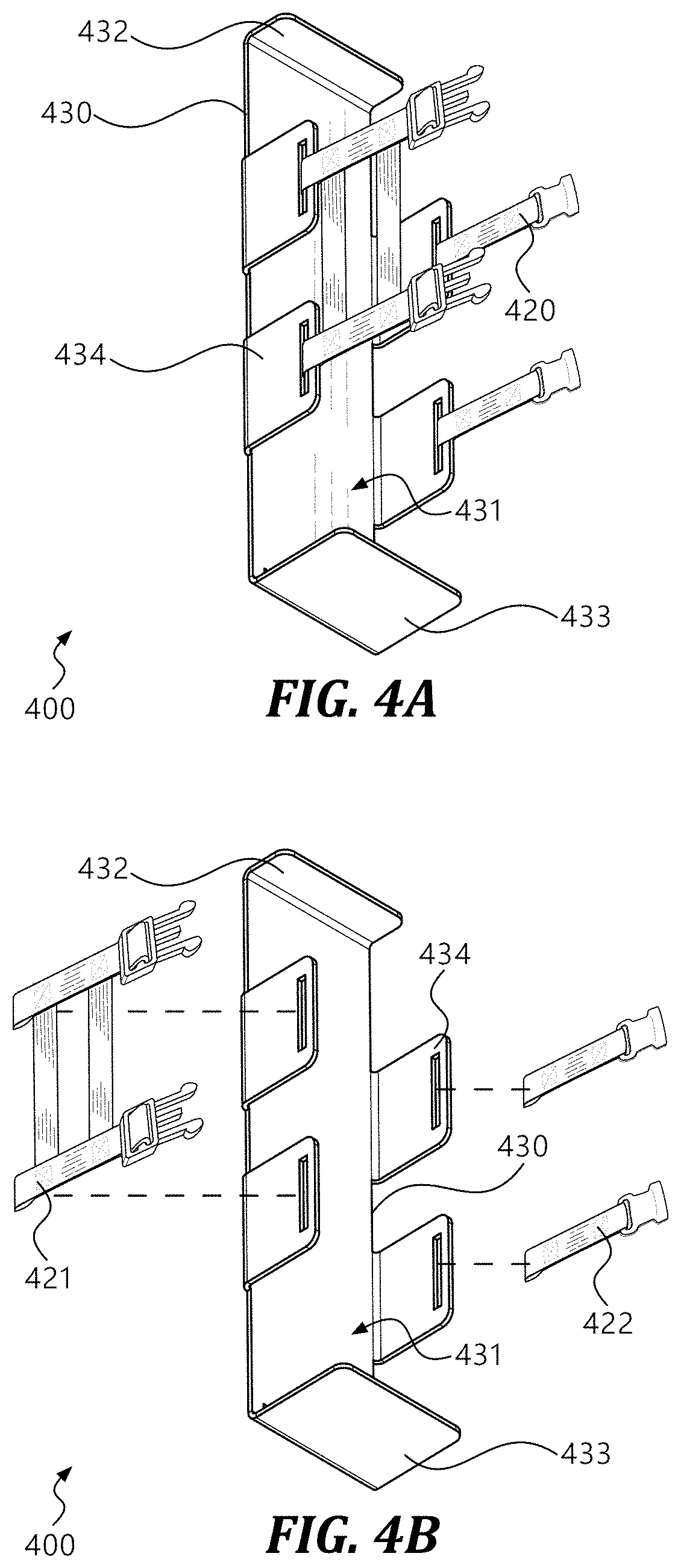
[0031] FIG. 4A illustrates a perspective view of a storage apparatus for a tire disabling device in accordance with various embodiments of the present disclosure.
[0032] FIG. 4B illustrates an exploded view of a storage apparatus for a tire disabling device in accordance with various embodiments of the present disclosure.
[0033] FIG. 5 illustrates a flow diagram of an example method of utilizing a tire disabling device in accordance with various embodiments of the present disclosure.
DETAILED DESCRIPTION
[0034] As a preliminary matter, it will readily be understood by one having ordinary skill in the relevant art that the present disclosure has broad utility and application. As should be understood, any embodiment may incorporate only one or a plurality of the above-disclosed aspects of the disclosure and may further incorporate only one or a plurality of the above-disclosed features. Furthermore, any embodiment discussed and identified as being "preferred" is considered to be part of a best mode contemplated for carrying out the embodiments of the present disclosure. Other embodiments also may be discussed for additional illustrative purposes in providing a full and enabling disclosure. Moreover, many embodiments, such as adaptations, variations, modifications, and equivalent arrangements, will be implicitly disclosed by the embodiments described herein and fall within the scope of the present disclosure.
[0035] Accordingly, while embodiments are described herein in detail in relation to one or more embodiments, it is to be understood that this disclosure is illustrative and exemplary of the present disclosure and are made merely for the purposes of providing a full and enabling disclosure. The detailed disclosure herein of one or more embodiments is not intended, nor is to be construed, to limit the scope of patent protection afforded in any claim of a patent issuing here from, which scope is to be defined by the claims and the equivalents thereof. It is not intended that the scope of patent protection be defined by reading into any claim a limitation found herein that does not explicitly appear in the claim itself.
[0036] Thus, for example, any sequence(s) and/or temporal order of stages of various processes or methods that are described herein are illustrative and not restrictive. Accordingly, it should be understood that, although stages of various processes or methods may be shown and described as being in a sequence or temporal order, the stages of any such processes or methods are not limited to being carried out in any particular sequence or order, absent an indication otherwise. Indeed, the stages in such processes or methods generally may be carried out in various different sequences and orders while still falling within the scope of the present disclosure. Accordingly, it is intended that the scope of patent protection is to be defined by the issued claim(s) rather than the description set forth herein.
[0037] Additionally, it is important to note that each term used herein refers to that which an ordinary artisan would understand such term to mean based on the contextual use of such term herein. To the extent that the meaning of a term used herein--as understood by the ordinary artisan based on the contextual use of such term--differs in any way from any particular dictionary definition of such term, it is intended that the meaning of the term as understood by the ordinary artisan should prevail.
[0038] Regarding applicability of 35 U.S.C. .sctn. 112, 6, no claim element is intended to be read in accordance with this statutory provision unless the explicit phrase "means for" or "stage for" is actually used in such claim element, whereupon this statutory provision is intended to apply in the interpretation of such claim element.
[0039] Furthermore, it is important to note that, as used herein, "a" and "an" each generally denotes "at least one," but does not exclude a plurality unless the contextual use dictates otherwise. When used herein to join a list of items, "or" denotes "at least one of the items," but does not exclude a plurality of items of the list. Finally, when used herein to join a list of items, "and" denotes "all of the items of the list."
[0040] The following detailed description refers to the accompanying drawings. Wherever possible, the same reference numbers are used in the drawings and the following description to refer to the same or similar elements. While many embodiments of the disclosure may be described, modifications, adaptations, and other implementations are possible. For example, substitutions, additions, or modifications may be made to the elements illustrated in the drawings, and the methods described herein may be modified by substituting, reordering, or adding stages to the disclosed methods. Accordingly, the following detailed description does not limit the disclosure. Instead, the proper scope of the disclosure is defined by the appended claims. The present disclosure contains headers. It should be understood that these headers are used as references and are not to be construed as limiting upon the subjected matter disclosed under the header.
[0041] The present disclosure includes many aspects and features. Moreover, while many aspects and features relate to, and are described in, the context of, embodiments of the present disclosure are not limited to use only in this context.
I. OVERVIEW
[0042] Consistent with embodiments of the present disclosure, a tire disabling device (or simply "device") 100 is provided. Various embodiments of device 100 are described herein. Components of device 100 as presented in the following disclosure may be integrated, used independently, in conjunction with, used separately, or in connection with other embodiments they are not shown or described as functioning with. Any aspects of one embodiment may or may not be used interchangeably with other elements and aspects of a device 100 as presented in the present disclosure.
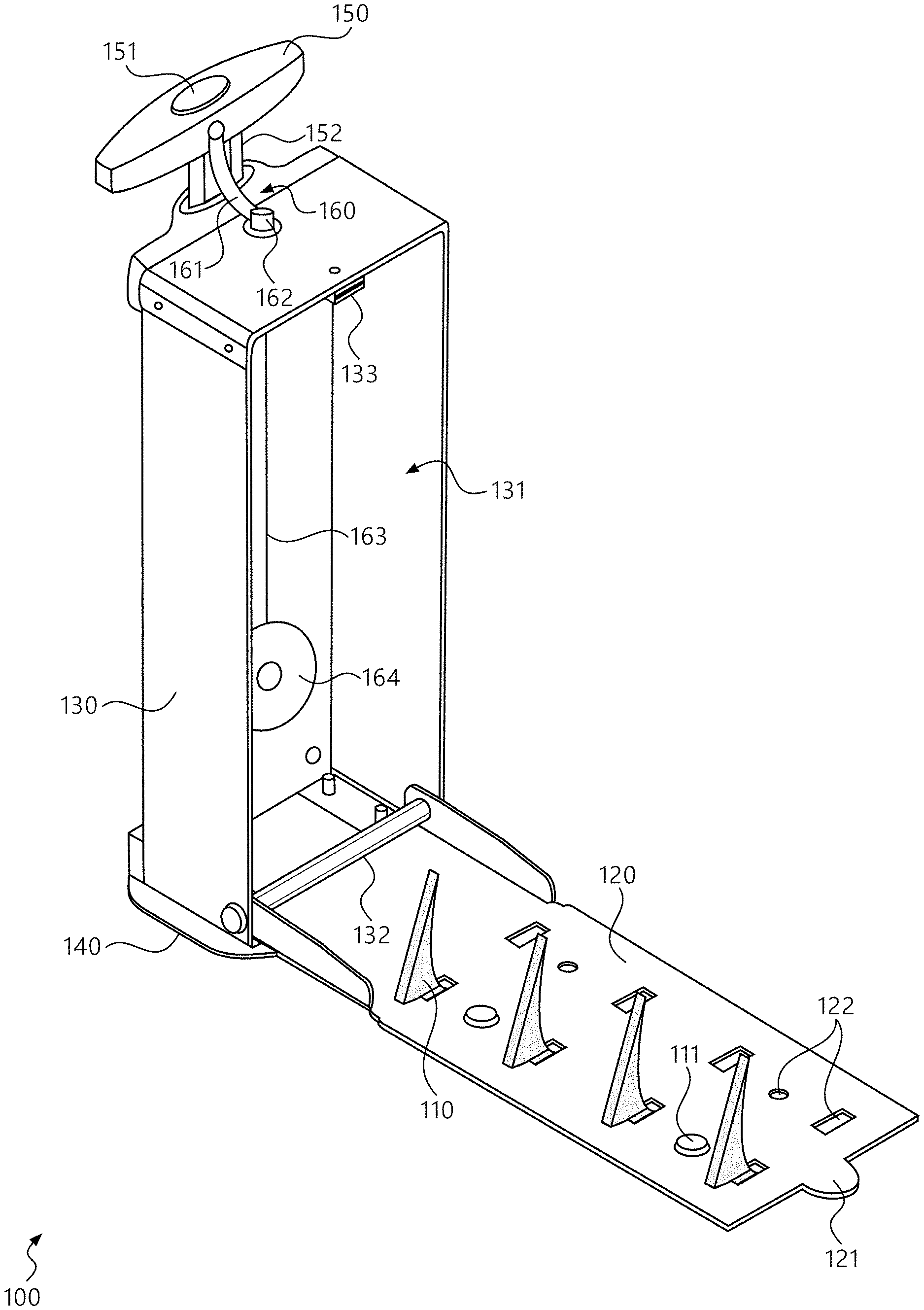
[0043] Referring now to FIGS. 1A-B, there is shown an example tire disabling device 100 consistent with various embodiments of the present disclosure. Device 100 may comprise an enclosure 130 which may have a handle 150, a base plate 140, and a spike plate 120 which may be equipped (or integral) with spikes 110. Device 100 may also comprise a safety mechanism 160, which may assist in keeping handle 150 from becoming separated from the rest of device 100 and a dangerous projectile in certain scenarios.
[0044] In various embodiments, device 100 may be used to puncture a tire of a vehicle when it rolls over spike plate 120, due to the spikes' 110 impingement into the tire. With spike plate 120 deployed (e.g., by a LEO), and device 100 in place under and in front of a vehicle tire, a motorist who would attempt to flee from a traffic stop may puncture their tire before getting up to speed, right at the scene of the stop they are attempting to flee. Device 100 may also, merely by its presence, deter such flight by the threat of puncture (and thus reduced viability of flight).
II. COMPONENTS
[0045] Some or all of the following components may be present in a tire disabling device 100. The below description is in no way intended to limit the components that may be present in addition or in alternative to the listed components, nor to require that any particular component be included in a form described below or at all.
[0046] a. Spike 110
[0047] Device 100 may comprise one or more spikes 110. Spikes 110 may provide the functionality of puncturing a tire that traverses spike plate 120. Spikes 110 may have various form factors, including as depicted in FIG. 1A, and/or other types of caltrops, arrows, barbs, pins, blades, and so forth. In some embodiments, spike 110 may be attached to a spike plate 120 comprising spike configuration features 122 via a spike retainer 111. Spike retainer 111 may comprise various securing components such as clevis pins, bridge pins, cotter pins, bolts, etc. Spikes 110 may, in some embodiments, be made of a stainless steel material.
[0048] b. Spike Plate 120
[0049] Device 100 may comprise a spike plate (or "plate") 120. Spike plate 120 may, in various embodiments, comprise a tab 121, spike configuration features 122, spikes 110 that are integral (not depicted in FIG. 1A) or modular (as depicted in FIG. 1A), and various other features. In embodiments comprising spike configuration features 122, it may be possible to install, remove, reverse, replace, etc. spikes 110 to account for factors like wear and tear and departmental policy regarding side of approach for traffic stops.
[0050] In some embodiments, plate 120 may attach to, and pivot about hinge 132. In an embodiment, device 100 may have two configurations with respect to plate 120. "Secured" configuration would have plate 120 is in an upright position (as depicted in FIG. 1A, tab 121 proximal to magnet 133) and a coupling mechanism (e.g., magnet 133) is securing plate 120 in place. "Deployed" configuration would have plate 120 against the ground, spikes 110 up.
[0051] In some embodiments, deploying spike plate 120 may involve "gravity deployment," e.g., jolting free plate 120 from magnet 133 via tapping device 100 on the ground or extending handle 150 to its maximum (in embodiments comprising a retractable handle 150), or by pushing tab 121 to free plate 120 from magnet 133. In some embodiments, various clasp, hook, pin, latch, etc. components may be utilized as the coupling mechanism between plate 120 and the upper part of enclosure 130.
[0052] c. Enclosure 130
[0053] Device 100 may comprise an enclosure (or "box") 130. Enclosure 130 may comprise an inner cavity 131 that may, in various embodiments, enclose spikes 110 while spike plate 120 is secured to the device 100 (the "secured" configuration). Cavity 131 may house elements of safety mechanism 160 and magnet 133. Enclosure 130 may be painted in reflective paint, covered in (or fabricated to have) reflective surface material, and comprise alerting features such as lights and sound-emitting features.
[0054] d. Base Plate 140
[0055] Device 100 may comprise a base plate (or "base") 140. Base plate 140 may provide a bottom surface that helps stabilize device 100, including an additional, low lying, source of mass that may help keep device 100 grounded. Base 140 may, in some embodiments, comprise one or more wheels, balls, gliders, or friction-reducing elements that may ease the movement and placement of device 100. Such embodiments may further comprise mechanisms for retracting or fixing the movement-assistive elements to prevent rolling, shifting, or sliding when device 100 is deployed and emplaced.
[0056] e. Handle 150
[0057] Device 100 may comprise a handle 150. Handle 150 may be used for carrying, positioning, and rolling (in embodiments featuring wheels) device 100. Handle 150 may be retractable; in an embodiment consistent therewith, a retractable handle 150 may have a release button 151 and telescoping arm 152.
[0058] Handle 150--along with other parts of device 100, such as box 130, but especially handle 150 due to its vertical prominence--may comprise or support alerting features such as reflectors, lights (e.g., spinning, strobing, pulsing, blinking, high luminosity) or auditory features (e.g., loudspeakers, sirens, horns). Among other benefits, these may help remind LEOs and motorists alike of the continued presence of a deployed device 100, the traversal of which after the benign conclusion of a traffic stop would have the same deleterious effect on the driver's tires as if the driver had been fleeing. Other alerting features such as wireless communications, in embodiments where they are present, may be housed in the handle 150 or elsewhere such as the enclosure 130.
[0059] f. Safety Mechanism 160
[0060] Device 100 may comprise a safety mechanism 160. Safety mechanism 160 may function to keep handle 150 from wholly separating from the rest of device 100 upon a puncturing event. In some such events, spikes 110 may travel circumferentially along with the rotation of the tire, bringing the spike plate 120 and the enclosure 130 and handle 150 attached thereto along this rotational path. As the device 100 rotates upside-down, it may bring an extended handle 150 into rapid and forceful contact with the ground. Safety mechanism 160 may prevent or mitigate the resulting breakaway of handle 150 and its unpredictable projectile trajectory.
[0061] In an embodiment, safety mechanism 160 may comprise a spring-loaded retractor (or "retractor") 164 attached to one end of a cord 163, the other end of which may be attached to a handle connector 161 (directly or intermediated by a stopper 162 in various embodiments). In an example of how safety mechanism 160 may operate in the above described context, handle 150 when fully extended would have a relatively longer extension of cord 163, under tension that would tend to pull back toward retractor 164. If handle 150 were to rapidly and forcefully contact the ground, so as to break off from device 100, the still-intact connection between retractor 164 and handle 150, via cord 163, may keep handle 150 from flying off dangerously.
[0062] g. Storage Apparatus 200
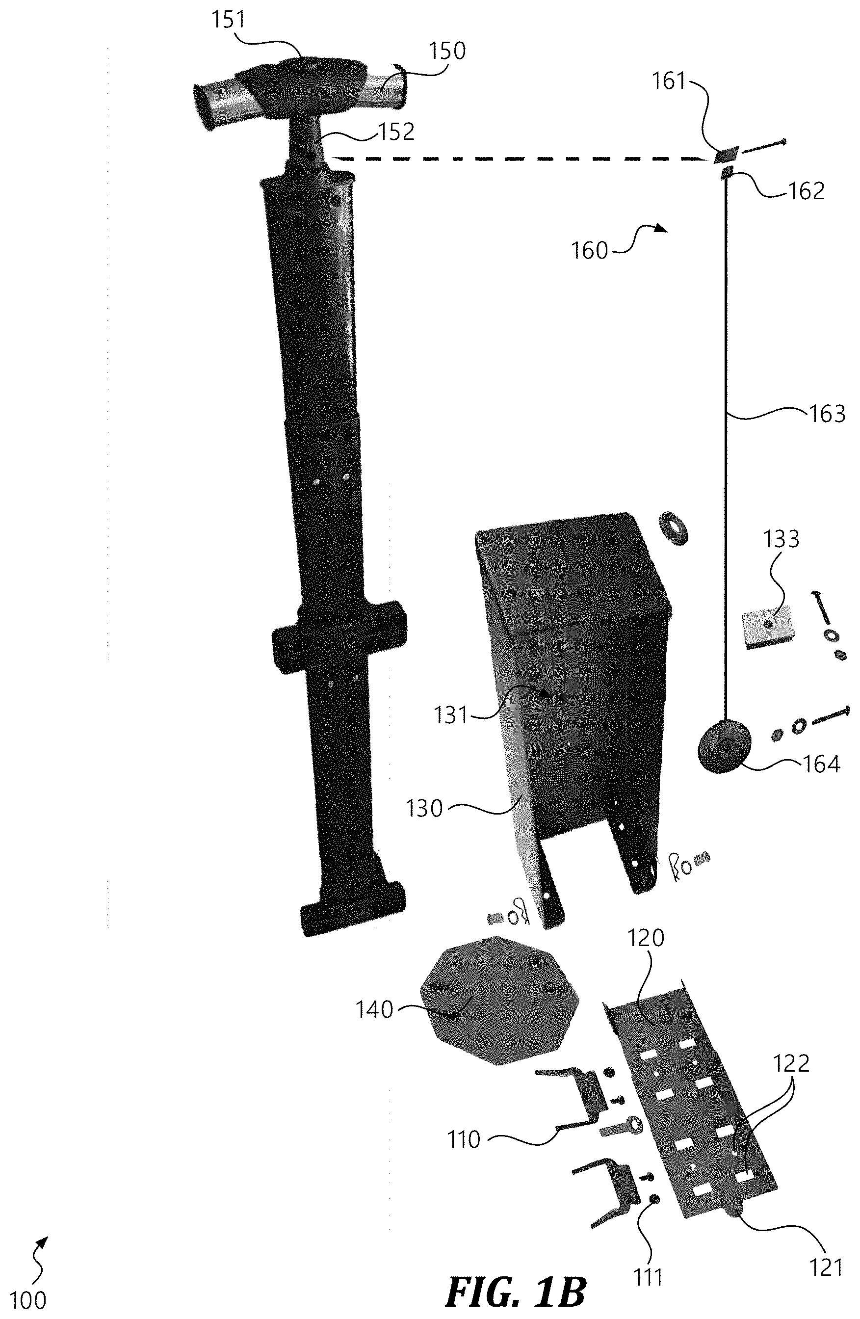
[0063] Referring now to FIG. 2, there is shown an example storage apparatus (or "SA") 200 consistent with various embodiments of the present disclosure. Device 100 may comprise, be compatible with, or be configured to be secured and transported in a storage apparatus 200. SA 200 may be configured to attach to the front or rear of a seat in a vehicle, and to transport device 100 therein. For example, SA 200 may be attached so as to hang over the front of the passenger seat in a LEO vehicle, providing easy access to device 100 upon making a traffic stop.
[0064] SA 200 may comprise a receptacle 210 in which device 100 may be stored. In some embodiments, receptacle 210 may comprise a firm-walled space that is wrapped in a nylon or canvas material. SA 200 may comprise a plurality of straps 220, which may be attached (e.g., sewn, glued, riveted) to receptacle 210 at attachment points 221. Straps 220 may incorporate coupling mechanisms including, in some embodiments, slide lock 222 and clip 223 configurations.
[0065] Receptacle 210 may comprise a door 240 that is dimensioned to permit ingress and egress of a device 100 from the interior cavity of receptacle 210. In some embodiments, door 240 may have a locking mechanism, such as bracket 241 and fasteners 242. Other methods of closure may include a variety of securing means, including magnets, hook and loop fasteners, and so forth. In some embodiments, door 240 may be situated as depicted in FIG. 2 (colloquially, "mailbox" style), whereas in other embodiments, door 240 may be on the front of SA 200, perpendicular to the depicted configuration (colloquially, "breadbox" style).
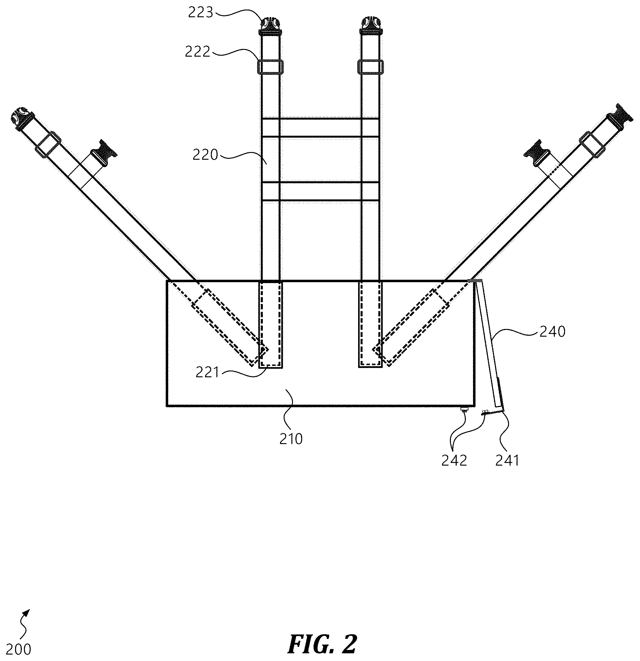
[0066] h. External Storage Apparatus 300
[0067] Referring now to FIGS. 3A-C, there is shown an example storage apparatus (or "SA") 300 consistent with various embodiments of the present disclosure. Device 100 may comprise, be compatible with, or be configured to be secured and transported in a storage apparatus 300. SA 300 may be configured to attach (via, e.g., fasteners 330) within a vehicle's trunk or to an exterior feature, and to transport device 100 therein. For example, SA 200 may be attached to the push bumper so as to have device 100 at the ready upon making a traffic stop.
[0068] SA 300 may comprise a back plate 310 against which device 100 may seat. In some embodiments, back plate 310 may comprise one or more slots, grooves, or locking features with which corresponding on device 100 may interface, securing device 100 against forward and sideways movement. SA 300 may further comprise a base plate 320, upon which device 100 may sit. In some embodiments, device 100 may be secured to base plate 320 by an electromagnet 321 thereunder, attached via screws 322, and the effect of which may be turned on or off by control unit 340.
[0069] Fasteners 330 may, but need not be, bolts or screws as depicted in FIGS. 3A-C. For example, fasteners 330 may comprise u-clamps or other clamping or securing mechanisms, as appropriate.
[0070] i. Storage Apparatus 400
[0071] Referring now to FIGS. 4A-B, there is shown an example storage apparatus (or "SA") 400 consistent with various embodiments of the present disclosure. SA 400 may permit device 100 to be mounted in or to a vehicle and transported thusly. SA 400 may comprise an enclosure 430, which may include retention plates at the "top" 432, "bottom" 433, and "sides" 434 (these designations may not correspond to actual mounting orientation, but are convenient for the sake of identification with respect to FIGS. 4A-B), which retention plates 432, 433, 434 may be disposed on and substantially perpendicular to a surface of enclosure 430 so as to form an interior cavity 431 that is configured to accept ingress of tire disabling device 100.
[0072] In some embodiments, storage apparatus 400 may be mounted to a surface of, or within, a vehicle. In various embodiments, strap(s) 420 may encircle and secure device 100, substantially preventing the egress of device 100 from SA 400. For example, one or more straps 421 may terminate in male side-release buckles, and one or more straps 422 may terminate in corresponding side-release buckles, such that the buckles can be engaged to encircle device 100 as it seats in interior cavity 431. Strap(s) 420 may (as depicted in FIGS. 4A-B) be cross-joined at certain points, which may enhance the securing functionality of SA 400.
III. METHODS OF USE
[0073] Referring now to FIG. 5, there is shown an example method 500 of utilizing a tire disabling device 100. At stage 510, a user such as a patrolling officer, a military base MP, a marshal, or other LEO may place device 100 in proximity of a stopped vehicle. In an example, the vehicle may have been stopped because the LEO pulled over the vehicle or was responding to the scene. In an embodiment featuring a storage apparatus 200, 300, stage 510 may be preceded by the user removing device 100 from the storage apparatus 200, 300 and carrying it over to the vehicle. In an embodiment featuring a base plate 140 comprising wheels, the user may bring device 100 into proximity of the vehicle by wheeling it over.
[0074] At stage 520, the user may deploy spike plate 120, which may prior have been secured (spikes 110 facing in) in box 130. Deploying plate 120 may have the effect of exposing and positioning "sharp end up" spikes 110. Plate 120 may pivot about hinge 132 to come to rest in such a position.
[0075] In some embodiments featuring a magnet 133 for securing spike plate 120, simply tapping device 100 on the ground may release plate 120 by gravity. Pulling up on handle 150 so that it jolts the device 100 (i.e., at its maximum) may similarly cause plate 120 to release. A user might also push on tab 121, if present, to disengage the magnet and drop the plate 120. In various embodiments featuring clasp, latch, or button mechanism, plate 120 may be released in response thereto (in some embodiments, only in response thereto, as opposed to by gravity).
[0076] At stage 530, the user may position spike plate 120 (and thus spikes 110) in front of and beneath at least part of a vehicle tire. This stage may be accomplished by, for example, lifting and setting plate 120 into place, sliding base plate 140 along the ground, or (in embodiments so permitting) rolling device 100 under and into position. In accomplishing this stage, spikes 110 may be required to be in a particular location and orientation; for example, spikes 110 as depicted in FIG. 1A may have a curvature that can puncture tires approached from one direction, while being potentially traversable when approached from the other. Conversely, in some embodiments, spikes 110 may effect tire puncture from multiple or all orientations. It should also be noted that proximity of device 100 to the vehicle tire may be key to affecting a puncture, as a too-distant spike plate 120 may be maneuvered around.
[0077] During various stages herein, including 510, 520, or 530, in an embodiment comprising alerting features, such alerting features may be activated to indicate the ongoing presence of device 100. This may serve many purposes, including notifying the driver that a tire-puncturing system is emplaced below their tire (reminding them not to drive away, even innocently), reminding the driver and LEO that the device 100 is still present following the conclusion of a traffic stop, reinforcing the import of the stop in the mind of the driver, and even providing additional light into the interior of the vehicle.
[0078] During stage 540, in an embodiment comprising additional countermeasures, such countermeasures may be deployed upon or in conjunction with the puncture of a tire. For example, in an embodiment comprising a sensor able to detect vehicle rollover, such detection may trigger an electronic disruptor--conveniently situated within close range of the vehicle. For another example, in an embodiment comprising a sensor or other mechanism for sensing or triggering upon spike plate 120 being caught up by the tire rotation and lodging in the wheel well, netting, a releasable substance (e.g., a liquid or foam), or an expanding element may be triggered to further impede the driving functionality of the vehicle, beyond the deleterious effects of a blown tire. For yet another example, tire puncture may trigger a projectile (or similar) tracking element to be affixed to the vehicle so that law enforcement can track the vehicle without engaging in a dangerous high-speed pursuit.
[0079] The order of stages presented are only illustrative of the possibilities and those steps can be executed or performed in any suitable fashion. Moreover, the various features of the examples described here are not mutually exclusive. Rather any feature of any example described here can be incorporated into any other suitable example. It is intended that the specification and examples be considered as exemplary only, with a true scope and spirit of the invention being indicated by the following claims.
* * * * *
D00000
D00001
D00002
D00003
D00004
D00005
D00006
XML
uspto.report is an independent third-party trademark research tool that is not affiliated, endorsed, or sponsored by the United States Patent and Trademark Office (USPTO) or any other governmental organization. The information provided by uspto.report is based on publicly available data at the time of writing and is intended for informational purposes only.
While we strive to provide accurate and up-to-date information, we do not guarantee the accuracy, completeness, reliability, or suitability of the information displayed on this site. The use of this site is at your own risk. Any reliance you place on such information is therefore strictly at your own risk.
All official trademark data, including owner information, should be verified by visiting the official USPTO website at www.uspto.gov. This site is not intended to replace professional legal advice and should not be used as a substitute for consulting with a legal professional who is knowledgeable about trademark law.