Component of Climatization System or Window System
Meda; Samuele ; et al.
U.S. patent application number 17/003309 was filed with the patent office on 2021-03-04 for component of climatization system or window system. The applicant listed for this patent is Dometic Sweden AB. Invention is credited to Anton Lundqvist, Samuele Meda.
| Application Number | 20210061058 17/003309 |
| Document ID | / |
| Family ID | 1000005074341 |
| Filed Date | 2021-03-04 |


View All Diagrams
| United States Patent Application | 20210061058 |
| Kind Code | A1 |
| Meda; Samuele ; et al. | March 4, 2021 |
Component of Climatization System or Window System
Abstract
The present invention relates to a component part of a climatization system or window system for a recreational vehicle, the component part covers a mounting frame of the climatization system or window system and the component part is selected from an air distribution unit that is configured to distribute air inside the recreational vehicle, a decorative window frame and a shading unit for adjusting the amount of incident light, the component part has one or more attachment portions which, in a mounted state, are accessible by the user from inside the recreational vehicle, wherein each of the one or more attachment portions is either connectable to one particular module or to a plurality of different modules in a mutually exchangeable manner, and wherein the modules include sensors for detecting events or parameter changes inside the recreational vehicle or emitting devices for emitting light or sound.
| Inventors: | Meda; Samuele; (Chichester, GB) ; Lundqvist; Anton; (Alvsjo, SE) | ||||||||||
| Applicant: |
|
||||||||||
|---|---|---|---|---|---|---|---|---|---|---|---|
| Family ID: | 1000005074341 | ||||||||||
| Appl. No.: | 17/003309 | ||||||||||
| Filed: | August 26, 2020 |
| Current U.S. Class: | 1/1 |
| Current CPC Class: | B60H 1/00207 20130101; B60H 1/008 20130101; B60H 1/00542 20130101; B60H 1/00757 20130101; B60H 1/00985 20130101; B60H 2001/00235 20130101; B60H 1/00535 20130101; B60H 1/00364 20130101; B60H 1/00785 20130101; B60H 1/00528 20130101 |
| International Class: | B60H 1/00 20060101 B60H001/00 |
Foreign Application Data
| Date | Code | Application Number |
|---|---|---|
| Aug 28, 2019 | DE | 102019212946.3 |
Claims
1. A component part of a climatization system or window system for a recreational vehicle, the component part being mountable from inside the recreational vehicle to a ceiling of the recreational vehicle, comprising: the component part being configured to cover a mounting frame of the climatization system or window system such that the component part is visible from inside the recreational vehicle, the component part having one or more attachment portions which, in a mounted state, are accessible by a user from inside the recreational vehicle, wherein each of the one or more attachment portions is either connectable to one particular module or to a plurality of different modules in a mutually exchangeable manner, and wherein the plurality of different modules include sensors for detecting events or parameter changes inside the recreational vehicle or emitting devices for emitting light or sound, wherein the component part is configured to cover a mounting frame of the climatization system or window system such that the component part is visible from inside the recreational vehicle.
2. The component part according to claim 1, wherein the component part is an air distribution unit.
3. The component part according to claim 1, wherein the component part is a decorative window frame.
4. The component part according to claim 1, wherein the component part is a shading unit.
5. The component part according to claim 1, wherein the component part has at least two of the one or more attachment portions.
6. The component part according to claim 5, wherein the component part has at least three of the one or more attachment portions.
7. The component part according to claim 6, wherein the component part has at least four of the one or more attachment portions.
8. The component part according to claim 1, wherein each attachment portion comprises fixing elements for fixing one of the plurality of modules to the attachment portion, wherein the fixing elements comprise snap-in fasteners.
9. The component part according to claim 8, wherein each attachment portion provides for an electric and/or electronic coupling with the one particular module of the plurality of modules, to be connected thereto, in order to at least supply the one particular module with electrical power.
10. The component part according to claim 1, wherein the plurality of modules include one or more from the group consisting of a temperature sensor, a pressure sensor, a camera, a motion sensor, a light sensor, a microphone, an air quality sensor, in particular a smoke sensor, a humidity sensor, a vibration sensor, a light source, and a speaker.
11. A modular system for a climatization system or window system for a recreational vehicle, comprising: a component part having one or more attachment portions which, in a mounted state, are accessible by a user from inside the recreational vehicle, the component part being configured to cover a mounting frame of the climatization system or window system such that the component part is visible from inside the recreational vehicle, wherein each of the one or more attachment portions is either connectable to one particular module or to a plurality of different modules in a mutually exchangeable manner, wherein the one particular module includes sensors for detecting events or parameter changes inside the recreational vehicle or emitting devices for emitting light or sound and the plurality of modules comprising sensors for detecting events or parameter changes inside the recreational vehicle or emitting devices for emitting light or sound, wherein any of the modules can be connected to the one or more attachment portions in a mutually exchangeable manner, wherein the component part is configured to cover a mounting frame of the climatization system or window system such that the component part is visible from inside the recreational vehicle.
12. The modular system according to claim 11, wherein any of the modules are configured to communicate with an external device or interface in order to control the modules and/or to provide the user with information from any of the modules.
13. The modular system according to claim 12, wherein any of the modules are configured to communicate wirelessly, preferably via Bluetooth, with the external device or interface.
14. The modular system according to claim 11, wherein the plurality of modules include one or more of the group consisting of a temperature sensor, a pressure sensor, a camera, a motion sensor, a light sensor, a microphone, an air quality sensor, in particular a smoke sensor, a humidity sensor, a vibration sensor, a light source, and a speaker.
Description
CLAIM TO PRIORITY
[0001] This non-provisional patent application claims priority to and benefit of, under 35 U.S.C. .sctn. 119(a), German Patent Application Serial Number DE102019212946.3, filed Aug. 28, 2019, all of which is incorporated by reference herein.
BACKGROUND
[0002] The present embodiments relate to an air distribution unit, a decorative window frame and a shading unit for use in a recreational vehicle. Moreover, the embodiments relate to a modular system for a climatization system or window system for a recreational vehicle.
[0003] In recreational vehicles like mobile homes, air conditioning units and window systems are widely used and are typically mounted on the roof of the recreational vehicle.
[0004] Further, especially mobile homes are often further equipped with a variety of devices that make life inside the recreational vehicle more comfortable, most of which run electrically. Thus, an increasing amount of comfort goes hand in hand with an increasing complexity and space consumption. Since space is generally rare inside mobile homes, compromises have to be made frequently.
[0005] The present embodiments address this problem and aim to provide a solution to this problem. As such, the embodiments provide a component part of a climatization system or a window system for a recreational vehicle, the component part being mountable from inside the recreational vehicle to the ceiling of the recreational vehicle, the component part is configured to cover a mounting frame of the climatization system or window system such that the component part is visible from inside the recreational vehicle and the component part is selected from an air distribution unit that is configured to distribute air inside the recreational vehicle, a decorative window frame and a shading unit for adjusting the amount of incident light.
SUMMARY
[0006] According to some embodiments, the component part has one or more attachment portions which, in a mounted state, are accessible by the user from inside the recreational vehicle, wherein each of the one or more attachment portions is either connectable to one particular module or to a plurality of different modules in a mutually exchangeable manner, and wherein the modules include sensors for detecting events or parameter changes inside the recreational vehicle or emitting devices for emitting light or sound.
[0007] By equipping the air distribution unit, the decorative window frame and the shading unit with a selection of the modules, space and the number of necessary cables, if any, can be saved significantly.
[0008] According to some embodiments, the component part is the air distribution unit. Also preferred is that the component part is the decorative window frame. Also preferred is that the component part is the shading unit.
[0009] According to some embodiments, the component part has at least two of the attachment portions. This increases comfort and decreases complexity within the recreational vehicle
[0010] According to some embodiments, the component part has at least three of the attachment portions. This increases comfort and decreases complexity within the recreational vehicle
[0011] According to some embodiments, at the component part has at least four of the attachment portions. This increases comfort and decreases complexity within the recreational vehicle
[0012] According to some embodiments, each attachment portion comprises fixing elements for fixing one of the modules to the attachment portion, wherein the fixing elements comprise snap-in fasteners. This enables quick and easy fastening and replacement of the modules.
[0013] According to some embodiments, each attachment portion provides for an electric and/or electronic coupling with the module to be connected thereto, in order to at least supply the module with electrical power, preferably by battery located in the component part. This reduces cable clutter inside the recreational vehicle.
[0014] According to some embodiments, the modules include one or more of the group consisting of a temperature sensor, a pressure sensor, a camera, a motion sensor, a light sensor, a microphone, an air quality sensor, in particular a smoke sensor, a humidity sensor, a vibration sensor, a light source and a speaker.
[0015] According to another aspect, the embodiments provide a modular system for a climatization system or window system for a recreational vehicle. The modular system includes the component part according to the invention and a plurality of modules comprising sensors for detecting events or parameter changes inside the recreational vehicle or emitting devices for emitting light or sound, wherein the modules can be connected to the one or more attachment portions in a mutually exchangeable manner.
[0016] The modules may be configured to communicate with an external device or interface in order to control the modules and/or to provide the user with information from the modules. Thereby, the whatsoever data provided by the modules can be received comfortably through the device or interface.
[0017] The modules may be configured to communicate wirelessly, for example via Bluetooth, with the external device or interface. This reduces cable clutter inside the recreational vehicle.
[0018] The modules may include one or more of the group consisting of a temperature sensor, a pressure sensor, a camera, a motion sensor, a light sensor, a microphone, an air quality sensor, in particular a smoke sensor, a humidity sensor, a vibration sensor, a light source and a speaker.
BRIEF DESCRIPTION OF THE DRAWINGS
[0019] In the following, various embodiments will be further illustrated while referring to the attached figures, in which
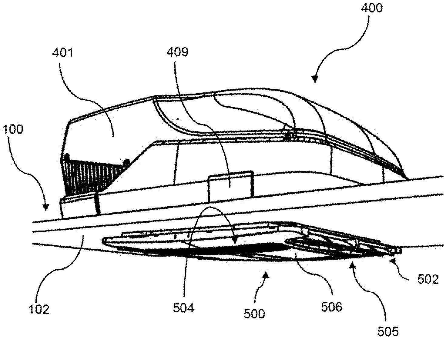
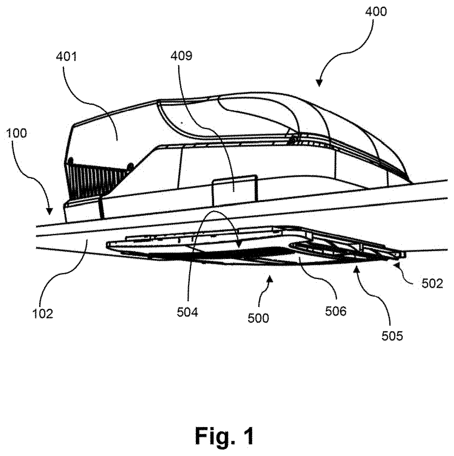
[0020] FIG. 1 illustrates a perspective view from obliquely below of an assembled modular climatization system according to an embodiment,
[0021] FIG. 2 illustrates a perspective view from obliquely above of the assembled modular climatization system of FIG. 1 with a solar panel,
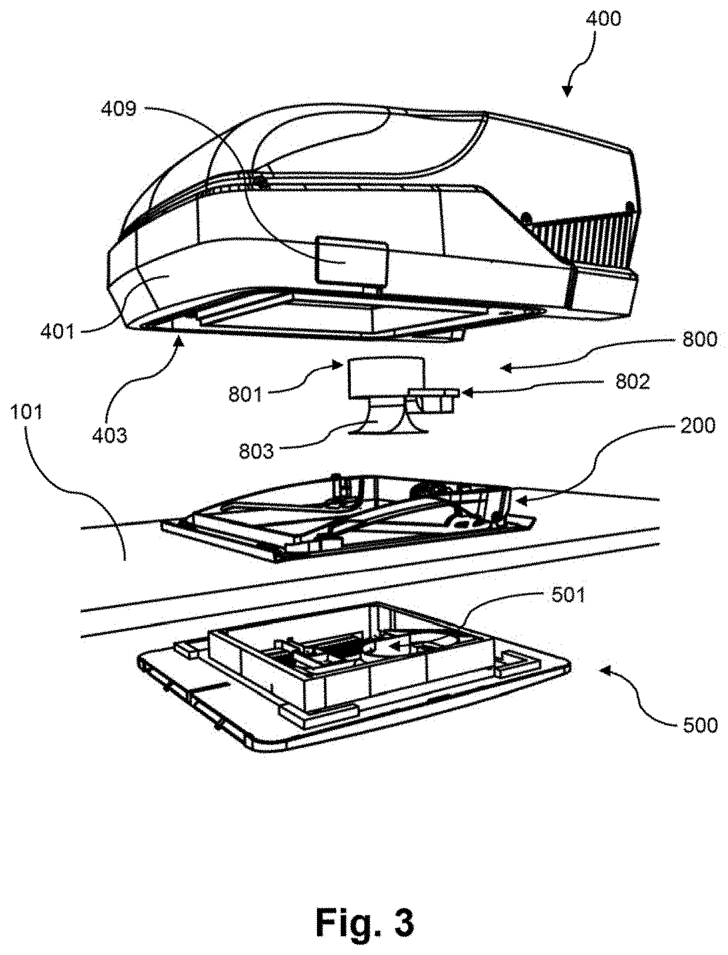
[0022] FIG. 3 illustrates an exploded view of the modular climatization system of FIG. 1,
[0023] FIG. 4 illustrates another exploded view of the modular climatization system of FIG. 1,
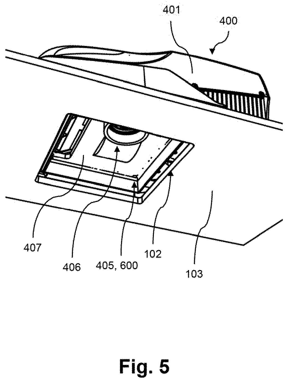
[0024] FIG. 5 illustrates a perspective view from below of the air conditioning unit of the modular climatization system of FIG. 1 placed on a roof cut-out,
[0025] FIG. 6 illustrates a lengthwise cross-sectional view through an air conditioning unit and an air distribution unit according to another embodiment,
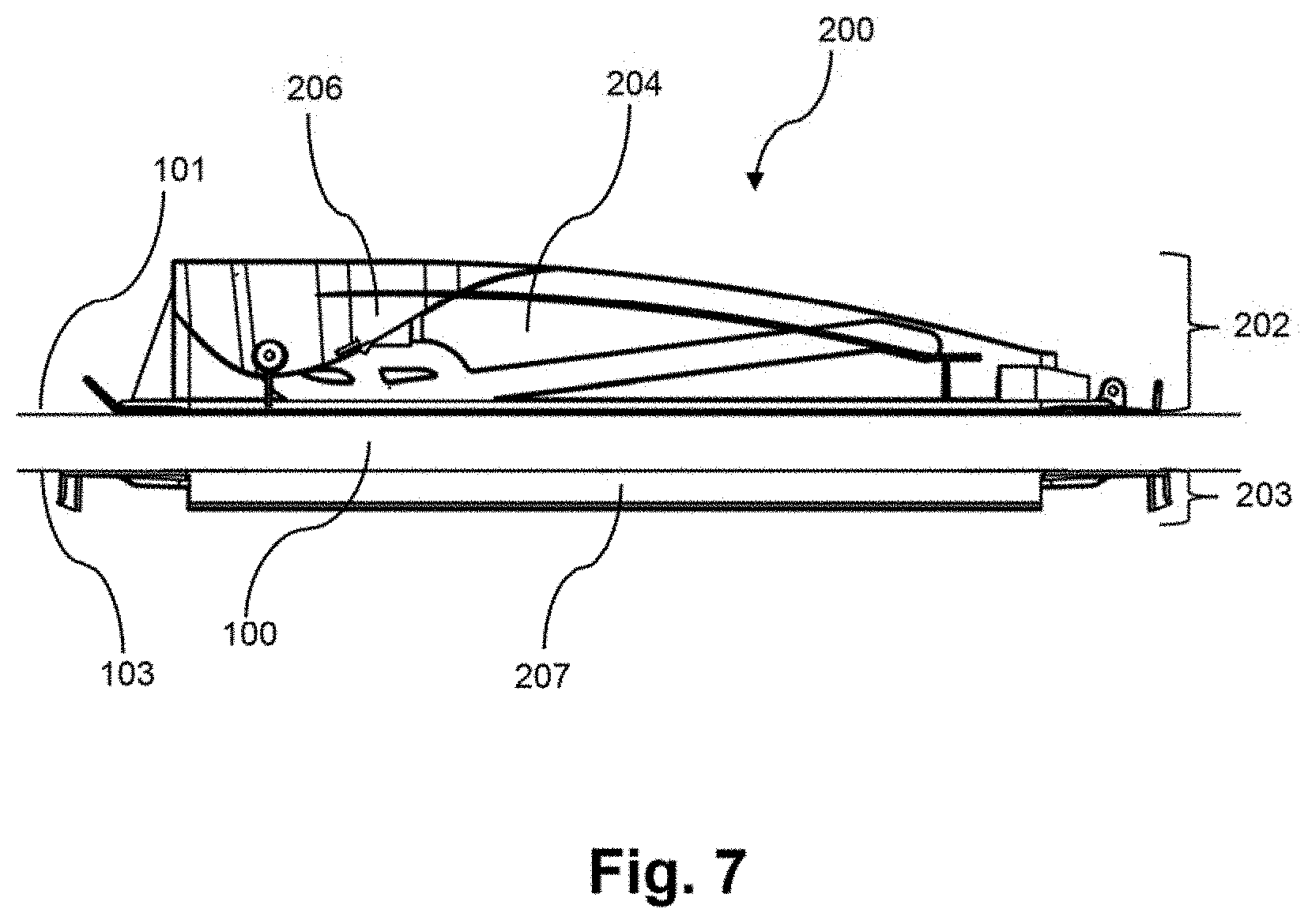
[0026] FIG. 7 illustrates a side view of a mounted mounting frame as shown in FIG. 3,
[0027] FIG. 8 illustrates a lengthwise cross-sectional view through a mounting frame and a part of the air conditioning unit according to the embodiment shown in FIG. 6,
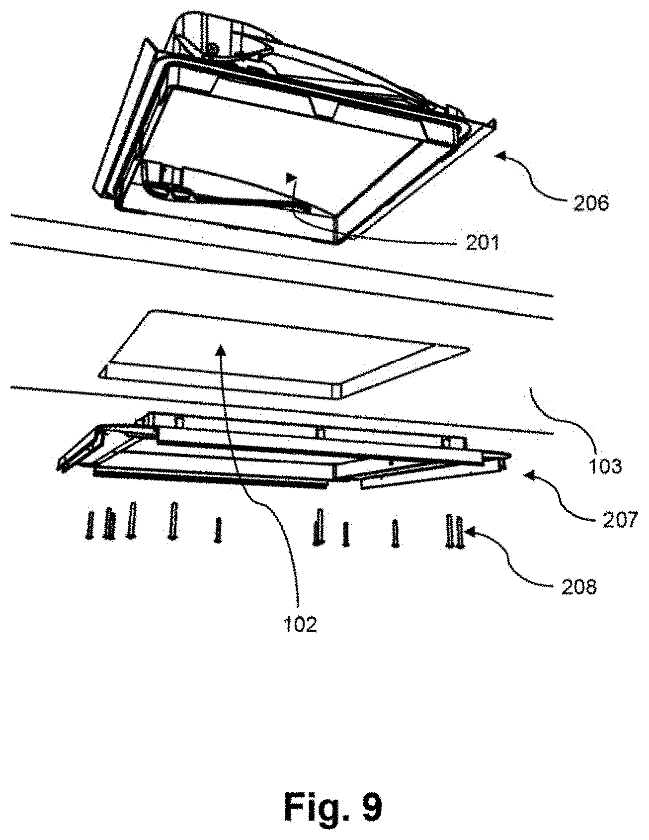
[0028] FIG. 9 illustrates an exploded view from below of the mounting frame shown in FIG. 7,
[0029] FIG. 10 illustrates steps of replacing a window with an air conditioning unit,
[0030] FIG. 11 illustrates steps of replacing a window with an air conditioning unit,
[0031] FIG. 12 illustrates steps of replacing a window with an air conditioning unit,
[0032] FIG. 13 illustrates steps of replacing a shading unit with an air distribution unit,
[0033] FIG. 14 illustrates steps of replacing a shading unit with an air distribution unit,
[0034] FIG. 15 illustrates a step of replacing a shading unit with an air distribution unit,
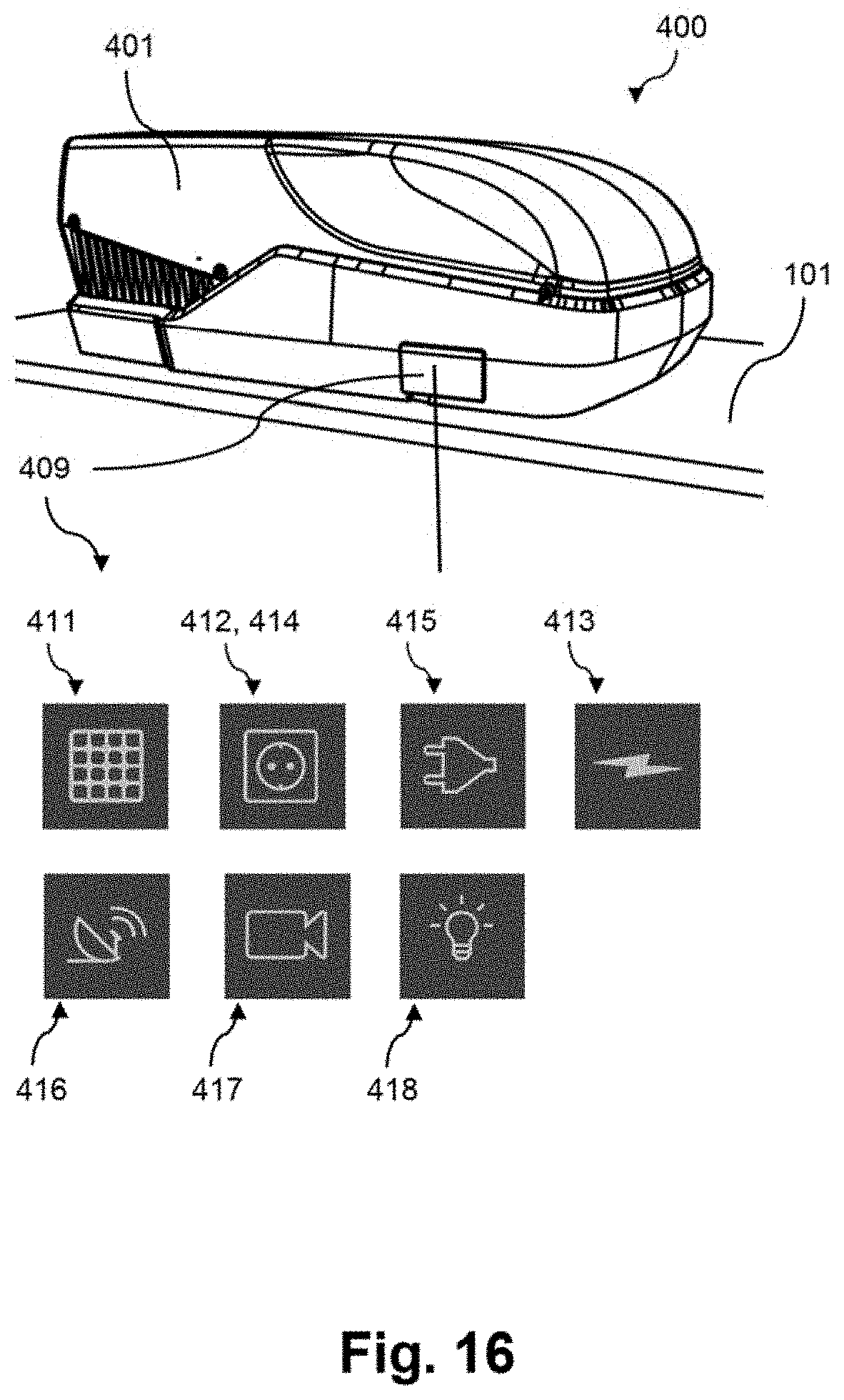
[0035] FIG. 16 illustrates a perspective view of an air conditioning unit with a connection port and different options for connection ports,
[0036] FIG. 17 illustrates a plan view onto an air distribution unit with an attachment portion for a module and several examples of modules, and
[0037] FIG. 18 illustrates a plan view onto a decorative window frame with a plurality of attachment portions for modules and the examples of modules as shown in FIG. 17.
DETAILED DESCRIPTION
[0038] In FIG. 1, a mounted version of the modular climatization system is shown with both the air conditioning unit 400 and the air distribution unit 500 being mounted. The air conditioning unit 400 is mounted outside the recreational vehicle, i.e. at the roof 100 of the recreational vehicle. The air conditioning unit 400 has a rigid outer cover 401 that protects the inside from environmental influences. The outer cover 401 has an aerodynamic shape. Further at the outside of the air conditioning unit 400 a cover covering one or more connection ports 409 are shown by which it is possible to connect external devices and/or to connect the air conditioning unit 400 to an external source of energy.
[0039] The roof 100 is illustrated as a flat board. However, typical shapes of roofs 100 of recreational vehicles are also compatible with the modular climatization system. Below the roof 100 at the ceiling 103, the air distribution unit 500 is mounted. Conditioned air is released at the air outlet 505 provided with air deflecting elements 502 at a side of the air distribution unit 500. The air distribution unit 500 is rather flat shaped in order to occupy less space inside the recreational vehicle. The conditioned air is released substantially horizontally along the ceiling 103 which is controlled by the air deflecting elements 502.
[0040] In a region near in the center of the air distribution unit 500, air inside the recreational vehicle is sucked in via the air inlet 504. At the air inlet 504, a filter cover 506 is provided that prevents dust or other particles from entering the air conditioning unit 400. The inside air is sucked substantially vertically upwards in order to prevent that the released conditioned air immediately re-enters the air conditioning unit 400.
[0041] In FIG. 2, the mounted modular climatization system of FIG. 1 is shown from above. The air conditioning unit 400 comprises a plurality of air vents 420 that provide for an effective heat exchange. As one possible external device that can be connected to the connection port 409, a solar panel 410 is exemplarily shown. The solar panel 410 is fixed at the outer roof surface 101 in front of the air conditioning unit 400 in the driving direction.
[0042] FIGS. 3 and 4 both show an exploded view of the modular climatization system of FIGS. 1 and 2. At the underside of the air conditioning unit 400, the gasket 404 surrounds the area of the opening of the roof 100. The gasket in this embodiment is of a flexible sealing material that is placed within a groove 419. Furthermore, the circumferential or peripheral cavity 403 lies concentrically with the gasket 404 at the underside of the air conditioning unit 400. In the cavity 403, space is provided for accommodating the mounting frame 200, particularly the upper component 206 of the mounting frame 200, which will be explained further below. The cavity 403 includes abutting portions that abut against the mounting frame 200 in order to secure the air conditioning unit 400 from lateral movement, i.e. in a direction in the plane defined by the opening 201 of the mounting frame 200.
[0043] Further, in the area enclosed by the cavity 403, the first pipe section 406 of the air conditioning unit 400 protrudes vertically downwards and provides an air flow path for the released conditioned air into the inside of the recreational vehicle.
[0044] The further component in the direction of the air flow path downwards is the adapter 800. The adapter 800 has on its upper side the third pipe section 801 which fits with the first pipe section 406 of the air conditioning unit 400. Further below, the adapter 800 has the fourth pipe section 802 and the air stream divider 803. Independent from the actual design of the adapter 800, in this embodiment, the adapter 800 is made as a one-piece plastic component. This has the advantage that air cannot leak. Due to manufacturing aspects, however, it may also be valuable on a case-by-case basis that the adapter 800 is composed of several pieces.
[0045] The adapter 800 is further connected via its fourth pipe section 802 with the air distribution unit 500, thereby completing the air flow path to the inside of the recreational vehicle. In the present embodiment, the second pipe section 501 of the air distribution unit 500 is not of such a circular shape the first pipe section 406 is. Therefore, the adapter 800 is rather asymmetrically shaped. In a mounted state, the fourth pipe section 802 engages with the second pipe section 501 and the air stream divider 803 immerses into the air distribution unit 500.
[0046] The air distribution unit 500 and the mounting frame 200 are designed in a way that, analogously to the air conditioning unit 400, the air distribution unit 500 can be sort of plugged onto the mounting frame 200 thereby preventing the air distribution unit 500 from lateral movement with respect to the mounting frame 200.
[0047] In FIG. 5, the bottom side of the air conditioning unit 400 is illustrated when seen through the roof cut-out 102. The first pipe section 406 and the base plate 407 are integrally formed as a one-piece component. Furthermore, fixing means 405 are provided in the area of the roof cut-out 102 or, more precisely, in the area of the opening 201 of the mounting frame 200. The fixing means 405 are present at the base plate 407 and are represented by bores 600. The bores 600 extend vertically so that the air distribution unit 500 can be fixed with screws 601 vertically through the opening 201 as will be described further below.
[0048] FIG. 6 displays a lengthwise cross-section through the air conditioning unit 400 and illustrates the air distribution unit 500 according to another embodiment. For a better overview, in FIG. 6 the mounting frame 200 is not shown. Furthermore, in FIG. 6 also the interior of the air conditioning unit 400 is left aside. Starting with the air conditioning unit 400, the concentric arrangement of the groove 419 for the gasket 404, the cavity 403 for accommodating the upper component 206 of the mounting frame 200 and the first pipe section 406 can be seen, all of which are formed together with the base plate 407 as one integral component. The cavity 403 includes substantially vertical walls serving as the abutting portions 402. Besides the first pipe section 406, a further opening 422 is provided in the base plate 407 and, corresponding thereto, in the air distribution unit 500 through which a further air flow path reaches for the air sucked in by the air conditioning unit 400.
[0049] At the transition from the base plate 407 to the first pipe section 406, the recess 408 accommodates the second pipe section 501 of the air distribution unit 500. The air distribution unit 500 is located at the ceiling 103 and is fixed to the air conditioning unit 400, while in FIG. 6 the respective fixing means are not shown either. The air distribution unit 500 includes the filter cover 506. The air stream dividing portion 508 of the air distribution unit 500 is located with its tip reaching through the second pipe section 501 and guides the conditioned air towards the air deflecting elements 502. Also, not shown in FIG. 6 are the means for providing the air flow path that is sucked in the air conditioning unit 400 through the base plate opening 422. The air flow paths through the first and second pipe sections 406, 501 are separate from each other.
[0050] In FIG. 7, a side view of the mounting frame 200 in the mounted state is shown. The outward facing side 202 of the mounting frame 200 is located at the outer roof surface 101 and the inward facing side 203 of the mounting frame 200 is located at the ceiling 103. At the upper component 206 of the mounting frame 200 is the first wall part 204. The lower component 207 also serves as securing means against lateral displacement of the air distribution unit 500 with respect to the mounting frame 200. The upper component 206 of the mounting frame 200 is, however, further designed to be connected, for example pivotally connected with the window 300, for example, via hinge pins 303 (shown in FIG. 11).
[0051] FIG. 8 illustrates the mounting frame 200 together with a part of the air conditioning unit 400 in a cross-sectional view. In FIG. 8 the first wall part 204 and the second wall part 205 are visible both representing substantially vertical elements. The wall parts 204 and 205 are designed to correspond to and to abut against the abutting portions 402 of the air conditioning unit 400. In the illustrated embodiment, the first wall part 204 is provided at the upper component 206 and the second wall part 205 is provided at the lower component 207 of the mounting frame 200. The first pipe section 406 reaches halfway through the opening 201, i.e. through about half of the thickness of an average roof 100.
[0052] In FIG. 9, an exploded view of the mounting frame 200 is shown. Upper component 206 and lower component 207 of the mounting frame 200 are fastened to each other by a plurality of screws 208. The opening 201 defined by the mounting frame 200 is slightly smaller than the roof cut-out 102. Thus, the screws 208 for coupling the upper and lower components 206 and 207 of the mounting frame 200 reach through the roof cut-out 102 and do not need to perforate the roof 100.
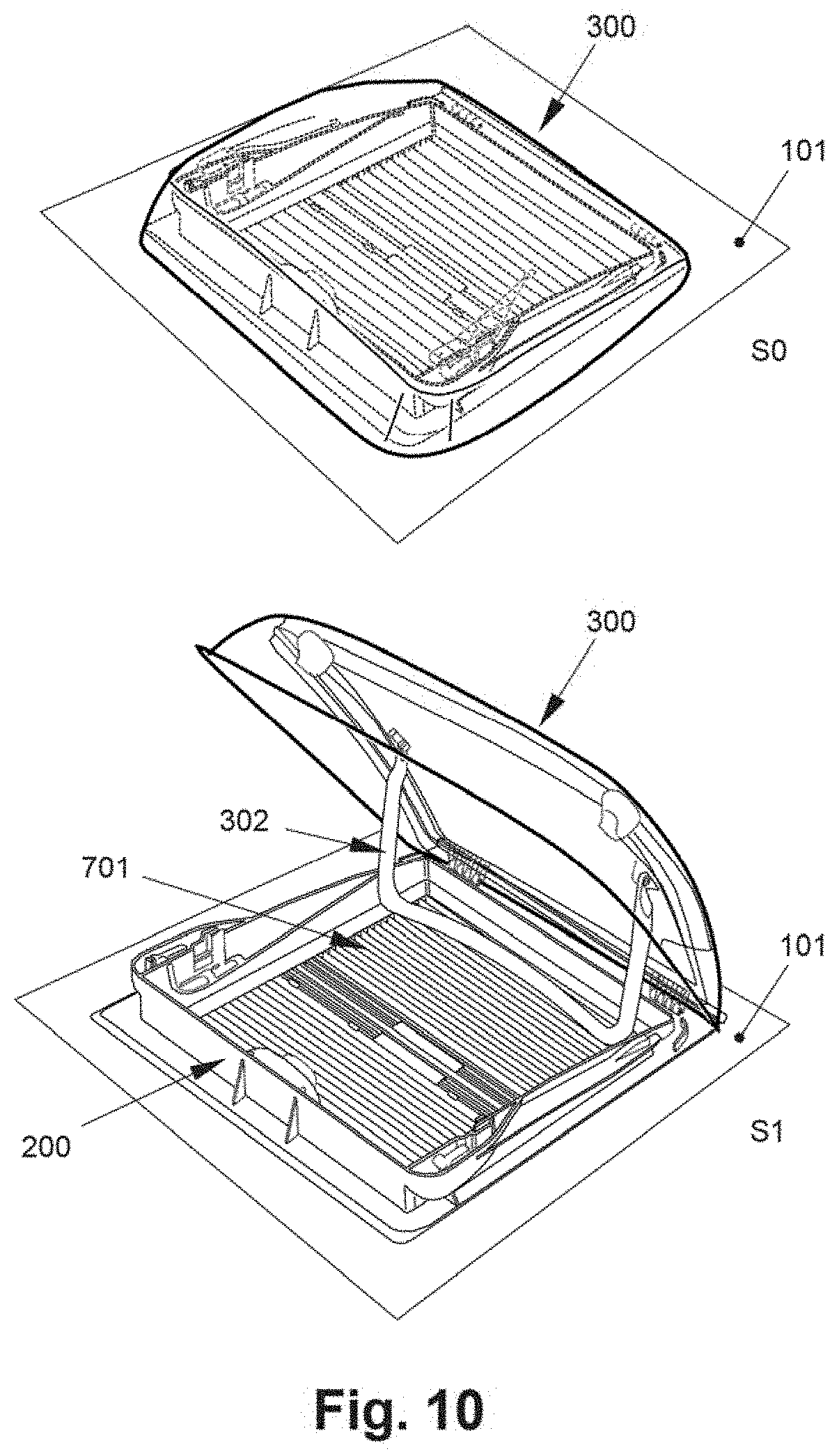
[0053] In FIGS. 10 to 15, a method of replacing the window 300 with the air conditioning unit 400 and the shading unit 700 with the air distribution unit 500, respectively, is exemplarily illustrated. First the window 300 is present at the outer roof surface 101, indicated as step S0 of FIG. 10.
[0054] In step S1 of FIG. 10, the window 300 is opened by means of the handle 302. The handle 302 functions at the same time as window casement stays. Through the opened window, the blinds 701 of the shading unit 700 are visible and the opened window reveals the mounting frame 200.
[0055] In step S2 of FIG. 11, the connection of the window 300 with the mounting frame 200 is disengaged by removing the hinge pins 303. Thus, the window 300 can be removed in step S3. In this embodiment, the window 300 can be removed by a rotational movement as indicated by the bold arrow in S3 of FIG. 11.
[0056] In S4 of FIG. 12, the mounting frame 200 with the window 300 being removed is shown and subsequently thereto, in S5 of FIG. 12, the base pan 421 of the air conditioning unit 400 is placed over the mounting frame 200. In this embodiment of the air conditioning unit 400, the base pan 421 is a one-piece component that includes the entire lower part of the outer cover 401 of the air conditioning unit 400, including the base plate 407, the groove 419, the cavity 403 and the first pipe section 406.
[0057] In S6 of FIG. 13 it is turned to the inside of the recreational vehicle and the removal of the shading unit 700 is shown, revealing the lower component 207 of the mounting frame 200. A part of the base pan 421 is visible through the opening 201. In S7 of FIG. 13, the mounting frame 200 with the shading unit 700 being removed is illustrated.
[0058] Finally, as shown in S8 and S9 of FIG. 14, the air distribution unit 500 is mounted to the air conditioning unit 400. First, the cable connection 507 between the air distribution unit 500 and the air conditioning unit 400 is established (see S8). Then, the air distribution unit 500 is placed over the lower component 207 of the mounting frame 200, followed by fixing the air distribution unit 500 with screws 601 through the bores 600 to the air conditioning unit 400. In the center of the air distribution unit 500, the underside of the air stream dividing portion 508 can be seen which, in S10 of FIG. 15 is finally covered by the filter cover 506.
[0059] With reference to FIG. 16, the connection port 409 is now explained in more detail. On a side of the outer cover 401 of the air conditioning unit 400 the connection port 409 is or the connection ports 409 are present near the outer roof surface 101. The connection ports 409 are coupled via the air conditioning unit 400 with a wire or wirelessly to the inside of the recreational vehicle, advantageously with a control interface (not shown) or with a power source. Additionally, a connection port may be just a cable to supply energy to the air conditioning unit 400.
[0060] The connected external device can be any suitable device. As exemplarily shown in FIG. 16, the connection ports 409 include a socket 412 for providing direct current.
[0061] According to another embodiment or additionally, the connection ports 409 include an inverter 413 and a socket 414 for providing alternating current.
[0062] According to another embodiment or additionally, the connection ports 409 include a plug 415 for plugging the air conditioning unit 400 to an external source of electricity.
[0063] According to another embodiment or additionally, the connection ports 409 include a solar panel connection port 411. This embodiment is already described above with reference to FIG. 2. The solar panel 410 is simply plugged in the connection ports 409 of the air conditioning unit 400.
[0064] According to another embodiment or additionally, the connection ports 409 include an antenna connection port 416. In this embodiment, an antenna, like a satellite dish, is placed on the roof 100 as usual and simply has to be plugged in the air conditioning unit 400
[0065] According to another embodiment or additionally, the connection ports 409 include a camera connection port 417. A camera can be plugged in the connection ports 409 at the air conditioning unit 400. The camera is thus supplied with electricity and can transfer its data via the air conditioning unit 400 to a receiving device (not shown) like the aforementioned interface (not shown).
[0066] According to another embodiment or additionally, the connection ports 409 include an external light connection port 418. Thereby, a light can be plugged in the connection ports 409 at the air conditioning unit 400. Preferably, the light intensity can be controlled via the interface (not shown).
[0067] In FIG. 17, a component part being the air distribution unit 500 is shown having the attachment portion 901 at the filter cover 506 aside the slots for the air inlet 504. The attachment portion in FIG. 17 is capable of attaching one module 900 which can be selected from a number of different modules 900. The module 900 to be connected to the air distribution unit 500 is clipped in at the attachment portion 901 by the user. The attachment portion 901 is equipped with a clip-fix or snap-in mechanism (not show) with which fixing and removing is easy to achieve.
[0068] Depending on what is currently needed, a module 900 can be selected from a temperature sensor 907, a pressure sensor 902, a camera 908, a motion sensor 909, a light sensor 904, a microphone 910, an air quality sensor, in particular a smoke sensor 905, a humidity sensor 906, a vibration sensor 911, a light source 903 and a speaker (not shown).
[0069] Each one of the sensors measuring certain events or parameter changes inside the recreational vehicle, like the temperature, can send the respective information to an external device (not shown) or to an interface (not shown).
[0070] In FIG. 18, the decorative window frame 301 is shown as the component part being equipped with the modules 900. In comparison with the air distribution unit 500 of FIG. 17, the window frame 301 has a plurality of such attachment portions 901 being illustrated by the dashed rectangles. Thereby, next to one, preferably a plurality of modules, e.g. two, three, four, five, six, seven or eight modules can be attached to the window frame 301 at the same time. Of course, there is no difference or limitation in selecting the modules 900 in comparison with the air distribution unit 500 as the component part equipped with the attachment portions 901.
[0071] Regardless of which part is the component part being equipped with the removably and exchangeably connected modules 900, the attachment portions 901 are equipped with electric contacts to provide power to the modules 900. As such, the modules 900 do not need a battery. In an advanced embodiment, the modules 900 are supplied with power from the same power source the air conditioning unit 400 has. Here, electric power is supplied via the mounting frame 200 to the air conditioning unit 400 and via the air conditioning unit 400 to the air distribution unit 500 or the decorative window frame 301, respectively, and to each attachment portion 901 present thereon. Alternatively, the power can be supplied directly from the mounting frame 200 to the air distribution unit 500 or the decorative window frame 301, respectively, and to each attachment portion 901 present thereon. In some examples, the attachment portions 901 for the modules 900 provide both power supply and signal transmission. For this purpose, electronic circuits for the signal transmission from and to the modules 900 are provided within the modular system, in particular, within the air distribution unit 500, the decorative window frame 301 and the mounting frame 200.
REFERENCE NUMERALS
[0072] 100 roof [0073] 101 outer roof surface [0074] 102 roof cut-out [0075] 103 ceiling [0076] 200 mounting frame [0077] 201 opening [0078] 202 outward facing side of the mounting frame [0079] 203 inward facing side of the mounting frame [0080] 204 first wall part [0081] 205 second wall part [0082] 206 upper component [0083] 207 lower component [0084] 208 screws (for assembling the mounting frame) [0085] 300 window [0086] 301 decorative window frame [0087] 302 handle [0088] 303 hinge pin [0089] 400 air conditioning unit [0090] 401 outer cover [0091] 402 abutting portion [0092] 403 cavity [0093] 404 gasket [0094] 405 fixing means at the air conditioning unit [0095] 406 first pipe section [0096] 407 base plate [0097] 408 recess [0098] 409 connection port [0099] 410 solar panel [0100] 411 solar panel connection port [0101] 412 socket DC [0102] 413 Inverter [0103] 414 socket AC [0104] 415 plug [0105] 416 antenna connection port [0106] 417 camera connection port [0107] 418 external light connection port [0108] 419 groove [0109] 420 air vents [0110] 421 base pan [0111] 422 opening in the base plate [0112] 500 air distribution unit [0113] 501 second pipe section [0114] 502 air deflecting elements [0115] 503 fixing means at the air distribution unit [0116] 504 air inlet [0117] 505 air outlet [0118] 506 filter cover [0119] 507 cable connection [0120] 508 air stream dividing portion [0121] 600 bore [0122] 601 screw [0123] 700 shading unit [0124] 701 blind [0125] 800 adapter [0126] 801 third pipe section [0127] 802 fourth pipe section [0128] 803 air stream divider [0129] 900 module [0130] 901 attachment portion [0131] 902 pressure sensor [0132] 903 light source [0133] 904 light sensor [0134] 905 smoke sensor [0135] 906 humidity sensor [0136] 907 temperature sensor [0137] 908 camera [0138] 909 motion sensor [0139] 910 microphone [0140] 911 vibration sensor
* * * * *
D00000
D00001
D00002
D00003
D00004
D00005
D00006
D00007
D00008
D00009
D00010
D00011
D00012

D00013

D00014

D00015

D00016
D00017

D00018

XML
uspto.report is an independent third-party trademark research tool that is not affiliated, endorsed, or sponsored by the United States Patent and Trademark Office (USPTO) or any other governmental organization. The information provided by uspto.report is based on publicly available data at the time of writing and is intended for informational purposes only.
While we strive to provide accurate and up-to-date information, we do not guarantee the accuracy, completeness, reliability, or suitability of the information displayed on this site. The use of this site is at your own risk. Any reliance you place on such information is therefore strictly at your own risk.
All official trademark data, including owner information, should be verified by visiting the official USPTO website at www.uspto.gov. This site is not intended to replace professional legal advice and should not be used as a substitute for consulting with a legal professional who is knowledgeable about trademark law.