Robot Multi-degree-of-freedom Clamper
LIU; Jinguo ; et al.
U.S. patent application number 16/957720 was filed with the patent office on 2021-03-04 for robot multi-degree-of-freedom clamper. The applicant listed for this patent is SHENYANG INSTITUTE OF AUTOMATION, CHINESE ACADEMY OF SCIENCES. Invention is credited to Jinguo LIU, Yunjun LIU.
| Application Number | 20210060796 16/957720 |
| Document ID | / |
| Family ID | 1000005260217 |
| Filed Date | 2021-03-04 |


| United States Patent Application | 20210060796 |
| Kind Code | A1 |
| LIU; Jinguo ; et al. | March 4, 2021 |
ROBOT MULTI-DEGREE-OF-FREEDOM CLAMPER
Abstract
The present invention relates to a robot multi-degree-of-freedom damper. A clamping jaw supporting frame is installed on a bottom plate; a short stroke biaxial cylinder is installed on the clamping jaw supporting frame; an output end is connected with a pneumatic clamping jaw A; a clamping jaw finger A is connected with an output end of the pneumatic clamping jaw A; a long stroke biaxial cylinder is installed on the bottom plate; the output end of the long stroke biaxial cylinder is connected with a pneumatic clamping jaw B; a clamping jaw finger B is connected with the output end of the pneumatic clamping jaw B; a pneumatic clamping jaw C is installed on the clamping jaw supporting frame and positioned between the pneumatic clamping jaw A and the pneumatic clamping jaw B; a clamping jaw finger C is connected with the output end of the pneumatic clamping jaw C; the clamping jaw finger A and the pneumatic clamping jaw A are driven by the short stroke biaxial cylinder to move back and forth on the clamping jaw supporting frame; and the clamping jaw finger B and the pneumatic clamping jaw B are driven by the long stroke biaxial cylinder to move back and forth on the bottom plate. The present invention adopts the humanoid configuration design, can realize the automatic docking of the spring return type quick joints, and has unique appearance, novel structure, simple control and strong working reliability.
| Inventors: | LIU; Jinguo; (Shenyang, Liaoning, CN) ; LIU; Yunjun; (Shenyang, Liaoning, CN) | ||||||||||
| Applicant: |
|
||||||||||
|---|---|---|---|---|---|---|---|---|---|---|---|
| Family ID: | 1000005260217 | ||||||||||
| Appl. No.: | 16/957720 | ||||||||||
| Filed: | December 20, 2018 | ||||||||||
| PCT Filed: | December 20, 2018 | ||||||||||
| PCT NO: | PCT/CN2018/122219 | ||||||||||
| 371 Date: | June 24, 2020 |
| Current U.S. Class: | 1/1 |
| Current CPC Class: | B25J 15/086 20130101; B64G 1/646 20130101; B25J 15/103 20130101; B25J 15/0009 20130101; B25J 15/0033 20130101 |
| International Class: | B25J 15/00 20060101 B25J015/00; B25J 15/08 20060101 B25J015/08; B25J 15/10 20060101 B25J015/10 |
Foreign Application Data
| Date | Code | Application Number |
|---|---|---|
| Dec 25, 2017 | CN | 201711422333.3 |
Claims
1. A robot multi-degree-of-freedom damper, characterized by comprising a clamping jaw finger A(1), a pneumatic clamping jaw A(2), a short stroke biaxial cylinder (4), a clamping jaw supporting frame (5), a bottom plate (6), a long stroke biaxial cylinder (7), a pneumatic clamping jaw B(9), a pneumatic clamping jaw C(10), a clamping jaw finger B(11) and a clamping jaw finger C(12), wherein the clamping jaw supporting frame (5) is installed on the bottom plate (6); the short stroke biaxial cylinder (4) is installed on the clamping jaw supporting frame (5); an output end is connected with the pneumatic clamping jaw A(2); the clamping jaw finger A(1) is connected with an output end of the pneumatic clamping jaw A(2); the long stroke biaxial cylinder (7) is installed on the bottom plate (6), and positioned below the short stroke biaxial cylinder (4); the output end of the long stroke biaxial cylinder (7) is connected with the pneumatic clamping jaw B(9); the clamping jaw finger B(11) is connected with the output end of the pneumatic clamping jaw B(9); the pneumatic clamping jaw C(10) is installed on the clamping jaw supporting frame (5) and positioned between the pneumatic clamping jaw A(2) and the pneumatic clamping jaw B(9); the clamping jaw finger C(12) is connected with the output end of the pneumatic clamping jaw C(10); the clamping jaw finger A(1) and the pneumatic clamping jaw A(2) are driven by the short stroke biaxial cylinder (4) to move back and forth on the clamping jaw supporting frame (5); the clamping jaw finger B(11) and the pneumatic clamping jaw B(9) are driven by the long stroke biaxial cylinder (7) to move back and forth on the bottom plate (6); the clamping jaw finger A(1) and the clamping jaw finger C(12) clamp a female quick joint (14); the clamping jaw finger B(11) clamps a male quick joint (13); and the docking of the male quick joint (13) and the female quick joint (14) is realized through the driving of the long stroke biaxial cylinder (7) and the short stroke biaxial cylinder (4).
2. The robot multi-degree-of-freedom clamper according to claim 1, characterized in that entirely rhombic openings for clamping a prism are formed on both sides of a clamping end of the clamping jaw finger A(1).
3. The robot multi-degree-of-freedom damper according to claim 1, characterized in that each side of a clamping end of the clamping jaw finger C(12) is a semicircular opening; and entirely circular openings for clamping the cylinder are formed on both sides of the clamping end.
4. The robot multi-degree-of-freedom damper according to claim 1, characterized in that the clamping jaw finger A(1) and the pneumatic clamping jaw A(2), and the clamping jaw finger B(11) and the pneumatic clamping jaw B(8) are respectively positioned on both sides of the clamping jaw finger C(12) and the pneumatic clamping jaw C(10).
5. The robot multi-degree-of-freedom damper according to claim 1, characterized in that the pneumatic clamping jaw A(2) is connected with the output end of the short stroke biaxial cylinder (4)through a clamping jaw fixing plate A(3); one end of the clamping jaw fixing plate A(3) is connected with the pneumatic clamping jaw A(2), and the other end is connected with the output end of the short stroke biaxial cylinder (4); the pneumatic clamping jaw B(9) is connected with the output end of the long stroke biaxial cylinder (7) through a clamping jaw fixing plate B(8); one end of the clamping jaw fixing plate B(7) is connected with the pneumatic clamping jaw B(9), and the other end is connected with the output end of the long stroke biaxial cylinder (7).
6. The robot multi-degree-of-freedom damper according to claim 5, characterized in that the clamping jaw fixing plate A(3) has the same shape and structure as those of the clamping jaw fixing plate B(8); and the shape is a cuboid structure and an oval hole (15) for reducing self-weight and increasing a ratio of bearing capacity to weight is formed in the middle.
7. The robot multi-degree-of-freedom damper according to claim 1, characterized in that the projection of the biaxial centerline of the short stroke biaxial cylinder (4) in the axial direction and the projection of the biaxial centerline of the long stroke biaxial cylinder (7) in the axial direction on the bottom plate (6) are respectively collinear.
8. The robot multi-degree-of-freedom damper according to claim 1, characterized in that both sides in the lengthwise direction of the clamping jaw supporting frame (5) are fixedly connected to the bottom plate (6); the short stroke biaxial cylinder (4) is fixedly connected to an upper surface of the rear end of the clamping jaw supporting frame (5); the front end of the clamping jaw supporting frame (5) extends upwards to form an installing plate (18); and the pneumatic clamping jaw C(10) is fixedly connected to one side of the installing plate (18) which faces the pneumatic clamping jaw B(9).
9. The robot multi-degree-of-freedom clamper according to claim 1, characterized in that a weight reducing slot hole (16) and a guide slot (17) for guiding the motion of the pneumatic clamping jaw B(9) are respectively formed in the bottom plate (6).
Description
TECHNICAL FIELD
[0001] The present invention relates to a clamper, particularly to a robot multi-degree-of-freedom damper.
BACKGROUND
[0002] Propellant filling is an important link before rocket launching. The space powers in the world have been paying close attention to the research of automatic docking and disassembling technology of propellant filling pipeline joints. Docking and disassembling of pipeline joint connectors is a high risk link in filling, and is also a primary problem to be solved in realizing the automation of the filling process. In the work of adding and discharging the propellant of a launch vehicle, connection, disassembling and transportation of various propellant pipelines, and the cleaning work of propellant filling pipes and propellant storage tanks are extremely dangerous tasks, and can easily cause casualties. Therefore, research of an automatic filling robot technology is conducive to shortening preparation time before launching, decreasing workload and reducing risks of emergency produced by misoperation of service crew; improving the safety of rockets and operators; and enhancing the reliability and safety of the system, and has important significance to alleviating the labor intensity of the operators.
[0003] Meanwhile, at present, on the production line of the air-conditioning industry, the pressure-tightness test, vacuum pumping, coolant infusion, commercial inspection operation test and other procedures of the pipeline should be performed every day. The existing connection of a quick joint of the pipeline, a hydraulic valve and an air pressure valve is manual docking by staff, which consumes large manpower. Meanwhile, due to long manual operation time and low working efficiency, the time wasting phenomenon that a workpiece waits for people or people wait for the workpiece even appears.
SUMMARY
[0004] In view of the above problems, the purpose of the present invention is to provide a robot multi-degree-of-freedom damper. The multi-degree-of-freedom damper adopts humanoid configuration design, can realize automatic docking for a spring return type quick joint, and has unique appearance, novel structure, simple control and strong working reliability.
[0005] The purpose of the present invention is realized by the following technical solution:
[0006] The present invention comprises a clamping jaw finger A, a pneumatic clamping jaw A, a short stroke biaxial cylinder, a clamping jaw supporting frame, a bottom plate, a long stroke biaxial cylinder, a pneumatic clamping jaw B, a pneumatic clamping jaw C, a clamping jaw finger B and a clamping jaw finger C, wherein the clamping jaw supporting frame is installed on the bottom plate; the short stroke biaxial cylinder is installed on the clamping jaw supporting frame; an output end is connected with the pneumatic clamping jaw A; the clamping jaw finger A is connected with an output end of the pneumatic clamping jaw A; the long stroke biaxial cylinder is installed on the bottom plate, and positioned below the short stroke biaxial cylinder; the output end of the long stroke biaxial cylinder is connected with the pneumatic clamping jaw B; the clamping jaw finger B is connected with the output end of the pneumatic clamping jaw B; the pneumatic clamping jaw C is installed on the clamping jaw supporting frame and positioned between the pneumatic clamping jaw A and the pneumatic clamping jaw B; the clamping jaw finger C is connected with the output end of the pneumatic clamping jaw C; the clamping jaw finger A and the pneumatic clamping jaw A are driven by the short stroke biaxial cylinder to move back and forth on the clamping jaw supporting frame; the clamping jaw finger B and the pneumatic clamping jaw B are driven by the long stroke biaxial cylinder to move back and forth on the bottom plate; the clamping jaw finger A and the clamping jaw finger C clamp a female quick joint; the clamping jaw finger B clamps a male quick joint; and the docking of the male quick joint and the female quick joint is realized through the driving of the long stroke biaxial cylinder and the short stroke biaxial cylinder.
[0007] Entirely rhombic openings for clamping a prism are formed on both sides of a clamping end of the clamping jaw finger A.
[0008] Each side of a clamping end of the clamping jaw finger C is a semicircular opening; and entirely circular openings for clamping the cylinder are formed on both sides of the clamping end.
[0009] The clamping jaw finger A and the pneumatic clamping jaw A, and the clamping jaw finger B and the pneumatic clamping jaw B are respectively positioned on both sides of the clamping jaw finger C and the pneumatic clamping jaw C.
[0010] The pneumatic clamping jaw A is connected with the output end of the short stroke biaxial cylinder through a clamping jaw fixing plate A; one end of the clamping jaw fixing plate A is connected with the pneumatic clamping jaw A, and the other end is connected with the output end of the short stroke biaxial cylinder; the pneumatic clamping jaw B is connected with the output end of the long stroke biaxial cylinder through a clamping jaw fixing plate B; one end of the clamping jaw fixing plate B is connected with the pneumatic clamping jaw B, and the other end is connected with the output end of the long stroke biaxial cylinder; the clamping jaw fixing plate A has the same shape and structure as those of the clamping jaw fixing plate B; and the shape is a cuboid structure and an oval hole for reducing self-weight and increasing a ratio of bearing capacity to weight is formed in the middle.
[0011] The projection of the biaxial centerline of the short stroke biaxial cylinder in the axial direction and the projection of the biaxial centerline of the long stroke biaxial cylinder in the axial direction on the bottom plate are respectively collinear.
[0012] Both sides in the lengthwise direction of the clamping jaw supporting frame are fixedly connected to the bottom plate; the short stroke biaxial cylinder is fixedly connected to an upper surface of the rear end of the clamping jaw supporting frame; the front end of the clamping jaw supporting frame extends upwards to form an installing plate; and the pneumatic clamping jaw C is fixedly connected to one side of the installing plate which faces the pneumatic clamping jaw B.
[0013] A weight reducing slot hole and a guide slot for guiding the motion of the pneumatic clamping jaw B are respectively formed in the bottom plate.
[0014] The present invention has the advantages and positive effects that:
[0015] 1. The present invention adopts the humanoid configuration design, and has novel and unique structure.
[0016] 2. The clamping jaw fingers of the present invention are designed as semicircle and rhombus, and have strong specificity and stable and reliable clamping.
[0017] 3. The middle clamping jaw of the present invention is fixed, which reduces one degree of freedom and realizes easy control and high docking accuracy.
[0018] 4. The structures of the clamping jaw supporting frame and the bottom plate of the present invention are locally hollowed out, so that the weight is light and the structures are compact.
[0019] 5. The present invention has five degrees of freedom and can realize clamping and automatic docking of the quick joints.
DESCRIPTION OF DRAWINGS
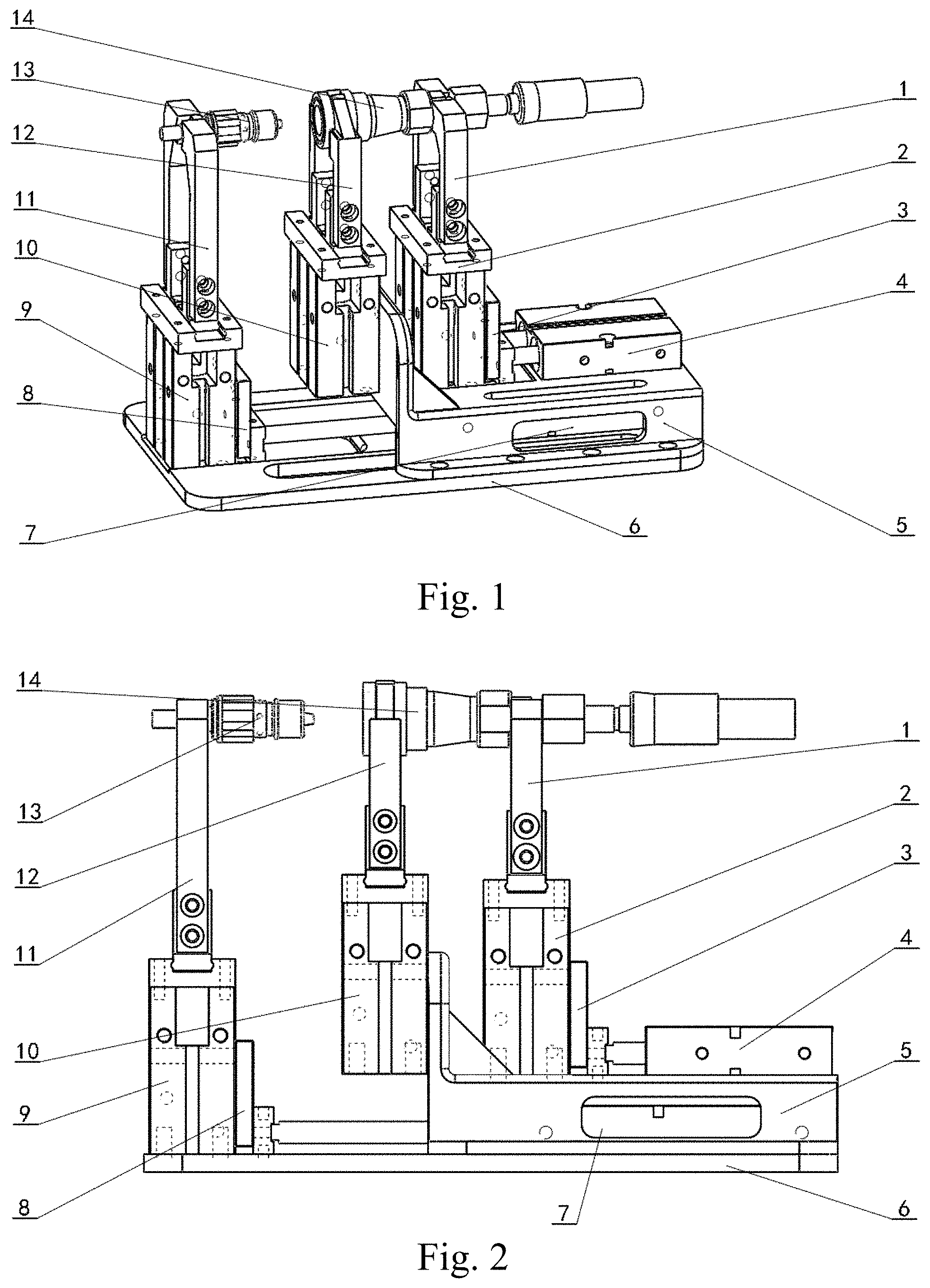
[0020] FIG. 1 is an overall structural schematic diagram of the present invention;
[0021] FIG. 2 is a structural front view of the present invention;
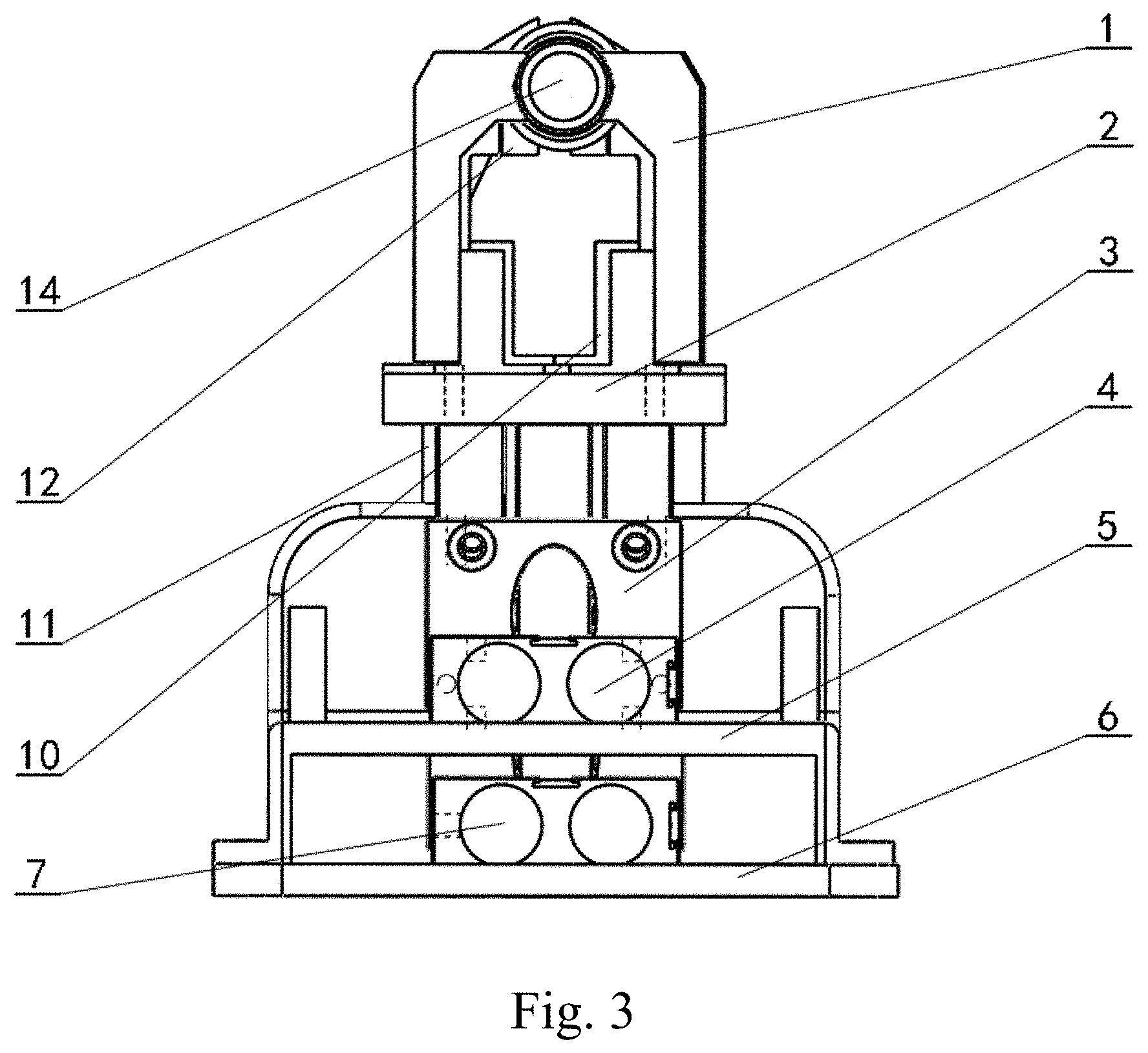
[0022] FIG. 3 is a structural right view of the present invention;
[0023] FIG. 4 is a structural top view of the present invention;
[0024] FIG. 5 is a structural schematic diagram of a clamping jaw fixing plate of the present invention;
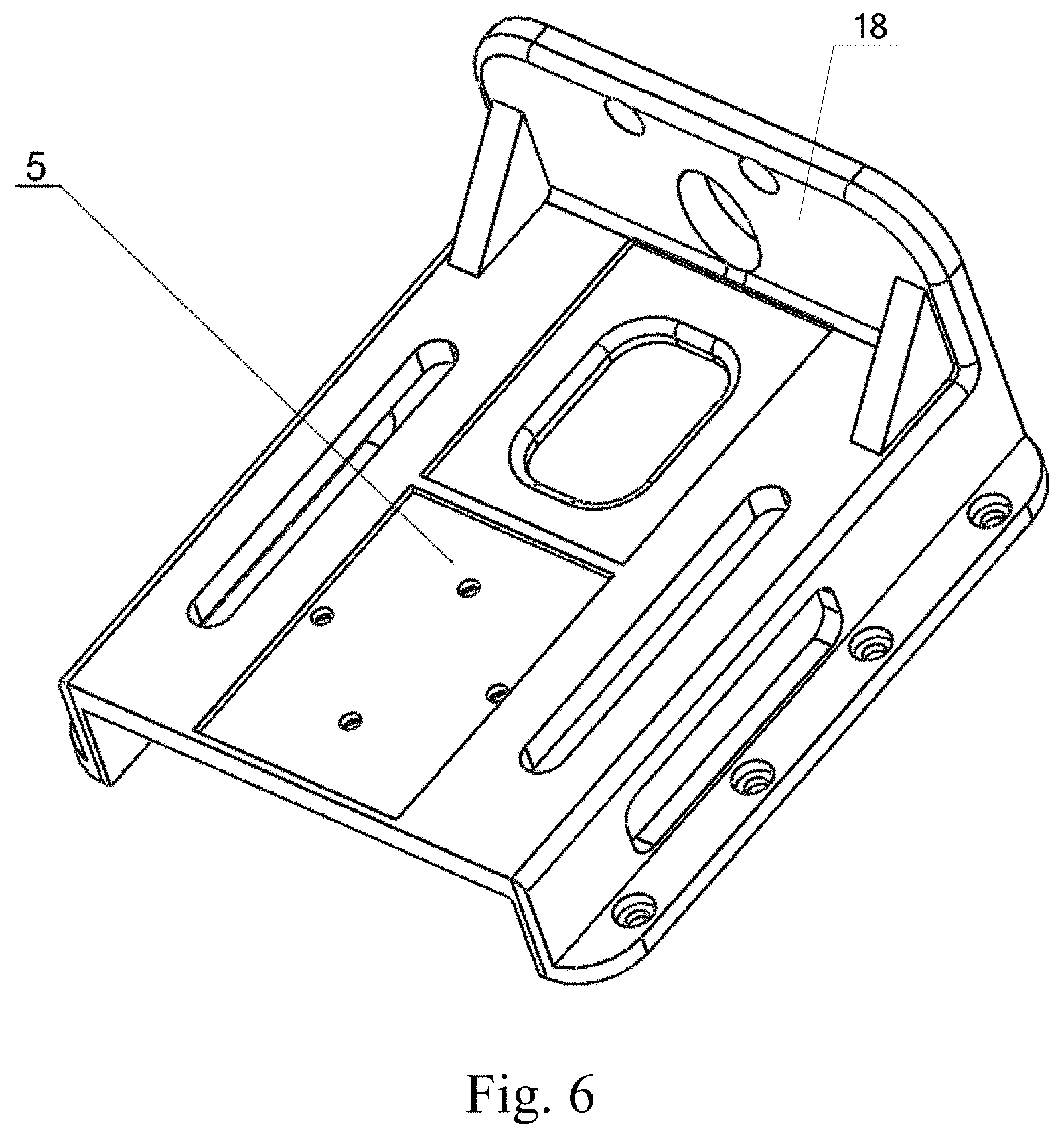
[0025] FIG. 6 is a structural schematic diagram of a clamping jaw supporting frame of the present invention;
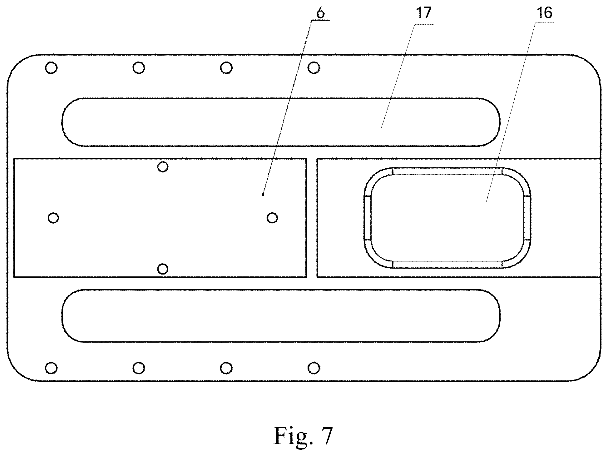
[0026] FIG. 7 is a structural schematic diagram of a bottom plate of the present invention;
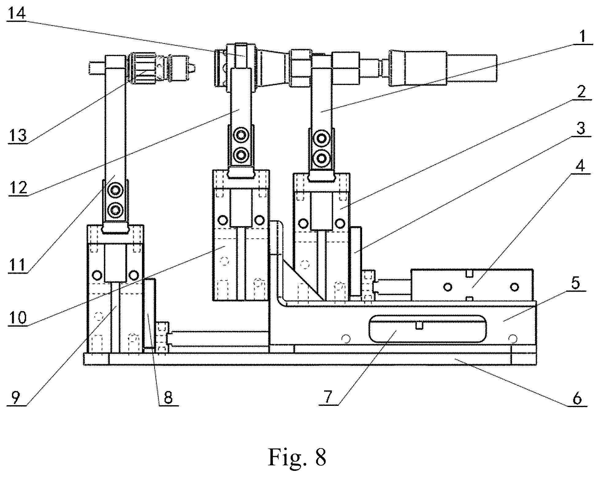
[0027] FIG. 8 is a schematic diagram I of an automatic docking process of the present invention; and
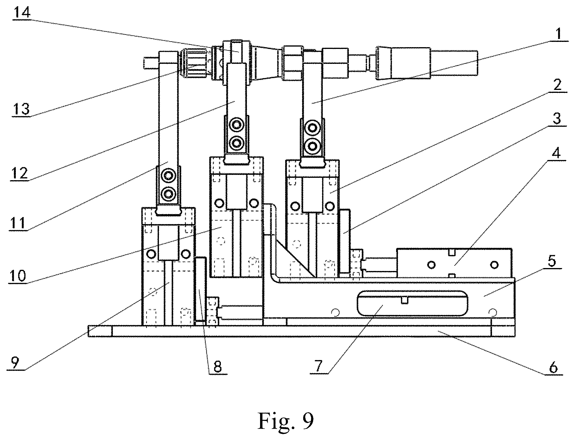
[0028] FIG. 9 is a schematic diagram II of an automatic docking process of the present invention.
[0029] Wherein: 1 clamping jaw finger A; 2 pneumatic clamping jaw A; 3 clamping jaw fixing plate A; 4 short stroke biaxial cylinder; 5 clamping jaw supporting frame; 6 bottom plate; 7 long stroke biaxial cylinder; 8 clamping jaw fixing plate B; 9 pneumatic clamping jaw B; 10 pneumatic clamping jaw C; 11 clamping jaw finger B; 12 clamping jaw finger C; 13 male quick joint; 14 female quick joint; 15 oval hole; 16 weight reducing slot hole; 17 guide slot; and 18 installing plate.
DETAILED DESCRIPTION
[0030] The present invention is further detailed below in combination with the drawings.
[0031] As shown in FIG. 1 to FIG. 4, the present invention comprises a clamping jaw finger A1, a pneumatic clamping jaw A2, a clamping jaw fixing plate A3, a short stroke biaxial cylinder 4, a clamping jaw supporting frame 5, a bottom plate 6, a long stroke biaxial cylinder 7, a clamping jaw fixing plate B8, a pneumatic clamping jaw B9, a pneumatic clamping jaw C10, a clamping jaw finger B11 and a clamping jaw finger B12, wherein the clamping jaw supporting frame 5 is installed on the bottom plate 6; the short stroke biaxial cylinder 4 is installed on the clamping jaw supporting frame 5; the pneumatic clamping jaw A2 is connected with an output end of the short stroke biaxial cylinder 4 through the clamping jaw fixing plate A3; one end of the clamping jaw fixing plate A3 is connected with the pneumatic clamping jaw A2 through a bolt, and the other end is connected with the output end of the short stroke biaxial cylinder 4 through the bolt; and the clamping jaw finger A1 is connected with the output end of the pneumatic clamping jaw A2. The long stroke biaxial cylinder 7 is installed on the bottom plate 6, and positioned below the short stroke biaxial cylinder 4; the pneumatic clamping jaw B9 is connected with the output end of the long stroke biaxial cylinder 7 through the clamping jaw fixing plate B8; one end of the clamping jaw fixing plate B7 is connected with the pneumatic clamping jaw B9 through the bolt, and the other end is connected with the output end of the long stroke biaxial cylinder 7 through the bolt; and the clamping jaw finger B11 is connected with the output end of the pneumatic clamping jaw B9. The pneumatic clamping jaw C10 is installed on the clamping jaw supporting frame 5 and positioned between the pneumatic clamping jaw A2 and the pneumatic clamping jaw B9; and the clamping jaw finger C12 is connected with the output end of the pneumatic clamping jaw C10. Entirely rhombic openings for clamping a prism target are designed on both sides of a clamping end of the clamping jaw finger A1. Each side of a clamping end of the clamping jaw finger C12 is designed as a semicircular opening; and entirely circular openings for clamping the cylinder structure are formed on both sides of the clamping end. The clamping jaw finger A1 and the clamping jaw finger C12 have strong specificity and stable and reliable clamping. The clamping jaw finger A1 and the pneumatic clamping jaw A2, and the clamping jaw finger B11 and the pneumatic clamping jaw B8 are respectively positioned on both sides of the clamping jaw finger C12 and the pneumatic clamping jaw C10. The clamping jaw finger A1 and the pneumatic clamping jaw A2 are driven by the short stroke biaxial cylinder 4 to move back and forth on the clamping jaw supporting frame 5; and the clamping jaw finger B11 and the pneumatic clamping jaw B9 are driven by the long stroke biaxial cylinder 7 to move back and forth on the bottom plate 6.
[0032] As shown in FIG. 5, the clamping jaw fixing plate A3 has the same shape and structure as those of the clamping jaw fixing plate B8; and the shape is a cuboid structure and an oval hole 15 for reducing self-weight and increasing a ratio of bearing capacity to weight is formed in the middle.
[0033] As shown in FIG. 6, both sides in the lengthwise direction of the clamping jaw supporting frame 5 are fixedly connected to the bottom plate 6; the short stroke biaxial cylinder 4 is fixedly connected to an upper surface of the rear end of the clamping jaw supporting frame 5; the front end of the clamping jaw supporting frame 5 extends upwards to form an installing plate 18; and the pneumatic clamping jaw C10 is fixedly connected to one side of the installing plate 18 which faces the pneumatic clamping jaw B9. Holes and slots with different sizes and shapes are respectively formed on the upper surface and the side surface of the clamping jaw supporting frame 5 for reducing self-weight and arrangement of air pipe lines.
[0034] As shown in FIG. 7, a weight reducing slot hole 16 and a guide slot 17 for guiding the motion of the pneumatic clamping jaw B9 are respectively formed in the bottom plate 6. The bottom plate 6 has light weight and compact structure and is used for fixedly supporting the long stroke biaxial cylinder 7 and the clamping jaw supporting frame 5.
[0035] The projection of the biaxial centerline of the short stroke biaxial cylinder 4 in the axial direction and the projection of the biaxial centerline of the long stroke biaxial cylinder 7 in the axial direction on the bottom plate 6 are respectively collinear.
[0036] The present invention has the operating principle that:
[0037] The present invention has five degrees of freedom, i.e., the clamping of the clamping jaw finger A1, the clamping jaw finger B11 and the clamping jaw finger C12, the motion of the pneumatic clamping jaw A2 and the clamping jaw finger A1 under the drive of the short stroke biaxial cylinder 4, and the motion of the pneumatic clamping jaw B9 and the clamping jaw finger B11 under the drive of the long stroke biaxial cylinder 7.
[0038] The clamping jaw finger A1 and the clamping jaw finger C12 simultaneously clamp a spring return type female quick joint 14, and the clamping jaw finger B11 clamps a spring return type male quick joint 13. The short stroke biaxial cylinder 4 is operated; and the clamping jaw fixing plate A3 pushes the pneumatic clamping jaw A2 to extend and reach a set distance so that the spring return type female quick joint 14 is unlocked, as shown in FIG. 8. Then, the long stroke biaxial cylinder 7 is operated; and the clamping jaw fixing plate B8 pulls the pneumatic clamping jaw B9 so that the spring return type male quick joint 13 is steadily inserted into the spring return type female quick joint 14, as shown in FIG. 9. Finally, the short stroke biaxial cylinder 4 is pulled back to reach an initial position, and the pneumatic clamping jaw A2, the pneumatic clamping jaw B9 and the pneumatic clamping jaw C10 respectively drive to release the clamping jaw finger A1, the clamping jaw finger B11 and the clamping jaw finger C12 to complete the automatic docking of the spring return type quick joints.
[0039] The present invention drives the retractable and pneumatic clamping jaws of the long stroke biaxial cylinder and the short stroke biaxial cylinder to open and close through air pressure, to realize the automatic docking of the spring return type quick joints. The present invention adopts the humanoid configuration design, can realize the automatic docking of the spring return type quick joints, and has unique appearance, novel structure, simple control and strong working reliability.
* * * * *
D00000
D00001
D00002
D00003
D00004
D00005
D00006
D00007
XML
uspto.report is an independent third-party trademark research tool that is not affiliated, endorsed, or sponsored by the United States Patent and Trademark Office (USPTO) or any other governmental organization. The information provided by uspto.report is based on publicly available data at the time of writing and is intended for informational purposes only.
While we strive to provide accurate and up-to-date information, we do not guarantee the accuracy, completeness, reliability, or suitability of the information displayed on this site. The use of this site is at your own risk. Any reliance you place on such information is therefore strictly at your own risk.
All official trademark data, including owner information, should be verified by visiting the official USPTO website at www.uspto.gov. This site is not intended to replace professional legal advice and should not be used as a substitute for consulting with a legal professional who is knowledgeable about trademark law.