Rebounding Device For Sports Ball
FEDON; Shane ; et al.
U.S. patent application number 17/005658 was filed with the patent office on 2021-03-04 for rebounding device for sports ball. The applicant listed for this patent is Implus Footcare, LLC. Invention is credited to Shane FEDON, Daniel C. FUCHS, Evan J. HOFFMAN, Ryan G. WESTPHAL.
| Application Number | 20210060396 17/005658 |
| Document ID | / |
| Family ID | 1000005064597 |
| Filed Date | 2021-03-04 |


View All Diagrams
| United States Patent Application | 20210060396 |
| Kind Code | A1 |
| FEDON; Shane ; et al. | March 4, 2021 |
REBOUNDING DEVICE FOR SPORTS BALL
Abstract
A rebounding device for sports balls including a frame defining a frame opening, a net disposed within the frame opening, a cable extending around a perimeter of the net and a cable tensioning system configured to tension the cable around the perimeter of the net and thereby pull the net taut within the frame opening.
| Inventors: | FEDON; Shane; (Elfin Forest, CA) ; FUCHS; Daniel C.; (Carlsbad, CA) ; HOFFMAN; Evan J.; (Las Vegas, NV) ; WESTPHAL; Ryan G.; (Carlsbad, CA) | ||||||||||
| Applicant: |
|
||||||||||
|---|---|---|---|---|---|---|---|---|---|---|---|
| Family ID: | 1000005064597 | ||||||||||
| Appl. No.: | 17/005658 | ||||||||||
| Filed: | August 28, 2020 |
Related U.S. Patent Documents
| Application Number | Filing Date | Patent Number | ||
|---|---|---|---|---|
| 62892797 | Aug 28, 2019 | |||
| Current U.S. Class: | 1/1 |
| Current CPC Class: | A63B 2063/001 20130101; A63B 63/004 20130101; A63B 2225/09 20130101; A63B 2209/023 20130101; A63B 2210/50 20130101 |
| International Class: | A63B 63/00 20060101 A63B063/00 |
Claims
1. A rebounding device for sports balls comprising: a frame defining a frame opening; a net disposed within said frame opening; a cable extending around a perimeter of said net; and a cable tensioning system configured to tension said cable around the perimeter of said net and thereby pull said net taut within the frame opening.
2. The rebounding device according to claim 1, wherein: said cable tensioning system includes a tensioning mechanism having a rotatable handle for winding said cable onto a drum, and a gear and spring-loaded lever arm configured to lock said drum into a fixed position.
3. The rebounding device according to claim 1, wherein: said frame comprises a plurality of corners and at least one spindle extending from each corner of said frame, said cable extending around each of said spindles.
4. The rebounding device according to claim 3, wherein: a first end of said cable is secured to one of said spindles and a second end of said cable is secured to said cable tensioning system.
5. The rebounding device according to claim 1, further comprising a base member coupled to the frame and comprising at least two legs extending rearwardly relative to said frame opening.
6. The rebounding device according to claim 5, wherein: said base member further includes a support cross member extending between said at least two legs.
7. The rebounding device according to claim 5, wherein: each of said legs includes a pivotal foot configured to adjust an angle of said net relative to a ground engaging surface.
8. The rebounding device according to claim 5, wherein: said frame opening is defined by only opposing side frame members and an upper frame member.
9. The rebounding device according to claim 8, wherein: said base member further includes a support cross member extending between said at least two legs; and said upper frame member and said support cross member are telescopically collapsible when said opposing side frame members are moved inwardly towards one another.
10. The rebounding device according to claim 6, further comprising: an angled member that extends upwardly between the support cross member and the frame.
11. The rebounding device according to claim 10, further comprising: at least two vertical members extending between the frame and the at least two legs of the base member, the at least two vertical members being pivotally coupled with the at least two legs, wherein the angled member is configured to telescope to adjust an angle between the frame and the base member by pivoting the at least two vertical members relative to the at least two legs.
12. A rebounding device for sports balls comprising: a frame defining a frame opening; a net disposed within said frame opening; and a base member having at least two legs extending rearward from said frame opening, wherein each of said at least two legs is pivotally coupled with the frame such that an angular position of the net is adjustable relative to a ground engaging surface of the base member.
13. The rebounding device according to claim 12, further comprising: a cable extending around a perimeter of said net, and a cable tensioning mechanism configured to tension said cable around the perimeter of said net and thereby pull said net taut within the frame opening.
14. The rebounding device according to claim 13, wherein: said cable tensioning mechanism includes a rotatable handle for winding said cable onto a drum, and a gear and spring-loaded arm configured to lock said drum into a fixed position.
15. The rebounding device according to claim 12, further comprising: a pivotal foot coupled with each of the at least two legs; and a pivot mechanism for pivoting each pivotal foot between at least a first position and a second position.
16. The rebounding device according to claim 15, wherein: in the first position, each pivotal foot is coplanar with a corresponding one of said at least two legs; and in the second position, pivotal foot is disposed at an angle relative to the corresponding one of said at least two legs.
17. A rebounding device for sports balls comprising: a frame defining a frame opening; a net disposed within said frame opening; and a cable extending around a perimeter of said net and configured to pull said net taut within the frame opening.
18. The rebounding device according to claim 17, wherein: said frame comprises a corner element at each corner of said frame opening; each said corner element comprises at least one spindle; and said cable extends around said spindle at each corner of said frame opening.
19. The rebounding device according to claim 18, further comprising: a cable tensioning mechanism configured to tension said cable around the perimeter of said net and thereby pull said net taut within the frame opening.
20. The rebounding device according to claim 19, wherein: a first end of said cable is secured to one of said corner elements and a second end of said cable is secured to said cable tensioning mechanism.
21. The rebounding device according to claim 18, wherein: said corner element includes a first frame member disposed forward of said net and a second frame member disposed rearward of said net; and each of the at least one spindles extends between a respective one of the first frame members and a respective one of the second frame members.
22. The rebounding device according to claim 17, wherein: said frame opening is defined only by two opposing side frame member and an upper frame member, a bottom of said frame opening being unobstructed.
23. The rebounding device according to claim 18, further comprising: a base member; an angled member that extends between the base member and the frame; and at least two vertical members extending between the frame and the base member, wherein: the at least two vertical members are pivotally coupled with the base member; and the angled member is configured to telescope to enable an angle of the frame and the net to be adjusted by pivoting the at least two vertical members relative to the base member.
Description
CROSS-REFERENCE TO RELATED APPLICATION
[0001] This is a non-provisional application of, and claims priority to, U.S. Provisional Patent Application Ser. No. 62/892,797, filed Aug. 28, 2019, which is hereby incorporated by reference in its entirety for all purposes.
TECHNICAL FIELD
[0002] The disclosure herein generally relates to a rebounding device for sports balls, and more particularly, to a rebounding net device for the return of a ball to a player.
BACKGROUND
[0003] In many ball-related sports, such as soccer, baseball, lacrosse, and field hockey, players frequently pass balls to other players in attempts to make goals. Typically, players practice this skill in groups, by passing a ball back and forth amongst the players in the groups. Ball rebounding devices are useful, however, to allow a player to practice this skill as an individual without the necessity of a group setting.
[0004] Most ball rebounding devices use bungee cords, spring elements, or nonelastic straps to hold a net or other fabric within a frame, such as in U.S. Pat. Nos. 2,992,002, 4,489,941, 5,833,234, 6,299,544 and 5,615,889, for example. However, these rebounding devices are known to lose their rebounding capacity over time as the cords, spring elements and straps experience multiple cycles in response to balls being thrown against the nets.
[0005] Accordingly, a need exists for an improved rebounding device for sports balls in which the rebounding capacity is not diminished with time and normal use.
SUMMARY
[0006] One aspect of the disclosure relates to a rebounding device for sports balls including a frame defining a frame opening, a net disposed within the frame opening, a cable extending around a perimeter of the net and a cable tensioning system configured to tension the cable around the perimeter of the net and thereby pull the net taut within the frame opening.
[0007] Another aspect of the disclosure describes a rebounding device for sports balls including a frame defining a frame opening, a base member having at least two legs extending rearward from the frame opening, and a net disposed within the frame opening, wherein each of the at least two legs includes a pivotal foot configured to adjust an angle of the net relative to a ground engaging surface.
[0008] A still further aspect of the disclosure describes a rebounding device for sports balls including a frame defining a frame opening, a net disposed within the frame opening, and a cable extending around a perimeter of the net and configured to pull the net taut within the frame opening.
BRIEF DESCRIPTION OF THE DRAWING FIGURES
[0009] These and other features and advantages of the claimed invention will become more readily apparent to those skilled in the art upon reading the following detailed description, in conjunction with the appended drawings in which:
[0010] FIG. 1 is a front perspective view of a rebounding device according to one embodiment of the disclosure, the rotational positioning of the legs being shown in broken lines.
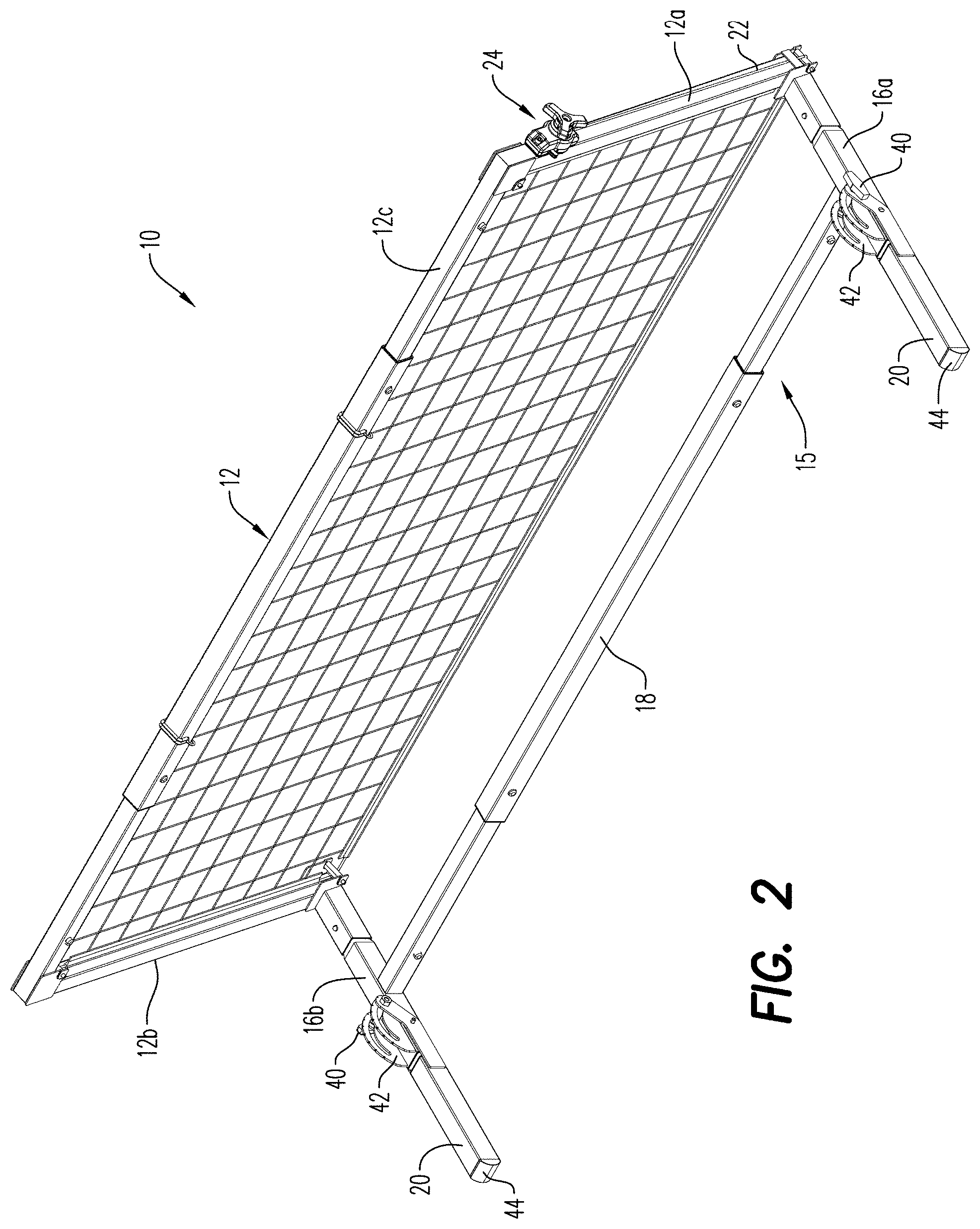
[0011] FIG. 2 is a rear perspective view of the rebounding device of FIG. 1.
[0012] FIG. 3 is a front elevation view of the rebounding device of FIG. 1.
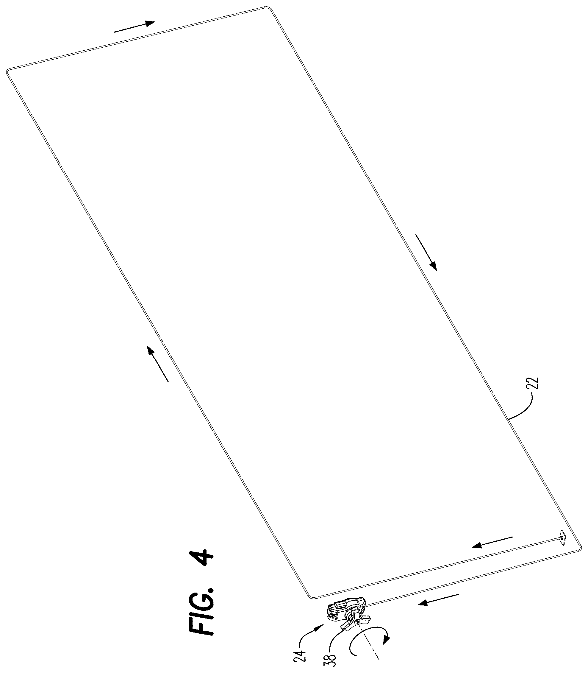
[0013] FIG. 4 is a schematic diagram of the tensioning cable utilized in the rebounding device of FIG. 1.
[0014] FIG. 5 is a schematic diagram of an embodiment of a tensioning mechanism utilized in the rebounding device according to exemplary embodiments of the disclosure.
[0015] FIG. 6 is a side view of the rebounding device of FIG. 1, with the legs being shown in a first position.
[0016] FIG. 7 is a side view of the rebounding device of FIG. 1, with the legs being shown in a second position.
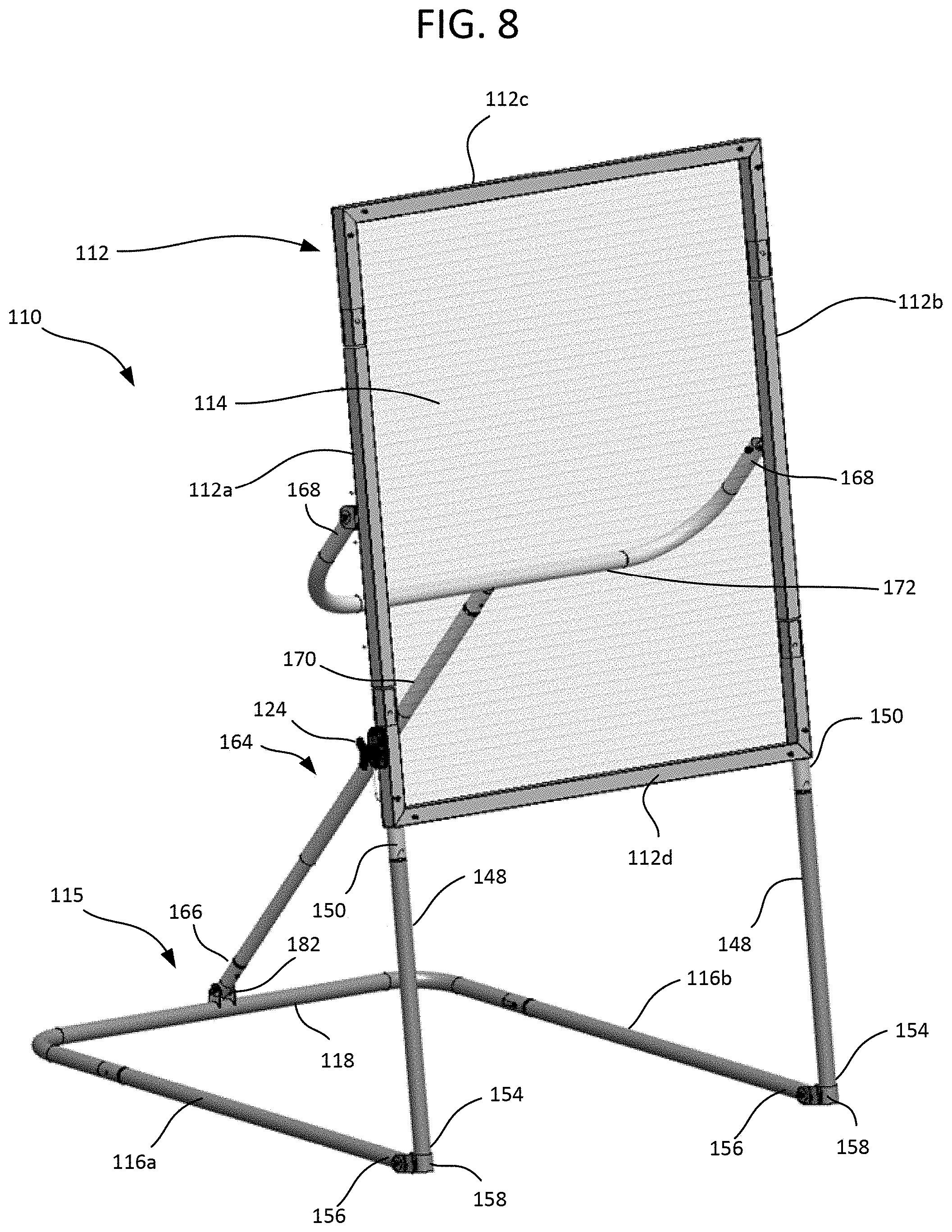
[0017] FIG. 8 is a front perspective view of a rebounding device according to another embodiment of the disclosure.
[0018] FIG. 9 is a partial front perspective view of a coupling between a frame and vertical support members of the rebounding device of FIG. 8.
[0019] FIG. 10 is a partial perspective view of a base of the rebounding device of FIG. 8.
[0020] FIG. 10A illustrates a coupling of a vertical support member and the base of the rebounding device of FIG. 8.
[0021] FIG. 11 is a rear perspective view of the rebounding device of FIG. 8.
[0022] FIG. 11A illustrates a coupling of an angled support member and the base of the rebounding device of FIG. 8.
[0023] FIG. 12 illustrates a coupling of an angled support member and the frame of the rebounding device of FIG. 8.
[0024] FIG. 12A illustrates a coupling of an angled support member and the frame of the rebounding device of FIG. 8.
[0025] FIG. 13 is a partial rear view showing a cable tensioning system of the rebounding device of FIG. 8.
[0026] FIG. 13A illustrates a corner frame and spindle assembly of the cable tensioning system of the rebounding device of FIG. 13.
DETAILED DESCRIPTION
[0027] Referring to FIGS. 1-4, a rebounding device 10 according to an exemplary embodiment of the disclosure is shown. The rebounding device 10 includes a frame 12 with a net 14 extending within the opening of the frame 12. The net 14 is preferably formed from an inelastic mesh netting (e.g. including a polyester, polyethylene, and/or nylon material). In some aspects, other types of materials could be used, such as a netting comprising an elastic material. In still yet other aspects, the net 14 may be a solid piece of a fabric material, for example a woven fabric material, or other suitable material for rebounding of a ball for example. The frame 12 includes opposing side frame members 12a, 12b and an upper frame member 12c which together define a generally rectilinear structure, such as a rectangle or square. It should be noted, however, that other frame shapes (such as curved) may be suitable in some embodiments. The shape and geometry of the frame 12 may be dictated by the sport for which it is intended to train. In some embodiments, the frame 12 has only three frame members 12a, 12b, 12c in that there is no bottom frame member, and it is thus a bottomless frame. Such a bottomless configuration may be particularly suitable for soccer training as omission of a bottom frame member allows a soccer ball to be kicked into the net 14 without hitting the metal tubing of the frame structure. However, a four-sided frame may be suitable with other sports, such as baseball, lacrosse, and field hockey.
[0028] The lower ends of the side frame members 12a, 12b form ground engaging points of contact for the rebounding device 10. Extending rearward from the frame 12 is a base member 15 which provides support for the net 14. According to an exemplary embodiment, the base member 15 includes at least two rearward extending legs 16a, 16b and a support cross member 18 disposed between the legs 16a, 16b. Each of the legs 16a, 16b includes a pivotal foot 20, as discussed further below.
[0029] A cable 22 is disposed around the perimeter of the net 14 and a cable tensioning mechanism 24 is utilized to maintain the net 14 taut within the frame 12. The cable 22 may be a non-elastic material, including a polyester, polyethylene, Kevlar, a metallic and/or a nylon material. In some aspects, however, the cable 22 may be an elastic material or a combination of elastic and non-elastic materials. More particularly, in one embodiment, the frame 12 includes four corner elements 28, each having a front member 28a and a rear member 28b. A corner spindle 26 is disposed between the front members 28a and the rear members 28b. The cable 22 thus extends around the perimeter of the net 14, by either being woven through the mesh of the net 14 or passed through a reinforcing hem of the net 14, and extends around each of the four corner spindles 26. With reference also to FIG. 4, the cable 22 is anchored or otherwise secured at one of the corner elements 28 of the frame 12, and then extends around the perimeter of the net 14 and around the four corner spindles 26. The other end of the cable 22 terminates at a cable tensioning mechanism 24 preferably disposed on a side of the frame 12. As illustrated in FIG. 5, an exemplary embodiment of the cable tensioning mechanism 24 includes a tensioning mechanism 30 having a drum 32, a gear 34, a spring-loaded arm 36, and a handle 38 rotatable connected to the drum 32. In order to tighten the cable 22 and thus tension the net 14 within the frame 12, a user rotates the handle 38 in a clockwise direction which thereby also turns the drum 32. As the drum 32 rotates, it winds the cable 22 up on the drum 32 and thereby tightens the net 14. The gear 34 and the spring-loaded arm 36 lock the drum 32 in place automatically when rotation is stopped. In order to release the tension in the net 14, such as when the rebounding device 10 is being folded for storage or transport, the handle 38 is first rotated clockwise sufficiently to remove the tension from the spring-loaded arm 36, generally only a few millimeters of rotation. A user then applies pressure in the downward direction on the spring-loaded arm 36 so as to release the locking of the gear 34. This in turn allows the handle 38 to spin counter-clockwise, thus releasing all of the tension in the cable tensioning mechanism 24. One or more clips 46, elastic bungee, or other retaining means may also be added to the middle of the net 14 in order to hold the netting up against the frame 12 and prevent the net 14 from sagging in the middle, if necessary, depending upon the overall size of the rebounding device 10.
[0030] The base member 15 includes foldable, rotatable risers or feet 20 which allow the angle of the net 14 to be adjusted. With reference to FIG. 1, the feet 20 are shown in a first position and a second rotated position is shown in broken lines. As shown best in FIG. 6, when the feet 20 are parallel with the legs 16a, 16b, i.e., flat on the ground surface, the net 14 forms an obtuse angle with the ground surface from the direction in which the ball B will be delivered. In such a case, the ball B is rebounded upwardly into the air, as shown in broken lines. Alternatively, as illustrated in FIG. 7, if the feet 20 are pivoted downward such that the feet 20 become the ground engaging member and the legs 16a, 16b are no longer resting on the ground, then the net 14 forms an acute angle with the ground surface from the direction in which the ball B will be delivered. In this instance, the ball B is rebounded back to the ground, as shown in broken lines. The feet 20 may be pivoted by moving a control handle 40 along an arcuate path on the pivot mechanism 42, or any other means which allows the feet 20 to be folded/unfolded or pivoted between a first predetermined position, a second predetermined position, or any angle there between. The base member 15 is preferably weighted by weights 44 so as to prevent the entire rebounding device 10 from tipping over when it is angled forward by the feet 20 as shown in FIG. 7. In some aspects, the feet 20 may not pivot relative to the legs 16a, 16b. In still yet other aspects, the feet 20 and/or the legs 16a, 16b may be oriented to raise a bottom edge of the net 14 and/or the frame 12 off the ground. In such aspects, the pivot mechanism 42 may be positioned in an alternative arrangement relative to the net 14, the feet 20, and/or the legs 16a, 16b, to permit orienting the net 14 at a desired angle when the net 14 and frame 12 are off the ground.
[0031] In a preferred embodiment, the rebounding device 10 may also be collapsible by pushing the side frame members 12a, 12b together, thereby causing upper frame member 12c and support cross member 18 to collapse in a telescoping manner. Upper frame member 12c and support cross member 18 may be fixedly locked in an extended position by pins, dents, clips or other means, which when released allow them to telescopically collapse.
[0032] As indicated above, the rebounding devices described herein may be utilized for other sports, with the particular frame geometry being dictated by the needs of a particular sport. For example, for use as a lacrosse or baseball rebounding device, the rebounding device may include a four-sided frame. Referring to FIGS. 8-13A, a rebounding device 110 with a four-sided frame 112 is illustrated. A net 114 extends within the opening of the frame 112, with the net 114 being preferably formed from an inelastic mesh netting (e.g. including a polyester, polyethylene, and/or nylon material). In some aspects, other types of materials could be used, such as a netting comprising an elastic material. In still yet other aspects, the net 114 may be a solid piece of a fabric material, for example a woven fabric material, or other suitable material for rebounding of a ball, for example. The frame 112 includes opposing side frame members 112a, 112b, an upper frame member 112c, and a lower frame member 112d, which together define a generally rectilinear structure, such as a rectangle or square. It should be noted, however, that other frame shapes (such as curved frames) may be suitable in some embodiments. In some embodiments, the frame 112 has four frame members 112a, 112b, 112c, and 112d to form a closed rectangular frame 112. In some embodiments, the frame 112 may be formed as a single piece, while in other embodiments, the frame 112 may be formed from multiple pieces that are joined together, such as by nesting, spring-biased pin connections, using fasteners, and/or other coupling mechanisms.
[0033] The frame 112 may be coupled with a base member 115, which provides support for the frame 112 and net 114. In some embodiments, the frame 112 is coupled with the base member 115 via one or more vertical members 148 that extend from the frame 112 toward the base member 115 to elevate the frame 112 and net 114 off the ground. In some embodiments, the vertical members 148 may be formed integrally with and/or otherwise permanently coupled with the frame 112. In other embodiments, the vertical members 148 may be removably coupled with the frame 112. For example, as shown in FIG. 9, the frame 112 defines receptacles 150 that are configured to receive ends of the vertical members 148. In some embodiments, the vertical members 148 may be secured within the receptacles 150 using spring loaded pins 152. It will be appreciated that other coupling mechanisms may be used to secure the vertical members 148 with the frame 112.
[0034] The base member 115 may couple with bottom ends 154 of the vertical members 148 and may extend rearward from the frame 112. According to an exemplary embodiment, the base member 115 includes at least two rearward extending legs 116a, 116b and a support cross member 118 disposed between the legs 116a, 116b. While shown with the support cross member 118 positioned at a rear of legs 116a, 116b, it will be appreciated that the support cross member 118 may be disposed at a more medial position of the legs 116a, 116b, similar to the support cross member 18 of rebounding device 10. As illustrated in FIGS. 10 and 10A, front ends 156 of each leg 116a, 116b are coupled with the bottom ends 154 of the vertical members 148. In some embodiments, the front ends 156 may be pivotally coupled with the bottom ends 154, allowing an angle of the frame 112 and net 114 to be adjusted. For example, a bracket 160 may extend around the bottom ends 154 and include arms 158 positioned on either side of and attached to a respective front end 156. Bushings 162 may be positioned between the arms 158 and the front ends 156, allowing the bracket 160 and vertical members 148 to pivot relative to the legs 116a, 116b. In other embodiments different pivoting mechanisms and/or hinges may be used.
[0035] In some embodiments, the rebounding device 110 may further include an angled member 164 that extends between the base member 115 and the frame 112 to maintain the frame 112 at a desired angle, as illustrated in FIGS. 8 and 11. For example, a lower end 166 of the angled member 164 may couple with the support cross member 118 and one or more upper ends 168 of the angled member 164 may couple with the side frame members 112a, 112b. Here, angled member 164 includes a central member 170 that couples with a medial portion of an upper cross member 172, which extends transversely relative to the central member 170 and couples with the side frame members 112a, 112b. Here, upper cross member 172 is generally Y-shaped so as to enable connection with the central member 170 and each of the side frame members 112a, 112b. It will be appreciated that other forms and/or numbers of angled members may be used in some embodiments. For example, angled members on either side of the rebounding device 110 may extend between a leg 116a, 116b and a corresponding side frame member 112a, 112b. In other embodiments, one or more angled members may extend between a medial portion of the support cross member 118 and one or both of the upper frame member 112c and the lower frame member 112d.
[0036] In some embodiments, the angled member 164 may be configured to telescope to enable an angle of the frame 112/net 114 to be adjusted relative to the base member 115. For example, one or more components of the angled member 164 may be extendable to adjust a length of the angled member 164. As illustrated, central member 170 is formed of a first rod 174 that slidingly receives a second rod 176. The first rod 174 defines a number of apertures 178 along a length of the first rod 174, while the second rod 176 includes a spring-loaded pin 180 that is selectively positionable within the apertures 178 to set a length of the angled member 164. To facilitate angle adjustments, the angled member 164 may be pivotally coupled with the base member 115 and/or frame 112. For example, as shown in FIG. 11A, the lower end 166 of the angled member 164 may be coupled with a bracket 182 that extends from a medial portion of the support cross member 118, with one or more bushings 184 positioned between the bracket 182 and the lower end 166 to facilitate rotation at the joint. Similarly, as shown in FIGS. 12 and 12A, upper ends 168 may be coupled with fasteners to brackets 186 that extend from the side frame members 112a, 112b, with one or more bushings 188 positioned between the brackets 186 and the upper ends 168 to facilitate rotation at the joint. To adjust an angle of the net 114, the angled member 164 may be shortened or lengthened by sliding the first rod 174 relative to the second rod 176 while 1) pivoting the vertical members 148 relative to the legs 116a, 116b and 2) pivoting the angled member 164 relative to one or both of the support cross member 118 and the frame 112.
[0037] In some embodiments, the components of frame 112 and/or base member 115 may each be formed as a single piece. In other embodiments, the components may be formed from several pieces that are fixedly or removably joined. In some embodiments, one or more of these components may include additional features. For example, reinforcement members, and/or other features that provide strength, stability, and/or other characteristics to the rebounding device 110 may be included.
[0038] In some embodiments, the various pieces of the base member 115, vertical members 148, and/or angled member 164 may be connected to one another directly. For example, one or more of the base member 115, vertical members 148, and/or angled member 164 may include mating features that are used to secure the pieces of the rebounding device 110 together. In other embodiments, the pieces of the base member 115, vertical members 148, and/or angled member 164 may be secured using one or more fasteners (such as nuts and bolts) and/or may be permanently secured to one another, such as via welding. In other embodiments, the various pieces of the base member 115, vertical members 148, and/or angled member 164 may be connected via one or more joint members that may have mating features that are usable to assemble the frame 102. In some embodiments, the rebounding device 110 may be capable of being disassembled and packed into a smaller form factor for storage and/or transport.
[0039] As shown in FIG. 13, cable 122 is disposed around the perimeter of the net 114 and a cable tensioning mechanism 124 (which may be similar to cable tensioning mechanism 24 described above) is utilized to maintain the net 114 taut within the frame 112. The cable 122 may be a non-elastic material, including a polyester, polyethylene, Kevlar, a metallic and/or a nylon material. In some aspects, however, the cable 122 may be an elastic material or a combination of elastic and non-elastic materials. More particularly and as best seen in FIG. 13A, in one embodiment the frame 112 includes one or more corner spindles 126 extending from the rear surface of the frame 112 proximate the corners of the frame 112. The cable 122 thus extends around the perimeter of the net 114, by either being woven through the mesh of the net 114 or passed through a reinforcing hem of the net 114, and extends around each of the corner spindles 126. In some embodiments, four corner spindles 126 may be used, with each corner spindle 126 centered about a respective corner of the frame 112 to produce a cable path that is generally rectangular as shown in relation to FIGS. 1-4 above. In other embodiments, such as shown in FIG. 13A, two or more corner spindles 126 are positioned at each corner element 128, with the corner spindles 126 being positioned slightly inward from a respective corner of the frame 112 so as to produce a cable path with angled corners. For example, the cable path may be octagonal, with long major sides following the shape of the frame 112 and with minor sides proximate the corners of the frame that are at an angle relative to the major sides. A corner element 128 is mounted and secured on the corner spindles 126 (such as via nuts 129) at each frame corner to ensure that the cable 122 cannot disengage from the corner spindles 126.
[0040] One end of the cable 122 may be anchored or otherwise secured to a corner spindle 126 at one of the corners of the frame 112, and then extends around the perimeter of the net 114 and around the corner spindles 126 in a manner similar to that shown in FIG. 4 above. The other end of the cable 122 terminates at a cable tensioning mechanism 124 preferably disposed on a side of the frame 112. Cable tensioning mechanism 124 may have a similar design and operation as the cable tensioning mechanism 24 described in relation to FIG. 5.
[0041] In some embodiments, the vertical members 148 may be shorter than illustrated in FIGS. 8-13A. This may be particularly useful for practicing certain sport-related activities, such as pitching a baseball or taking a low lacrosse shot that require a player to throw and/or otherwise direct a ball lower to the ground. In some embodiments, the vertical members 148 may be fixed at lower heights, while in other embodiments the vertical members 148 may be configured to telescope and/or otherwise adjust to positions that drop a height of the net 114 to a sufficiently low level to practice such sport maneuvers.
[0042] Although certain exemplary embodiments of the disclosure have been shown and described in detail, it should be understood that various changes and modifications may be made therein without departing from the scope of the appended claims.
* * * * *
D00000
D00001
D00002
D00003
D00004
D00005
D00006
D00007
D00008
D00009
D00010
D00011
D00012

D00013

D00014

D00015

D00016

XML
uspto.report is an independent third-party trademark research tool that is not affiliated, endorsed, or sponsored by the United States Patent and Trademark Office (USPTO) or any other governmental organization. The information provided by uspto.report is based on publicly available data at the time of writing and is intended for informational purposes only.
While we strive to provide accurate and up-to-date information, we do not guarantee the accuracy, completeness, reliability, or suitability of the information displayed on this site. The use of this site is at your own risk. Any reliance you place on such information is therefore strictly at your own risk.
All official trademark data, including owner information, should be verified by visiting the official USPTO website at www.uspto.gov. This site is not intended to replace professional legal advice and should not be used as a substitute for consulting with a legal professional who is knowledgeable about trademark law.