Endoscope Bonding Structure And Endoscope
KAGEYAMA; Naohiro ; et al.
U.S. patent application number 17/098770 was filed with the patent office on 2021-03-04 for endoscope bonding structure and endoscope. This patent application is currently assigned to OLYMPUS CORPORATION. The applicant listed for this patent is OLYMPUS CORPORATION. Invention is credited to Takaharu FUJII, Naohiro KAGEYAMA.
| Application Number | 20210059505 17/098770 |
| Document ID | / |
| Family ID | 1000005260467 |
| Filed Date | 2021-03-04 |


| United States Patent Application | 20210059505 |
| Kind Code | A1 |
| KAGEYAMA; Naohiro ; et al. | March 4, 2021 |
ENDOSCOPE BONDING STRUCTURE AND ENDOSCOPE
Abstract
An endoscope bonding structure includes a distal end rigid member, a tubular body, and a bonding agent. The distal end rigid member includes a first outer diameter part and a second outer diameter part. The tubular body includes a first inner diameter part and a second inner diameter part. An outer diameter of an outer periphery of the second outer diameter part decreases as a distance increases toward a proximal end side. The tubular body is fitted to an outer periphery in a state in which the tubular body is pressed to a distal end side.
| Inventors: | KAGEYAMA; Naohiro; (Tokyo, JP) ; FUJII; Takaharu; (Tokyo, JP) | ||||||||||
| Applicant: |
|
||||||||||
|---|---|---|---|---|---|---|---|---|---|---|---|
| Assignee: | OLYMPUS CORPORATION Tokyo JP |
||||||||||
| Family ID: | 1000005260467 | ||||||||||
| Appl. No.: | 17/098770 | ||||||||||
| Filed: | November 16, 2020 |
Related U.S. Patent Documents
| Application Number | Filing Date | Patent Number | ||
|---|---|---|---|---|
| PCT/JP2019/005079 | Feb 13, 2019 | |||
| 17098770 | ||||
| Current U.S. Class: | 1/1 |
| Current CPC Class: | G02B 23/2423 20130101; A61B 1/0011 20130101; A61B 1/0008 20130101 |
| International Class: | A61B 1/00 20060101 A61B001/00; G02B 23/24 20060101 G02B023/24 |
Foreign Application Data
| Date | Code | Application Number |
|---|---|---|
| Jun 6, 2018 | JP | 2018-108492 |
Claims
1. An endoscope bonding structure comprising: a shaft extending in a longitudinal direction; a tubular body fitted to an outer periphery of the shaft in the longitudinal direction in a loosely-fitted state; and a bonding agent filling a gap between the outer periphery of the shaft and an inner periphery of the tubular body, wherein the shaft includes a first outer diameter part formed at a first position on the outer periphery, and a second outer diameter part that is formed at a second position on the outer periphery, is smaller than the first outer diameter part, and has a first length in the longitudinal direction, the tubular body includes a first inner diameter part formed on one side of the inner periphery of the tubular body in the longitudinal direction, the first inner diameter part having a diameter larger than a diameter of the first outer diameter part, the first inner diameter part having a second length equal to or longer than the first length in the longitudinal direction, and a second inner diameter part formed continuously with the first inner diameter part on another side of the inner periphery of the tubular body in the longitudinal direction, the second inner diameter having a diameter smaller than the diameter of the first inner diameter part, the second outer diameter part is formed so that an outer diameter of the outer periphery decreases as a distance increases in a direction opposite to the first outer diameter part, and the tubular body is fitted to the outer periphery of the shaft in a state in which the tubular body is pressed to the one side so that the first inner diameter part side moves toward the first position through the second position.
2. The endoscope bonding structure according to claim 1, wherein the first position and the second position are provided in the longitudinal direction, and the second outer diameter part is formed so that the outer diameter of the outer periphery decreases gradually as a distance increases toward the other side opposite to the first outer diameter part in the longitudinal direction.
3. The endoscope bonding structure according to claim 1, wherein the first position and the second position are provided in the longitudinal direction, and the second outer diameter part is formed so that the outer diameter of the outer periphery decreases in a stepwise manner as a distance increases toward the other side opposite to the first outer diameter part in the longitudinal direction.
4. The endoscope bonding structure according to claim 1, wherein the second inner diameter part is configured as a ring that is freely movable on the inner periphery of the tubular body in the longitudinal direction, and the ring is pressed to the one side in the longitudinal direction by an urging member.
5. The endoscope bonding structure according to claim 1, wherein the first outer diameter part of the shaft is provided with a blockage member that blocks an opening of the first inner diameter part of the tubular body on the one side.
6. An endoscope comprising: a distal end member extending in a longitudinal direction; a tubular body fitted to an outer periphery of the distal end member in the longitudinal direction in a loosely-fitted state; and a bonding agent filling a gap between the outer periphery of the distal end member and an inner periphery of the tubular body, wherein the distal end member includes a first outer diameter part formed at a first position on the outer periphery, and a second outer diameter part that is formed at a second position on the outer periphery, is smaller than the first outer diameter part, and has a first length in the longitudinal direction, the tubular body includes a first inner diameter part formed on a distal end side of the inner periphery of the tubular body in the longitudinal direction, the first inner diameter part having a diameter larger than a diameter of the first outer diameter part, the first inner diameter part having a second length equal to or longer than the first length in the longitudinal direction, and a second inner diameter part formed continuously with the first inner diameter part on a proximal end side of the inner periphery of the tubular body in the longitudinal direction, the second inner diameter having a diameter smaller than the diameter of the first inner diameter part, the second outer diameter part is formed so that an outer diameter of the outer periphery decreases as a distance increases in a direction opposite to the first outer diameter part, and the tubular body is fitted to the outer periphery of the distal end member in a state in which the tubular body is pressed to the distal end side so that the first inner diameter part side moves toward the first position through the second position.
Description
CROSS REFERENCE TO RELATED APPLICATION
[0001] This application is a continuation application of PCT/JP2019/005079 filed on Feb. 13, 2019 and claims benefit of Japanese Application No. 2018-108492 filed in Japan on Jun. 6, 2018, the entire contents of which are incorporated herein by this reference.
BACKGROUND OF THE INVENTION
1. Field of the Invention
[0002] The present invention relates to an endoscope bonding structure and an endoscope in each of which a tubular body is bonded and fitted to an outer periphery of a shaft.
2. Description of the Related Art
[0003] Recently, endoscopes have been widely used in a medical field and an industrial field. With an endoscope used in the medical field, an organ in a body cavity as a subject can be observed through an elongated insertion portion inserted into the body cavity, and various kinds of treatment can be performed as necessary by using a treatment instrument inserted into a treatment instrument insertion channel included in the endoscope.
[0004] With an endoscope used in the industrial field, observation and examination involving various treatments can be performed on flaw, corrosion, and the like of a site to be examined in an object such as a jet engine or a pipe at a factory through an elongated insertion portion of the endoscope inserted into the object.
[0005] Known endoscopes include what is called a flexible endoscope including a flexible insertion portion and what is called a rigid endoscope including a rigid insertion portion.
[0006] In a known configuration of the insertion portion of the rigid endoscope, a distal end rigid member that is a shaft is bonded and fixed to a distal end of a tubular body in a longitudinal direction.
[0007] For example, a distal end of a known light guide in the longitudinal direction, or a distal end of a relay lens provided in an image pickup unit or insertion portion including an objective lens unit in the longitudinal direction is fixed to the distal end rigid member.
[0008] Specifically, the distal end rigid member is configured by a fitting site that is fitted into the tubular body through a distal end opening of the tubular body in the longitudinal direction, and a blockage member that blocks the distal end opening of the tubular body.
[0009] The distal end rigid member is bonded and fixed to the tubular body by a bonding agent filling a gap between an outer periphery of the fitting site and an inner periphery of the tubular body and a bonding agent filling a gap between a distal end of the tubular body in the longitudinal direction and a site of the blockage member opposing to the distal end of the tubular body in the longitudinal direction.
[0010] In the bonding and fixation of the distal end rigid member to the tubular body, a method is employed in which the distal end side of the tubular body in the longitudinal direction is fitted to the outer periphery of the fitting site in a state in which a bonding agent is applied to the outer periphery of the fitting site.
[0011] Japanese Patent Application Laid-Open Publication No. 2011-200397 discloses a configuration in which a stepped part is provided to the outer periphery of the fitting site of the distal end rigid member to have a diameter that decreases in a stepwise manner as a distance increases toward a back side in the longitudinal direction, and a circumferential step for pressing a bonding agent is provided to the inner periphery of the tubular body on the distal end side in the longitudinal direction.
SUMMARY OF THE INVENTION
[0012] An endoscope bonding structure according to an aspect of the present invention is an endoscope bonding structure including: a shaft extending in a longitudinal direction; a tubular body fitted to an outer periphery of the shaft in the longitudinal direction in a loosely-fitted state; and a bonding agent filling a gap between the outer periphery of the shaft and an inner periphery of the tubular body. The shaft includes a first outer diameter part formed at a first position on the outer periphery, and a second outer diameter part that is formed at a second position on the outer periphery, is smaller than the first outer diameter part, and has a first length in the longitudinal direction. The tubular body includes a first inner diameter part formed on one side of the inner periphery of the tubular body in the longitudinal direction, the first inner diameter part having a diameter larger than a diameter of the first outer diameter part, the first inner diameter part having a second length equal to or longer than the first length in the longitudinal direction, and a second inner diameter part formed continuously with the first inner diameter part on another side of the inner periphery of the tubular body in the longitudinal direction, the second inner diameter having a diameter smaller than the diameter of the first inner diameter part. The second outer diameter part is formed so that an outer diameter of the outer periphery decreases as a distance increases in a direction opposite to the first outer diameter part. The tubular body is fitted to the outer periphery of the shaft in a state in which the tubular body is pressed to the one side so that the first inner diameter part side moves toward the first position through the second position.
[0013] An endoscope according to another aspect of the present invention is an endoscope including: a distal end member extending in a longitudinal direction; a tubular body fitted to an outer periphery of the distal end member in the longitudinal direction in a loosely-fitted state; and a bonding agent filling a gap between the outer periphery of the distal end member and an inner periphery of the tubular body. The distal end member includes a first outer diameter part formed at a first position on the outer periphery, and a second outer diameter part that is formed at a second position on the outer periphery, is smaller than the first outer diameter part, and has a first length in the longitudinal direction. The tubular body includes a first inner diameter part formed on a distal end side of the inner periphery of the tubular body in the longitudinal direction, the first inner diameter part having a diameter larger than a diameter of the first outer diameter part, the first inner diameter part having a second length equal to or longer than the first length in the longitudinal direction, and a second inner diameter part formed continuously with the first inner diameter part on a proximal end side of the inner periphery of the tubular body in the longitudinal direction, the second inner diameter having a diameter smaller than the diameter of the first inner diameter part. The second outer diameter part is formed so that an outer diameter of the outer periphery decreases as a distance increases in a direction opposite to the first outer diameter part. The tubular body is fitted to the outer periphery of the distal end member in a state in which the tubular body is pressed to the distal end side so that the first inner diameter part side moves toward the first position through the second position.
BRIEF DESCRIPTION OF THE DRAWINGS
[0014] FIG. 1 is a perspective view schematically illustrating a configuration of an endoscope including a bonding structure of a first embodiment;
[0015] FIG. 2 is a partial cross-sectional view schematically illustrating a bonding structure of a site surrounded by line II at a distal end portion in FIG. 1;
[0016] FIG. 3 is a partial cross-sectional view illustrating a halfway process in which a tubular body is fitted to an outer periphery of a fitting portion of a distal end rigid member in FIG. 2 in an assembly process;
[0017] FIG. 4 is a partial cross-sectional view illustrating a modification of an outer peripheral shape of the fitting portion of the distal end rigid member in FIG. 2;
[0018] FIG. 5 is a partial cross-sectional view schematically illustrating an endoscope bonding structure of a second embodiment;
[0019] FIG. 6 is a partial cross-sectional view schematically illustrating an endoscope bonding structure of a third embodiment;
[0020] FIG. 7 is a cross-sectional view of the distal end rigid member taken along line in FIG. 6;
[0021] FIG. 8 is a cross-sectional view of the tubular body taken along line VIII-VIII in FIG. 6;
[0022] FIG. 9 is a partial cross-sectional view schematically illustrating an endoscope bonding structure of a fourth embodiment;
[0023] FIG. 10 is a cross-sectional view of the distal end rigid member taken along line X-X in FIG. 9; and
[0024] FIG. 11 is a cross-sectional view of the tubular body taken along line XI-XI in FIG. 9.
DETAILED DESCRIPTION OF THE PREFERRED EMBODIMENTS
[0025] Embodiments of the present invention will be described below with reference to the accompanying drawings. Note that the drawings are schematic, for example, relations among thicknesses and widths of members and ratios of the thicknesses of the members are different from the relations and ratios in reality, and the drawings include parts, relations and ratios of dimensions of which are different among the drawings.
First Embodiment
[0026] FIG. 1 is a perspective view schematically illustrating a configuration of an endoscope having a bonding structure of the present embodiment.
[0027] As illustrated in FIG. 1, the endoscope 1 is configured by including, as main parts, an insertion portion 2 that is elongated and inserted into a subject, an operation portion 4, a universal cable 30, and a connector 32.
[0028] The insertion portion 2 is configured by including, as main parts sequentially from a distal end side in a longitudinal direction N, a distal end portion 10, a bending portion 12 that is freely bendable in a plurality of directions, and a pipe portion 14 that is elongated in the longitudinal direction N of the insertion portion 2 and rigid. Accordingly, the endoscope 1 in the present embodiment is configured as a rigid endoscope including the insertion portion 2 that is hard.
[0029] The operation portion 4 is provided continuously with a proximal end of the pipe portion 14 in the longitudinal direction N. The operation portion 4 is provided with an operation lever 18 that is freely rotatable and performs a bending operation of the bending portion 12 in an up-down direction, and an operation lever 20 that is freely rotatable and performs a bending operation of the bending portion 12 in a right-left direction.
[0030] The operation portion 4 is also provided with a fixation lever 22 that fixes a rotational position of the operation lever 18. Note that although not illustrated, the operation portion 4 is also provided with another fixation lever that fixes a rotational position of the operation lever 20.
[0031] In addition, the operation portion 4 includes a grip 24 that is grasped by an operator, and the grip 24 is provided with a remote switch 26. The remote switch 26 remotely operates various instruments connected with the connector 32.
[0032] The universal cable 30 is extended from the operation portion 4 and provided with the connector 32 at an extension end.
[0033] A connection end part 32a of a nonillustrated light guide is provided as an extension to the connector 32. A camera cable 34 is extended from the connector 32.
[0034] A camera connector 36 is provided at an extension end of the camera cable 34. The camera connector 36 is connected with a nonillustrated camera control unit that performs signal processing of an optical image of inside of the subject, which is picked up by a nonillustrated image pickup unit. Note that the camera control unit is connected with a monitor that performs image display of an optical image, a video recording device, or the like, which are all not illustrated.
[0035] In addition, a ventilation pipe sleeve 38 is provided to the connector 32. The endoscope 1 normally has a watertight structure, but when the ventilation pipe sleeve 38 is opened, inside of the endoscope 1 communicates with outside. Thus, with the ventilation pipe sleeve 38, it is possible to select a state of communication between the inside and outside of the endoscope 1 and to examine water leakage of the endoscope 1.
[0036] Subsequently, a bonding structure of the distal end portion in FIG. 1 will be described with reference to FIGS. 2 and 3. FIG. 2 is a partial cross-sectional view schematically illustrating a bonding structure of a site surrounded by line II at the distal end portion in FIG. 1, and FIG. 3 is a partial cross-sectional view illustrating a halfway process in which a tubular body is fitted to an outer periphery of a fitting portion of a distal end rigid member in FIG. 2 in an assembly process.
[0037] As illustrated in FIGS. 2 and 3, the distal end portion 10 is configured such that a tubular body 60 that configures an exterior of the distal end portion 10 is bonded and fixed to a distal end rigid member 50 that is a shaft.
[0038] Note that a distal end of the light guide in the longitudinal direction N, which is inserted into the insertion portion 2, the operation portion 4, the universal cable 30, and the connector 32, which are not illustrated, a nonillustrated image pickup unit including an objective lens unit provided in the distal end portion 10, and the like are fixed to the distal end rigid member 50.
[0039] The distal end rigid member 50 and the tubular body 60 may be each made of metal or may be each made of resin that can be subjected to known autoclave sterilization processing.
[0040] The distal end rigid member 50 is configured by including a fitting portion 51 and a blockage member 52 as main parts.
[0041] The fitting portion 51 includes a first outer diameter part 51a formed at a first position on an outer periphery 51g and having an outer diameter K1, and a second outer diameter part 51b that is formed at a second position on the outer periphery 51g and is smaller than the first outer diameter part 51a.
[0042] Note that the first position and the second position on the outer periphery 51g are provided in a longitudinal direction N of the distal end rigid member 50, which is aligned with the longitudinal direction N of the insertion portion 2, and the first position is positioned on a distal end side N1 that is one side of the second position in the longitudinal direction N.
[0043] The second outer diameter part 51b has a first length A in the longitudinal direction N. The second outer diameter part 51b is formed to have a diameter smaller than the diameter of the first outer diameter part 51a.
[0044] Specifically, the second outer diameter part 51b is formed so that an outer diameter of the outer periphery 51g decreases gradually as a distance increases toward a proximal end side N2 that is the other side opposite to the first outer diameter part 51a in the longitudinal direction N. In other words, the outer periphery 51g of the second outer diameter part 51b is formed as a tilted surface of a diameter that decreases gradually as a distance increases toward the proximal end side N2 in the longitudinal direction N.
[0045] A distal end of the first outer diameter part 51a of the fitting portion 51 in the longitudinal direction N is provided with the blockage member 52 that blocks an opening 61a of a first inner diameter part 61 of the tubular body 60 on the distal end side N1, which will be described later, when the tubular body 60 is fitted to the outer periphery 51g of the distal end rigid member 50.
[0046] Note that the blockage member 52 has a diameter that is larger than the diameter of the first outer diameter part 51a and substantially equal to a diameter of the tubular body 60.
[0047] The tubular body 60 is fitted to the outer periphery 51g of the fitting portion 51 of the distal end rigid member 50 in the longitudinal direction N in a loosely-fitted state, and includes the first inner diameter part 61 and a second inner diameter part 62.
[0048] The first inner diameter part 61 is formed on the distal end side N1 of an inner periphery 60n of the tubular body 60, has a diameter larger than the diameter of the first outer diameter part 51a (K3>K1), and has a second length B equal to or longer than the first length A (B.gtoreq.A) in the longitudinal direction N. Note that the second length B is set to be equal to or shorter than a length of the fitting portion 51.
[0049] The second inner diameter part 62 is formed continuously with the first inner diameter part 61 on the proximal end side N2 of the inner periphery 60n of the tubular body 60 and has a diameter smaller than the diameter of the first inner diameter part 61 (K4<K3).
[0050] Accordingly, since the second inner diameter part 62 is formed to have a diameter smaller than the diameter of the first inner diameter part 61, a step 65 is circumferentially formed between the first inner diameter part 61 and the second inner diameter part 62 in the longitudinal direction N on the inner periphery 60n of the tubular body 60.
[0051] A bonding agent 70 fills a gap between the outer periphery 51g of the fitting portion 51 of the distal end rigid member 50 and the inner periphery 60n of the tubular body 60. The tubular body 60 is bonded and fixed to the outer periphery 51g by the bonding agent 70.
[0052] Specifically, in a state in which the first outer diameter part 51a and the second outer diameter part 51b are covered by the first inner diameter part 61 as illustrated in FIG. 2, the tubular body 60 is bonded and fixed to the outer periphery 51g by the bonding agent 70 filling a gap between the outer periphery 51g and an inner periphery of the first inner diameter part 61 and a gap between a surface 52t of the blockage member 52 on the proximal end side N2 in the longitudinal direction N and a distal end surface 61s of the first inner diameter part 61 on the distal end side N1 in the longitudinal direction N.
[0053] Note that, at fitting to the outer periphery 51g of the fitting portion 51, the tubular body 60 is fitted to the outer periphery 51g of the fitting portion 51 as the tubular body 60 is pressed to the distal end side N1 in the longitudinal direction N so that the first inner diameter part 61 side, in other words, the opening 61a side moves toward the first position through the second position on the outer periphery 51g in a state in which the bonding agent 70 is circumferentially and uniformly applied to the outer periphery 51g.
[0054] In the pressing, the bonding agent 70 applied to the outer periphery 51g is pressed to the distal end side N1 in a state in which pressing pressure toward the distal end side N1 is increased by the step 65.
[0055] As described above, the second outer diameter part 51b of the outer periphery 51g is formed to have an outer diameter that decreases gradually as a distance increases toward the proximal end side N2.
[0056] In addition, the first inner diameter part 61 has the second length B equal to or longer than the first length A of the second outer diameter part 51b (B.gtoreq.A) in the longitudinal direction N and is set to be equal to or shorter than the length of the fitting portion 51.
[0057] Accordingly, a large space W is formed between the first inner diameter part 61 and the second outer diameter part 51b in the longitudinal direction N, and thus at pressing, the bonding agent 70 stays in a gap between the surface 52t of the blockage member 52 and the distal end surface 61s of the first inner diameter part 61 but hardly leaks to outside from the gap, and then flows to the proximal end side N2 along the outer periphery 51g in the space W. As a result, the bonding agent 70 uniformly remains on the outer periphery 51g.
[0058] In this manner, it is possible to provide the bonding structure of the endoscope 1, and the endoscope 1, each having a configuration in which the bonding agent 70 uniformly remains on the outer periphery 51g without leakage in a state in which the tubular body 60 is fitted to the outer periphery 51g of the fitting portion 51 of the distal end rigid member 50.
[0059] Note that a modification will be illustrated with reference to FIG. 4. FIG. 4 is a partial cross-sectional view illustrating a modification of an outer peripheral shape of the fitting portion of the distal end rigid member in FIG. 2.
[0060] In the present embodiment described above, the second outer diameter part 51b is formed so that the outer diameter of the outer periphery 51g decreases gradually as a distance increases toward the proximal end side N2. Specifically, it is described that the outer periphery 51g of the second outer diameter part 51b is formed as a tilted surface of a diameter that decreases gradually as a distance increases toward the proximal end side N2.
[0061] The present embodiment is not limited to this configuration, but it is possible to obtain effects same as effects of the present embodiment described above even when the second outer diameter part 51b is formed so that the outer diameter of the outer periphery 51g decreases in a stepwise manner as a distance increases toward the proximal end side N2 as illustrated in FIG. 4.
Second Embodiment
[0062] FIG. 5 is a partial cross-sectional view schematically illustrating an endoscope bonding structure of the present embodiment.
[0063] An endoscope bonding structure and an endoscope of the second embodiment are different from the above-described endoscope bonding structure of the first embodiment illustrated in FIGS. 1 to 3 in that the second inner diameter part of the tubular body is configured as a ring that is freely movable in the longitudinal direction, and the ring is pressed to the distal end side in the longitudinal direction by an urging member.
[0064] Thus, only this difference will be described below, components which are the same as components of the first embodiment will be denoted by the same reference signs, and description of such components will be omitted.
[0065] As illustrated in FIG. 5, in the present embodiment, the second inner diameter part 62 is configured as a ring 62d that is freely movable on the inner periphery 60n of the tubular body 60 in the longitudinal direction N.
[0066] The ring 62d is pressed to the distal end side N1 by a compression spring (hereinafter simply referred to as a spring) 80 that is an urging member.
[0067] Note that the spring 80 is fixed to the inner periphery 60n on the proximal end side N2 and fixed to the ring 62d on the distal end side N1. A strength of pressing to the distal end side N1 by the ring 62d can be freely set by changing a strength of the spring 80.
[0068] Note that the other configuration is same as the configuration of the first embodiment described above.
[0069] With such a configuration, the step 65 formed by the ring 62d reliably presses the bonding agent 70 applied to the outer periphery 51g to the distal end side N1 through urging by the spring 80.
[0070] Thus, even when a bonding agent having a higher viscosity is used as the bonding agent 70, the bonding agent can be more reliably pressed and stretched to the distal end side N1 than in the first embodiment described above.
[0071] Accordingly, the bonding agent 70 having a high viscosity can be caused to uniformly remain on the outer periphery 51g without leakage. Note that the other effects are same as the effects of the first embodiment described above.
Third Embodiment
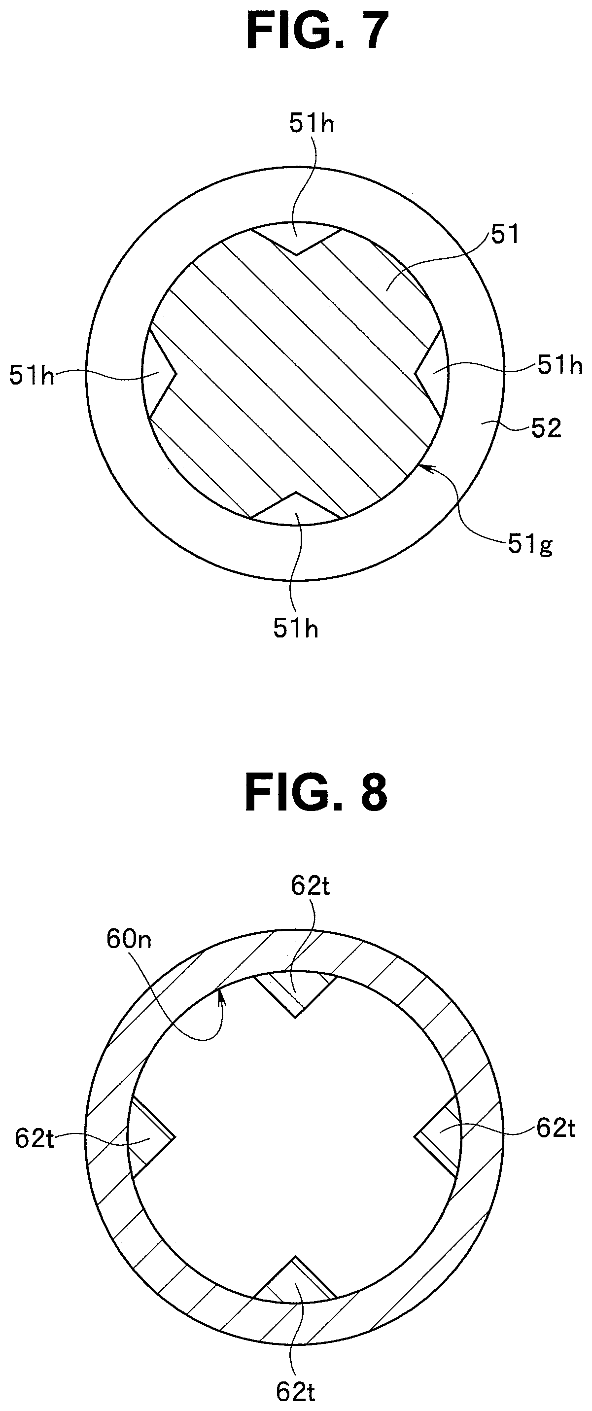
[0072] FIG. 6 is a partial cross-sectional view schematically illustrating an endoscope bonding structure of the present embodiment, FIG. 7 is a cross-sectional view of the distal end rigid member taken along line VII-VII in FIG. 6, and FIG. 8 is a cross-sectional view of the tubular body taken along line VIII-VIII in FIG. 6.
[0073] An endoscope bonding structure and an endoscope of the third embodiment are different from the above-described endoscope bonding structure of the first embodiment illustrated in FIGS. 1 to 3 in that a groove to which protrusions provided on the inner periphery of the tubular body is fitted are formed in the longitudinal direction at the outer periphery of the fitting portion of the distal end rigid member.
[0074] Thus, only this difference will be described below, components which are the same as components of the first embodiment will be denoted by the same reference signs, and description of such components will be omitted.
[0075] As illustrated in FIG. 6, the distal end portion 10 is configured such that the tubular body 60 that configures the exterior of the distal end portion 10 is bonded and fixed to the distal end rigid member 50 that is the shaft.
[0076] Note that the distal end of the light guide in the longitudinal direction N, which is inserted into the insertion portion 2, the operation portion 4, the universal cable 30, and the connector 32, which are not illustrated, the nonillustrated image pickup unit including the objective lens unit provided in the distal end portion 10, and the like are fixed to the distal end rigid member 50.
[0077] The distal end rigid member 50 and the tubular body 60 may be made of metal or may be made of resin that can be subjected to known autoclave sterilization processing.
[0078] The distal end rigid member 50 is configured by including the fitting portion 51 and the blockage member 52 as main parts.
[0079] The fitting portion 51 is formed to have a predetermined length in the longitudinal direction N so that the outer periphery 51g has a constant diameter.
[0080] A groove 51h is formed at the outer periphery 51g of the fitting portion 51, for example, at every 90.degree. in the longitudinal direction N.
[0081] The bonding agent 70 applied to the outer periphery 51g is fitted to each groove 51h, and in addition, a protrusion 62t to be described later is fitted to the groove 51h when the tubular body 60 is fitted to the outer periphery 51g of the fitting portion 51.
[0082] Note that a section of each groove 51h has, for example, a triangular shape in FIG. 7, but may have any other sectional shape. Moreover, the number of grooves 51h is not limited to four.
[0083] A distal end of the fitting portion 51 in the longitudinal direction N is provided with the blockage member 52 that blocks the opening 61a of the first inner diameter part 61 of the tubular body 60 on the distal end side N1, which will be described later, when the tubular body 60 is fitted to the outer periphery 51g of the fitting portion 51. Note that the blockage member 52 has a diameter larger than a diameter of the fitting portion 51 and substantially equal to the diameter of the tubular body 60.
[0084] The tubular body 60 is fitted to the outer periphery 51g of the fitting portion 51 of the distal end rigid member 50 in the longitudinal direction N in the loosely-fitted state, and includes the first inner diameter part 61 and the second inner diameter part 62.
[0085] The first inner diameter part 61 is formed on the distal end side N1 of the inner periphery 60n of the tubular body 60 and has a diameter larger than the diameter of the fitting portion (K3>K1).
[0086] As illustrated in FIG. 8, the second inner diameter part 62 is formed continuously with the first inner diameter part 61 on the proximal end side N2 of the inner periphery 60n of the tubular body 60, has a diameter smaller than the diameter of the first inner diameter part 61 (K4<K3), and is configured of the protrusion 62t formed on the inner periphery 60n, for example, at every 45.degree. in the longitudinal direction N.
[0087] Each protrusion 62t is fitted to the corresponding groove 51h when the tubular body 60 is fitted to the outer periphery 51g of the fitting portion 51.
[0088] Note that the section of each protrusion 62t has, for example, a triangular shape in FIG. 8, but may have any other sectional shape. Moreover, the number of protrusions 62t is not limited to four.
[0089] Accordingly, the step 65 is formed for each protrusion 62t on the inner periphery 60n of the tubular body 60 since the second inner diameter part 62 is formed between the first inner diameter part 61 and the second inner diameter part 62 in the longitudinal direction N to have a diameter smaller than the diameter of the first inner diameter part 61.
[0090] The bonding agent 70 fills the gap between the outer periphery 51g of the fitting portion 51 of the distal end rigid member 50 and the inner periphery 60n of the tubular body 60. The tubular body 60 is bonded and fixed to the outer periphery 51g by the bonding agent 70.
[0091] Specifically, in a state in which the fitting portion 51 is covered by the first inner diameter part 61 as illustrated in FIG. 6, the tubular body 60 is bonded and fixed to the outer periphery 51g by the bonding agent 70 filling the gap between the outer periphery 51g and the inner periphery of the first inner diameter part 61 and the gap between the surface 52t of the blockage member 52 on the proximal end side N2 in the longitudinal direction N and the distal end surface 61s of the first inner diameter part 61 on the distal end side N1 in the longitudinal direction N.
[0092] Note that, at fitting to the outer periphery 51g of the fitting portion 51 of the distal end rigid member 50, the tubular body 60 is fitted to the outer periphery 51g of the distal end rigid member 50 as the first inner diameter part 61 side, in other words, the opening 61a side is pressed to the distal end side N1 in the longitudinal direction N in a state in which the bonding agent 70 is applied to each groove 51h.
[0093] In the pressing, the bonding agent 70 applied to each groove 51h is pressed to the distal end side N1 in a state in which the pressing pressure is increased by the step 65.
[0094] Along with the pressing, the bonding agent 70 in each groove 51h is pressed in a direction toward the outer periphery 51g of the fitting portion 51.
[0095] Accordingly, at pressing of the tubular body 60, the bonding agent 70 stays in the gap between the surface 52t of the blockage member 52 and the distal end surface 61s of the first inner diameter part 61 but hardly leaks to the outside from the gap, and then flows in the direction toward the outer periphery 51g. As a result, the bonding agent 70 uniformly remains on the outer periphery 51g.
[0096] In this manner, it is possible to provide the bonding structure of the endoscope 1 having a configuration in which the bonding agent 70 uniformly remains on the outer periphery 51g without leakage in a state in which the tubular body 60 is fitted to the outer periphery 51g of the fitting portion 51 of the distal end rigid member 50.
[0097] Note that the above-described second embodiment is also applicable to the present embodiment. Specifically, each protrusion 62t that is freely movable on the inner periphery 60n in the longitudinal direction N may be pressed to the distal end side N1 by using a spring.
Fourth Embodiment
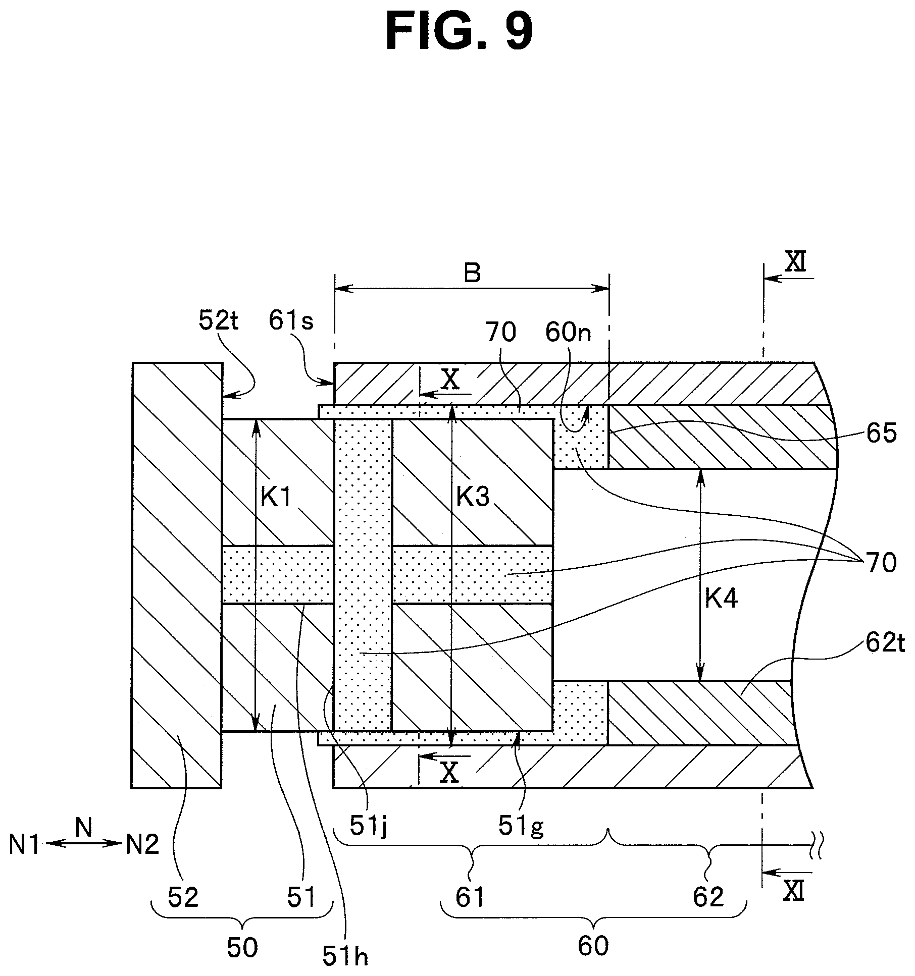
[0098] FIG. 9 is a partial cross-sectional view schematically illustrating an endoscope bonding structure of the present embodiment, FIG. 10 is a cross-sectional view of the distal end rigid member taken along line X-X in FIG. 9, and FIG. 11 is a cross-sectional view of the tubular body taken along line XI-XI in FIG. 9.
[0099] An endoscope bonding structure and an endoscope of the fourth embodiment are different from the above-described endoscope bonding structure of the third embodiment illustrated in FIGS. 6 to 8 in that grooves to which protrusions provided on the inner periphery of the tubular body are fitted are formed in an outer peripheral direction in addition to the longitudinal direction at the outer periphery of the fitting portion of the distal end rigid member.
[0100] Thus, only this difference will be described below, components which are the same as components of the third embodiment will be denoted by the same reference signs, and description of such components will be omitted.
[0101] As illustrated in FIG. 9, the groove 51h is formed at the outer periphery 51g of the fitting portion 51, for example, at every 90.degree. in the longitudinal direction N, and a circumferential groove 51j is formed in a direction along the outer periphery 51g to connect the grooves 51h in the direction along the outer periphery 51g.
[0102] Note that the section of each groove 51h has, for example, a rectangular shape in FIG. 10, but may be any other sectional shape. Moreover, the number of grooves 51h is not limited to four.
[0103] As illustrated in FIG. 11, the second inner diameter part 62 includes the protrusion 62t formed in the longitudinal direction N, for example, at every 90.degree. at the inner periphery 60n.
[0104] Each protrusion 62t is fitted to the corresponding groove 51h when the tubular body 60 is fitted to the outer periphery 51g of the fitting portion 51.
[0105] Note that the section of each protrusion 62t has, for example, a rectangular shape in FIG. 11, but may be any other sectional shape. Moreover, the number of protrusions 62t is not limited to four.
[0106] The bonding agent 70 fills the gap between the outer periphery 51g of the fitting portion 51 of the distal end rigid member 50 and the inner periphery 60n of the tubular body 60. The tubular body 60 is bonded and fixed to the outer periphery 51g by the bonding agent 70.
[0107] Specifically, the tubular body 60 is bonded and fixed to the outer periphery 51g by the bonding agent 70 filling the gap between the outer periphery 51g and the inner periphery of the first inner diameter part 61 and the gap between the surface 52t of the blockage member 52 on the proximal end side N2 in the longitudinal direction N and the distal end surface 61s of the first inner diameter part 61 on the distal end side N1 in a state in which the fitting portion 51 is covered by the first inner diameter part 61 as illustrated in FIG. 9.
[0108] Note that, at fitting to the outer periphery 51g of the fitting portion 51 of the distal end rigid member 50, the tubular body 60 is fitted to the outer periphery 51g of the distal end rigid member 50 as the first inner diameter part 61 side, in other words, the opening 61a side is pressed to the distal end side N1 in the longitudinal direction N in a state in which the bonding agent 70 is applied to each groove 51h.
[0109] In the pressing, the bonding agent 70 applied to each groove 51h is pressed to the distal end side N1 in a state in which the pressing pressure is increased by the step 65.
[0110] Along with the pressing, the bonding agent 70 in each groove 51h is pressed in the direction toward the outer periphery 51g of the fitting portion 51.
[0111] Accordingly, at pressing of the tubular body 60, the bonding agent 70 stays in the gap between the surface 52t of the blockage member 52 and the distal end surface 61s of the first inner diameter part 61 but hardly leaks to the outside from the gap, and then flows in the direction toward the outer periphery 51g while filling the circumferential groove 51j.
[0112] Accordingly, the bonding agent 70 is more likely to flow in the direction along the outer periphery 51g than in the third embodiment, and as a result, the bonding agent 70 is more likely to uniformly remain on the outer periphery 51g.
[0113] Note that the other effects are same as the effects of the third embodiment described above.
[0114] The above-described second embodiment is also applicable to the present embodiment. Specifically, each protrusion 62t that is freely movable on the inner periphery 60n in the longitudinal direction N may be pressed to the distal end side N1 by using a spring.
[0115] Moreover, the present invention is not limited to the above-described embodiments but may be modified as appropriate without departing from the gist or idea of the invention, which can be understood from the claims, the entire specification, and the drawings.
* * * * *
D00000
D00001
D00002
D00003
D00004
D00005
D00006
D00007
D00008
D00009
XML
uspto.report is an independent third-party trademark research tool that is not affiliated, endorsed, or sponsored by the United States Patent and Trademark Office (USPTO) or any other governmental organization. The information provided by uspto.report is based on publicly available data at the time of writing and is intended for informational purposes only.
While we strive to provide accurate and up-to-date information, we do not guarantee the accuracy, completeness, reliability, or suitability of the information displayed on this site. The use of this site is at your own risk. Any reliance you place on such information is therefore strictly at your own risk.
All official trademark data, including owner information, should be verified by visiting the official USPTO website at www.uspto.gov. This site is not intended to replace professional legal advice and should not be used as a substitute for consulting with a legal professional who is knowledgeable about trademark law.